

Page 1

INSTALLATION GUIDE
SCXI-1303 32-C
T
ERMINALBLOCK
This guide describes how to install and use the SCXI-1303 terminal block
with SCXI-1102,SCXI-1102B, SCXI-1102C, and SCXI-1100 modules.
Introduction
The SCXI-1303 32-channel isothermal terminal block is a shielded board
with screw terminals that connect to the SCXI-1102/B/C and the
SCXI-1100 modules. The SCXI-1303 has a high-accuracy thermistor,
cold-junction temperature sensor, and an isothermal copper plane to
minimize the temperature gradients across the screw terminals when you
measure with thermocouples.
The terminal block has 78 screw terminals for easy connection. Thirty-two
pairs of screw terminals connect to the 32 differential inputs of the SCXI
modules. One pair of terminals connects to the module’s chassis ground
pins. Three terminals connect to the SCXI module OUTPUT and AOREF
pins and to the SCXIbus guard. All of the other terminals—OUT0+,
OUT0–, OUT1+, OUT1–, OUT2+, OUT2–, OUT3+, OUT3–, and
AIREF—are reserved for future use.
The terminal block has a pullup resistor connected between CH+ and +5 V
and a bias resistor connected between CH– and chassis ground. These
resistors help you detect open thermocouples by detecting saturation of the
module amplifier output.
HANNEL ISOTHERMAL
What You Need to Get Started
To set up and use your SCXI-1303, you will need the following items:
❑ SCXI-1303 32-channel isothermal terminal block
❑ SCXI-1303 32-Channel Isothermal Terminal Block Installation Guide
CVI
™,
LabVIEW ™, NI-DAQ
trade names of their respective companies.
321923A-01
™, and
SCXI ™ are trademarks of National Instruments Corporation. Product and company names are trademarks or
©
Copyright 1998 National Instruments Corp. All rights reserved. August 1998
Page 2
❑ SCXI chassis
❑ SCXI-1102/B/C or SCXI-1100 module
❑ One package of four 10 MΩ resistor networks
❑ No. 1 and No. 2 Phillips-head screwdrivers
1
❑
/10 in. and 1/4 in. flathead screwdrivers
❑ Long-nose pliers
Changing Resistor Networks
Use long-nose pliers to remove or replace the resistor networks in the
sockets; be careful not to damage the network package. Make sure pin 1
of each network is in the correct position in the socket. Refer to Figure 4 to
locate pin 1 for each resistor network socket.
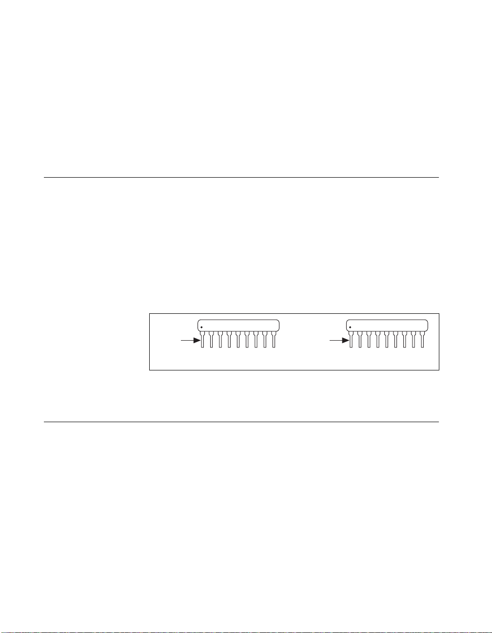
Each resistor network is labeled with descriptive numbers on the left front
side, and pin 1 is located directly beneath the darkened symbol within these
numbers. The 10 Ω resistor network is labeled 100 (10 × 10
resistor network is labeled 106 (10 × 10
these resistors.
0
6
Ω). Figure 1 shows examples of
Ω); the 10 MΩ
10x-1-100
Mfr. code
Pin 1
a. 10 Ω Resistor Network b. 10 MΩ Resistor Network
Figure 1.
Open Thermocouple Detection
The SCXI-1303 circuitry helps you detect an open thermocouple. To detect
whether any thermocouple is open, check whether the corresponding SCXI
module channel is saturated. The SCXI-1303 has pullup and bias resistors
that saturate the channel by applying +5 V at the input of the open channel.
Notice that this will result in saturation to either of the positive or negative
rails.
SCXI-1102/B/C Module
You can replace the 10 Ω bias resistor networks (factory shipping
configuration) in the SCXI-1303 with the 10 MΩ resistor networks
supplied in the kit. With the 10 MΩ resistor networks, it does not matter
SCXI-1303 Installation Guide 2
Pin 1
Resistor Networks
©
National Instruments Corporation
10x-1-106
Mfr. code
Page 3

SCXI-1100 Module
whether your signal is ground-referenced or floating. The channels with
open thermocouples will saturate at all sample rates of the module. To
replace your resistor networks, refer to the Changing Resistor Networks
section.
For the open thermocouple channel to saturate without disturbing th e
measurements on any other channel, use an interchannel delay of 200 µs
at a gain of 100 or higher, which corresponds to a sample rate of 5 kHz.
With the 10 Ω bias resistors installed in the SCXI-1303, you can measure
accurately at the module’s maximum sampling rate, but the open
thermocouple channel may not saturate if the interchannel delay is less
than 200 µs or if the sample rate is more than 5 kHz at a gain of 100 or
higher.
If you want fast open-thermocouple detection and you have a short
thermocouple or if high accuracy is not important, you can replace the
pullup resistors with a lower value resistor network. For example, you
could replace the pullup resistor network with a 1 MΩ, 10-pin bused
configuration resistor network (not supplied) and have a sample rate of
20 kHz (interchannel delay of 50 µs typical). With a 10 Ω bias resistor
network, the current leakage would be 5 µA (5 V/1 MΩ), which may result
in a larger offset error because of thermocouple lead resistance. To replace
your resistor networks, refer to the Changing Resistor Networks section.
Errors Due to Open-Thermocouple Detection Circuitry
Open-thermocouple detection circuitry can cause two types of
measurement errors. These errors are the results of common-mode voltage
at the input of the SCXI module and current leakage into your signal leads.
Common-Mode Voltage at the Input of the
SCXI Module
With 10 MΩ pullup and bias resistors, a common-mode voltage of
2.5 VDC will develop if the thermocouple is floating. At a gain of 100,
the common-mode rejection of the SCXI-1102/B/C module is sufficiently
high that the resulting offset voltage is negligible.
If your application demands extremely high accuracy, you can eliminate
this offset error by calibrating your system. You can also remove the pullup
resistor, giving up the open-thermocouple detection feature in the process
or use the 10 Ω bias resistor networks, which will bring the common-mode
voltage down to nearly 0 VDC.
©
National Instruments Corporation 3 SCXI-1303 Installation Guide
Page 4

Current Leakage
The open thermocouple detection circuitry results in a small current
leakage into the thermocouple. With the 10 MΩ bias and pullup resistor
networks, the current leakage results in a negligible error. With the 10 Ω
bias resistor, the 10 MΩ pullup resistor connected to 5 VDC causes a
current leakage of approximately 0.5 µA (5 V/10 MΩ) to flow into the
unbroken thermocouple. If the thermocouple is very long, a voltage drop
can develop in the thermocouple because of lead resistance. For example,
if you have a 24 AWG J-type thermocouple that is 20 feet long, a voltage
drop of approximately 8.78 µV (0.878 Ω/double ft × 20 double ft × 0.5 µA)
can develop in the thermocouple, which corresponds to an error of 0.18° C.
If your application demands very high accuracy , you may want to eliminate
this error by removing the appropriate pullup resistor network or by
calibrating the system offset.
Temperature Sensor Output and Accuracy
The SCXI-1303 temperature sensor outputs 1.91 to 0.58 V from 0° to 55° C
and has an accuracy of ±0.5° C over the 15° to 35° C range and ±0.9° C
over the 0° to 15° and 35° to 55° C ranges
National Instruments software can convert a thermistor voltage to the
thermistor temperature for the circuit diagram shown later in this guide. In
LabVIEW , you can use the Con vert Thermistor Reading virtual instrument
(VI) in the Data Acquisition»Signal Con di tio ning palette. If you are
using LabWindows/CVI or NI-DAQ, use the
function. The VI takes the output voltage of the temperature sensor, the
reference voltage, and the precision resistance and returns the thermistor
temperature.
1
.
Thermistor_Convert
Alternatively, you can use the following formulas:
T(° C) = T
where T
1
Includes the combined effects of the temperature sensor accuracy and the temperature difference between the temperature
sensor and any screw terminal. The temperature sensor accuracy includes tolerances in all component values, the effects
caused by temperature and loading, and self-heating.
SCXI-1303 Installation Guide 4
is the temperature in Kelvin
K
--------------------------------------------------------------- -=
T
K
++
ab R
[]
– 273.15
K
1
ln
()
T
cR
3
ln
()
T
©
National Instruments Corporation
Page 5

–
a = 1.295361 × 10
b = 2.343159 × 10
c = 1.018703 × 10
3
–
4
–
7
RT = resistance of the thermistor in ohms
V
=
RT5 000
----------------------------------------- -
,
2.5 V
–
TEMPOUT
TEMPOUT
V
TEMPOUT
= output voltage of the temperature sensor
T
()
[T(°C)]9
F
----------------------- 32+=
°
5
where T(° F) and T(° C) are the temperature readings in degrees Fahrenheit
and degrees Celsius, respectively.
Notes V
TEMPOUT
varies from 1.91 V (at 0° C) to 0.58 V (at 55° C). For best resolution,
use the maximum gain for this signal range on the analog input channel.
The SCXI-1102/B/C has a 2 Hz filter on the V
The SCXI-1100 does not have a filter on the V
TEMPOUT
TEMPOUT
signal.
signal. Therefore, use an
average of a large number of samples to obtain the most accurate measurement.
Noisy environments require more samples for greater accuracy.
Configuring the Resistor Networks
Note A package of 10 MΩ resistor networks is included in the SCXI-1303 kit. If you are
using the SCXI-1102/B/C module, you can install these resistor networks as RP1,
RP2, RP3, and RP4. With this recommended configuration, it does not matter
whether the thermocouples are ground-referenced or floating.
The SCXI-1303 terminal block has a pullup resistor connected between
CH+ and +5 V and a bias resistor connected between CH– and chassis
ground. Figure 2 shows how the pullup and bias resistors are connected to
the CH± inputs.
©
National Instruments Corporation 5 SCXI-1303 Installation Guide
Page 6

+5 V
R
pullup
(RP5, RP6, RP7, RP8)
(in sockets)
CH+
Screw Terminals
CH-
CH+
SCXI Module
CH-
R
bias
(RP1, RP2, RP3, RP4)
(in sockets)
Figure 2. Resistor Connections
Table 1 shows the relationship between the channel input signals and the
resistor networks.
Table 1. Channel Input Signals and Resistor Networks
Pullup Resistor
Channel
Network
Bias Resistor Network
0–7 RP5 RP1
8–15 RP6 RP2
16–23 RP7 RP3
24–31 RP8 RP4
T able 2 shows which resistor networks to use for your SCXI module, signal
type, and application.
SCXI-1303 Installation Guide 6
©
National Instruments Corporation
Page 7

Module Bias Resistor
SCXI-1102
/B/C
10 M
Ω
Table 2. Selecting the Appropriate Resistor Networks
Signal
Pullup
Resistor
Ω
10 M
(Floating or
Source
Impedance
Low Both Yes Recommended
Ground-
referenced)
Open
Thermocouple
Detection?
Comments
configuration for the
SCXI-1102/B/C
Ω
10
Ω
10
None None High or low Ground-
SCXI-1100 10 M
low source impedance ≤50
high source impedance >50
Ω
Ω
10
Ω
10
None None High or low Ground-
Ω
Ω
Ω
10 M
None High or low Floating No —
10 M
10 M
None High or low Floating No —
Low Floating Yes Factory-shipping
No —
referenced
Ω
— — — Not recommended
Ω
Low Floating Yes Factory-shipping
No —
referenced
Warning Connecting an external ground-referenced signal with the 10 Ω bias resistor
network in place may cause permanent damage to the resistor network and the
traces on the SCXI-1303 printed circuit board. National Instruments is
for any damage or injuries resulting from improper signal connections.
Signal Connection
When connecting your signals to the SCXI-1303, follow the labeling on the
SCXI-1303 for the appropriate module, as indicated in Figure 4.
configuration
configuration
NOT
liable
To connect the signal to the terminal block, perform the following steps,
referring to Figures 3 and 4 as necessary:
1. Unscrew the top cover screws and remove th e cover.
2. Loosen the strain-relief screws and remove the strain-relief bar.
3. Run the signal wires through the strain-relief opening. You can add
insulation or padding if necessary.
4. Prepare your signal wire by stripping the insulation no more than
7mm.
©
National Instruments Corporation 7 SCXI-1303 Installation Guide
Page 8

5. Connect the wires to the screw terminals by inserting the stripped end
of the wire fully into the terminal. No bare wire should extend past the
screw terminal. Exposed wire increases the risk of shorting and
causing a failure.
6. Tighten the screw terminal to a torque of 5–7 in.-lb.
7. Connect your shield or earth ground to the earth ground solder lug.
8. Reinstall the strain-relief bar and tighten the strain-relief screws.
9. Reinstall the top cover and tighten the top cover screws.
10. Connect the terminal block to the module front connector as explained
in the Installation section later in this guide.
Figure 3 shows the SCXI-1303 terminal block parts locator diagram.
2
1
Back View
1 Strain Relief Bar
2 Strain Relief Screws
4
3 Earth Ground
Solder Lug
6
3
5
Front View
4 Mating Connector
5 Thumbscrew
Figure 3. SCXI-1303 Parts Locator Diagram
6 Top Cover Screws
7 Top Cover
7
SCXI-1303 Installation Guide 8
©
National Instruments Corporation
Page 9

Figure 4 shows the SCXI-1303 signal connections.
1
4
1 Screw Terminals
2 Bias Resistor Networks
Installation
3
3 Pullup Resistor Networks 4 Product Name, Assembly
Figure 4. SCXI-1303 Signal Connections
2
- Pin 1
Number, Revision Letter, and
Serial Number.
To connect the terminal block to the SCXI module front connector, perform
the following steps:
1. Connect the module front connector to its mating connector on the
terminal block.
2. Tighten the top and bottom thumbscrews on the back of the terminal
block to hold it securely in place.
Note Fo r accurate cold-junction compensation, place the SCXI chassis away from an
extreme temperature differential.
©
National Instruments Corporation 9 SCXI-1303 Installation Guide
Page 10

Cleaning the Terminal Block
Clean the terminal block by brushing off light dust with a soft, nonmetallic
brush. Remove other contaminants with deionized water and a stiff
nonmetallic brush. The unit must be completely dry and free from
contaminants before returning to service.
Specifications
Cold-junction sensor
Accuracy
1
........................................0.5° from 15° to 35° C
Repeatability....................................0.2° from 15° to 35° C
Output..............................................1.91 to 0.58 V from 0° to 55° C
Temperature Sensor Circuit Diagram
The circuit diagram in Figure 5 provides optional details about the
SCXI-1303 temperature sensor.
+5 V
0.9° from 0° to 15°
and 35° to 55° C
4.7 kΩ
1%
2.5 V
2
LM 4040
2.5 V
0.1%
1
Includes the combined effects of the temperature sensor accuracy and the temperature difference between the temperature
sensor and any screw terminal. The temperature sensor accuracy includes tolerances in all component values, the effects
caused by temperature and loading, and self-heating.
SCXI-1303 Installation Guide 10
0.1 µF
5 kΩ
0.1%
1
o
5 kΩ
-t
at 25
+
10 µF
o
C
16 V
2
Figure 5.
1
0.1 µF
2
Temperature Sensor Circuit Diagram
BERG 2x2
1
3
W1
2
MTEMP
4
DTEMP (Not Used)
©
National Instruments Corporation
Page 11

 Loading...