

Page 1

TM
SCXI
SCXI-1102/B/C User Manual
SCXI-1102/B/C User Manual
April 2006
371975D-01
Page 2

Support
Worldwide Technical Support and Product Information
ni.com
National Instruments Corporate Headquarters
11500 North Mopac Expressway Austin, Texas 78759-3504 USA Tel: 512 683 0100
Worldwide Offices
Australia 1800 300 800, Austria 43 0 662 45 79 90 0, Belgium 32 0 2 757 00 20, Brazil 55 11 3262 3599,
Canada 800 433 3488, China 86 21 6555 7838, Czech Republic 420 224 235 774, Denmark 45 45 76 26 00,
Finland 385 0 9 725 725 11, France 33 0 1 48 14 24 24, Germany 49 0 89 741 31 30, India 91 80 41190000,
Israel 972 0 3 6393737, Italy 39 02 413091, Japan 81 3 5472 2970, Korea 82 02 3451 3400,
Lebanon 961 0 1 33 28 28, Malaysia 1800 887710, Mexico 01 800 010 0793, Netherlands 31 0 348 433 466,
New Zealand 0800 553 322, Norway 47 0 66 90 76 60, Poland 48 22 3390150, Portugal 351 210 311 210,
Russia 7 095 783 68 51, Singapore 1800 226 5886, Slovenia 386 3 425 4200, South Africa 27 0 11 805 8197,
Spain 34 91 640 0085, Sweden 46 0 8 587 895 00, Switzerland 41 56 200 51 51, Taiwan 886 02 2377 2222,
Thailand 662 278 6777, United Kingdom 44 0 1635 523545
For further support information, refer to the Technical Support Information document. To comment on National
Instruments documentation, refer to the National Instruments Web site at ni.com/info and enter the info code
feedback.
© 1996–2006 National Instruments Corporation. All rights reserved.
Page 3

Important Information
Warranty
The SCXI-1102, SCXI-1102B, and SCXI-1102C modules are warranted against defects in materials and workmanship for a period of one year
from the date of shipment, as evidenced by receipts or other documentation. National Instruments will, at its option, repair or replace equipment
that proves to be defective during the warranty period. This warranty includes parts and labor.
The media on which you receive National Instruments software are warranted not to fail to execute programming instructions, due to defects in
materials and workmanship, for a period of 90 days from date of shipment, as evidenced by receipts or other documentation. National Instruments
will, at its option, repair or replace software media that do not execute programming instruc tions if National Instruments receives notice of such defects
during the warranty period. National Instruments does not warrant that the operation of the software shall be uninterrupted or error free.
A Return Material Authorization (RMA) number must be obtained from the factory and clearly marked on the outside of the package before any
equipment will be accepted for warranty work. National Instruments will pay the shipping costs of returning to the owner parts which are covered by
warranty.
National Instruments believes that the information in this document is accurate. The document has been carefully reviewed for technical accuracy. In
the event that technical or typographical errors exist, National Instruments reserves the right to make changes to subsequent editions of this document
without prior notice to holders of this edition. The reader should consult National Instruments if errors are suspected. In no event shall National
Instruments be liable for any damages arising out of or related to this document or the information contained in it.
E
XCEPT AS SPECIFIED HEREIN, NATIONAL INSTRUMENTS MAKES NO WARRANTIES, EXPRESS OR IMPLIED, AND SPECIFICALLY DISCLAIMS ANY WARRANTY OF
MERCHANTABILITY OR FITNESS FOR A PARTICULAR PURPOSE. CUSTOMER’S RIGHT TO RECOVER DAMAGES CAUSED BY FAULT OR NEGLIGENCE ON THE PART OF NATIONAL
I
NSTRUMENTS SHALL BE LIMITED TO THE AMOUNT THERETOFORE PAID BY THE CUSTOMER. NATIONAL INSTRUMENTS WILL NOT BE LIABLE FOR DAMAGES RESULTING
FROM LOSS OF DATA, PROFITS, USE OF PRODUCTS, OR INCIDENTAL OR CONSEQUENTIAL DAMAGES, EVEN IF ADVISED OF THE POSSIBILITY THEREOF. This limitation of
the liability of National Instruments will apply regardless of the form of action, whether in contract or tort, including negligence. Any action against
National Instruments must be brought within one year after the cause of action accrues. National Instruments shall not be liable for any delay in
performance due to causes beyond its reasonable control. The warranty provided herein does not cover damages, defects, malfunctions, or service
failures caused by owner’s failure to follow the National Instruments installation, operation, or maintenance instructions; owner’s modification of the
product; owner’s abuse, misuse, or negligent acts; and power failure or surges, fire, flood, accident, actions of third parties, or other events outside
reasonable control.
Copyright
Under the copyright laws, this publication may not be reproduced or transmitted in any form, electronic or mechanical, including photocopying,
recording, storing in an information retrieval system, or translating, in whole or in part, without the prior written consent of National
Instruments Corporation.
National Instruments respects the intellectual property of others, and we ask our users to do the same. NI software is protected by copyright and other
intellectual property laws. Where NI software may be used to reproduce software or other materials belonging to others, you may use NI software only
to reproduce materials that you may reproduce in accordance with the terms of any applicable license or other legal restriction.
Trademarks
National Instruments, NI, ni.com, and LabVIEW are trademarks of National Instruments Corporation. Refer to the Terms of Use section
on
ni.com/legal for more information about National Instruments trademarks.
Other product and company names mentioned herein are trademarks or trade names of their respective companies.
Members of the National Instruments Alliance Partner Program are business entities independent from National Instruments and have no agency,
partnership, or joint-venture relationship with National Instruments.
Patents
For patents covering National Instruments products, refer to the appropriate location: Help»Patents in your software, the patents.txt file
on your CD, or ni.com/patents.
WARNING REGARDING USE OF NATIONAL INSTRUMENTS PRODUCTS
(1) NATIONAL INSTRUMENTS PRODUCTS ARE NOT DESIGNED WITH COMPONENTS AND TESTING FOR A LEVEL OF
RELIABILITY SUITABLE FOR USE IN OR IN CONNECTION WITH SURGICAL IMPLANTS OR AS CRITICAL COMPONENTS IN
ANY LIFE SUPPORT SYSTEMS WHOSE FAILURE TO PERFORM CAN REASONABLY BE EXPECTED TO CAUSE SIGNIFICANT
INJURY TO A HUMAN.
(2) IN ANY APPLICATION, INCLUDING THE ABOVE, RELIABILITY OF OPERATION OF THE SOFTWARE PRODUCTS CAN BE
IMPAIRED BY ADVERSE FACTORS, INCLUDING BUT NOT LIMITED TO FLUCTUATIONS IN ELECTRICAL POWER SUPPLY,
COMPUTER HARDWARE MALFUNCTIONS, COMPUTER OPERATING SYSTEM SOFTWARE FITNESS, FITNESS OF COMPILERS
AND DEVELOPMENT SOFTWARE USED TO DEVELOP AN APPLICATION, INSTALLATION ERRORS, SOFTWARE AND HARDWARE
COMPATIBILITY PROBLEMS, MALFUNCTIONS OR FAILURES OF ELECTRONIC MONITORING OR CONTROL DEVICES,
TRANSIENT FAILURES OF ELECTRONIC SYSTEMS (HARDWARE AND/OR SOFTWARE), UNANTICIPATED USES OR MISUSES, OR
ERRORS ON THE PART OF THE USER OR APPLICATIONS DESIGNER (ADVERSE FACTORS SUCH AS THESE ARE HEREAFTER
COLLECTIVELY TERMED “SYSTEM FAILURES”). ANY APPLICATION WHERE A SYSTEM FAILURE WOULD CREATE A RISK OF
HARM TO PROPERTY OR PERSONS (INCLUDING THE RISK OF BODILY INJURY AND DEATH) SHOULD NOT BE RELIANT SOLELY
UPON ONE FORM OF ELECTRONIC SYSTEM DUE TO THE RISK OF SYSTEM FAILURE. TO AVOID DAMAGE, INJURY, OR DEATH,
THE USER OR APPLICATION DESIGNER MUST TAKE REASONABLY PRUDENT STEPS TO PROTECT AGAINST SYSTEM FAILURES,
INCLUDING BUT NOT LIMITED TO BACK-UP OR SHUT DOWN MECHANISMS. BECAUSE EACH END-USER SYSTEM IS
CUSTOMIZED AND DIFFERS FROM NATIONAL INSTRUMENTS' TESTING PLATFORMS AND BECAUSE A USER OR APPLICATION
DESIGNER MAY USE NATIONAL INSTRUMENTS PRODUCTS IN COMBINATION WITH OTHER PRODUCTS IN A MANNER NOT
EVALUATED OR CONTEMPLATED BY NATIONAL INSTRUMENTS, THE USER OR APPLICATION DESIGNER IS ULTIMATELY
RESPONSIBLE FOR VERIFYING AND VALIDATING THE SUITABILITY OF NATIONAL INSTRUMENTS PRODUCTS WHENEVER
NATIONAL INSTRUMENTS PRODUCTS ARE INCORPORATED IN A SYSTEM OR APPLICATION, INCLUDING, WITHOUT
LIMITATION, THE APPROPRIATE DESIGN, PROCESS AND SAFETY LEVEL OF SUCH SYSTEM OR APPLICATION.
Page 4
Conventions
The following conventions are used in this manual:
<> Angle brackets that contain numbers separated by an ellipsis represent
a range of values associated with a bit or signal name—for example,
AO <3..0> .
» The » symbol leads you through nested menu items and dialog box options
to a final action. The sequence File»Page Setup»Options directs you to
pull down the File menu, select the Page Setup item, and select Options
from the last dialog box.
This icon denotes a note, which alerts you to important information.
This icon denotes a caution, which advises you of precautions to take to
avoid injury, data loss, or a system crash. When this icon is marked on the
product, refer to the Read Me First: Safety and Radio-Frequency
Interference document, shipped with the product, for precautions to take.
When symbol is marked on a product it denotes a warning advising you to
take precautions to avoid electrical shock.
When symbol is marked on a product it denotes a component that may be
hot. Touching this component may result in bodily injury.
bold Bold text denotes items that you must select or click in the software, such
as menu items and dialog box options. Bold text also denotes parameter
names.
italic Italic text denotes variables, emphasis, a cross-reference, or an introduction
to a key concept. Italic text also denotes text that is a placeholder for a word
or value that you must supply.
monospace Text in this font denotes text or characters that you should enter from the
keyboard, sections of code, programming examples, and syntax examples.
This font is also used for the proper names of disk drives, paths, directories,
programs, subprograms, subroutines, device names, functions, operations,
variables, filenames, and extensions.
monospace bold Bold text in this font denotes the messages and responses that the computer
automatically prints to the screen. This font also emphasizes lines of code
that are different from the other examples.
Page 5

Contents
Chapter 1
About the SCXI-1102/B/C
What You Need to Get Started ......................................................................................1-2
National Instruments Documentation ............................................................................1-3
Installing Application Software, NI-DAQ, and the DAQ Device .................................1-4
Installing the SCXI-1102/B/C Module into the SCXI Chassis .......................1-4
Connecting the SCXI-1102/B/C in an SCXI Chassis
to an E/M Series DAQ Device for Multiplexed Scanning ...........................1-5
Connecting the SCXI-1102/B/C in a PXI/SCXI Combination Chassis
to an E/M Series DAQ Device for Multiplexed Scanning ...........................1-5
Verifying the SCXI-1102/B/C Installation in Software ................................................1-5
Installing SCXI Using NI-DAQmx in Software .............................................1-5
Manually Adding Modules in NI-DAQmx .....................................................1-5
Installing SCXI Using Traditional NI-DAQ (Legacy) in Software ................1-5
Manually Adding Modules in Traditional NI-DAQ (Legacy) ........................1-6
Verifying and Self-Testing the Installation .....................................................1-6
Troubleshooting the Self-Test Verification ...................................................................1-6
Troubleshooting in NI-DAQmx ......................................................................1-6
Troubleshooting in Traditional NI-DAQ (Legacy) .........................................1-8
Chapter 2
Connecting the Signals
Front Connector .............................................................................................................2-1
Front Connector Signal Descriptions ..............................................................2-3
Analog Input Signal Connections .....................................................2-3
Cold-Junction Sensor Connection ...................................................................2-6
Rear Signal Connector ...................................................................................................2-6
Rear Signal Connector Descriptions ...............................................................2-8
Connecting Thermocouples ..............................................................2-9
Connecting RTDs..............................................................................2-9
Connecting a Current-Loop Receiver ...............................................2-9
Chapter 3
Configuring and Testing
SCXI-1102/B/C Software-Configurable Settings ..........................................................3-1
Common Software-Configurable Settings ......................................................3-1
Gain/Input Range ..............................................................................3-1
CJC Source/Value .............................................................................3-1
© National Instruments Corporation vii SCXI-1102/B/C User Manual
Page 6

Contents
Configurable Settings in MAX...................................................................................... 3-2
NI-DAQmx ..................................................................................................... 3-2
Traditional NI-DAQ (Legacy) ........................................................................ 3-4
Verifying the Signal ...................................................................................................... 3-5
Verifying the Signal in NI-DAQmx Using a Task or Global Channel........... 3-6
Verifying the Signal in Traditional NI-DAQ (Legacy) .................................. 3-6
Chapter 4
Theory of Operation
Rear Signal Connector, SCXIbus Connector, and SCXIbus Interface.......................... 4-2
Digital Control Circuitry ............................................................................................... 4-2
Analog Circuitry............................................................................................................ 4-2
Analog Input Channels.................................................................................... 4-2
Theory of Multiplexed Operation.................................................................................. 4-3
Creating a Global Channel or Task .................................................. 3-3
Configuring Module Property Pages in
Traditional NI-DAQ (Legacy).......................................................3-4
Creating a Virtual Channel ...............................................................3-5
Verifying the Signal Using Virtual Channel .................................... 3-6
Verifying the Signal Using Channel Strings .................................... 3-7
Chapter 5
Using the SCXI-1102/B/C
Developing Your Application in NI-DAQmx............................................................... 5-1
Typical Program Flowchart ............................................................................ 5-1
General Discussion of Typical Flowchart....................................................... 5-3
Creating a Task Using DAQ Assistant or Programmatically ........... 5-3
Adjusting Timing and Triggering..................................................... 5-3
Configuring Channel Properties ....................................................... 5-4
Acquiring, Analyzing, and Presenting.............................................. 5-7
Completing the Application.............................................................. 5-7
Developing an Application Using LabVIEW ................................................. 5-7
Using a NI-DAQmx Channel Property Node in LabVIEW ............. 5-9
Specifying Channel Strings in NI-DAQmx ....................................................5-10
Text Based ADEs ............................................................................. 5-11
Programmable NI-DAQmx Properties ............................................. 5-13
Developing Your Application in Traditional NI-DAQ (Legacy).................................. 5-13
Other Application Documentation and Material ........................................................... 5-14
Using Software for Multiplexed Scanning...................................................... 5-15
LabVIEW and the SCXI Channel String.......................................... 5-15
LabVIEW and the Virtual Channel String ....................................... 5-15
SCXI-1102/B/C User Manual viii ni.com
Page 7

Contents
Performing a Multiplexed Scan.......................................................................5-16
C and Low-Level DAQ Functions .................................................... 5-16
Traditional NI-DAQ (Legacy) CVI Examples ................................................5-17
Traditional NI-DAQ (Legacy) Measurement Studio Examples......................5-17
Calibration .....................................................................................................................5-18
Appendix A
Specifications
Appendix B
Using SCXI Channel Strings with Traditional NI-DAQ (Legacy) 7.0 or
Later
Appendix C
Removing the SCXI-1102/B/C
Appendix D
Common Questions
Appendix E
Current-Loop Receivers
Glossary
Index
© National Instruments Corporation ix SCXI-1102/B/C User Manual
Page 8

Contents
Figures
Tables
Figure 2-1. Ground-Referenced Signal Connection ................................................2-5
Figure 2-2. Floating Signal Connection Referenced to Chassis Ground ................. 2-6
Figure 4-1. SCXI-1102/B/C Module Block Diagram.............................................. 4-1
Figure 5-1. Typical Program Flowchart for Voltage Measurement Channels ........ 5-2
Figure 5-2. Typical SCXI-1102/B/C Program Flow
with Traditional NI-DAQ (Legacy) ...................................................... 5-14
Figure A-1. SCXI-1102/B/C Dimensions ................................................................ A-4
Figure C-1. Removing the SCXI-1102/B/C ............................................................. C-2
Figure E-1. Bent and Trimmed Resistor .................................................................. E-2
Table 2-1. SCXI-1102/B/C Front Signal Pin Assignments ................................... 2-2
Table 2-2. Front Connector Signals ....................................................................... 2-3
Table 2-3. Rear Signal Pin Assignments................................................................ 2-7
Table 2-4. SCXI-1102/B/C Communication Signals ............................................ 2-8
Table 5-1. NI-DAQmx Voltage Measurement Properties ..................................... 5-4
Table 5-2. NI-DAQmx Thermocouple Measurement Properties .......................... 5-5
Table 5-3. NI-DAQmx RTD Measurement Properties ......................................... 5-5
Table 5-4. NI-DAQmx Thermistor Measurement Properties ............................... 5-6
Table 5-5. NI-DAQmx Current Measurement Properties ..................................... 5-6
Table 5-6. Programming a Task in LabVIEW ...................................................... 5-8
Table 5-7. NI-DAQ Functions Used to Configure SCXI-1102/B/C ...................... 5-17
Table D-1. Digital Signals on the SCXI-1102/B/C ................................................ D-2
SCXI-1102/B/C User Manual x ni.com
Page 9

About the SCXI-1102/B/C
This chapter introduces the SCXI-1102/B/C module, and explains how to
install and remove the software and hardware.
The SCXI-1102/B/C modules are for signal conditioning of
thermocouples, low-bandwidth volt and millivolt sources, 4 to 20 mA
current sources, and 0 to 20 mA process-current sources. When used with
the SCXI-1581 precision current source module, you can use the
SCXI-1102/B/C to measure RTDs and thermistors. The SCXI-1102/B/C
has 32 differential analog input channels and one cold-junction sensor
channel. Each channel also has an amplifier with a selectable gain of 1 or
100. You can multiplex the SCXI-1102/B/C inputs to a single output, which
drives a single DAQ device channel.
On each channel the modules have the following:
• SCXI-1102—a two-pole lowpass filter with a 2 Hz cutoff frequency to
reject 60 Hz noise.
• SCXI-1102B—a three-pole lowpass filter with a 200 Hz cutoff
frequency.
• SCXI-1102C—a three-pole lowpass filter with a 10 kHz cutoff
frequency.
1
You can multiplex several SCXI-1102/B/C modules and other SCXI
modules into a single channel on the DAQ device, greatly increasing the
number of analog input signals that you can digitize.
Detailed specifications of the SCXI-1102/B/C modules are listed in
Appendix A, Specifications.
© National Instruments Corporation 1-1 SCXI-1102/B/C User Manual
Page 10

Chapter 1 About the SCXI-1102/B/C
What You Need to Get Started
To set up and use the SCXI-1102/B/C module, you need the following:
❑ Hardware
– At least one of the following modules:
• SCXI-1102
• SCXI-1102B
• SCXI-1102C
– At least one of the following terminal blocks:
• SCXI-1300
• SCXI-1303
• SCXI-1308
• SCXI-1310
• TC-2095
• TBX-1303
•TBX-96
– An SCXI chassis or PXI/SCXI combination chassis
– One of the following:
• E/M Series DAQ device
• SCXI-1600
– A computer if using an SCXI chassis
– Cabling, cable adapter, and sensors as required for your
application
❑ Software
–NI-DAQ
– One of the following software packages:
•LabVIEW
• Measurement Studio
™
• LabWindows
SCXI-1102/B/C User Manual 1-2 ni.com
/CVI
™
Page 11

❑ Documentation
– Read Me First: Safety and Radio-Frequency Interference
– DAQ Getting Started Guide
– SCXI Quick Start Guide
– SCXI-1102/B/C User Manual
– Terminal block installation guide for your application
– Documentation for your software
National Instruments Documentation
The SCXI-1102/B/C User Manual is one piece of the documentation set for
data acquisition (DAQ) systems. You could have any of several types of
manuals depending on the hardware and software in the system. Use the
manuals you have as follows:
• SCXI chassis or PXI/SCXI combination chassis manual—Read this
manual for maintenance information on the chassis and for installation
instructions.
• The DAQ Getting Started Guide—This document has information on
installing NI-DAQ and the E/M Series DAQ device. Install these
before you install the SCXI module.
• The SCXI Quick Start Guide—This document contains a quick
overview for setting up an SCXI chassis, installing SCXI modules and
terminal blocks, and attaching sensors. It also describes setting up the
SCXI system in MAX.
• The SCXI hardware user manuals—Read these manuals next
for detailed information about signal connections and module
configuration. They also explain, in greater detail, how the module
works and contain application hints.
• Accessory installation guides or manuals—Read the terminal block
and cable assembly installation guides. They explain how to physically
connect the relevant pieces of the system. Consult these guides when
you are making the connections.
• The E/M Series DAQ device documentation—This documentation has
detailed information about the E/M Series DAQ device that plugs into
or is connected to the computer. Use this documentation for hardware
installation and configuration instructions, specification information
about the E/M Series DAQ device, and application hints.
Chapter 1 About the SCXI-1102/B/C
© National Instruments Corporation 1-3 SCXI-1102/B/C User Manual
Page 12

Chapter 1 About the SCXI-1102/B/C
• Software documentation—You may have both application software
• One or more of the following help files for software information:
and NI-DAQ software documentation. National Instruments (NI)
application software includes LabVIEW, LabWindows/CVI, and
Measurement Studio. After you set up the hardware system, use either
your application software documentation or the NI-DAQ
documentation to help you write your application. If you have a large,
complex system, it is worthwhile to look through the software
documentation before you configure the hardware.
– Start»Programs»National Instruments»NI-DAQ»
NI-DAQmx Help
– Start»Programs»National Instruments»NI-DAQ»
Traditional NI-DAQ User Manual
– Start»Programs»National Instruments»NI-DAQ»
Traditional NI-DAQ Function Reference Help
You can download NI documents from
the latest version of NI-DAQ, click Download Software at
ni.com/manuals. To download
ni.com.
Installing Application Software, NI-DAQ, and the DAQ Device
Refer to the DAQ Getting Started Guide packaged with the NI-DAQ
software to install your application software, NI-DAQ driver software, and
the E/M Series DAQ device to which you will connect the SCXI-1102/B/C.
NI-DAQ 7.0 or later is required to configure and program the
SCXI-1102/B/C module. If you do not have NI-DAQ 7.0 or later, you can
either contact a NI sales representative to request it on a CD or download
the latest NI-DAQ version from
Note Refer to the Read Me First: Safety and Radio-Frequency Interference document
before removing equipment covers or connecting or disconnecting any signal wires.
Installing the SCXI-1102/B/C Module into the SCXI Chassis
Refer to the SCXI Quick Start Guide to install the SCXI-1102/B/C module.
ni.com.
SCXI-1102/B/C User Manual 1-4 ni.com
Page 13

Chapter 1 About the SCXI-1102/B/C
Connecting the SCXI-1102/B/C in an SCXI Chassis to an E/M Series DAQ Device for Multiplexed Scanning
Refer to the SCXI Quick Start Guide to install the cable adapter and connect
the SCXI modules to the E/M Series DAQ device.
If you have already installed the appropriate software, refer to Chapter 3,
Configuring and Testing, to configure the SCXI-1102/B/C module(s).
Connecting the SCXI-1102/B/C in a PXI/SCXI Combination Chassis to an E/M Series DAQ Device for Multiplexed Scanning
Refer to the SCXI Quick Start Guide to connect the SCXI modules to the
E/M Series DAQ device.
If you have already installed the appropriate software, refer to Chapter 3,
Configuring and Testing, to configure the SCXI-1102/B/C module(s).
Verifying the SCXI-1102/B/C Installation in Software
Refer to the SCXI Quick Start Guide for information on verifying the SCXI
installation.
Installing SCXI Using NI-DAQmx in Software
Refer to the SCXI Quick Start Guide for information on installing modules
using NI-DAQmx in software.
Manually Adding Modules in NI-DAQmx
If you did not auto-detect the SCXI modules, you must manually add each
of the modules. Refer to the SCXI Quick Start Guide to manually add
modules.
Note NI recommends auto-detecting modules for the first time configuration of the
chassis.
Installing SCXI Using Traditional NI-DAQ (Legacy) in Software
Refer to the SCXI Quick Start Guide for information on installing modules
using Traditional NI-DAQ (Legacy) in software.
© National Instruments Corporation 1-5 SCXI-1102/B/C User Manual
Page 14

Chapter 1 About the SCXI-1102/B/C
Manually Adding Modules in Traditional NI-DAQ (Legacy)
If you did not auto-detect the SCXI modules, you must manually add each
of the modules. Refer to the SCXI Quick Start Guide to manually add
modules.
Note NI recommends auto-detecting modules for the first time configuration of the
chassis.
Verifying and Self-Testing the Installation
The verification procedure for the SCXI chassis is the same for both
NI-DAQmx and Traditional NI-DAQ (Legacy). To test the successful
installation for the SCXI chassis, refer to the SCXI Quick Start Guide.
Verify that the chassis is powered on and correctly connected to an
E/M Series DAQ device.
After verifying and self-testing the installation, the SCXI system should
operate properly with your ADE software. If the test did not complete
successfully, refer to Chapter 3, Configuring and Testing, for
troubleshooting steps.
Troubleshooting the Self-Test Verification
If the self-test verification did not verify the chassis configuration,
complete the steps in this section to troubleshoot the SCXI configuration.
Troubleshooting in NI-DAQmx
• If you get a Verify SCXI Chassis message box showing the SCXI
chassis model number, Chassis ID: x, and one or more messages
stating Slot Number: x Configuration has module: SCXI-XXXX
or 1102/B/C, hardware in chassis is: Empty, take the following
troubleshooting actions:
– Make sure the SCXI chassis is powered on.
– Make sure all SCXI modules are properly installed in the chassis.
Refer to the SCXI Quick Start Guide for proper installation
instructions.
– Make sure the cable between the SCXI chassis and E/M Series
DAQ device is properly connected.
– Inspect the cable connectors for bent pins.
SCXI-1102/B/C User Manual 1-6 ni.com
Page 15

Chapter 1 About the SCXI-1102/B/C
– Make sure you are using the correct NI cable assembly.
– Test the E/M Series DAQ device to verify it is working properly.
Refer to the E/M Series DAQ device help file for more
information.
• If you get a Verify SCXI Chassis message box showing the SCXI
chassis model number, Chassis ID: x, and the message Slot
Number: x Configuration has module: SCXI-XXXX or 1102/B/C,
hardware in chassis is: SCXI-YYYY, 1102/B/C, or Empty, complete
the following troubleshooting steps to correct the error.
1. Expand the list of NI-DAQmx devices by clicking the + next to
NI-DAQmx Devices.
2. Right-click the SCXI chassis and click Properties to load the
chassis configurator.
3. Under the Modules tab, ensure that the cabled module is listed in
the correct slot.
4. If the cabled module is not listed in the correct slot, complete the
following troubleshooting steps:
a. If the cabled module is not listed in the correct slot and the
slot is empty, click the drop-down listbox next to the correct
slot and select the cabled module. Configure the cabled
module following the steps listed in the SCXI Quick Start
Guide. Click OK.
b. If another module appears where the cabled module should
be, click the drop-down listbox next to the correct slot and
select the cabled module. A message box appears asking you
to confirm the module replacement. Click OK. Configure the
cabled module following the steps listed in the SCXI Quick
Start Guide. Click OK.
• If you have more than one kind of SCXI module in the SCXI chassis,
ensure that you have the highest priority SCXI module cabled to the
E/M Series DAQ device. Refer to the SCXI Quick Start Guide to find
out which SCXI module in the chassis should be cabled to the
E/M Series DAQ device.
• After checking the preceding items, return to the Troubleshooting the
Self-Test Verification section and retest the SCXI chassis.
If these measures do not successfully configure the SCXI system, contact
NI. Refer to the Technical Support Information document for contact
information.
© National Instruments Corporation 1-7 SCXI-1102/B/C User Manual
Page 16

Chapter 1 About the SCXI-1102/B/C
Troubleshooting in Traditional NI-DAQ (Legacy)
• If you get the message Unable to test chassis at this time,
you have not designated at least one module as connected to a E Series
DAQ device. Refer to the Traditional NI-DAQ (Legacy) section of
Chapter 3, Configuring and Testing,
the cabled module in the system from Connected to: None to
Connected to: Device x.
• If you get the message
codes and the message
take the following troubleshooting actions:
– Make sure the SCXI chassis is powered on.
– Make sure the cable between the SCXI chassis and E Series DAQ
device is properly connected.
– Inspect the cable connectors for bent pins.
– Make sure you are using the correct NI cable assembly.
– Test the E Series DAQ device to verify it is working properly.
Refer to the E Series DAQ device help file for more information.
• If you get the message
and the message
to the Traditional NI-DAQ (Legacy) section of Chapter 3, Configuring
and Testing, and make sure the correct module is in the specified slot.
Delete the incorrect module as described in Appendix C, Removing the
SCXI-1102/B/C, and add the correct module as described in the
Traditional NI-DAQ (Legacy) section of Chapter 3, Configuring and
Testing.
• If you get the message
and the message
is installed in the specified slot. If not, install the module by following
the instructions in the SCXI Quick Start Guide. If the module is
installed in the correct slot, power off the chassis, remove the module
as specified in Appendix C, Removing the SCXI-1102/B/C, and verify
that no connector pins are bent on the rear signal connector. Reinstall
the module as described in the SCXI Quick Start Guide, ensuring
the module is fully inserted and properly aligned in the slot.
• After checking the preceding items, return to the Troubleshooting the
Self-Test Verification section and retest the SCXI chassis.
Failed to find followed by the module
Unable to communicate with chassis,
Failed to find, followed by module codes
Instead found: module with ID 0Xxx, refer
Failed to find, followed by a module code
Slot x is empty, make sure the configured module
and change the configuration of
If these measures do not successfully configure the SCXI system, contact
NI. Refer to the Technical Support Information document for contact
information.
SCXI-1102/B/C User Manual 1-8 ni.com
Page 17

Connecting the Signals
This chapter describes the input and output signal connections to the
SCXI-1102/B/C module with the module front connector and rear signal
connector. This chapter also includes connection instructions for the
signals on the SCXI-1102/B/C module connectors.
Refer to the installation guide of the terminal block for detailed information
regarding connecting the signals. If you are using a custom cable or
connector block, refer to the Front Connector section.
Front Connector
Table 2-1 shows the pin assignments for the SCXI-1102/B/C module front
connector.
2
© National Instruments Corporation 2-1 SCXI-1102/B/C User Manual
Page 18
Chapter 2 Connecting the Signals
Table 2-1. SCXI-1102/B/C Front Signal Pin Assignments
Front Connector Diagram Pin Number Column A Column B Column C
32 CH GND AI 0 – AI 0 +
Column
ABC
32
31
30
29
28
27
26
25
24
23
22
21
20
19
18
17
16
15
14
13
12
11
10
9
8
7
6
5
4
3
2
1
NC—No Connection
31 NC AI 1 – AI 1 +
30 NC AI 2 – AI 2 +
29 NC AI 3 – AI 3 +
28 NC AI 4 – AI 4 +
27 NC AI 5 – AI 5 +
26 NC AI 6 – AI 6 +
25 NC AI 7 – AI 7 +
24 CH GND AI 8 – AI 8 +
23 NC AI 9 – AI 9 +
22 NC AI 10 – AI 10 +
21 NC AI 11 – AI 11 +
20 NC AI 12– AI 12 +
19 NC AI 13 – AI 13 +
18 NC AI 14 – AI 14 +
17 NC AI 15 – AI 15 +
16 CH GND AI 16 – AI 16 +
15 NC AI 17 – AI 17 +
14 NC AI 18 – AI 18 +
13 NC AI 19 – AI 19 +
12 NC AI 20 – AI 20 +
11 NC AI 21 – AI 21 +
10 NC AI 22 – AI 22 +
9 NC AI 23 – AI 23 +
8 NC AI 24 – AI 24 +
7 NC AI 25 – AI 25 +
6 NC AI 26 – AI 26 +
5 CH GND AI 27 – AI 27 +
4 CJ SENSOR AI 28 – AI 28 +
3 CJ SENSOR AI 29 – AI 29 +
2 CH GND AI 30 – AI 30 +
1 +5 V AI 31 – AI 31 +
SCXI-1102/B/C User Manual 2-2 ni.com
Page 19

Chapter 2 Connecting the Signals
Front Connector Signal Descriptions
Table 2-2. Front Connector Signals
Pin Signal Name Description
A1 +5 V +5 VDC Source—Used to power the
temperature sensor on the terminal block.
0.2 mA of source not protected.
A2, A5, A16, A24,
A32
A3, A4 CJ SENSOR Cold-junction Temperature Sensor
B1–B32 AI 31 – through AI 0 – Negative Input Channels—Negative side of
C1–C32 AI 31 + through AI 0 + Positive Input Channels 31 through
Note: All other pins are not connected.
CH GND Chassis Ground—Tied to the SCXI chassis.
Input—Connects to the temperature sensor
of the terminal block.
differential input channels.
0—Positive side of differential input
channels.
Analog Input Signal Connections
The signal terminals for the negative input channel are located in column B
of the connector. The signal terminal for each corresponding positive input
channel is located in column C of the connector. Each input goes to a
separate filter and amplifier that is multiplexed to the module output buffer.
If the terminal block has a temperature sensor, the sensor output—
connected to pins A3 and A4 (CJ SENSOR)—is also filtered and
multiplexed to the module output buffer.
The differential input signal range of an SCXI-1102/B/C module input
channel is ±10 V when using a gain of 1 or ±0.1 V when using a gain of
100. This differential input range is the maximum measurable voltage
difference between the positive and negative channel inputs. The
common-mode input signal range of an SCXI-1102/B/C module input
channel is ±10 V. This common-mode input range for either positive or
negative channel input is the maximum input voltage that results in a valid
measurement. Each channel includes input protection circuitry to withstand
the accidental application of voltages up to ±42 VAC peak or 60 VDC.
© National Instruments Corporation 2-3 SCXI-1102/B/C User Manual
Page 20

Chapter 2 Connecting the Signals
Cautions Exceeding the input damage level (±42 VAC peak or 60 VDC between input
channels and chassis ground) can damage the SCXI-1102/B/C module, the SCXIbus, and
the DAQ device. NI is not liable for any injuries resulting from such signal connections.
Applying a voltage greater than ±42 VAC peak or 60 VDC to the SCXI-1102/B/C is an
electrical shock hazard. NI is not liable for any damages or injuries resulting from such
voltage application.
Note Exceeding the differential or common-mode input channel ranges results in a
distorted signal measurement, and can also increase the settling time requirement of the
connected E/M Series DAQ device.
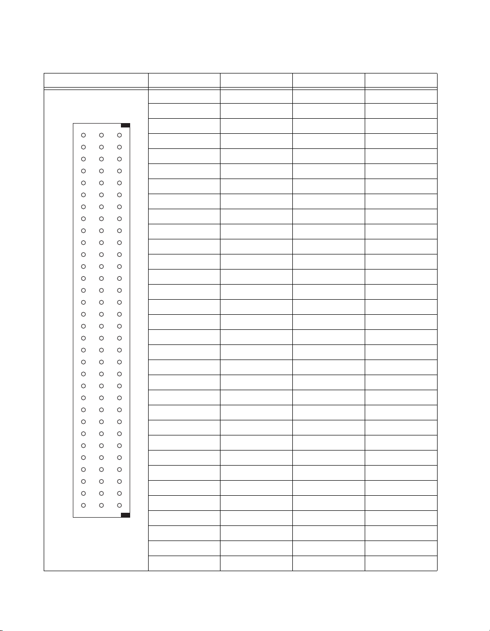
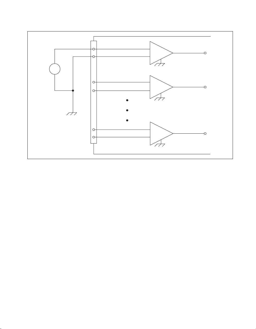
Ground-Referencing the Signals
The input signals can be either ground-referenced, as shown in Figure 2-1,
or floating, as shown in Figure 2-2. Before you connect the thermocouple
or any other signal, determine whether it is floating or ground-referenced.
If it is a floating signal, you must ground-reference the signal in one of two
ways. You can connect the negative channel input to chassis ground
through a bias resistor as shown in Figure 2-2 or you can use the bias
resistors that are included with some terminal blocks such as the
SCXI-1303. The SCXI-1303 also has a resistor pack for pulling up the
positive inputs for open-thermocouple detection. Consult the installation
guide of your terminal block for details.
Do not ground signals that are already ground-referenced; doing so results
in a ground loop, which adversely affects the measurement accuracy.
Directly grounding floating signals to the chassis ground without using a
bias resistor is not recommended as this can result in noisy readings.
SCXI-1102/B/C User Manual 2-4 ni.com
Page 21
Chapter 2 Connecting the Signals
CH 0+
CH 0–
+
–
+
V
s
–
CH 1+
CH 1–
Connector
Front Signal
CH 31+
CH 31–
+
–
+
–
SCXI - 1102/B/C
Figure 2-1. Ground-Referenced Signal Connection
© National Instruments Corporation 2-5 SCXI-1102/B/C User Manual
Page 22
Chapter 2 Connecting the Signals
CH 0+
CH 0–
Floating
Signal
Make This
Connection
to Ground
Reference
the Signal
+
V
s
–
Referenced to
Chassis Ground
CH 1+
CH 1–
R
bias
Connector
Front Signal
CH 31+
CH 31–
CH GND
Figure 2-2. Floating Signal Connection Referenced to Chassis Ground
Cold-Junction Sensor Connection
Pins A3 and A4 (CJ SENSOR) connect the temperature sensor located on
the SCXI-1300 or SCXI-1303 terminal blocks to the SCXI-1102/B/C
module. The CJ SENSOR signal is measured relative to CH GND. Pins A3
and A4 are connected within the SCXI-1102/B/C module so the position of
the MTEMP/DTEMP jumper on the SCXI-1300 or SCXI-1303 does not
matter. The input is overvoltage-protected to 15 VDC with power on
and off.
+
–
+
–
+
–
SCXI - 1102/B/C
Caution Exceeding the overvoltage protection on the CJ SENSOR input can damage the
SCXI-1102/B/C module, the SCXIbus, and the DAQ device. NI is not liable for any
damages or injuries resulting from such signal connections.
Rear Signal Connector
Table 2-3 shows the SCXI-1102/B/C module rear signal connector pin
assignments.
SCXI-1102/B/C User Manual 2-6 ni.com
Page 23
Rear Connector
Diagram
2
1
4
3
6
5
8
7
10
9
12
11
14
13
16
15
18
17
20
19
22
21
24
23
26
25
28
27
30
29
32
31
34
33
36
35
38
37
40
39
42
41
44
43
46
45
48
47
50
49
Chapter 2 Connecting the Signals
Table 2-3. Rear Signal Pin Assignments
Signal Name Pin Number Pin Number Signal Name
AI GND 1 2 AI GND
CH 0 + 3 4 CH 0 –
NC 5 6 NC
NC 7 8 NC
NC 9 10 NC
NC 11 12 NC
NC 13 14 NC
NC 15 16 NC
NC 17 18 NC
OUT REF 19 20 NC
NC 21 22 NC
NC 23 24 D GND
SER DAT IN 25 26 SER DAT OUT
DAQ D*/A 27 28 NC
SLOT 0 SEL* 29 30 NC
D GND 31 32 NC
NC 33 34 NC
NC 35 36 AI HOLD COMP, AI HOLD
SER CLK 37 38 NC
NC 39 40 NC
NC 41 42 NC
RSVD 43 44 NC
NC—No
Connection
© National Instruments Corporation 2-7 SCXI-1102/B/C User Manual
NC 45 46 RSVD
NC 47 48 NC
NC 49 50 NC
Page 24

Chapter 2 Connecting the Signals
Rear Signal Connector Descriptions
The rear signal connector on the cabled module is the interface between
the DAQ device and all modules in the SCXI chassis. CH 0 is used to
differentially multiplex all 32 channels, the CJ sensor, and analog signals
from the modules to the connected DAQ device.
The communication signals between the DAQ device and the SCXI
system are listed in Table 2-4. If the DAQ device is connected to the
SCXI-1102/B/C, these digital lines are unavailable for general-purpose
digital I/O.
Table 2-4. SCXI-1102/B/C Communication Signals
NI-DAQmx
SCXI
Pin
24, 33 DIG GND D GND DGND — Digital ground—these
25 SER DAT IN P0.0 DIO0 Input Serial data in—this
26 SER DAT OUT P0.4 DIO4 Output Serial data out—this
27 DAQ D*/A P0.1 DIO1 Input Board data/address
Signal Name
Device Signal
Name
Traditional NI-DAQ
(Legacy) Device
Signal Name
Direction Description
pins supply the
reference for
E/M Series DAQ device
digital signals and are
connected to the
module digital ground.
signal taps into the
SCXIbus MOSI line to
send serial input data to
a module or Slot 0.
signal taps into the
SCXIbus MISO line to
accept serial output data
from a module.
line—this signal taps
into the SCXIbus D*/A
line to indicate to the
module whether the
incoming serial stream
is data or address
information.
SCXI-1102/B/C User Manual 2-8 ni.com
Page 25

Chapter 2 Connecting the Signals
Table 2-4. SCXI-1102/B/C Communication Signals (Continued)
NI-DAQmx
SCXI
Pin
29 SLOT0SEL* P0.2 DIO2 Input Slot 0 select—this
36 SCANCLK AI HOLD COMP,
37 SER CLK EXTSTROBE* EXTSTROBE* Input Serial clock—this
43, 46 RSVD RSVD RSVD Input Reserved.
Note: All other pins are not connected.
Signal Name
Device Signal
Name
AI HOLD
Traditional NI-DAQ
(Legacy) Device
Signal Name
SCANCLK Input Scan clock—a rising
Direction Description
signal taps into the
SCXIbus INTR* line to
indicate whether the
information on MOSI is
being sent to a module
or Slot 0.
edge indicates to the
scanned SCXI module
that the E/M Series
DAQ device has taken a
sample and causes the
module to advance
channels.
signal taps into the
SCXIbus SPICLK line
to clock the data on the
MOSI and MISO lines.
Connecting Thermocouples
Refer to the terminal block installation guide, such as the SCXI-1303, for
information about connecting thermocouples. NI recommends using an
isothermal terminal block, such as the SCXI-1303, for accurate
thermocouple measurements.
Connecting RTDs
Refer to the SCXI-1581 User Manual for information about connecting
RTDs and for additional RTD theory.
Connecting a Current-Loop Receiver
Refer to Appendix E, Current-Loop Receivers, for information about
connecting current loop receivers.
© National Instruments Corporation 2-9 SCXI-1102/B/C User Manual
Page 26

Configuring and Testing
This chapter discusses configuring the SCXI-1102/B/C in MAX for use
with either NI-DAQmx or Traditional NI-DAQ (Legacy), creating and
testing a virtual channel, global channel, and/or task.
SCXI-1102/B/C Software-Configurable Settings
This section describes how to set the gain/input signal range and how to
configure your software for compatible sensor types. It also describes how
to perform configuration of these settings for the SCXI-1102/B/C in
NI-DAQmx and Traditional NI-DAQ (Legacy). For more information on
the relationship between the settings and the measurements and how to
configure settings in your application, refer to Chapter 4, Theory of
Operation.
Common Software-Configurable Settings
This section describes the most frequently used software-configurable
settings for the SCXI-1102/B/C. Refer to Chapter 4, Theory of Operation,
for a complete list of software-configurable settings.
3
Gain/Input Range
Gain/input range is a software-configurable setting that allows you to
choose the appropriate amplification to fully utilize the range of the
E/M Series DAQ device. In most applications NI-DAQ chooses and sets
the gain for you determined by the input range. This feature is described in
Chapter 4, Theory of Operation. Otherwise, you should determine the
appropriate gain using the input signal voltage range and the full-scale
limits of the SCXI-1102/B/C output. You can select a gain of 1 or 100 on a
per channel basis.
CJC Source/Value
When using a terminal block that has a CJ sensor for thermocouple
measurements, you can set the CJC source as internal, which scans the
sensor at the beginning of each measurement and scales the readings
accordingly.
© National Instruments Corporation 3-1 SCXI-1102/B/C User Manual
Page 27

Chapter 3 Configuring and Testing
Configurable Settings in MAX
Note If you are not using an NI ADE, using an NI ADE prior to version 7.0, or are using
an unlicensed copy of an NI ADE, additional dialog boxes from the NI License Manager
appear allowing you to create a task or global channel in unlicensed mode. These messages
continue to appear until you install version 7.0 or later of an NI ADE.
This section describes where users can access each software-configurable
setting for modification in MAX. The location of the settings varies
depending on the version of NI-DAQ you use. Refer to either the
NI-DAQmx section or the Traditional NI-DAQ (Legacy) section. You also
can refer to the DAQ Getting Started Guide and the SCXI Quick Start Guide
for more information on installing and configuring the hardware. You also
can use the DAQ Assistant to graphically configure common measurement
tasks, channels, or scales.
NI-DAQmx
Using NI-DAQmx, you can configure software settings such as sensor type
and gain/input signal range in the following ways:
• Task or global channel in MAX
• Functions in your application
Note All software-configurable settings are not configurable both ways. This section only
discusses settings in MAX. Refer to Chapter 4, Theory of Operation, for information on
using functions in your application and for information on configuring the settings for your
application using Traditional NI-DAQ (Legacy).
You can use the SCXI-1102/B/C module to make the following types of
measurements:
• Voltage input
• Thermocouple
•RTD
• Thermistors
• Current input
SCXI-1102/B/C User Manual 3-2 ni.com
Page 28

Chapter 3 Configuring and Testing
Creating a Global Channel or Task
To create a new voltage, temperature, or current input NI-DAQmx global
task or channel, complete the following steps:
1. Double-click Measurement & Automation on the desktop.
2. Right-click Data Neighborhood and select Create New.
3. Select NI-DAQmx Task or NI-DAQmx Global Channel, and click
Next.
4. Select Analog Input.
5. Select one of the following:
• Voltage
• Temperature
and then select one of the following:
– Iex Thermistor
– RTD
– Thermocouple
– Vex Thermistor
• Current
6. If you are creating a task, you can select a range of channels by holding
down the <Shift> key while selecting the channels. You can select
multiple individual channels by holding down the <Ctrl> key while
selecting channels. If you are creating a channel, you can only select
one channel. Click Next.
7. Name the task or channel and click Finish.
8. Select the channel(s) you want to configure. You can select a range of
channels by holding down the <Shift> key while selecting the
channels. You can select multiple individual channels by holding down
the <Ctrl> key while selecting channels.
Note If you want to add channels of various measurement types to the same task, click
the Add Channels button to select the measurement type for the additional channels.
9. Enter the specific values for your application in the Settings tab.
Context help information for each setting is provided on the right
side of the screen. Configure the input signal range using either
NI-DAQmx Task or NI-DAQmx Global Channel. When you set the
minimum and maximum range of NI-DAQmx Task or NI-DAQmx
Global Channel, the driver selects the best gain for the measurement.
© National Instruments Corporation 3-3 SCXI-1102/B/C User Manual
Page 29

Chapter 3 Configuring and Testing
You also can set it through your application. Refer to Chapter 3,
Configuring and Testing, for more information.
10. If you are creating a task and want to set timing or triggering controls,
enter the values in the Task Timing and Task Triggering tabs.
Traditional NI-DAQ (Legacy)
Using Traditional NI-DAQ (Legacy), you can configure software settings,
such as gain/input signal range in the following three ways:
• module property pages in MAX
• virtual channels properties in MAX
• functions in your ADE
Note All software-configurable settings are not configurable in all three ways. This
section only discusses settings in MAX. Refer to Chapter 4, Theory of Operation, for
information on using functions in your application.
Most of these settings are available in module properties and/or using
virtual channels:
• Gain/input signal range—configure gain using module properties.
When you set the minimum and maximum range of the virtual
channel, the driver selects the best gain. The default gain setting
for Traditional NI-DAQ (Legacy) is 100.
Note Refer to Chapter 4, Theory of Operation, for information on configuring the settings
for your application using Traditional NI-DAQ (Legacy).
Configuring Module Property Pages in Traditional
NI-DAQ (Legacy)
1. Right-click the SCXI-1102/B/C module you want to configure and
select Properties. Click General.
2. If the module you are configuring is connected to an E Series DAQ
device, select that device by using Connected to. If you want the
E Series DAQ device to control the chassis, confirm there is a check in
the This device will control the chassis checkbox. If the module you
are configuring is not connected to an E Series DAQ device, select
None.
SCXI-1102/B/C User Manual 3-4 ni.com
Page 30

Chapter 3 Configuring and Testing
3. Click the Channel tab. Select the appropriate gain for each channel. If
you want to configure all the channels at the same time, select the
Channel drop-down list, scroll to the bottom, and select All Channels.
Refer to the SCXI-1102/B/C Software-Configurable Settings section
for a detailed description of each setting. Click Apply.
4. Click Accessory. Select the accessory you connected to the module.
When configuration is complete, click OK.
The Traditional NI-DAQ (Legacy) chassis and SCXI-1102/B/C should now
be configured properly. If you need to change the module configuration,
right-click the module and repeat steps 1 through 4. Test the system
following the steps in the Troubleshooting the Self-Test Verification
section of Chapter 1, About the SCXI-1102/B/C.
Creating a Virtual Channel
To create a virtual channel, complete the following steps:
1. Right-click Data Neighborhood and select Create New.
2. Select Traditional NI-DAQ Virtual Channel and click Finish.
3. Select Analog Input from the drop-down menu and click Next.
4. Enter the Channel Name and Channel Description, and click Next.
5. Select one of the following measurement types from the drop-down
menu:
• Voltage
• X Thermocouple
• X RTD
• Current
6. Click Next.
7. The next windows ask for information that is dependent upon the
selection made in step 5. Supply the needed information and click
Next as needed.
8. Click Finish.
Verifying the Signal
This section describes how to take measurements using test panels in order
to verify signal, and configuring and installing a system in NI-DAQmx and
Traditional NI-DAQ (Legacy).
© National Instruments Corporation 3-5 SCXI-1102/B/C User Manual
Page 31

Chapter 3 Configuring and Testing
Verifying the Signal in NI-DAQmx Using a Task or Global Channel
You can verify the signals on the SCXI-1102/B/C using NI-DAQmx by
completing the following steps:
1. Click + next to Data Neighborhood.
2. Click + next to NI-DAQmx Tasks.
3. Click the task.
4. Select the channel(s) you want to verify. You can select a block of
channels by holding down the <Shift> key or multiple channels by
holding down the <Ctrl> key. Click OK.
5. Enter the appropriate information on the Settings tab.
6. Click the Test button.
7. Click the Start button.
8. After you have completed verifying the channels, click the Stop
button.
You have now verified the SCXI-1102/B/C configuration and signal
connection.
Note For more information on how to further configure the SCXI-1102/B/C, or how to use
LabVIEW to configure the module and take measurements, refer to Chapter 4, Theory of
Operation.
Verifying the Signal in Traditional NI-DAQ (Legacy)
This section discusses how to verify the signal in Traditional NI-DAQ
(Legacy) using channel strings and virtual channels.
Verifying the Signal Using Virtual Channel
If you have already created a virtual channel, complete the following steps
to verify the signal:
1. Right-click the virtual channel you want to verify and select Test.
2. In Channel Names, select the channel you want to verify.
3. When you have completed verifying the channel, click Close.
SCXI-1102/B/C User Manual 3-6 ni.com
Page 32

Chapter 3 Configuring and Testing
Verifying the Signal Using Channel Strings
Refer to AppendixChapter B, Using SCXI Channel Strings with
Traditional NI-DAQ (Legacy) 7.0 or Later, for information about
formatting channel strings.
Complete the following steps to use channel strings in verifying the signal:
1. Click + next to Devices and Interfaces.
2. Click + next to Traditional NI-DAQ Devices.
3. Right-click the appropriate E Series DAQ device.
4. Click Test Panels.
5. Enter the channel string.
6. Enter the input limits.
7. Select the Data Mode.
8. Select the Y Scale Mode.
Refer to the LabVIEW Measurements Manual for more information and for
proper formatting of channel strings for different uses.
© National Instruments Corporation 3-7 SCXI-1102/B/C User Manual
Page 33

Theory of Operation
This section includes a brief overview and a detailed discussion of the
circuit features of the module.
Refer to Figure 4-1 while reading this section.
4
CH 0 +
CH 0 –
Input Protection
and Lowpass Filter
CH 31+
CH 31–
Front Signal Connector
CJSENSOR
Input Protection
and Lowpass Filter
Input Protection
and Lowpass Filter
+
Inst.
Amp
–
+
Inst.
Amp
–
Gain 0
Gain 31
Lowpass
Filter
Lowpass
Filter
Lowpass
Filter
Buffer
Buffer
Buffer
32-to-1 Mux
Buffer
Mux
Gain
Register
Calibration EEPROM
Switch
Digital
Control
Switch
Switch
Mux
SCXIbus
Interface
CH 0 +
CH 0 –
AO GND
OUT REF
Rear Signal Connector
AB 0 +
AB 0 –
SCXIbus Connector
Figure 4-1. SCXI-1102/B/C Module Block Diagram
The major components of the SCXI-1102/B/C modules are as follows:
• Rear signal connector
• SCXIbus connector
• SCXIbus interface
© National Instruments Corporation 4-1 SCXI-1102/B/C User Manual
Page 34

Chapter 4 Theory of Operation
• Digital control circuitry
• Analog circuitry
The SCXI-1102/B/C modules consist of 32 multiplexed input channels,
each with a software-programmable gain of 1 or 100. Each input channel
has its own lowpass filter. The SCXI-1102/B/C modules also have a digital
section for automatic control of channel scanning, temperature sensor
selection, and gain selection.
Rear Signal Connector, SCXIbus Connector, and SCXIbus Interface
The SCXIbus controls the SCXI-1102/B/C module. The SCXIbus interface
connects the rear signal connector to the SCXIbus, allowing a DAQ device
to control the SCXI-1102/B/C module and the rest of the chassis.
Digital Control Circuitry
The digital control circuitry consists of the Address Handler and registers
that are necessary for identifying the module, starting calibration
information, setting the gain, and selecting the appropriate channel.
Analog Circuitry
The analog circuitry per channel consists of a lowpass filter and an
amplifier with a software selectable gain of 1 or 100. The CJ SENSOR
channel also has a buffered lowpass filter but has no amplifier. The
channels and CJ SENSOR are multiplexed to a single output buffer.
Analog Input Channels
Each of the 32 analog input channels feeds to a separate amplifier with a
programmable gain of 1 or 100. Then the signal passes through a fixed
lowpass filter.
Note Because of the 2 Hz bandwidth of the SCXI-1102 module input channels, after
changing the gains you must wait approximately 3 s for the channels settle in order to get
an accurate measurement. NI-DAQ automatically accounts for this time and determines
when the module output has settled. For the SCXI-1102B and SCXI-1102C modules, this
time is approximately 100 ms and 1 ms, respectively.
SCXI-1102/B/C User Manual 4-2 ni.com
Page 35

The CJ SENSOR input channel is used to read the sensor temperature from
the terminal blocks that have one, such as the SCXI-1300 and SCXI-1303.
The temperature sensor is for cold-junction compensation thermocouple
measurements. The CJ SENSOR channel also passes through a 2 Hz
lowpass filter to reject unwanted noise on the SCXI-1102/B/C. Along with
the other 32 input channels, the CJ SENSOR is multiplexed to the output
buffer, where it can be read by the DAQ device.
Theory of Multiplexed Operation
The SCXI-1102/B/C operates in multiplexed mode. which means that all
input channels of the SCXI module are multiplexed into a single analog
input channel of the E/M Series DAQ device. Multiplexed mode operation
is ideal for high channel count systems. The power of SCXI multiplexed
mode scanning is its ability to route many input channels to a single channel
of the E/M Series DAQ device.
The multiplexing operation of the analog input signals is performed
entirely by multiplexers in the SCXI modules, not inside the E/M Series
DAQ device or SCXI chassis. The SCXI-1102/B/C scanned channels are
kept by the NI-DAQ driver in a scan list. Immediately prior to a multiplexed
scanning operation, the SCXI chassis is programmed with a module scan
list that controls which module sends its output to the SCXIbus during a
scan through the cabled SCXI module.
Chapter 4 Theory of Operation
The list can contain channels in any physical order, but the SCXI-1102/B/C
multiplexer can only sequence the channels in the order 0, 1..31. The
SCXI-1102/B/C cannot skip channels or scan channels in random order.
The ordering of scanned channels must be sequential. The scan list is
limited to a total of 512 channels per E/M Series DAQ device.
When you configure a module for multiplexed mode operation, the routing
of multiplexed signals to the E/M Series DAQ device depends on which
module in the SCXI system is cabled to the E/M Series DAQ device. There
are several possible scenarios for routing signals from the multiplexed
modules to the E/M Series DAQ device.
If the scanned SCXI-1102/B/C module is not directly cabled to the E/M
Series DAQ device, the module sends its signals through the SCXIbus to
the cabled module. The cabled module, whose routing is controlled by the
SCXI chassis, routes the SCXIbus signals to the E/M Series DAQ device
through the CH 0 pin on its rear signal connector.
© National Instruments Corporation 4-3 SCXI-1102/B/C User Manual
Page 36

Chapter 4 Theory of Operation
If the E/M Series DAQ device scans the cabled module, the module routes
its input signals through the CH 0 pin on its rear signal connector to the
E/M Series DAQ device CH 0.
Multiplexed mode scanning acquisition rates have limitations that are
determined based on the hardware in the system, and the mode of
operation. The maximum multiplexing rate of SCXI is 333 kHz. If the
E/M Series DAQ device can sample more quickly than 333 kHz, then the
maximum multiplexing rate of SCXI is the limiting factor. If the E/M Series
DAQ device cannot sample at 333 kS/s, the sample rate of the E/M Series
DAQ device is the limiting factor on the maximum acquisition rate of the
system.
Since you must scan the SCXI-1102/B/C sequentially, the driver
automatically scans channels not included in the scan list if a sequential
order is not maintained. When this happens, the maximum sample rate is
also factored into the channels that are scanned and discarded for the
purpose of completing the scan list.
For measurement accuracy of 0.012% of full scale, the minimum scan
interval is 3 µs, which is the smallest interval in which you can switch
between analog channels on the module and still measure accurate
voltages. The 3 µs scan interval gives you a maximum sampling rate of
333 kHz. For better accuracy, you must increase the scan interval in
accordance with the specifications, which will reduce the maximum
aggregate sample rate.
SCXI-1102/B/C User Manual 4-4 ni.com
Page 37

Using the SCXI-1102/B/C
This chapter makes suggestions for developing your application and
provides basic information regarding calibration.
Developing Your Application in NI-DAQmx
Note If you are not using an NI ADE, using an NI ADE prior to version 7.0, or are using
an unlicensed copy of an NI ADE, additional dialog boxes from the NI License Manager
appear allowing you to create a task or global channel in unlicensed mode. These messages
continue to appear until you install version 7.0 or later of an NI ADE.
This section describes how to configure and use NI-DAQmx to control the
SCXI-1102/B/C in LabVIEW, LabWindows/CVI, and Measurement
Studio. These ADEs provide greater flexibility and access to more settings
than MAX, but you can use ADEs in conjunction with MAX to quickly
create a customized application.
5
Typical Program Flowchart
Figure 5-1 shows a typical program voltage measurement flowchart for
creating a task to configure channels, take a measurement, analyze the data,
present the data, stop the measurement, and clear the task.
© National Instruments Corporation 5-1 SCXI-1102/B/C User Manual
Page 38

Chapter 5 Using the SCXI-1102/B/C
Create Task in
DAQ Assistant or MAX
Further Configure
Channels?
Ye s
Configure Channels
Start Measurement
Read Measurement
No
Create Task Using
DAQ Assistant?
Ye s
Create Another
Channel?
No
Ye s
Process
Data
NoYe s
Create a Task
Programmatically
Create Channel
No
Timing/Triggering?
Adjust Timing Settings
Analyze Data?
Hardware
Ye s
No
Ye s
Graphical
Display Tools
Ye s
Clear Task
Display Data?
No
Continue Sampling?
No
Stop Measurement
Figure 5-1. Typical Program Flowchart for Voltage Measurement Channels
SCXI-1102/B/C User Manual 5-2 ni.com
Page 39

General Discussion of Typical Flowchart
The following sections briefly discuss some considerations for a few of the
steps in Figure 5-1. These sections are meant to give an overview of some
of the options and features available when programming with NI-DAQmx.
Creating a Task Using DAQ Assistant or Programmatically
When creating an application, you must first decide whether to create the
appropriate task using the DAQ Assistant or programmatically in the ADE.
Developing your application using DAQ Assistant gives you the ability to
configure most settings such as measurement type, selection of channels,
excitation voltage, signal input limits, task timing, and task triggering. You
can access the DAQ Assistant through MAX or your NI ADE. Choosing to
use the DAQ Assistant can simplify the development of your application.
NI recommends creating tasks using the DAQ Assistant for ease of use,
when using a sensor that requires complex scaling, or when many
properties differ between channels in the same task.
If you are using an ADE other than an NI ADE, or if you want to explicitly
create and configure a task for a certain type of acquisition, you can
programmatically create the task from your ADE using functions or VIs.
If you create a task using the DAQ Assistant, you can still further configure
the individual properties of the task programmatically with functions
or property nodes in your ADE. NI recommends creating a task
programmatically if you need explicit control of programmatically
adjustable properties of the DAQ system.
Chapter 5 Using the SCXI-1102/B/C
Programmatically adjusting properties for a task created in the DAQ
Assistant overrides the original, or default, settings only for that session.
The changes are not saved to the task configuration. The next time you load
the task, the task uses the settings originally configured in the DAQ
Assistant.
Adjusting Timing and Triggering
There are several timing properties that you can configure through the
DAQ Assistant or programmatically using function calls or property nodes.
If you create a task in the DAQ Assistant, you can still modify the timing
properties of the task programmatically in your application.
When programmatically adjusting timing settings, you can set the task to
acquire continuously, acquire a buffer of samples, or acquire one point at a
© National Instruments Corporation 5-3 SCXI-1102/B/C User Manual
Page 40

Chapter 5 Using the SCXI-1102/B/C
time. For continuous acquisition, you must use a while loop around the
acquisition components even if you configured the task for continuous
acquisition using MAX or the DAQ Assistant. For continuous and buffered
acquisitions, you can set the acquisition rate and the number of samples to
read in the DAQ Assistant or programmatically in your application. By
default, the clock settings are automatically set by an internal clock based
on the requested sample rate. You also can select advanced features such as
clock settings that specify an external clock source, internal routing of the
clock source, or select the active edge of the clock signal.
Configuring Channel Properties
All ADEs used to configure the SCXI-1102/B/C access an underlying set
of NI-DAQmx properties. Table 5-1 shows some of these properties. You
can use Table 5-1 to determine what kind of properties you need to set to
configure the module for your application. For a complete list of
NI-DAQmx properties, refer to your ADE help file.
Note You cannot adjust some properties while a task is running. For these properties, you
must stop the task, make the adjustment, and re-start the application. Tables 5-1, 5-2, 5-3,
and 5-4 assume all properties are configured before the task is started.
Table 5-1. NI-DAQmx Voltage Measurement Properties
Property Short Name Description
Analog Input»Maximum Value AI.Max Specifies the maximum value you
expect to measure. The
SCXI-1102/B/C gain and
E/M Series DAQ device range are
computed automatically from this
value.
Analog Input»Minimum Value AI.Min Specifies the minimum value
you expect to measure. The
SCXI-1102/B/C gain and
E/M Series DAQ device range are
computed automatically from this
value.
Analog Input»General Properties»
Advanced»Range»High
AI.RNG.High Specifies the upper limit of the
E/M Series DAQ device input
range in voltage.
SCXI-1102/B/C User Manual 5-4 ni.com
Page 41

Chapter 5 Using the SCXI-1102/B/C
Table 5-1. NI-DAQmx Voltage Measurement Properties (Continued)
Property Short Name Description
Analog Input»General Properties»
Advanced»Range»Low
Analog Input»General Properties»
Advanced»Gain and Offset»Gain Value
Table 5-2. NI-DAQmx Thermocouple Measurement Properties
Property Short Name Description
Analog Input»Temperature»
AI.Thermcpl.Type Specifies the type of thermocouple
Thermocouple»Type
Analog Input»Temperature»
AI.Thermcpl.CJCSrc Indicates the source of
Thermocouple»CJC Source
(read only)
Analog Input»Temperature»
AI.Thermcpl.CJCVal Specifies the temperature of the
Thermocouple»CJC Value
Analog Input»Temperature»
AI.Thermcpl.CJCChan Indicates the channel that acquires
Thermocouple»CJC Channel
(read only)
AI.RNG.Low Specifies the lower limit of the
E/M Series DAQ device input
range in voltage.
AI.Gain Specifies a gain factor to apply to
the signal conditioning portion
of the channel.
connected to the channel.
cold-junction compensation.
cold-junction if the CJC source is
constant value.
the temperature of the cold
junction if CJC is channel.
Analog Input»Temperature»
Advanced»Force Read From
Channel
Table 5-3. NI-DAQmx RTD Measurement Properties
AI.ForceReadFromChan Specifies whether to return the
reading from the CJC channel
during a read operation.
Property Short Name Description
Analog Input»Temperature»
RTD»Type
Analog Input»Temperature»
RTD»R0
© National Instruments Corporation 5-5 SCXI-1102/B/C User Manual
AI.RTD.Type Specifies the type of RTD
connected to the channel.
AI.RTD.R0 Specifies the resistance in ohms of
the sensor at 0 °C.
Page 42

Chapter 5 Using the SCXI-1102/B/C
Table 5-3. NI-DAQmx RTD Measurement Properties (Continued)
Property Short Name Description
Analog Input»Temperature»
RTD»Custom»A, B, C
Analog Input»General Properties»
Signal Conditioning»Resistance
Configuration
Table 5-4. NI-DAQmx Thermistor Measurement Properties
Property Short Name Description
Analog Input»Temperature»
Thermistor»R1
Analog Input»Temperature»
Thermistor»Custom»A, B, C
Table 5-5. NI-DAQmx Current Measurement Properties
Property Short Name Description
Analog Input»General Properties»
Signal Conditioning»Current
ShuntResistors»Location
AI.RTD.A
AI.RTD.B
AI.RTD.C
Specifies the A, B, or C constant of
the Callendar-Van Dusen equation
when using a custom RTD type.
AI.Resistance.Cfg Specifies the resistance
configuration for the channel, such
as 2-wire, 3-wire, or 4-wire.
AI.Thrmistr.R1 Specifies the resistance in ohms of
the sensor at 0 °C.
AI.Thrmistr.A
AI.Thrmistr.B
AI.Thrmistr.C
Specifies the A, B, or C constant of
the Callendar-Van Dusen equation
when using a custom thermistor
type.
AI.CurrentShunt.Loc Specifies the shunt
resistance location.
Analog Input»General Properties»
Signal Conditioning»Current
Shunt Resistor»Value
Note This is not a complete list of NI-DAQmx properties and does not include every
AI.CurrentShunt.Resistance Specifies the resistance, in
ohms, of the external shunt
resistance.
property you may need to configure your application. It is a representative sample of
important properties to configure for voltage measurements. For a complete list of
NI-DAQmx properties and more information about NI-DAQmx properties, refer to your
ADE help file.
SCXI-1102/B/C User Manual 5-6 ni.com
Page 43

Chapter 5 Using the SCXI-1102/B/C
Acquiring, Analyzing, and Presenting
After configuring the task and channels, you can start the acquisition, read
measurements, analyze the data returned, and display it according to the
needs of your application. Typical methods of analysis include digital
filtering, averaging data, performing harmonic analysis, applying a custom
scale, or adjusting measurements mathematically.
NI provides powerful analysis toolsets for each NI ADE to help you
perform advanced analysis on the data without requiring you to have a
programming background. After you acquire the data and perform any
required analysis, it is useful to display the data in a graphical form or log
it to a file. NI ADEs provide easy-to-use tools for graphical display, such as
charts, graphs, slide controls, and gauge indicators. NI ADEs have tools
that allow you to easily save the data to files such as spread sheets for easy
viewing, ASCII files for universality, or binary files for smaller file sizes.
Completing the Application
After you have completed the measurement, analysis, and presentation of
the data, it is important to stop and clear the task. This releases any memory
used by the task and frees up the DAQ hardware for use in another task.
Note In LabVIEW, tasks are automatically cleared.
Developing an Application Using LabVIEW
This section describes in more detail the steps shown in the typical program
flowchart in Figure 5-1, such as how to create a task in LabVIEW and
configure the channels of the SCXI-1102/B/C. If you need more
information or for further instructions, select Help»VI, Function, &
How-To Help from the LabVIEW menu bar.
Note Except where otherwise stated, the VIs in Table 5-6 are located on the Functions»
All Functions»NI Measurements»DAQmx - Data Acquisition subpalette and
accompanying subpalettes in LabVIEW.
© National Instruments Corporation 5-7 SCXI-1102/B/C User Manual
Page 44

Chapter 5 Using the SCXI-1102/B/C
Table 5-6. Programming a Task in LabVIEW
Flowchart Step VI or Program Step
Create Task in DAQ Assistant Create a DAQmx Task Name Control located on the
Controls»All Controls»I/O»DAQmx Name Controls
subpalette, right-click it, and select
Assistant)
.
New Task (DAQ
Create a Task
Programmatically (optional)
DAQmx Create Task.vi located on the Functions»
All Functions»NI Measurements»DAQmx - Data
Acquisition»DAQmx Advanced Task Options
subpalette—This VI is optional if you created and configured
the task using the DAQ Assistant. However, if you use it in
LabVIEW, any changes you make to the task are not saved to a
task in MAX.
Create Virtual Channel(s) DAQMX Create Virtual Channel.vi located on the
Functions»All Functions»NI Measurements»DAQmx - Data
Acquisition subpalette—Use this VI to add virtual channels to
the task. Select the type of virtual channel based on the
measurement you plan to perform.
Adjust Timing Settings
(optional)
DAQmx Timing.vi (Sample Clock by default)—This VI is
optional if you created and configured the task using the DAQ
Assistant. Any timing settings modified with this VI are not
saved in the DAQ Assistant. They are only available for the
present session.
Configure Channels (optional) NI-DAQmx Channel Property Node, refer to the Using a
NI-DAQmx Channel Property Node in LabVIEW section for
more information. This step is optional if you created and fully
configured the channels using the DAQ Assistant. Any channel
modifications made with a channel property node are not saved
in the task in the DAQ Assistant. They are only available for the
present session.
Start Measurement DAQmx Start Task.vi
Read Measurement DAQmx Read.vi
Analyze Data Some examples of data analysis include filtering, scaling,
harmonic analysis, or level checking. Some data analysis tools
are located on the Functions»Signal Analysis subpalette and on
the Functions»All Functions»Analyze subpalette.
SCXI-1102/B/C User Manual 5-8 ni.com
Page 45

Chapter 5 Using the SCXI-1102/B/C
Table 5-6. Programming a Task in LabVIEW (Continued)
Flowchart Step VI or Program Step
Display Data You can use graphical tools such as charts, gauges, and graphs
to display the data. Some display tools are located on the
Controls»All Controls»Numeric»Numeric Indicator
subpalette and Controls»All Controls»Graph subpalette.
Continue Sampling For continuous sampling, use a While Loop. If you are using
hardware timing, you also need to set the
DAQmx Timing.vi
sample mode to Continuous Samples. To do this, right-click the
terminal of the
DAQmx Timing.vi labeled sample mode and
click Create»Constant. Click the box that appears and select
Continuous Samples.
Stop Measurement DAQmx Stop Task.vi (This VI is optional, clearing the task
automatically stops the task.)
Clear Task DAQmx Clear Task.vi
Using a NI-DAQmx Channel Property Node in
LabVIEW
You can use property nodes in LabVIEW to manually configure the
channels. To create a LabVIEW property node, complete the following
steps:
1. Launch LabVIEW.
2. Create the property node in a new VI or in an existing VI.
3. Open the block diagram view.
4. From the Functions toolbox, select All Functions»
NI Measurements»DAQmx - Data Acquisition, and select
Channel Property Node
.
5. The ActiveChans property is displayed by default. This allows you to
specify exactly what channel(s) you want to configure. If you want to
configure several channels with different properties, separate the lists
of properties with another Active Channels box and assign the
appropriate channel to each list of properties.
DAQmx
Note If you do not use Active Channels, the properties are set on all of the channels in
the task.
© National Instruments Corporation 5-9 SCXI-1102/B/C User Manual
Page 46

Chapter 5 Using the SCXI-1102/B/C
6. Right-click ActiveChans, and select Add Element. Left-click the new
ActiveChans box. Navigate through the menus, and select the
property you wish to define.
7. Change the property to read or write to either get the property or write
a new value. Right-click the property, go to Change To, and select
Write, Read, or Default Value.
8. After you have added the property to the property node, right-click the
terminal to change the attributes of the property, add a control,
constant, or indicator.
9. To add another property to the property node, right-click an existing
property and left-click Add Element. To change the new property,
left-click it and select the property you wish to define.
Note Refer to the LabVIEW Help for information about property nodes and specific
NI-DAQmx properties.
Specifying Channel Strings in NI-DAQmx
Use the channel input of DAQmx Create Channel to specify the
SCXI-1102/B/C channels. The input control/constant has a pull-down
menu showing all available external channels. The strings take one of the
following forms:
• single device identifier/channel number—for example
• multiple, noncontinuous channels—for example SC1Mod1/ch0,
SC1Mod1/ch4
NI recommends scanning the channels in order.
• multiple continuous channels—for example
(channels 0 through 4)
. This mode can affect the SCXI-1102/B/C sample rate.
SC1Mod1/ch0
SC1Mod1/ch0:4
When you have a task containing SCXI-1102/B/C channels, you can set the
properties of the channels programmatically using the DAQmx Channel
Property Node.
Follow the general programming flowchart or open an example to build a
basic voltage measurement virtual channel. You can use property nodes in
LabVIEW to control, configure, and customize the NI-DAQmx task and
SCXI-1102/B/C. To create a LabVIEW property node, complete the
following steps:
1. Launch LabVIEW.
2. Create the property node in a new Virtual Instrument (VI) or in an
existing VI.
SCXI-1102/B/C User Manual 5-10 ni.com
Page 47

Chapter 5 Using the SCXI-1102/B/C
3. Open the block diagram view.
4. From the Functions tool bar, select NI Measurements,
DAQmx - Data Acquisition, and select the type of property node you
wish to configure.
5. Left-click inside the property box and select ActiveChans. This allows
you to specify what channel(s) you want to configure. If you want to
configure several channels with different properties, separate the lists
of properties with another ActiveChans box, and assign the
appropriate channel to each list of properties.
6. Right-click ActiveChans and select Add Element. Left-click the new
ActiveChans box. Navigate through the menus and select the property
you wish to define.
7. You must change the property to read or write to either get the property
or write a new value. Right-click the property, go to Change To, and
select Write, Read, or Default Value.
8. After you have added the property to the property node, right-click
the terminal to change the attributes of the property, add a control,
constant, or indicator.
9. To add another property to the property node, right-click an existing
property and left-click Add Element. To change the new property,
left-click it and select the property you wish to define.
Note Refer to the LabVIEW Help for information about property nodes and specific
NI-DAQmx properties.
Text Based ADEs
You can use text based ADEs such as LabWindows/CVI, Measurement
Studio, Visual Basic 6, .NET, and C# to create code for using the
SCXI-1102/B/C.
LabWindows/CVI
LabWindows/CVI works with the DAQ Assistant in MAX to generate
code for an voltage measurement task. You can then use the appropriate
function call to modify the task. To create a configurable channel or task in
LabWindows/CVI, complete the following steps:
1. Launch LabWindows/CVI.
2. Open a new or existing project.
3. From the menu bar, select Tools»Create/Edit DAQmx Tasks.
© National Instruments Corporation 5-11 SCXI-1102/B/C User Manual
Page 48

Chapter 5 Using the SCXI-1102/B/C
4. Choose Create New Task In MAX or Create New Task In Project
5. The DAQ Assistant creates the code for the task based on the
Note Refer to the NI LabWindows/CVI Help for more information on creating NI-DAQmx
tasks in LabWindows/CVI and NI-DAQmx property information.
Measurement Studio (Visual Basic 6, .NET, and C#)
When creating an voltage measurement task in Visual Basic 6, .NET and
C#, follow the general programming flow in Figure 5-1. You can then use
the appropriate function calls to modify the task. This example creates a
new task and configures an NI-DAQmx voltage measurement channel on
the SCXI-1102/B/C. You can use the same functions for Visual Basic 6,
.NET and C#.
The following text is a function prototype example:
void AIChannelCollection.CreateVoltageChannel(
to load the DAQ Assistant.
parameters you define in MAX and the device defaults. To change
a property of the channel programmatically, use the
DAQmxSetChanAttribute function.
System.String physicalChannelName,
System.String nameToAssignChannel,
System.Double minVal,
System.Double maxVal);
To actually create and configure the channel, you would enter something
resembling the following example code:
Task myTask = new
NationalInstruments.DAQmx.Task(“myTaskName”);
MyTask.DAQmxCreateAIVoltageChan (
“SC1Mod1/ai0”, // System.String physicalChannelName
“Voltage0”, // System.String nameToAssignChannel
-10.0, // System.Double minVal
10.0); // System.Double maxVal
// setting attributes after the channel is created
AIChannel myChannel = myTask.AIChannels[“Voltage0”];
myChannel.Gain = 100.0;
Modify the example code above or the code from one of the shipping
examples as needed to suit your application. Refer to the Other Application
Documentation and Material section for the location of program examples.
SCXI-1102/B/C User Manual 5-12 ni.com
Page 49

Chapter 5 Using the SCXI-1102/B/C
Note You can create and configure the voltage measurement task in MAX and
load it into your application with the function call
NationalInstruments.DAQmx.DaqSystem.Local.LoadTask.
Refer to the NI Measurement Studio Help for more information on creating NI-DAQmx
tasks in LabWindows/CVI and NI-DAQmx property information.
Programmable NI-DAQmx Properties
All of the different ADEs that configure the SCXI-1102/B/C access an
underlying set of NI-DAQmx properties. Tables 5-1, 5-2, and 5-3 provide
a list of some of the properties that configure the SCXI-1102/B/C. You can
use this list to determine what kind of properties you need to set to
configure the device for your application. For a complete list of
NI-DAQmx properties, refer to your ADE help file.
Note Tables 5-1, 5-2, and 5-3 are not complete lists of NI-DAQmx properties and do not
include every property you may need to configure voltage measurements. It is a
representative sample of important properties to configure voltage measurements. For a
complete list of NI-DAQmx properties and more information on NI-DAQmx properties,
refer to your ADE help file.
Developing Your Application in Traditional NI-DAQ
(Legacy)
Note If you are not using an NI ADE, using an NI ADE prior to version 7.0, or are using
an unlicensed copy of an NI ADE, additional dialog boxes from the NI License Manager
appear allowing you to create a task or global channel in unlicensed mode. These messages
continue to appear until you install version 7.0 or later of an NI ADE.
This section describes how to configure and use Traditional NI-DAQ
(Legacy) to control the SCXI-1102/B/C in LabVIEW, LabWindows/CVI,
Measurement Studio, and other text-based ADEs. These NI ADEs provide
greater flexibility and access to more settings than MAX, but you can use
ADEs in conjunction with MAX to quickly create a customized
application.
After you have determined how you want to address the channels and
whether you want to configure the SCXI-1102/B/C in MAX or LabVIEW,
you can design your application using a typical program flow such as the
one shown in Figure 5-2.
© National Instruments Corporation 5-13 SCXI-1102/B/C User Manual
Page 50

Chapter 5 Using the SCXI-1102/B/C
Virtual Channel
Create Virtual
Channel in MAX
Use
Virtual Channel
or SCXI Channel
String
Start Acquisition
Take Measurements
Continue
Sampling?
No
Scale, Analyze,
and Display
SCXI Channel String
Configure
Acquisition Settings
Configure
Mode Properties
Ye s
Clear Acquisition
Error Handling
Figure 5-2. Typical SCXI-1102/B/C Program Flow with Traditional NI-DAQ (Legacy)
Other Application Documentation and Material
This section provides information about multiplexed scanning and the
Traditional NI-DAQ (Legacy) examples for Measurement Studio and
LabWindows/CVI. Refer to the ADE manual and the DAQ analog input
examples that come with your application software for more detailed
information on programming the SCXI modules for scanning in
multiplexed mode.
SCXI-1102/B/C User Manual 5-14 ni.com
Page 51

Using Software for Multiplexed Scanning
Performing scanning operations in software depends on the ADE
you are using. While using LabVIEW or Visual Basic 6, all scanning
operations are prepared in software by using an SCXI channel string as the
input to the channel parameter in the analog input VI or function. These
ADEs also support virtual channels using Data Neighborhood (DAQ
Channel Wizard) in MAX. In LabWindows/CVI, C, or C++ development
environments, you need to make several NI-DAQ function calls to set up
each module involved in the scan, the chassis, and the E/M Series DAQ
device controlling the scan.
A discussion describing how to implement multiplexed scanning in the
different ADEs follows. Refer to the ADE manual and the DAQ analog
input examples that come with your application software for more detailed
information on programming the SCXI modules for scanning in
multiplexed mode.
LabVIEW and the SCXI Channel String
For LabVIEW and Visual Basic 6, the channel string determines the
sequence in which SCXI channels are scanned. Refer to Appendix B,
Using SCXI Channel Strings with Traditional NI-DAQ (Legacy) 7.0 or
Later, for more information about using SCXI channels strings in
Traditional NI-DAQ (Legacy).
Chapter 5 Using the SCXI-1102/B/C
LabVIEW and the Virtual Channel String
For LabVIEW and Visual Basic 6, the channel string can also contain
virtual channels. For the SCXI-1102/B/C, these virtual channels are analog
input channels you create that have custom names, that perform all error
correction and scaling without additional code. Virtual channels are
particularly useful when sensors requiring different scaling factors are used
on the same SCXI-1102/B/C channel. Using virtual channels, you can use
sensors needing special scaling in a generic analog input application
without performing hard-coded scaling. If you change the scaling or want
to connect a different sensor to the SCXI-1102/B/C, no changes are needed
in the application. All that is required is creating a different virtual channel
and using its name in the channel string.
Note You cannot mix virtual channels with the SCXI channel strings shown in the
previous section.
© National Instruments Corporation 5-15 SCXI-1102/B/C User Manual
Page 52

Chapter 5 Using the SCXI-1102/B/C
To create a virtual channel for the SCXI-1102/B/C, insert a new analog
input channel in the Data Neighborhood path in MAX, name it, and then
follow the software prompts to create virtual position channels, voltage
channels, or customized analog input channels. For more information on
virtual channels, consult the MAX online help file.
To use virtual channels, enter the name of a virtual channel into the analog
input channel string. If using multiple virtual channels, separate them using
a comma, or enter them in a different index in the channel string array. All
scaling is done automatically by the application.
Note Since you cannot randomly scan analog input channels, you must enter virtual
channels in sequential order.
Performing a Multiplexed Scan
To perform a multiplexed scan in your application, complete the following
steps:
1. Open an analog input example in your ADE.
2. Enter the appropriate SCXI channel string or virtual channel string into
the channels parameter.
3. Either enter the input limits for signals connected to the module to
adjust the gain settings in the system or use the default gain settings
from the configuration utility, and then run the application. When
using virtual channels, the default input limits configured in the virtual
channel configurator are used.
You have completed a multiplexed scan using the SCXI-1102/B/C.
This is not a comprehensive discussion of SCXI scanning using LabVIEW,
but this should give you enough information to help you get started with the
examples shipped with these software packages.
C and Low-Level DAQ Functions
When using a C-based environment, you need to take several steps to
configure the SCXI-1102/B/C for multiplexed scanning. The following
procedure outlines the steps for programming with the low-level NI-DAQ
function calls:
1. Prepare the SCXI-1102/B/C settings either by loading the original
SCXI configuration settings using
specifying all configuration settings using the NI-DAQ function calls
in Table 5-7.
SCXI-1102/B/C User Manual 5-16 ni.com
SCXI_Load_Config, or by
Page 53

Chapter 5 Using the SCXI-1102/B/C
Table 5-7. NI-DAQ Functions Used to Configure SCXI-1102/B/C
Channel Setting NI-DAQ Function to Use
Gain SCXI_Set_Gain
2. Specify the module scan list, the start channel of each module, and the
number of channels to scan on each module with the function
SCXI_SCAN_Setup. This function accepts an array of start channels
and an array of the number of channels to scan in each module.
Therefore, it is not possible to repeat channels or use nonsequential
channels using this function.
3. Use
SCXI_MuxCtr_Setup to program the E/M Series DAQ device
with the correct number of channels multiplexed per scan. This
number must match the total number of channels programmed in
step 2.
You are now ready to acquire the channel data with the E/M Series DAQ
device. If you are using a multifunction E/M Series DAQ device, you can
use
SCAN_Op to perform the scanning operation. After scanning, convert
the binary data to voltage data using
SCXI_Scale. Refer to the NI-DAQ
User Manual for additional information on scanning with E/M Series DAQ
devices.
Traditional NI-DAQ (Legacy) CVI Examples
Many example programs ship with NI-DAQ. For more example
information on how to create tasks and channels, refer to the example
programs. By default, the example programs are installed in
Files\NationalInstruments\CVI 7.0\Samples
are installed by default in
Instruments\NI-DAQ\Examples
C:\Program Files\National
.
C:\Program
. More examples
Traditional NI-DAQ (Legacy) Measurement Studio Examples
Many example programs ship with NI-DAQ. For more example
information on how to create tasks and channels, refer to the example
programs. By default, the example programs are installed in
Files\NationalInstruments\Measurement Studio 7.0
examples are installed by default in
Instruments\NI-DAQ\Examples
© National Instruments Corporation 5-17 SCXI-1102/B/C User Manual
C:\Program Files\National
.
C:\Program
. More
Page 54

Chapter 5 Using the SCXI-1102/B/C
Calibration
The SCXI-1102/B/C is shipped with a calibration certificate and is
calibrated at the factory to the specifications described in Appendix A,
Specifications. Calibration constants are stored inside the calibration
EEPROM and provide software correction values your application
development software uses to correct the measurements for both offset and
gain errors in the module.
You can download all available external calibration documents by going to
ni.com/calibration and clicking Manual Calibration Procedures.
NI recommends you perform an external calibration once a year.
SCXI-1102/B/C User Manual 5-18 ni.com
Page 55

Specifications
This appendix lists the specifications for the SCXI-1102/B/C modules.
These specifications are typical at 25 °C unless otherwise noted.
Analog Input
Input Characteristics
Number of channels ............................... 32 differential
Input signal ranges ................................. ±100 mV (gain = 100) or
Input damage level
Powered on ..................................... ±42 VDC
Powered off..................................... ±27 VDC
Inputs protected............................... CH<0..31>, CJ SENSOR
Transfer Characteristics
Nonlinearity ........................................... 0.005% FSR
A
±10 V (gain = 1)
Offset error
Gain = 1
After calibration....................... 300 µV max
Before calibration .................... 600 µV
Gain = 100
After calibration....................... 15 µV max
Before calibration .................... 100 µV
Gain error (relative to calibration reference)
Gain = 1
After calibration....................... 0.015% of reading max
Before calibration .................... 0.04% of reading
© National Instruments Corporation A-1 SCXI-1102/B/C User Manual
Page 56

Appendix A Specifications
Gain = 100
After calibration .......................0.020% of reading max
Before calibration.....................0.1% of reading
Amplifier Characteristics
Input impedance
Normal powered on .........................>1 GΩ
Powered off .....................................10 kΩ
Overload ..........................................10 kΩ
Input bias current ....................................±0.5 nA
Input offset current .................................±1.0 nA
CMRR
Characteristics 1102 1102B 1102C
50 to 60 Hz, either gain 110 dB 90 dB 90 dB
DC, gain 1 75 dB min 75 dB min 75 dB min
DC, gain 100 100 dB min 100 dB min 100 dB min
Output range ...........................................±10 V
Output impedance...................................91 Ω
Dynamic Characteristics
Bandwidth...............................................2 Hz (1102)
200 Hz (1102B)
10 kHz (1102C)
Minimum scan interval (per channel, any gain)
±0.012% accuracy ...........................3 µs
±0.0061% accuracy .........................10 µs
System noise (RTI)
Characteristics 1102 1102B 1102C
Gain = 1 50 µV
Gain = 100 5 µV
SCXI-1102/B/C User Manual A-2 ni.com
rms
rms
50 µV
5 µV
rms
rms
70 µV
10 µV
rms
rms
Page 57

Filters
Stability
Appendix A Specifications
Cutoff frequency (–3 dB)....................... 2 Hz (1102)
200 Hz (1102B)
10 KHz (1102C)
NMR (60 Hz) .........................................40 dB (1102)
Step response (either gain)
Characteristics 1102 1102B 1102C
To 0.1% 1 s 10 ms 200 µs
To 0.01% 10 s 100 ms 1 µs
Recommended warm-up time ................ 20 min
Offset temperature coefficient
Gain = 1 .......................................... 20 µV/°C
Gain = 100 ...................................... 1 µV/°C
Gain temperature coefficient.................. 10 ppm/°C
Power Requirements
5 V supply .............................................. 15 mA max
±15 V supply (regulated
from ±24 V supply)................................ 150 mA max
© National Instruments Corporation A-3 SCXI-1102/B/C User Manual
Page 58

Appendix A Specifications
Physical
3.0 cm
(1.2 in.)
17.2 cm
(6.8 in.)
18.8 cm
(7.4 in.)
Figure A-1. SCXI-1102/B/C Dimensions
Weight ....................................................611 gm (24.6 oz)
Maximum Working Voltage
Maximum working voltage refers to the signal voltage plus the
common-mode voltage.
Signal + common mode..........................Each input should remain
within ±10 V of CH GND
Environmental
Operating temperature ............................0 to 50 °C
Storage temperature ................................–20 to 70 °C
Humidity.................................................10 to 90% RH, noncondensing
Maximum altitude...................................2,000 m
Pollution Degree (indoor use only) ........2
SCXI-1102/B/C User Manual A-4 ni.com
Page 59

Safety
This product is designed to meet the requirements of the following
standards of safety for electrical equipment for measurement, control,
and laboratory use:
• IEC 61010-1, EN-61010-1
• UL 61010-1, CAN/CSA-C22.2 No. 61010-1
Note For UL and other safety certifications, refer to the product label or visit
ni.com/certification, search by model number or product line, and click the
appropriate link in the Certification column.
Electromagnetic Compatibility
This product is designed to meet the requirements of the following
standards of EMC for electrical equipment for measurement, control,
and laboratory use:
• EN 61326 EMC requirements; Minimum Immunity
• EN 55011 Emissions; Group 1, Class A
• CE, C-Tick, ICES, and FCC Part 15 Emissions; Class A
Appendix A Specifications
Note For EMC compliance, operate this device to product documentation.
CE Compliance
This product meets the essential requirements of applicable European
Directives, as amended for CE marking, as follows:
• 73/23/EEC; Low-Voltage Directive (safety)
• 89/336/EEC; Electromagnetic Compatibility Directive (EMC)
Note Refer to the Declaration of Conformity (DoC) for this product for any additional
regulatory compliance information. To obtain the DoC for this product, visit
ni.com/certification, search by model number or product line, and click the
appropriate link in the Certification column.
Waste Electrical and Electronic Equipment (WEEE)
EU Customers At the end of their life cycle, all products must be sent to a WEEE recycling
center. For more information about WEEE recycling centers and National Instruments
WEEE initiatives, visit
© National Instruments Corporation A-5 SCXI-1102/B/C User Manual
ni.com/environment/weee.htm.
Page 60

Using SCXI Channel Strings with
Traditional NI-DAQ (Legacy) 7.0
or Later
Note This appendix is not applicable if you use the virtual channels to configure and
measure the SCXI channels. Virtual channels are configured using MAX. If you use virtual
channels, you address the SCXI channels by specifying the channel name(s) in the channel
string input.
When using LabVIEW and Visual Basic, the SCXI channel string
determines which SCXI channels are scanned and the scanning sequence.
The SCXI channel string allows you to take measurements from several
channels on one module with only one channel string entry. An array of
these channel string entries configures multiple modules for scanning.
When the application program runs, the channel string is used
for programming the channel information into the SCXI system.
The format of the channel string is as follows:
obx ! scy ! mdz ! channels
B
where
obx is the onboard E Series DAQ device channel, with x representing a
particular channel where the multiplexed channels are sent. This value is
0 for E Series DAQ device channel 0 in a single-chassis system. In a
multichassis or remote chassis system, the E Series DAQ device channel
corresponds to chassis number
x is used for scanning the nth chassis in the system.
scy is the SCXI chassis ID, where y is the number you chose when
configuring the chassis.
mdz is the slot position where the module is located, with z being the
particular slot number. The slots in a chassis are numbered from left to right
starting with 1.
© National Instruments Corporation B-1 SCXI-1102/B/C User Manual
n – 1, where E Series DAQ device channel
x
Page 61

Appendix B Using SCXI Channel Strings with Traditional NI-DAQ (Legacy) 7.0 or Later
channels is the list of channels that are scanned for module z. It can have
several formats:
•
obx ! scy ! mdz ! nx, where nx is a single input channel.
•
obx ! scy ! mdz ! (n0, n2), where n0, n2 are individual input
channel that are not necessarily sequential.
•
obx ! scy ! mdz ! n0:n3, where n0 and n3 represent an ascending
sequential list of input channels, inclusive.
•
obx ! scy ! mdz ! (n0, n2, n3:n4, n1, n5, n2), where
n0, n2, and n5 represent single channels, not necessarily sequential,
and
n3 and n4 represent the endpoints of an ascending sequential list
of channels, inclusive. In this case, channels
repeated in the channel list.
Note Using parenthesis surrounding multiple channels in a channel string is important for
correct scanning operation of the SCXI channels.
n1 and n2 are explicitly
In a single-chassis system, the
obx ! specifier is optional and causes the gains on the
module and E Series DAQ device to be automatically set to fit the input limits parameter.
When this specifier is omitted, the default gain on the E Series DAQ device, usually the
lowest gain, is used, but the SCXI-1102/B/C gain is adjusted to fit the input limits.
NI recommends using the
obx ! specifier.
Repeating channels or having channels out of sequence in a scan list is not supported by
the SCXI-1102/B/C and results in an error.
For more information about using SCXI channel string, refer to the
LabVIEW Measurements Manual and SCXI-1102/B/C shipping examples.
SCXI-1102/B/C User Manual B-2 ni.com
Page 62

Removing the SCXI-1102/B/C
This appendix explains how to remove the SCXI-1102/B/C from MAX and
an SCXI chassis.
Note Figure C-1 shows an SCXI chassis, but the same steps are applicable to a PXI/SCXI
combination chassis.
Removing the SCXI-1102/B/C from MAX
To remove a module from MAX, complete the following steps after
launching MAX:
1. Expand Devices and Interfaces to display the list of installed devices
and interfaces.
2. Expand NI-DAQmx Devices and/or Traditional NI-DAQ Devices to
display the chassis.
3. Expand the appropriate chassis to display the installed modules.
4. Right-click the module or chassis you want to delete and click Delete.
5. You are presented with a confirmation window. Click Yes to continue
deleting the module or chassis or No to cancel this action.
C
Note Deleting the SCXI chassis deletes all modules in the chassis. All configuration
information for these modules is also deleted.
The SCXI chassis and/or SCXI module(s) should now be removed from the
list of installed devices in MAX.
Removing the SCXI-1102/B/C from a Chassis
Consult the documentation for the chassis and accessories for additional
instructions and precautions. To remove the SCXI-1102/B/C module from
a chassis, complete the following steps while referring to Figure C-1:
1. Power off the chassis. Do not remove the SCXI-1102/B/C module
from a chassis that is powered on.
2. If the SCXI-1102/B/C is the module cabled to the E /M Series DAQ
device, disconnect the cable.
© National Instruments Corporation C-1 SCXI-1102/B/C User Manual
Page 63

Appendix C Removing the SCXI-1102/B/C
3. Remove any terminal block that connects to the SCXI-1102/B/C.
4. Rotate the thumbscrews that secure the SCXI-1102/B/C to the chassis
counterclockwise until they are loose, but do not completely remove
the thumbscrews.
5. Remove the SCXI-1102/B/C by pulling steadily on both thumbscrews
until the module slides completely out.
6
5
4
S
C
X
I
1
1
0
0
1 Cable
2 SCXI Module Thumbscrews
3 SCXI-1102/B/C
®
5
4
3
2
1
ADDRESS
SCXI
M
A
I
N
F
R
A
M
E
1
2
3
4 Terminal Block
5 SCXI Chassis Power Switch
6 SCXI Chassis
Figure C-1. Removing the SCXI-1102/B/C
SCXI-1102/B/C User Manual C-2 ni.com
Page 64

Common Questions
This appendix lists common questions related to the use of the
SCXI-1102/B/C.
Which version of NI-DAQ works with the SCXI-1102/B/C, and how do
I get the most current version of NI-DAQ?
D
You must have NI-DAQ 7.0 or later. Visit the NI Web site at
select Download Software»Drivers and Updates»Search Drivers and
Updates. Enter the keyword
for your operating system.
I have gone over the Verifying and Self-Testing the Installation section of
Chapter 1, About the SCXI-1102/B/C, yet I still cannot correctly test
and verify that my SCXI-1102/B/C is working. What should I do now?
Unfortunately, there is always the chance that one or more components in
the system are not operating correctly. You may have to call or email a
technical support representative. The technical support representative often
suggests additional troubleshooting measures. If requesting technical
support by phone, have the system nearby so you can try these measures
immediately. NI contact information is listed in the Technical Support
Information document.
In NI-DAQmx, can I use channels of different measurement types in
the same task?
Ye s.
Does MAX allow me to configure two SCXI-1102/B/C modules that are
in the same chassis in the multiplexed mode with two different
E/M Series DAQ devices?
NI-DAQ to find the latest version of NI-DAQ
ni.com and
No.
© National Instruments Corporation D-1 SCXI-1102/B/C User Manual
Page 65

Appendix D Common Questions
Can I use the unused analog input channels of the E/M Series DAQ
device if I am directly cabled to the SCXI-1102/B/C, for example with
the SCXI-1180 feedthrough?
Yes. E/M Series DAQ device channels 1 through 7 are available when
directly connected to the SCXI-1102/B/C.
Which digital lines are unavailable on the E/M Series DAQ device if I
am cabled to an SCXI-1102/B/C module?
Table D-1 shows the digital lines that are used by the SCXI-1102/B/C for
communication and scanning. These lines are unavailable for
general-purpose digital I/O if the SCXI-1102/B/C is connected to the
E/M Series DAQ device.
Table D-1. Digital Signals on the SCXI-1102/B/C
Traditional
E/M Series
DAQ Device
Signal Name
NI-DAQmx
SCXI Signal
Name
NI-DAQ
(Legacy) SCXI
Signal Name
50-Pin
Connector
68-Pin
Connector
DIO0 P0.0 SERDATIN 25 52 Output
Direction
1
DIO4 P0.4 SERDATOUT 26 19 Input
DIO1 P0.1 DAQD*/A 27 17 Output
DIO2 P0.2 SLOT0SEL* 29 49 Output
SCANCLK AI Hold Comp,
SCANCLK 36 46 Output
AI Hold
PFI7/
STARTSCAN
PFI 7/
AI SAMP CLK,
HOLDTRIG 46 38 Input
AI SAMP
EXTSROBE* EXTSROBE* SERCLK 37 45 Input
1
With respect to the E/M Series DAQ device.
SCXI-1102/B/C User Manual D-2 ni.com
Page 66

Appendix D Common Questions
In LabVIEW, can I use different input limits for the same
SCXI-1102/B/C channel if I repeat the channel in the SCXI channel
string array?
No. You cannot dynamically change the SCXI-1102/B/C gain settings
during scanning. Therefore, group channels with similar input ranges
together in the channel string array. Make sure that repeated channels in
different indices of the channel string array have the same input limits in
the corresponding input limits array.
In LabVIEW, can I use a VI to change my SCXI-1102/B/C
configuration settings?
Yes. In Traditional NI-DAQ (Legacy) you can use the AI Parameter VI to
change all the SCXI-1102/B/C configuration settings. You also can change
the configuration settings in NI-DAQmx using NI-DAQmx Tasks.
Are there any cabling restrictions when using an SCXI-1102/B/C
module with a plug-in E/M Series DAQ device?
Yes. If a chassis contains an SCXI-1520, SCXI-1530/1531, or SCXI-1140
module, at least one of these modules must be the cabled module. A cabled
module is the module connected directly to the E/M Series DAQ device.
This ensures that a timing signal is available for use by all
simultaneous-sampling SCXI modules in the chassis.
Is a register-level programming manual available for the
SCXI-1102/B/C?
NI does not support register-level programming for the SCXI-1102/B/C.
What is the power-on state of the SCXI-1102/B/C multiplexer, analog
bus switches, and configuration settings?
The multiplexer, analog bus switches, and configuration settings are not
in a known state immediately after power on. All hardware settings are
programmed automatically when beginning an acquisition in LabVIEW
or a test panel in MAX.
Which accessories can I use to connect signals to the front of the
SCXI-1102/B/C module?
Refer to Chapter 1, About the SCXI-1102/B/C, for more information.
© National Instruments Corporation D-3 SCXI-1102/B/C User Manual
Page 67

Current-Loop Receivers
Notes NI recommends that you use the NI-1308 with socketed shunt resistors.
You must remove soldered resistors for calibration.
The SCXI-1102/B/C modules have pads for transforming individual
channels to current-to-voltage converters. NI offers an SCXI
process-current pack of four 249 Ω, 0.1%, 5 ppm, 1/4 W resistors. The
reference designators for the current loop resistors have the format: for
input channel x, the resistor is RCLx. For example, the resistor for channel
28 is RCL28.
Caution Before installing the resistors in the module, make sure that there are no signals
connected to the module front connector.
Before installing the module in the SCXI chassis, you must install the
resistors by completing the following steps:
1. Ground yourself with a grounding strap or with a ground connected to
the SCXI chassis.
E
Note Properly grounding yourself prevents damage to the SCXI module from electrostatic
discharge.
2. Remove the grounding screw of the top cover.
3. Snap out the top cover of the shield by placing a screwdriver in the
groove at the bottom of the module and pushing down.
4. Remove the rear panel by unscrewing the two remaining screws.
5. Slide the module out of its enclosure.
© National Instruments Corporation E-1 SCXI-1102/B/C User Manual
Page 68

Appendix E Current-Loop Receivers
6. Bend and trim the resistor lead as shown in Figure E-1. Be sure that the
7. Insert the resistor into the appropriate pad, labeled RCLx.
8. Solder the leads to the pad on the bottom side of the module.
9. Slide the module back into its enclosure.
10. Reinstall the rear panel.
11. Reinstall the top cover and grounding screw.
resistor does not extend more than 16.5 mm (0.65 in.) above the
surface of the circuit board.
Figure E-1. Bent and Trimmed Resistor
SCXI-1102/B/C User Manual E-2 ni.com
Page 69

Glossary
Symbol Prefix Value
ppico10
nnano10
µ micro 10
m milli 10
k kilo 10
Mmega10
Ggiga10
Numbers/Symbols
% Percent.
± Plus or minus.
–12
–9
–6
–3
3
6
9
° Degrees.
Ω Ohms.
+5 V +5 VDC source signal.
A
A Amperes.
A/D Analog-to-digital.
absolute accuracy The maximum difference between the measured value from a data
acquisition device and the true voltage applied to the input, typically
specified as ± voltage.
AC Alternating current.
ADE Application development environment.
© National Instruments Corporation G-1 SCXI-1102/B/C User Manual
Page 70

Glossary
AI GND Analog input ground signal.
AI + Positive analog output channel number signal.
AI # + Positive input channel number signal.
AI # – Negative input channel number signal.
AO # Data acquisition device analog output channel number.
AO # + Positive output channel number signal.
AO # – Negative output channel number signal.
AI HOLD COMP,
AI HOLD
amplification A type of signal conditioning that improves accuracy in the resulting
AO GND (DAQ and SCXI) analog output ground signal.
AO REF Analog output reference.
Scan clock signal used to increment to the next channel after each DAQ
device analog-to-digital conversion.
digitized signal by increasing signal amplitude relative to noise.
B
bandwidth The range of frequencies present in a signal, or the range of frequencies to
which a measuring device can respond.
bias current The small input current flowing into or out of the input terminals of an
amplifier.
bit One binary digit, either 0 or 1.
bus The group of conductors that interconnect individual circuitry in a
computer. Typically, a bus is the expansion interface to which I/O or other
devices are connected. Examples of a PC bus is a PCI bus.
SCXI-1102/B/C User Manual G-2 ni.com
Page 71

Glossary
C
CCelsius.
CE European emissions control standard.
CH GND Chassis ground signal.
CH Analog input channel signal.
channel Pin or wire lead to which you apply or from which you read the analog or
digital signal. Analog signals can be single-ended or differential. For digital
signals, you group channels to form ports. Ports usually consist of either
four or eight digital channels.
chassis The enclosure that houses, powers, and controls SCXI modules.
CJ SENSOR Cold-junction temperature sensor.
CLK Clock input signal.
clock Hardware component that controls timing for reading from or writing to
groups.
CMRR Common-mode rejection ratio—a measure of the ability of a differential
amplifier to reject interference from a common-mode signal, usually
expressed in decibels (dB).
common-mode voltage Voltage that appears on both inputs of a differential amplifier.
cutoff frequency The frequency that defines the upper end of the passband of a lowpass filter.
D
D/A Digital-to-analog.
DAQ device A data acquisition device.
DAQD*/A The data acquisition device data/address line signal used to indicate
whether the SER DAT IN pulse train transmitted to the SCXI chassis
contains data or address information.
dB Decibel—the unit for expressing a logarithmic measure of the ratio of two
signal levels: dB = 20log
© National Instruments Corporation G-3 SCXI-1102/B/C User Manual
V1/V2, for signals in volts.
10
Page 72

Glossary
DC Direct current.
device A plug-in data acquisition product, card, or pad that can contain multiple
channels and conversion devices. Plug-in products, PCMCIA cards, and
devices such as DAQPads, which connects to the computer parallel port, are
all examples of DAQ devices. SCXI modules are distinct from devices.
D GND Digital ground signal.
differential input An analog input consisting of two terminals, both of which are isolated
from computer ground, whose difference is measured.
DIO Digital input/output.
DMA Direct memory access—a method by which data is transferred to/from
computer memory from/to a device or memory on the bus while the
processor does something else. DMA is the fastest method of transferring
data to/from computer memory.
DMM Digital multimeter.
D OUT Digital output signal.
drivers/driver software Software that controls a specific hardware device, such as an E/M Series
DAQ device.
E
EEPROM Electrically erasable programmable read-only memory—ROM that can be
erased with an electrical signal and reprogrammed.
EMC Electromagnetic compliance.
EMI Electromagnetic interference.
SCXI-1102/B/C User Manual G-4 ni.com
Page 73

Glossary
EXTSTROBE* EXTSTROBE* is an output-only signal that generates either a single pulse
or a sequence of eight pulses in the hardware-strobe mode. An external
device can use this signal to latch signals or to trigger events. In the
single-pulse mode, software controls the level of the EXTSTROBE* signal.
A 10 and a 1.2 microsecond clock are available for generating the pulse
sequence in the hardware-strobe mode. Refer to the E/M Series device user
manual for more detailed information.
This functionality is not available in LabVIEW or NI-DAQ.
EXTSTROBE* is used for controlling SCXI chassis, and it is not a
general-purpose signal. If you want to use or control this signal, you must
perform register-level programming.
excitation Supplying a voltage or current source to energize an active sensor or circuit.
EXT CONV External control signal to trigger A/D conversions.
EXT INT External interrupt signal.
F
F (1) Fahrenheit—a temperature measurement scale;
(2) farad—a measurement unit of capacitance.
FIFO First-in first-out memory buffer—the first data stored is the first data sent
to the acceptor. FIFOs are often used on DAQ devices to temporarily store
incoming or outgoing data until that data can be retrieved or output.
filtering A type of signal conditioning that allows you to remove unwanted
frequency components from the signal you are trying to measure.
FSR Full-scale range.
ft Feet.
G
GGain.
gain The factor by which a signal is amplified, sometimes expressed in decibels.
GND Ground.
© National Instruments Corporation G-5 SCXI-1102/B/C User Manual
Page 74

Glossary
H
Hz Hertz—cycles per second of a periodic signal; the unit of measure for
frequency.
I
I/O Input/output—the transfer of data to/from a computer system involving
communications channels, operator interface devices, and/or data
acquisition and control interfaces.
ID Identifier.
in. Inch or inches.
input damage level The highest voltage level that you can apply to the module without
damaging it.
L
lowpass filter A filter that passes signals below a cutoff frequency while blocking signals
above that frequency.
M
m Meters.
MB Megabytes of memory.
MIO Multifunction I/O.
MISO Master-in-slave-out signal.
MOSI Master-out-slave-in signal
max Maximum.
min (1) Minutes;
(2) minimum.
SCXI-1102/B/C User Manual G-6 ni.com
Page 75

Glossary
multiplex To route one of many input signals to a single output.
mutliplexed mode An SCXI operating mode in which analog input channels are multiplexed
into one module output so that the cabled E/M Series DAQ device has
accessed the module’s multiplexed output as well as the outputs of all other
multiplexed modules in the chassis.
N
NC Normally closed, or not connected.
NI-DAQ The driver software needed in order to use E/M Series DAQ devices and
SCXI components.
noise An undesirable electrical signal—noise comes from external sources such
as AC power lines, motors, generators, electrical storms, welders, radio
transmitters, and internal sources such as semiconductors, resistors, and
capacitors. Noise corrupts signals you are trying to measure.
nonlinearity For an amplifier, a measure of the maximum output deviation from an ideal
linear response in units of percent relative to full scale. The ideal linear
response is taken to be a straight line on a plot of measured output voltage
to measured input voltage with the ends of the line connecting the extremes
of the plot at the full-scale limits.
O
OUT Output signal.
OUT REF Output reference signal.
overvoltage protection Maximum voltage that does not cause hardware damage.
© National Instruments Corporation G-7 SCXI-1102/B/C User Manual
Page 76

Glossary
P
passband The range of input frequencies that are passed to the filter output without
attenuation.
pole A term used to describe the quality of a lowpass filter. In general, the more
poles a lowpass filter has, the better it attenuates frequencies beyond the
cutoff frequency.
ppm Parts per million.
PXI PCI eXtensions for Instrumentation–an open specification that builds on
the CompactPCI specification by adding instrumentation-specific features.
R
RMA Return Material Authorization.
rms Root mean square—the square root of the average value of the square of the
instantaneous signal amplitude; a measure of signal amplitude.
RSVD Reserved bit, pin, or signal.
S
s Seconds.
S Samples.
sample An instantaneous measurement of a signal, normally using an
analog-to-digital converter in an E/M Series DAQ device.
sample rate The number of samples a system takes over a given time period, usually
expressed in samples per second.
scan One or more analog samples taken at the same time, or nearly the same
time. Typically, the number of input samples in a scan is equal to the
number of channels in the input group. For example, one scan acquires one
new sample from every analog input channel in the group.
SCANCLK Scan clock signal used to increment to the next channel after each
E/M Series DAQ device analog-to-digital conversion.
SCXI-1102/B/C User Manual G-8 ni.com
Page 77

Glossary
SCXI Signal Conditioning eXtensions for Instrumentation—the NI product line
for conditioning low-level signals within an external chassis near sensors
so only high-level signals are sent to DAQ devices in the noisy PC
environment.
SCXIbus Located in the rear of an SCXI chassis, the SCXIbus is the backplane that
connects modules in the same chassis to each other.
sensor A device that converts a physical phenomenon into an electrical signal.
SER CLK Serial clock signal used to synchronize digital data transfers over the
SER DAT IN and SER DAT OUT lines.
SER DAT IN Serial data input signal.
SER DAT OUT Serial data output signal.
signal conditioning The manipulation of signals to prepare them for digitizing.
Slot 0 Refers to the power supply and control circuitry in the SCXI chassis.
SLOT 0 SEL* Slot 0 select signal.
U
UL Underwriters laboratory.
V
V Volts.
V
CC
VDC Volts, direct current.
VI Virtual instrument—(1) a combination of hardware and/or software
virtual channels Channel names that can be defined outside the application and used without
© National Instruments Corporation G-9 SCXI-1102/B/C User Manual
Positive supply voltage from the PCMCIA bus (usually +5V).
elements, typically used with a PC, that has the functionality of a classic
stand-alone instrument; (2) a LabVIEW software module (VI), which
consists of a front panel user interface and a block diagram program.
having to perform scaling operations.
Page 78

Glossary
V
IH
V
IL
V
in
V
OH
V
OL
Volts, input high.
Volts, input low.
Volts in.
Volts, output high.
Volts, output low.
W
W Watts.
working voltage The highest voltage with respect to ground that should be applied to an
input terminal during normal use, normally well under the breakdown
voltage for safety margin. Includes both the signal and common-mode
voltages.
SCXI-1102/B/C User Manual G-10 ni.com
Page 79

Index
Symbols
+5 V signal
front connector signal (table), 2-3
front signal pin assignment (table), 2-2
A
adjusting timing and triggering, 5-3
AI GND signal (table), 2-7
AI HOLD COMP signal (table), 2-7
AI HOLD signal (table), 2-7
AI31– through AI0– signals (table), 2-3
AI31+ through AI0+ signals (table), 2-3
amplifier characteristics specifications, A-2
analog circuitry
analog input channels, 4-2
CJ SENSOR, 4-2
analog input channels, 4-2
analog input signal connections, 2-3
ground-referencing of signals, 2-4
floating signal connection referenced
to chassis ground (figure), 2-6
ground-referenced signal connection
(figure), 2-5
analog input signals, multiplexed, 4-3
analog input specifications
amplifier characteristics, A-2
dynamic characteristics, A-2
input characteristics, A-1
transfer characteristics, A-1
application software, installation, 1-4
applications
developing in NI-DAQmx, 5-1
acquiring, analyzing, and
presenting, 5-7
completing, 5-7
LabVIEW, 5-7
program flowchart (figure), 5-2
programmable properties, 5-13
specifying channel strings, 5-10
Traditional NI-DAQ (Legacy), 5-13
B
bent and trimmed resistor (figure), E-2
C
C language and low-level DAQ functions, 5-16
cables, custom, 2-1
calibration, SCXI-1102/B/C, 5-18
CH 0– signal (table), 2-7
CH 0 signal, multiplexing, 2-8
CH 0+ signal (table), 2-7
CH GND signal, 2-6
front connector signals (table), 2-3
front signal pin assignment (table), 2-2
channel properties, configuring, 5-4
channel scanning. See multiplexed scanning
channel strings, verifying signals, 3-6
channels, voltage measurement flowchart
(figure), 5-2
© National Instruments Corporation I-1 SCXI-1102/B/C User Manual
Page 80

Index
circuitry
analog, 4-2
digital control, 4-2
CJ SENSOR signal, 2-6
front connector signals (table), 2-3
front signal pin assignment (table), 2-2
CJC source/value, 3-1
cold-junction sensor connection, 2-6
common questions, D-1
common software-configurable settings
CJC source/value, 3-1
gain/input range, 3-1
configuration, 3-1
channel properties, 5-4
SCXI-1102/B/C
common software settings, 3-1
settings in MAX
NI-DAQmx, 3-2
creating a global channel or
task, 3-3
Traditional NI-DAQ (Legacy), 3-4
configuring module property
pages, 3-4
creating a virtual channel, 3-5
troubleshooting self-test verification, 1-6
verifying signal, 3-5
NI-DAQmx, 3-6
Traditional NI-DAQ (Legacy), 3-6
using virtual channel, 3-6
configuration and testing, 3-1
configuration settings, gain/input range, 3-1
configuring channel properties, 5-4
connecting
current-loop receivers, 2-9
RTDs, 2-9
thermocouples, 2-9
connecting SCXI-1102/B/C to E/M Series
DAQ device. See E/M Series DAQ devices
connections, cold-junction sensor, 2-6
connector
front, 2-1
front signal pin assignments (table), 2-2
rear signal, 2-6
rear signal pin assignments (table), 2-7
conventions used in the manual, iv
creating a task
DAQ Assistant, 5-3
programmatically, 5-3
creating a virtual channel, 3-5
current measurement properties (table), 5-6
current-loop receivers, E-1
connecting, 2-9
custom cables, 2-1
D
D GND signal
front signal pin assignment (table), 2-7
rear signal pin assignment (table), 2-7
DAQ Assistant, creating a task, 5-3
DAQ D*/A signal (table), 2-7
DAQ devices
cabling restrictions with plug-in E Series
DAQ devices, D-3
low-level DAQ functions and multiplexed
scanning, 5-16
unavailable digital lines, D-2
digital control circuitry, 4-2
digital settings, unavailable with DAQ device
connected (table), D-2
digital signals on the SCXI-1102/B/C
(table), D-2
documentation
conventions used in the manual, iv
National Instruments, 1-3
other application and material, 5-14
SCXI-1102/B/C, 1-3
dynamic characteristics specifications, A-2
SCXI-1102/B/C User Manual I-2 ni.com
Page 81

Index
E
E/M Series DAQ devices, 4-3
connecting to SCXI-1102/B/C for
multiplexed scanning
in PXI/SCXI combination
chassis, 1-5
in SCXI chassis, 1-5
environmental specifications, A-4
examples
Traditional NI-DAQ (Legacy)
CVI, 5-17
Measurement Studio, 5-17
F
filters specifications, A-3
front connector
pin assignments (figure), 2-2
pin assignments (table), 2-2
signal descriptions (table), 2-3
G
gain/input range, configuration, 3-1
ground-referencing of signals
floating signal connection referenced to
chassis ground (figure), 2-6
ground-referenced signal connection
(figure), 2-5
H
hardware
getting started, 1-2
removing, C-1
SCXI-1102/B/C, 1-2
I
input characteristics specifications, A-1
installation
application software, 1-4
connecting to E/M Series DAQ device for
multiplexed scanning
in PXI/SCXI combination
chassis, 1-5
in SCXI chassis, 1-5
NI-DAQ, 1-4
removing SCXI-1102/B/C
from Measurement & Automation
Explorer, C-1
from SCXI chassis, C-1
SCXI using NI-DAQmx, 1-5
SCXI using Traditional NI-DAQ
(Legacy), 1-5
SCXI-1102/B/C, 1-4
verifying and self-testing, 1-6
J
jumper positions, 2-6
L
LabVIEW
developing an application, 5-7
programming a task (table), 5-8
SCXI channel string, 5-15
software, 1-2
questions about, D-3
using a NI-DAQmx channel property
node, 5-9
using SCXI channel strings with
Traditional NI-DAQ (Legacy), B-1
virtual channel string, 5-15
© National Instruments Corporation I-3 SCXI-1102/B/C User Manual
Page 82

Index
LabWindows/CVI, 1-2
creating code for using
SCXI-1102/B/C, 5-11
low-level DAQ functions in multiplexed
scanning, 5-16
M
maximum working voltage specifications, A-4
Measurement & Automation Explorer
configurable settings, 3-2
removing SCXI-1520, C-1
self-test verification
troubleshooting, 1-6
virtual channels, 5-15
measurement properties, NI-DAQmx
current (table), 5-6
RTD (table), 5-5
thermistor (table), 5-6
thermocouple (table), 5-5
voltage (table), 5-4
Measurement Studio, 1-2
creating code for using
SCXI-1102/B/C, 5-12
Traditional NI-DAQ (Legacy)
CVI examples, 5-17
modules
configuring property pages in Traditional
NI-DAQ (Legacy), 3-4
installing, 1-4
manually adding
NI-DAQmx, 1-5
Traditional NI-DAQ (Legacy), 1-6
multiplexed mode operation
connecting to SCXI-1102/B/C for E/M
Series DAQ device
in PXI/SCXI combination, 1-5
in SCXI chassis, 1-5
theory, 4-3
multiplexed scanning
channel scanning, 5-15
LabVIEW
SCXI channel string, 5-15
virtual channel string, 5-15
low-level DAQ functions, 5-16
performing scans
C and low-level DAQ functions, 5-16
steps, 5-16
using software, 5-15
multiplexing
analog input signals, 4-3
SCXI-1102/B/C, 4-3
with CH 0 signal, 2-8
N
National Instruments documentation, 1-3
NI-DAQ, 1-2
driver software, 1-4
installation, 1-4
software, D-1
functions used to configure
SCXI-1102/B/C (table), 5-17
NI-DAQmx
configurable settings, 3-2
current measurement properties
(table), 5-6
developing applications, 5-1
acquiring, analyzing, and
presenting, 5-7
adjusting timing and triggering, 5-3
completing, 5-7
configuring channel properties, 5-4
LabVIEW, 5-7
NI-DAQmx channel property
node, 5-9
program flowchart (figure), 5-2
SCXI-1102/B/C User Manual I-4 ni.com
Page 83

Index
programmable properties, 5-13
specifying channel strings, 5-10
Traditional NI-DAQ (Legacy), 5-13
manually adding modules, 1-5
RTD measurement properties (table), 5-5
thermistor measurement properties
(table), 5-6
thermocouple measurement properties
(table), 5-5
voltage measurement properties
(table), 5-4
O
OUT REF signal (table), 2-7
P
physical specifications, A-4
pin assignments
front connector (table), 2-2
rear signal (table), 2-7
power requirements specifications, A-3
power-up state of SCXI-1102/B/C, D-3
PXI/SCXI combination chassis, 1-5
Q
questions, common, D-1
R
rear signal connector, 2-6, 4-2
connecting
current loop receiver, 2-9
RTDs, 2-9
thermocouples, 2-9
descriptions, 2-8
pin assignments
figure, 2-7
table, 2-7
pin assignments (figure), 2-7
removing SCXI-1102/B/C
from Measurement & Automation
Explorer, C-1
from SCXI chassis, C-1
RSVD signal (table), 2-7
RTD
connecting, 2-9
measurement properties (table), 5-5
S
SCXI channel string
See also multiplexed scanning
defined, 5-15
LabVIEW channel scanning, 5-15
SCXI chassis
connecting SCXI-1102/B/C to E/M Series
DAQ device, 1-5
installing the SCXI-1102/B/C module,
1-4
SCXI-1102/B/C
See also theory of operation
calibration, 5-18
common questions, D-1
common software settings, 3-1
communication signals (table), 2-8
configuration settings, 3-1
configuring, with NI-DAQ functions
(table), 5-17
connecting signals, 2-1
custom cables, 2-1
digital signals (table), D-2
dimensions (figure), A-4
documentation, 1-3
features and overview, 1-1
getting started, 1-2
hardware, 1-2
major components, 4-1
measurements, 3-2
© National Instruments Corporation I-5 SCXI-1102/B/C User Manual
Page 84

Index
module block diagram (figure), 4-1
multiplexed scanning, steps, 5-16
multiplexing, 4-3
removing, C-1
figure, C-2
software, 1-2
software installation, verifying, 1-5
typical program flow with Traditional
NI-DAQ (Legacy) (figure), 5-14
using, 5-1
LabWindows/CVI to create
code, 5-11
Measurement Studio to create
code, 5-12
virtual channel string, 5-15
SCXIbus
connector, 4-2
interface, 4-2
self-test verification, troubleshooting, 1-6, D-1
SER CLK signal (table), 2-7
SER DATA IN signal (table), 2-7
SER DATA OUT signal (table), 2-7
signal connection
floating, referenced to chassis ground
(figure), 2-6
ground-referenced (figure), 2-5
signal connections
analog input, 2-3
digital signals (table), D-2
front connector, pin assignments
(table), 2-2
signals
verifying, 3-5
NI-DAQmx, 3-6
Traditional NI-DAQ (Legacy), 3-6
using virtual channel, 3-6
software
installation, SCXI-1102/B/C,
verifying, 1-5
LabVIEW, 1-2
LabWindows/CVI, 1-2
Measurement Studio, 1-2
NI-DAQ, 1-2
NI-DAQ version required, D-1
SCXI-1102/B/C, 1-2
using for multiplexed scanning, 5-15
specifications
analog input, A-1
environmental, A-4
filters, A-3
maximum working voltage, A-4
physical, A-4
power requirements, A-3
stability, A-3
specifying channel strings in
NI-DAQmx, 5-10
stability specifications, A-3
T
theory of multiplexed operation, 4-3
theory of operation, 4-1
analog circuitry, 4-2
digital circuitry, 4-2
rear signal connector, 4-2
SCXIbus connector, 4-2
SCXIbus interface, 4-2
theory of multiplexed operation, 4-3
SCXI-1102/B/C User Manual I-6 ni.com
Page 85

Index
thermistor, measurement properties
(table), 5-6
thermocouple, measurement properties
(table), 5-5
thermocouples, connecting, 2-9
timing and triggering, adjusting, 5-3
Traditional NI-DAQ (Legacy)
configuration, 3-4
configuring module property pages, 3-4
creating a virtual channel, 3-5
CVI examples, 5-17
developing applications, 5-13
installing SCXI in software, 1-5
manually adding modules, 1-6
Measurement Studio examples, 5-17
troubleshooting, 1-8
typical SCXI-1102/B/C program flow
(figure), 5-14
using SCXI channel strings, B-1
verifying signals, 3-6
channel strings, 3-6
using channel strings, 3-7
using virtual channel, 3-6
transfer characteristics specifications, A-1
troubleshooting
incorrect test and verification, D-1
NI-DAQmx, 1-6
self-test verification, 1-6
Traditional NI-DAQ (Legacy), 1-8
V
verifying
installation, 1-6
SCXI-1102/B/C software installation, 1-5
signal, 3-5
NI-DAQmx, 3-6
Traditional NI-DAQ (Legacy)
using virtual channel, 3-6
troubleshooting, 1-6, D-1
virtual channel string, LabVIEW, 5-15
Visual Basic
creating code for the
SCXI-1102/B/C, 5-11
using SCXI channel strings with
Traditional NI-DAQ (Legacy), B-1
© National Instruments Corporation I-7 SCXI-1102/B/C User Manual
 Loading...