

National Instruments SCC-DI01 User Manual

USER GUIDE
SCC-DI01 Isolated Digital Input
Module
The SCC-DI01 is a single-channel, optically isolated digital input module
that can sense AC and DC digital signals, including TTL, up to 30 VDC or
30 VAC.
Conventions
The following conventions are used in this guide:
» The » symbol leads you through nested menu items and dialog box options
to a final action. The sequence File»Page Setup»Options directs you to
pull down the File menu, select the Page Setup item, and select Options
from the last dialog box.
This icon denotes a caution, which advises you of precautions to take to
avoid injury, data loss, or a system crash. When this symbol is marked on
the product, see the Read Me First: Safety and Radio-Frequency
Interference document, shipped with the product, for precautions to take.
This icon denotes a note, which alerts you to important information.
When symbol is marked on a product it denotes a warning advising you to
take precautions to avoid electrical shock.
When symbol is marked on a product it denotes a component that may be
hot. Touching this component may result in bodily injury.
bold Bold text denotes items that you must select in software, such as menu
items and dialog box options. Bold text also denotes parameter names.
italic Italic text denotes variables, emphasis, a cross reference, or an introduction
to a key concept. This font also denotes text that is a placeholder for a word
or value that you must supply.

monospace Text in this font denotes text or characters that you should enter from the
keyboard, sections of code, programming examples, and syntax examples.
This font is also used for the proper names of disk drives, paths, directories,
programs, subprograms, subroutines, device names, functions, operations,
variables, filenames, and extensions.
SC-2345 SC-2345 refers to both the SC-2345 connector block and the SC-2345 with
configurable connectors.
SCC SCC refers to any SCC Series signal-conditioning module.
What You Need to Get Started
To set up and use the SCC-DI01, you need the following items:
❑ SC-2345/2350 with one of the following:
–SCC-PWR01
– SCC-PWR02 and the PS01 power supply
– SCC-PWR03 (requires a 7 to 42 VDC power supply, not included)
❑ One or more SCC-DI01 modules
❑ SC-2345/2350 User Manual, available at ni.com
❑ SCC-DI01 Isolated Digital Input Module User Guide
❑ SCC Quick Start Guide, available at ni.com
❑ Read Me First: Safety and Radio-Frequency Interference
❑ SC-2345 Quick Reference Label
❑ 68-pin E Series DAQ device, documentation, and 68-pin cable of less
than 2 m length
❑ 1/8 in. flathead screwdriver
❑ Numbers 1 and 2 Phillips screwdrivers
❑ Wire insulation strippers
❑ NI-DAQ (current version) for Windows 2000/NT/XP/Me
Note The Macintosh operating system is not supported.
SCC-DI01 Isolated Digital Input Module User Guide 2 ni.com
Device Specific Information
Note For general SCC module installation and signal connection information, and
information about the SC-2350 carrier, refer to the SCC Quick Start Guide, available
for download at
Installing the Module
Caution Refer to the Read Me First: Safety and Radio-Frequency Interference document
before removing equipment covers or connecting/disconnecting any signal wires.
Connecting the Input Signals
Note The signal names have changed. Refer to ni.com/info and enter rdtntg
to confirm the signal names.
ni.com/manuals.
Plug the SCC-DI01 into any digital input/output socket J(X+9), where X is
0 to 7, on the SC-2345. When you follow the procedure in the SCC Quick
Start Guide, the SC-2345 routes the digital input signal to channel P0.(X)
on the E Series DAQ device.
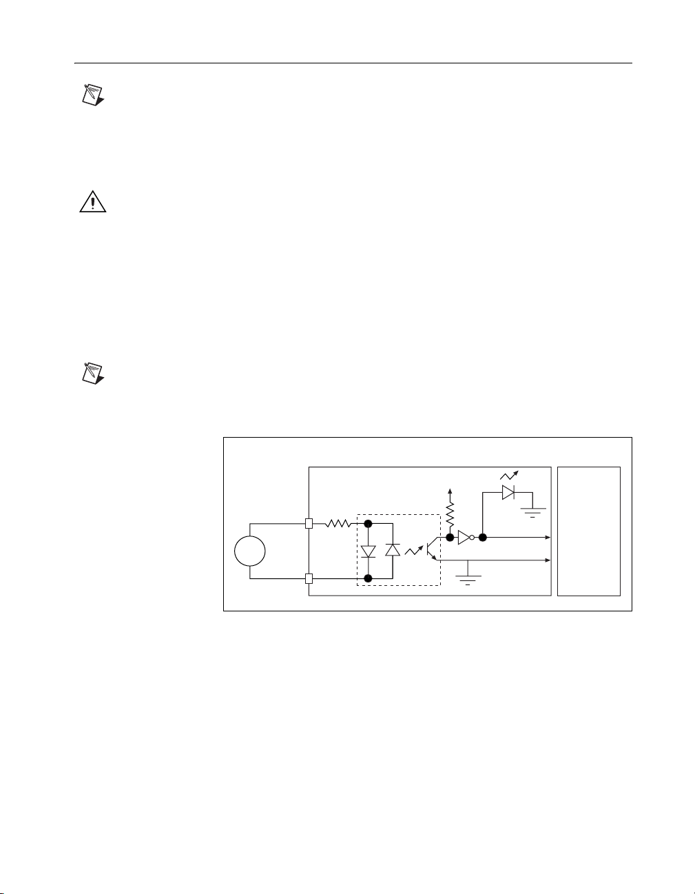
Source
+
–
V
V
IN
COM
SCC-DI01Signal
+5 V
2
3.3 kΩ
1/2 W
1
Figure 1. SCC-DI01 Signal Connections
Status
LED
E Series
P0.(X )
D GND
For information about how to configure the SCC-DI01 module using
NI-DAQmx, refer to the SCC Quick Start Guide.
© National Instruments Corporation 3 SCC-DI01 Isolated Digital Input Module User Guide
 Loading...