

Page 1

SC-2043-SG
User Manual
Eight-Channel Strain Gauge Signal Conditioning Accessory
August 1996 Edition
Part Number 320995B-01
© Copyright 1995, 1996 National Instruments Corporation.
All Rights Reserved.
Page 2

National Instruments Corporate Headquarters
6504 Bridge Point Parkway
Austin, TX 78730-5039
(512) 794-0100
Technical support fax: (800) 328-2203
(512) 794-5678
Branch Offices:
Australia 03 9 879 9422, Austria 0662 45 79 90 0, Belgium 02 757 00 20, Canada (Ontario) 519 622 9310,
Canada (Québec) 514 694 8521, Denmark 45 76 26 00, Finland 90 527 2321, France 1 48 14 24 24,
Germany 089 741 31 30, Hong Kong 2645 3186, Italy 02 48301892, Japan 03 5472 2970, Korea 02 596 7456,
Mexico 95 800 010 0793, Netherlands 0348 433466, Norway 32 84 84 00, Singapore 2265886, Spain 91 640 0085,
Sweden 08 730 49 70, Switzerland 056 20 51 51, Taiwan 02 377 1200, U.K. 01635 523545
Page 3

Limited Warranty
The SC-2043-SG is warranted against defects in materials and workmanship for a period of one year from the date
of shipment, as evidenced by receipts or other documentation. National Instruments will, at its option, repair or
replace equipment that proves to be defective during the warranty period. This warranty includes parts and labor.
A Return Material Authorization (RMA) number must be obtained from the factory and clearly marked on the
outside of the package before any equipment will be accepted for warranty work. National Instruments will pay the
shipping costs of returning to the owner parts which are covered by warranty.
National Instruments believes that the information in this manual is accurate. The document has been carefully
reviewed for technical accuracy. In the event that technical or typographical errors exist, National Instruments
reserves the right to make changes to subsequent editions of this document without prior notice to holders of this
edition. The reader should consult National Instruments if errors are suspected. In no event shall National
Instruments be liable for any damages arising out of or related to this document or the information contained in it.
EXCEPT AS SPECIFIED HEREIN, NATIONAL INSTRUMENTS MAKES NO WARRANTIES, EXPRESS OR IMPLIED,
AND SPECIFICALLY DISCLAIMS ANY WARRANTY OF MERCHANTABILITY OR FITNESS FOR A PARTICULAR
PURPOSE
OF
NATIONAL INSTRUMENTS WILL NOT BE LIABLE FOR DAMAGES RESULTING FROM LOSS OF DATA, PROFITS,
USE OF PRODUCTS, OR INCIDENTAL OR CONSEQUENTIAL DAMAGES, EVEN IF ADVISED OF THE POSSIBILITY
THEREOF
whether in contract or tort, including negligence. Any action against National Instruments must be brought within
one year after the cause of action accrues. National Instruments shall not be liable for any delay in performance due
to causes beyond its reasonable control. The warranty provided herein does not cover damages, defects,
malfunctions, or service failures caused by owner's failure to follow the National Instruments installation, operation,
or maintenance instructions; owner's modification of the product; owner's abuse, misuse, or negligent acts; and
power failure or surges, fire, flood, accident, actions of third parties, or other events outside reasonable control.
. CUSTOMER'S RIGHT TO RECOVER DAMAGES CAUSED BY FAULT OR NEGLIGENCE ON THE PART
NATIONAL INSTRUMENTS SHALL BE LIMITED TO THE AMOUNT THERETOFORE PAID BY THE CUSTOMER.
. This limitation of the liability of National Instruments will apply regardless of the form of action,
Copyright
Under the copyright laws, this publication may not be reproduced or transmitted in any form, electronic or
mechanical, including photocopying, recording, storing in an information retrieval system, or translating, in whole or
in part, without the prior written consent of National Instruments Corporation.
Trademarks
LabVIEW®, NI-DAQ®, RTSI®, DAQCard™, and DAQPad™ are trademarks of National Instruments Corporation.
Product names and company names listed are trademarks or trade names of their respective companies.
Page 4

WARNING REGARDING MEDICAL AND CLINICAL USE
OF NATIONAL INSTRUMENTS PRODUCTS
National Instruments products are not designed with components and testing intended to ensure a level of reliability
suitable for use in treatment and diagnosis of humans. Applications of National Instruments products involving
medical or clinical treatment can create a potential for accidental injury caused by product failure, or by errors on the
part of the user or application designer. Any use or application of National Instruments products for or involving
medical or clinical treatment must be performed by properly trained and qualified medical personnel, and all
traditional medical safeguards, equipment, and procedures that are appropriate in the particular situation to prevent
serious injury or death should always continue to be used when National Instruments products are being used.
National Instruments products are NOT intended to be a substitute for any form of established process, procedure, or
equipment used to monitor or safeguard human health and safety in medical or clinical treatment.
Page 5

Contents
About This Manual
Organization of This Manual ............................................................................................ ix
Conventions Used in This Manual.................................................................................... x
National Instruments Documentation ............................................................................... x
Related Documentation .................................................................................................... xi
Customer Communication ................................................................................................ xi
............................................................................................................... ix
Chapter 1
Introduction
About the SC-2043-SG .................................................................................................. 1-1
What You Need to Get Started ...................................................................................... 1-1
Software Programming Choices .................................................................................... 1-2
Optional Equipment ....................................................................................................... 1-3
Unpacking ...................................................................................................................... 1-4
.......................................................................................................................... 1-1
LabVIEW and LabWindows/CVI Application Software .................................. 1-2
NI-DAQ Driver Software................................................................................... 1-2
Register-Level Programming............................................................................. 1-3
Chapter 2
Installation and Configuration
Installation...................................................................................................................... 2-1
Board Configuration ...................................................................................................... 2-1
Power Supply Selection ..................................................................................... 2-3
Onboard/External Excitation Selection.............................................................. 2-4
Local Excitation Sense Selection....................................................................... 2-5
MIO or MIO E Series Boards ................................................................ 2-5
Lab/1200 Series Boards ......................................................................... 2-6
Bridge Completion Selection............................................................................. 2-7
Chapter 3
Signal Connections
I/O Connector Pin Description....................................................................................... 3-1
Screw Terminal Description .......................................................................................... 3-6
Analog Input Connections ................................................................................. 3-7
Offset Nulling ................................................................................................................ 3-9
Offset Nulling Adjustment................................................................................. 3-9
Nulling Range Adjustment................................................................................. 3-10
Other Connection Considerations .................................................................................. 3-11
............................................................................................................. 3-1
Sensor Connection to the SC-2043-SG.................................................. 3-7
Full-Bridge Connection.............................................................. 3-8
Half-Bridge Connection............................................................. 3-8
Quarter-Bridge Connection........................................................ 3-9
....................................................................................... 2-1
© National Instruments Corporation v SC-2043-SG User Manual
Page 6

Contents
Chapter 4
Theory of Operation
Functional Overview...................................................................................................... 4-1
Bridge Completion Network.......................................................................................... 4-3
Amplification ................................................................................................................. 4-3
Offset Nulling ................................................................................................................ 4-3
Filtering.......................................................................................................................... 4-4
I/O Connectors and Breakout Screw Terminals ............................................................ 4-4
Excitation Voltage Source ............................................................................................. 4-4
Power Supply ................................................................................................................. 4-4
.......................................................................................................... 4-1
Chapter 5
Calibration Procedures
Excitation Adjustment.................................................................................................... 5-1
Onboard Excitation Source ................................................................................ 5-1
External Excitation Source................................................................................. 5-2
Appendix A
Specifications
........................................................................................................................ A-1
..................................................................................................... 5-1
Appendix B
Customer Communication
............................................................................................... B-1
Glossary.................................................................................................................................. G-1
Index ........................................................................................................................................ I-1
SC-2043-SG User Manual vi © National Instruments Corporation
Page 7

Contents
Figures
Figure 1-1. The Relationship between the Programming Environment,
NI-DAQ, and Your Hardware ............................................................................. 1-3
Figure 2-1. SC-2043-SG Parts Locator Diagram ................................................................... 2-2
Figure 3-1. Full-Bridge Connection to the SC-2043-SG........................................................ 3-8
Figure 3-2. Half-Bridge Connection to the SC-2043-SG....................................................... 3-8
Figure 3-3. Quarter-Bridge Connection to the SC-2043-SG.................................................. 3-9
Figure 4-1. SC-2043-SG Block Diagram ............................................................................... 4-2
Tables
Table 2-1. Installation and Cabling Options for the SC-2043-SG........................................ 2-1
Table 2-2. Power Supply Selection....................................................................................... 2-3
Table 2-3. Onboard/External Excitation Jumpers................................................................. 2-4
Table 2-4. Local Excitation Sense Jumper Settings for MIO and MIO E Series Boards ..... 2-5
Table 2-5. Local Excitation Sense Jumper Settings for Lab/1200 Series Boards................. 2-6
Table 2-6. Half-Bridge Completion Jumper Settings ........................................................... 2-7
Table 2-7. Half-Bridge Completion Jumpers and Corresponding Channels ........................ 2-7
Table 2-8. Quarter-Bridge Completion Resistors and Corresponding Channels.................. 2-8
Table 3-1. Pin Assignments for the MIO I/O Connectors .................................................... 3-2
Table 3-2. Pin Assignments for the Lab/1200 I/O Connector .............................................. 3-4
Table 3-3. MIO (J10) I/O Connectors Signal Summary....................................................... 3-5
Table 3-4. Lab/1200 (J9) Signal Summary........................................................................... 3-6
Table 3-5. Screw Terminals J1–J6 Signal Summary ............................................................ 3-7
Table 3-6. Offset Nulling Adjust Potentiometer and Corresponding Channel..................... 3-9
Table 3-7. Nulling Resistor and Corresponding Channel..................................................... 3-10
© National Instruments Corporation vii SC-2043-SG User Manual
Page 8

About This Manual
This manual describes the electrical and mechanical aspects of the SC-2043-SG and contains
information concerning its configuration and operation. The SC-2043-SG is an eight-channel
strain gauge signal conditioning accessory for National Instruments DAQ boards. The
conditioned strain gauge signals are routed directly to the analog input channels of the DAQ
board via a 50-pin connector. The SC-2043-SG also has breakout screw terminals for additional
analog inputs (MIO and MIO E Series boards only), analog outputs, and digital and timing I/O
pins on the DAQ board I/O connector.
Organization of This Manual
The SC-2043-SG User Manual is organized as follows:
• Chapter 1, Introduction, describes the SC-2043-SG, lists what you need to get started with
your SC-2043-SG, describes the optional software and optional equipment, and explains how
to unpack your SC-2043-SG.
• Chapter 2, Installation and Configuration, describes the installation and configuration of
your SC-2043-SG. The topics discussed are connection of the SC-2043-SG to the DAQ
board and switch and jumper configuration for your SC-2043-SG.
• Chapter 3, Signal Connections, describes the signal connections to the SC-2043-SG board.
• Chapter 4, Theory of Operation, contains a functional overview of the SC-2043-SG board
and explains the operation of each functional unit making up the SC-2043-SG.
• Chapter 5, Calibration Procedures, discusses the calibration procedures for the SC-2043-SG.
• Appendix A, Specifications, lists the specifications for the SC-2043-SG.
• Appendix B, Customer Communication, contains forms you can use to request help from
National Instruments or to comment on our products.
• The Glossary contains an alphabetical list and description of terms used in this manual,
including abbreviations, acronyms, metric prefixes, mnemonics, and symbols.
• The Index contains an alphabetical list of key terms and topics used in this manual, including
the page where you can find each one.
© National Instruments Corporation ix SC-2043-SG User Manual
Page 9

About This Manual
Conventions Used in This Manual
The following conventions are used in this manual:
bold italic Bold, italic text denotes a note, caution, or warning.
italic Italic text denotes emphasis, a cross reference, or an introduction to a key
concept.
Lab/1200 Lab/1200 refers to the National Instruments Lab-PC+, DAQPad-1200, and
DAQCard-1200 products unless otherwise noted.
MIO MIO refers to the National Instruments AT-MIO-16/64 and
NB-MIO-16/64 (except the -16H and -DH) DAQ boards unless otherwise
noted.
MIO E MIO E refers to the National Instruments MIO E Series of DAQ boards
unless otherwise noted.
monospace Text in this font denotes text or characters that are to be literally input
from the keyboard, sections of code, programming examples, and syntax
examples. This font is also used for the proper names of disk drives,
paths, directories, programs, subprograms, subroutines, device names,
functions, variables, filenames, and extensions, and for statements and
comments taken from program code.
Abbreviations, acronyms, metric prefixes, mnemonics, symbols, and terms are listed in the
Glossary.
National Instruments Documentation
The SC-2043-SG User Manual is one piece of the documentation set for your system. You could
have any of several types of manuals, depending on the hardware and software in your system.
Use the manuals you have as follows:
• Your DAQ hardware user manuals–These manuals have detailed information about the DAQ
hardware that plugs into or is connected to your computer. Use these manuals for hardware
installation and configuration instructions, specification information about your DAQ
hardware, and application hints.
• Software manuals–Examples of software manuals you might have are the LabVIEW and
LabWindows
system, use either the application software (LabVIEW or LabWindows/CVI) manuals or the
NI-DAQ manuals to help you write your application. If you have a large and complicated
system, it is worthwhile to look through the software manuals before you configure your
hardware.
®
/CVI manual sets and the NI-DAQ manuals. After you set up your hardware
SC-2043-SG User Manual x © National Instruments Corporation
Page 10

About This Manual
• Accessory manuals–If you are using accessory products, read the terminal block and cable
assembly installation guides or accessory board user manuals. They explain how to
physically connect the relevant pieces of the system together. Consult these guides when you
are making your connections.
Related Documentation
The following document contains information that you may find helpful as you read this manual:
• Your DAQ hardware user manual
Customer Communication
National Instruments wants to receive your comments on our products and manuals. We are
interested in the applications you develop with our products, and we want to help if you have
problems with them. To make it easy for you to contact us, this manual contains comment and
configuration forms for you to complete. These forms are in Appendix B, Customer
Communication, at the end of this manual.
© National Instruments Corporation xi SC-2043-SG User Manual
Page 11

Chapter 1 Introduction
This chapter describes the SC-2043-SG, lists what you need to get started with your
SC-2043-SG, describes the optional software and optional equipment, and explains how to
unpack your SC-2043-SG.
About the SC-2043-SG
The SC-2043-SG is an eight-channel signal conditioning board that interfaces strain gauge
signals to National Instruments DAQ boards. Each channel includes half-bridge completion with
jumper disable for full-bridge connections, sockets for quarter-bridge completion resistors,
amplifier gain of 10, buffered single pole 1.6 kHz filter, offset nulling circuit, and screw terminal
connections to accommodate strain gauge bridge measurements. Output voltage excitation leads
and input signal leads are attached at the screw terminals. An onboard excitation voltage source
is provided, along with screw terminal connections for optional (user-supplied) external
excitation, and is common to all channels. The conditioned strain gauge signals are routed to
eight single-ended analog inputs on the DAQ board.
Note: The NB-MIO-16H and AT-MIO-16H series boards have a maximum gain of 8 and
are not intended for interfacing to low-level signals. Therefore, you should not use
these boards with the SC-2043-SG.
The SC-2043-SG has additional breakout screw terminals for convenient signal termination of
additional analog inputs, analog outputs, and digital and timing I/O lines on the DAQ board
interfacing connector.
The SC-2043-SG is a circuitboard assembly that is placed on a workbench or mounted in a 19-in.
rack. The SC-2043-SG draws power from the DAQ board via the 50-pin interfacing connector.
A green LED indicates when the board is powered on.
What You Need to Get Started
To set up and use your SC-2043-SG, you will need the following components:
SC-2043-SG board
SC-2043-SG User Manual
SC-2043-SG screw terminal labels
One of the following software packages and documentation:
LabVIEW for Macintosh
LabVIEW for Windows
LabWindows/CVI for Windows
NI-DAQ for Macintosh
NI-DAQ for PC compatibles
© National Instruments Corporation 1-1 SC-2043-SG User Manual
Page 12

Introduction Chapter 1
One of the following:
SH6850 cable or R6850 cable assembly kit (MIO E Series DAQ board)
NB-1 cable (MIO Series, Lab-PC+, or DAQPad-1200 board)
PR50-50F cable (DAQCard-1200)
Detailed specifications of the SC-2043-SG are in Appendix A, Specifications.
Software Programming Choices
There are several options to choose from when programming your National Instruments DAQ
and SCXI hardware. You can use LabVIEW, LabWindows/CVI, NI-DAQ, or register-level
programming.
LabVIEW and LabWindows/CVI Application Software
LabVIEW and LabWindows/CVI are innovative program development software packages for
data acquisition and control applications. LabVIEW uses graphical programming, whereas
LabWindows/CVI enhances traditional programming languages. Both packages include
extensive libraries for data acquisition, instrument control, data analysis, and graphical data
presentation.
LabVIEW features interactive graphics, a state-of-the-art user interface, and a powerful graphical
programming language. The LabVIEW Data Acquisition VI Library, a series of VIs for using
LabVIEW with National Instruments DAQ hardware, is included with LabVIEW. The
LabVIEW Data Acquisition VI Libraries are functionally equivalent to the NI-DAQ software.
LabWindows/CVI features interactive graphics, a state-of-the-art user interface, and uses the
ANSI standard C programming language. The LabWindows/CVI Data Acquisition Library, a
series of functions for using LabWindows/CVI with National Instruments DAQ hardware, is
included with LabWindows/CVI. The LabWindows/CVI Data Acquisition libraries are
functionally equivalent to the NI-DAQ software.
Using LabVIEW or LabWindows/CVI software will greatly reduce the development time for
your data acquisition and control application.
NI-DAQ Driver Software
The NI-DAQ driver software is included at no charge with all National Instruments DAQ
hardware. NI-DAQ is not packaged with SCXI or accessory products, except for the
SCXI-1200. NI-DAQ has an extensive library of functions that you can call from your
application programming environment. These functions include routines for analog input
(A/D conversion), buffered data acquisition (high-speed A/D conversion), analog output
(D/A conversion), waveform generation, digital I/O, counter/timer operations, SCXI, RTSI,
self calibration, messaging, and acquiring data to extended memory.
NI-DAQ has both high-level DAQ I/O functions for maximum ease of use and low-level DAQ
I/O functions for maximum flexibility and performance. Examples of high-level functions are
streaming data to disk or acquiring a certain number of data points. An example of a low-level
function is writing directly to registers on the DAQ device. NI-DAQ does not sacrifice the
performance of National Instruments DAQ devices because it lets multiple devices operate at
their peak performance.
NI-DAQ also internally addresses many of the complex issues between the computer and the
DAQ hardware such as programming the PC interrupt and DMA controllers. NI-DAQ maintains
a consistent software interface among its different versions so that you can change platforms with
SC-2043-SG User Manual 1-2 © National Instruments Corporation
Page 13
Chapter 1 Introduction
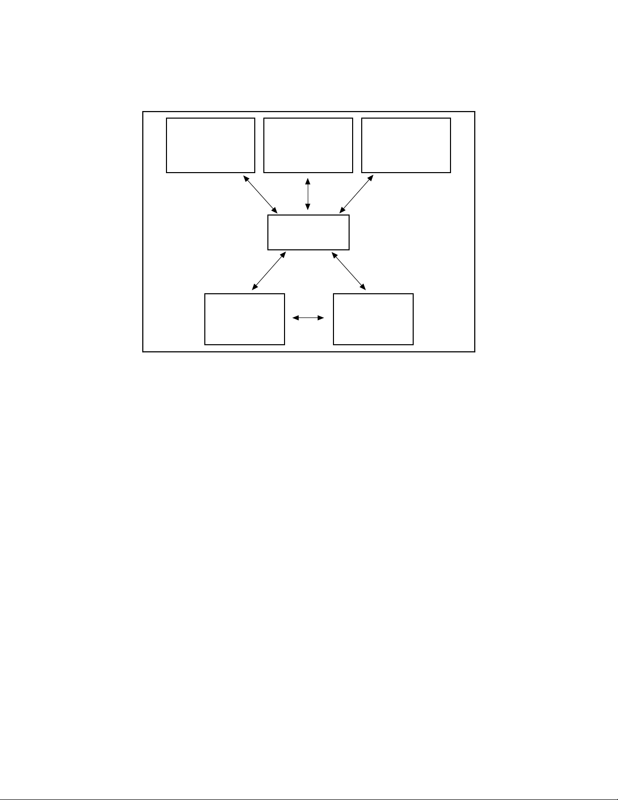
minimal modifications to your code. Figure 1-1 illustrates the relationship between NI-DAQ and
LabVIEW and LabWindows/CVI.
Conventional
Programming
Environment
(PC, Macintosh, or
Sun SPARCstation)
DAQ or
SCXI Hardware
Figure 1-1. The Relationship between the Programming Environment,
NI-DAQ, and Your Hardware
Register-Level Programming
LabVIEW
(PC, Macintosh, or
Sun SPARCstation)
NI-DAQ
Driver Software
LabWindows/CVI
(PC or
Sun SPARCstation)
Personal
Computer
or
Workstation
The final option for programming any National Instruments DAQ hardware is to write registerlevel software. Writing register-level programming software can be very time-consuming and
inefficient and is not recommended for most users.
Even if you are an experienced register-level programmer, consider using NI-DAQ, LabVIEW,
or LabWindows/CVI to program your National Instruments DAQ hardware. Using the NI-DAQ,
LabVIEW, or LabWindows/CVI software is easier than and as flexible as register-level
programming and can save you weeks of development time.
Optional Equipment
Contact National Instruments to order the following optional equipment:
• Single or double height rack-mount kit with acrylic plastic cover
• Single or double height rack-mount kit with metal wraparound cover
• 120 Ω (0.1%, 10 ppm/°C) quarter-bridge completion resistors (eight per package)
• 350 Ω (0.1%, 10 ppm/°C) quarter-bridge completion resistors (eight per package)
© National Instruments Corporation 1-3 SC-2043-SG User Manual
Page 14

Introduction Chapter 1
Unpacking
Your SC-2043-SG board is shipped in an antistatic package to prevent electrostatic damage to
the board. Electrostatic discharge can damage several components on the board. To avoid such
damage in handling the board, take the following precautions:
• Ground yourself via a grounding strap or by holding a grounded chassis such as a computer
chassis.
• Touch the antistatic package to a metal part of your computer chassis before removing the
board from the package.
• Remove the board from the package and inspect the board for loose components or any other
sign of damage. Notify National Instruments if the board appears damaged in any way.
Do not install a damaged board into your computer.
• Never touch the exposed pins of connectors.
SC-2043-SG User Manual 1-4 © National Instruments Corporation
Page 15
Chapter 2 Installation and Configuration
This chapter describes the installation and configuration of your SC-2043-SG. The topics
discussed are connection of the SC-2043-SG to the DAQ board and switch and jumper
configuration for your SC-2043-SG.
Installation
Note: You must power off your computer—and the SC-2043-SG if externally powered—
before installing or making any connection to the SC-2043-SG.
The SC-2043-SG includes two 50-pin cable connectors for signal connection to a DAQ board.
Connect the SC-2043-SG to your DAQ board I/O connector using the appropriate cable and
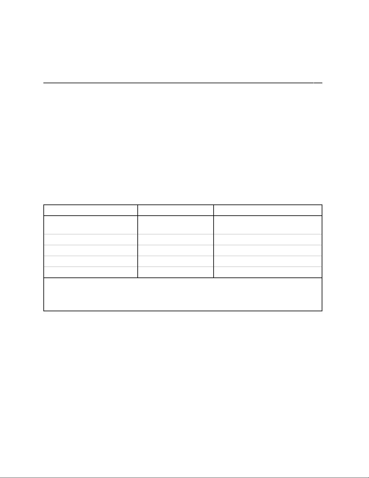
SC-2043-SG 50-pin connector. Table 2-1 lists the required cables and connectors to use with
each DAQ board option.
Table 2-1. Installation and Cabling Options for the SC-2043-SG
DAQ Board Required Cabling SC-2043-SG 50-Pin Connector
68-pin MIO E Series
boards
50-pin MIO boards
100-pin MIO boards
Lab-PC+, DAQPad-1200 NB1 Lab/1200 (J9)
DAQCard-1200 PR50-50F Lab/1200 (J9)
1
To install the SC-2043-SG with any of these boards, refer to the installation guide of the cable kit for instructions.
2
The NB-MIO-16H and AT-MIO-16H boards have a maximum gain of 8 and are not intended for interfacing to low-level
signals. Therefore, you should not use these boards with the SC-2043-SG.
3
The SC-2043-SG connects only to pins 1–50 (ACH<0..15>) of the 100-pin MIO boards.
You can mount the SC-2043-SG in a rack-mount chassis using the mounting holes in the four
corners of the SC-2043-SG board.
The SC-2043-SG is installed. You are now ready to install and configure your software. If you
are using NI-DAQ, LabVIEW, or LabWindows/CVI, refer to the installation instructions to
install and configure your software.
1
2
3
R6850 or SH6850 MIO (J10)
NB1 MIO (J10)
R1005050 MIO (J10)
Board Configuration
Note: You must configure your DAQ board analog channels for NRSE (nonreferenced
single-ended) inputs for use with the SC-2043-SG.
© National Instruments Corporation 2-1 SC-2043-SG User Manual
Page 16

Installation and Configuration Chapter 2
The SC-2043-SG has one slide switch and 12 jumpers that you use to configure your board.
Figure 2-1 shows the switch and jumpers in the parts locator diagram.
1
2 3 4
5
7
12
11
13
8
6
9
10
14
15
16
17
18
20
22
24
30
32
34
26
28
31
19
21
23
25
27
29
33
5455
53
52
51
43
44
50
49
48
45
46
47
36
37
38
39
40
41
42
1 Screen Printed Screw 14 Product Name and 27 R37 41 R53
Terminal Label Assembly Number 28 W12 42 R62
2 J1 15 SW1 29 R51 43 R68
3 J3 16 R9 30 R54 44 W7
4 J5 17 W10 31 R55 45 W6
5 W1 18 J9 32 W13 46 W5
6 J7 19 J10 33 R65 47 W4
7 W3 20 F3 34 R69 48 R6
8 R2 21 R23 35 Serial Number 49 R20
9 J8 22 R17 36 W9 50 R36
10 F1 23 R19 37 R18 51 R52
11 F2 24 W11 38 R30 52 W2
12 R14 25 R33 39 R34 53 J6
13 W8 26 R35 40 R50 54 J4
55 J2
Figure 2-1. SC-2043-SG Parts Locator Diagram
35
SC-2043-SG User Manual 2-2 © National Instruments Corporation
Page 17

Chapter 2 Installation and Configuration
Switch SW1 selects the power supply source for the SC-2043-SG board. Two jumpers, W1 and
W3, select the excitation source for the strain gauge bridges. Jumper W2 routes either the
excitation voltage signal or the channel 0 signal to analog input channel 0 on the DAQ board.
Jumper W8 routes either the excitation voltage signal or an external signal to analog input
channel 8 (for MIO and MIO E Series boards only). Jumpers W4–W7 and W10–W13 configure
the onboard bridge completion network for each of the eight channels for either half-bridge or
full-bridge inputs. Tables 2-2 through 2-6 show the settings for the switch and jumpers.
Power Supply Selection
Set switch SW1 to the INT position to draw power from the +5 V line on the DAQ board. Set
switch SW1 to the EXT position to draw power from an external +5 V power supply connected
to J8. In external power mode, the SC-2043-SG has two fuses, F1 and F2, to limit the current to
1 A at +5 V. The board also has a spare fuse (F3), as shown in Figure 2-1.
Note: If you are using an NB-MIO-16X or a DAQPad-1200 with the SC-2043-SG, you must
use an external +5 V power supply with the SC-2043-SG.
Table 2-2. Power Supply Selection
Switch Description Configuration
INT position—Use this setting to
configure the SC-2043-SG to draw
SW1
INTEXT
power through the DAQ board.
(factory setting)
SW1J8
EXT position—Use this setting to
draw +5 V power from an external
SW1
INTEXT
supply connected to connector J8.
© National Instruments Corporation 2-3 SC-2043-SG User Manual
Page 18

Installation and Configuration Chapter 2
Onboard/External Excitation Selection
If you want to use the onboard voltage excitation source to excite your strain gauge bridges, set
both jumpers W1 and W3 to the INT position. If you want to use an external excitation source,
set both jumpers W1 and W3 to the EXT position and connect your excitation source to
connector J7.
Table 2-3. Onboard/External Excitation Jumpers
Jumpers Description Configuration
J7
W1
W3
INT position—Place jumpers W1
and W3 in this position to provide
excitation voltage from the onboard
excitation source. (factory setting)
EXT position—Place jumpers W1
and W3 in this position to provide
excitation voltage from an external
excitation source connected to
connector J7.
W1, W3
EXT
INT
W1, W3
EXT
INT
SC-2043-SG User Manual 2-4 © National Instruments Corporation
Page 19

Chapter 2 Installation and Configuration
Local Excitation Sense Selection
MIO or MIO E Series Boards
If you are using the SC-2043-SG with an MIO or MIO E Series board, you can locally sense the
exact level of the excitation voltage by routing the excitation voltage (internal or external) to one
of two analog channels, selected by jumpers W8 and W2. Table 2-4 shows these jumper
settings.
Setting jumper W8 to the EX position (the factory setting) routes the excitation voltage to ACH8
so you can use ACH<0..7> for conditioned strain gauge signal inputs. Setting jumper W8 to the
ST position routes an external signal (from the screw terminal labeled 4 in the MIO column, or
ACH8 if you are using the stick-on labels) to ACH8.
Setting jumper W2 to the EX position routes the excitation voltage to ACH0, leaving you
ACH<1..7> for conditioned strain gauge signal inputs. Setting jumper W2 to the CH0 position
(the factory setting) routes the conditioned strain gauge bridge signal (that entered via the CH0±
screw terminals) to ACH0.
Table 2-4. Local Excitation Sense Jumper Settings for MIO and MIO E Series Boards
Jumper Description Configuration
CH0 position—Place the jumper in
this position to route the conditioned
W2
EX
strain gauge bridge signal (that
entered via the CH0± screw
terminals) to ACH0. (factory setting)
W2
EX position—Place the jumper in
CH0
W2
EX
this position to route the excitation
source voltage to ACH0.
CH0
EX position—Place the jumper in
this position to route the excitation
W8
EX ST
source voltage to ACH8. (factory
setting)
W8
ST position—Place the jumper in this
W8
EX ST
position to route an external input
signal to ACH8.
© National Instruments Corporation 2-5 SC-2043-SG User Manual
Page 20

Installation and Configuration Chapter 2
Lab/1200 Series Boards
If you are using the SC-2043-SG with a Lab/1200 Series board, you can locally sense the exact
level of the excitation voltage by routing the excitation voltage (internal or external) to ACH0,
configured by jumper W2. The SC-2043-SG also has jumper W8, which you must also
configure. Table 2-5 shows these jumper settings.
Caution: Although the factory-default setting for jumper W8 is the EX position, you
MUST
set jumper W8 to the ST position if you are using a Lab/1200 Series board.
Failure to do so can damage your Lab/1200 board if your excitation voltage
exceeds 10 V. National Instruments is
NOT liable for any damages resulting from
incorrect configuration of jumper W8. Refer to Table 2-5 for more information.
Setting jumper W8 to the ST position routes DAC1OUT (pin 12 on the Lab/1200 connector) to
the screw terminal labeled 12 in the Lab/1200 column, or DAC1OUT if you are using the stickon labels.
Setting jumper W2 to the EX position routes the excitation voltage to ACH0, leaving you
ACH<1..7> for strain gauge signal measurement. Setting jumper W2 to the CH0 position (the
factory setting) routes the conditioned strain gauge bridge signal (that entered via the CH0±
screw terminals) to ACH0.
Table 2-5. Local Excitation Sense Jumper Settings for Lab/1200 Series Boards
Jumper Description Configuration
CH0 position—Place the jumper in
this position to route the conditioned
W2
EX
strain gauge bridge signal (that
entered via the CH0± screw
terminals) to ACH0. (factory setting)
W2
EX position—Place the jumper in
CH0
W2
EX
this position to route the excitation
source voltage to ACH0.
CH0
EX position—NEVER leave the
jumper in this position. (factory
W8
EX ST
setting)
W8
EX ST
W8
ST position—Always keep the
jumper in this position to route the
DAC1OUT analog output signal
from the Lab/1200 board to a screw
terminal.
SC-2043-SG User Manual 2-6 © National Instruments Corporation
Page 21

Chapter 2 Installation and Configuration
Bridge Completion Selection
Jumpers W4–W7 and W10–W13 select half-bridge or full-bridge configuration for each channel
on the SC-2043-SG. Setting a jumper in the FB position disconnects the half-bridge completion
network from the channel and connects the CHn- screw terminal to the negative input of the
instrumentation amplifier for full-bridge signal inputs. Setting a jumper in the HB position
disconnects the CHn- screw terminal from the instrumentation amplifier and connects the halfbridge completion network to the negative input of the instrumentation amplifier. Table 2-6
shows the jumper settings for the half-bridge completion jumpers and Table 2-7 lists their
corresponding channels.
Table 2-6. Half-Bridge Completion Jumper Settings
Jumper Description Configuration
W4W5
W10
FB position—Use this setting to
select full-bridge completion.
W11
(factory setting)
FB HB
W6 W12
W13W7
HB position—Use this setting to
select half-bridge completion.
Table 2-7. Half-Bridge Completion Jumpers and Corresponding Channels
Channel Jumper
0
1
2
3
4
5
6
7
W7
W6
W5
W4
W13
W12
W11
W10
FB HB
© National Instruments Corporation 2-7 SC-2043-SG User Manual
Page 22

Installation and Configuration Chapter 2
Additionally, there are sockets for eight quarter-bridge completion resistors. When inserted, the
quarter-bridge completion resistors connect to the positive inputs of the instrumentation
amplifiers and the -EXn terminals. To configure a channel for quarter-bridge completion, set the
corresponding bridge completion jumper to the HB position and insert your quarter-bridge
completion resistor into the appropriate sockets. The parts locator diagram, Figure 2-1, shows
where these quarter-bridge completion resistor sockets are located. Table 2-8 lists the quarterbridge completion resistors and corresponding channels.
Table 2-8. Quarter-Bridge Completion Resistors and Corresponding Channels
Channel Resistor
0
1
2
3
4
5
6
7
R52
R36
R20
R6
R54
R37
R23
R9
SC-2043-SG User Manual 2-8 © National Instruments Corporation
Page 23

Chapter 3 Signal Connections
This chapter describes the signal connections to the SC-2043-SG board.
I/O Connector Pin Description
Warning: Connections, including any power signals connected to ground and vice versa, that
exceed any of the maximum input or output signal ratings on the SC-2043-SG and
the DAQ board can damage the SC-2043-SG, the DAQ board, and the computer.
National Instruments is
signal connections.
The SC-2043-SG has two male 50-pin I/O connectors to connect it to a DAQ board. These
connectors, J9 and J10, are labeled Lab/1200 and MIO, respectively. The Lab/1200 connector
(J9) carries the signals between the SC-2043-SG and a Lab/1200 board. The MIO connector
(J10) carries the signals between the SC-2043-SG and an MIO or MIO E Series board. You can
use only one of these connectors to interface to a DAQ board at any time. Figure 2-1 shows the
position of these connectors on the SC-2043-SG board.
NOT liable for any damages resulting from any such
Notes: If you are connecting to an MIO or MIO E Series board, you must use the MIO
connector. If you are connecting to a Lab/1200 board, you must use the Lab/1200
connector. These connectors are
must be careful
Connector W9 is reserved for National Instruments internal use only.
Tables 3-1 and 3-2 show the pin assignments for the SC-2043-SG I/O connectors. These tables
list the pin numbers of the I/O connector and the corresponding signal names for the MIO
connector if you are using an MIO or MIO E Series DAQ board, and for the Lab/1200 connector
if you are using a Lab/1200 Series DAQ board. Tables 3-3 and 3-4 list the MIO and Lab/1200
I/O connector signal summaries, respectively.
NOT to use the wrong connector.
NOT pin-for-pin compatible and, therefore, you
© National Instruments Corporation 3-1 SC-2043-SG User Manual
Page 24

Signal Connections Chapter 3
Table 3-1. Pin Assignments for the MIO I/O Connectors
Pin Numbers MIO Connector Signal
Names
1 AIGND AIGND
2 AIGND AIGND
3 ACH0† ACH0†
4 ACH8 ACH8
5 ACH1† ACH1†
6 ACH9 ACH9
7 ACH2† ACH2†
8 ACH10 ACH10
9 ACH3† ACH3†
10 ACH11 ACH11
11 ACH4† ACH4†
12 ACH12 ACH12
13 ACH5† ACH5†
14 ACH13 ACH13
15 ACH6† ACH6†
16 ACH14 ACH14
17 ACH7† ACH7†
18 ACH15 ACH15
19 AISENSE AISENSE
20 DAC0OUT DAC0OUT
21 DAC1OUT DAC1OUT
22 EXTREF EXTREF
23 AOGND AOGND
24 DGND DGND
25 ADIO0 DIO0
26 BDIO0 DIO4
27 ADIO1 DIO1
28 BDIO1 DIO5
29 ADIO2 DIO2
30 BDIO2 DIO6
31 ADIO3 DIO3
32 BDIO3 DIO7
33 DGND† DGND†
34 +5 V† +5 V†
35 +5 V +5 V
36 SCANCLK SCANCLK
37 †† EXTSTROBE*
MIO E Series I/O Connector
Signal Names
(continues)
SC-2043-SG User Manual 3-2 © National Instruments Corporation
Page 25

Chapter 3 Signal Connections
Table 3-1. Pin Assignments for the MIO I/O Connectors (Continued)
Pin Numbers MIO Connector Signal
Names
38 †† TRIG1
39 †† TRIG2
40 EXTCONV* CONVERT*
41 SOURCE1 GPCTR1_SOURCE
42 GATE1 GPCTR1_GATE
43 OUT1 GPCTR1_OUT
44 †† UPDATE*
45 GATE2 WFTRIG
46 OUT2 STARTSCAN
47 SOURCE5 GPCTR0_SOURCE
48 GATE5 GPCTR0_GATE
49 OUT5 GPCTR0_OUT
50 FOUT FREQ_OUT
† These signals are not routed to screw terminals. All other signals on the I/O connectors are routed directly to
screw terminals (J1–J6) for convenient signal termination.
†† The function of this connector pin varies depending on the type of MIO Series board you have. Refer to your
MIO board user manual for the appropriate pin name.
MIO E Series I/O Connector
Signal Names
© National Instruments Corporation 3-3 SC-2043-SG User Manual
Page 26

Signal Connections Chapter 3
Table 3-2. Pin Assignments for the Lab/1200 I/O Connector
Pin Numbers Lab/1200 Connector
Signal Names
1 ACH0†
2 ACH1†
3 ACH2†
4 ACH3†
5 ACH4†
6 ACH5†
7 ACH6†
8 ACH7†
9 AISENSE
10 DAC0OUT
11 AGND
12 DAC1OUT
13 DGND
14 PA0
15 PA1
16 PA2
17 PA3
18 PA4
19 PA5
20 PA6
21 PA7
22 PB0
23 PB1
24 PB2
25 PB3
26 PB4
27 PB5
28 PB6
29 PB7
30 PC0
31 PC1
32 PC2
33 PC3
34 PC4
35 PC5
36 PC6
37 PC7
(continues)
SC-2043-SG User Manual 3-4 © National Instruments Corporation
Page 27

Chapter 3 Signal Connections
Table 3-2. Pin Assignments for the Lab/1200 I/O Connector (Continued)
Pin Numbers Lab/1200 Connector
Signal Names
38 EXTTRIG
39 EXTUPDATE*
40 EXTCONV*
41 OUTB0
42 GATB0
43 OUTB1
44 GATB1
45 CLKB1
46 OUTB2
47 GATB2
48 CLKB2
49 +5 V†
50 DGND†
† These signals are not routed to screw terminals. All other signals on the I/O connectors are routed directly to
screw terminals (J1–J6) for convenient signal termination.
Table 3-3. MIO (J10) I/O Connectors Signal Summary
Signal Name Pin Number Description
AIGND 2 Analog Input Ground—This pin provides the AC noise current return
point for the analog circuitry and for the onboard excitation supply. It is
also routed to a screw terminal.
AISENSE 19 Analog Input Sense—This pin is the reference node for the conditioned
strain gauge bridge signals. It is also routed to a screw terminal to
provide a reference for analog inputs on channels ACH<8..15>.
AISENSE is directly connected to the excitation supply return and is
earth-grounded. This makes AISENSE a low impedance reference;
therefore, all signals referenced to it MUST be floating.
ACH<0..7> 3, 5, 7, 9, 11,
13, 15, 17
DGND 24
33
+5 V 34 +5 VDC Source—This pin provides DC power for the SC-2043-SG from
Others Others The remaining pins are routed directly to screw terminals to provide easy
Analog Input Channels 0 through 7—These pins carry the conditioned
strain gauge bridge signals (referenced to AISENSE) to the DAQ board.
They are not routed to screw terminals.
Digital Ground—This pin is the reference for the +5 VDC power supply.
It is also routed to a screw terminal to provide a reference for the digital
signals at the screw terminals.
This pin establishes the DC return path for the onboard excitation supply.
It is not routed to a screw terminal.
the MIO or MIO E Series board. It is not routed to a screw terminal.
access to the additional analog, digital, and counter/timer I/O signals of
the DAQ board. Refer to the Signal Connections chapter in your DAQ
board user manual for pin descriptions.
© National Instruments Corporation 3-5 SC-2043-SG User Manual
Page 28

Signal Connections Chapter 3
Table 3-4. Lab/1200 (J9) I/O Connector Signal Summary
Signal Name Pin Number Description
AGND 11 Analog Ground—This pin provides the AC noise current return point for
the analog circuitry and for the onboard excitation supply. It is also
routed to a screw terminal.
AISENSE 9 Analog Input Sense—This pin is the reference node for the conditioned
strain gauge bridge signals. It is also routed to a screw terminal.
AISENSE is directly connected to the excitation supply return and is
earth-grounded. This makes AISENSE a low impedance reference;
therefore, all signals referenced to it MUST be floating.
ACH<0..7> 1–8 Analog Input Channels 0 through 7—These pins carry the conditioned
strain gauge bridge signals (referenced to AISENSE) to the DAQ board.
They are not routed to screw terminals.
DGND 13
50
+5 V 49 +5 VDC Source—This pin provides DC power for the SC-2043-SG from
Others Others The remaining pins are routed directly to screw terminals to provide easy
Digital Ground—This pin is the reference for the +5 VDC power supply.
It is also routed to a screw terminal to provide a reference for the digital
signals at the screw terminals.
This pin establishes the DC return path for the onboard excitation supply.
It is not routed to a screw terminal.
the Lab/1200 board. It is not routed to a screw terminal.
access to the additional analog, digital, and counter/timer I/O signals of
the DAQ board. Refer to the Signal Connections chapter in your DAQ
board user manual for pin descriptions.
Screw Terminal Description
Screw terminal blocks J1–J6, shown in Figure 2-1, provide excitation output and strain gauge
bridge signal inputs, and terminate signals on the MIO and Lab/1200 I/O connectors. Two sets
of labels are silkscreened onto the SC-2043-SG board for these screw terminals—one set for the
MIO connector and the other for the Lab/1200 connector. Notice that only the excitation output
screw terminals, +EXn, -EXn (n is the channel number), and the analog signal input screw
terminals CHn+ and CHn- have signal names. All other screw terminals on terminal blocks
J1–J6 are labeled with the pin numbers of the MIO and Lab/1200 I/O connector pins to which
they are mapped.
Additionally, a sheet of sticker labels printed with signal names for every screw terminal is
included with your SC-2043-SG. This sheet consists of three sets of sticker labels, one set
printed with MIO Series signal names, one set with Lab/1200 Series signal names, and one set
with MIO E Series signal names. You can peel off the appropriate set of sticker labels and apply
them on the SC-2043-SG board over the silkscreened labels by following these steps:
1. Select the set of sticker labels (MIO, Lab/1200, or MIO E Series) that corresponds to the type
of DAQ board to which you are connecting the SC-2043-SG.
2. Peel off each of the three labels and mount them on the SC-2043-SG over the silkscreened
labels. For the Lab/1200 boards, make sure you match the sticker label signal numbers to the
Lab/1200 silkscreened signal numbers on the board.
SC-2043-SG User Manual 3-6 © National Instruments Corporation
Page 29

Chapter 3 Signal Connections
Table 3-5 lists the screw terminals (J1–J6) signal summary.
Table 3-5. Screw Terminals J1–J6 Signal Summary
Signal Name Description
CH<0..7>± Input Channels—These inputs are the input signals for analog channels
0 through 7.
±EX<0..7> Voltage Excitation Outputs—These output signals route the excitation
voltage supply (internal or external) to the sensors connected to these
channels.
Others All other screw terminals provide signal termination for the remaining I/O
lines of the DAQ board, except ACH<0..7>, +5 V, and one DGND line.
Refer to Tables 3-1 and 3-2 for these signal pin numbers.
If you are not using the sticker labels that come in the SC-2043-SG kit, the
numbers silkscreened on the board beside these screw terminals are the
pin numbers of the MIO and Lab/1200 I/O connector pins to which they
are mapped.
There are two additional screw terminal blocks, J7 and J8, shown in Figure 2-1. Screw terminal
block J7 is for external voltage excitation input signals, which hook up to the +EX and -EX
terminals. When the SC-2043-SG is configured for external excitation, the ±EX inputs are
routed directly to the ±EX<0..7> excitation output screw terminals.
Note: The -EX input signal is connected to DGND on the SC-2043-SG. Because this low-
impedance connection can cause a ground loop, which may affect your measurements,
your excitation voltage source
MUST be floating.
Screw terminal block J8 is for external +5 V power inputs, which hook up to the +5 V signal and
ground terminals. When the SC-2043-SG is configured for external power these inputs provide
power to the SC-2043-SG.
Note: The ground input signal is directly connected to DGND on the SC-2043-SG. In order
to avoid a ground loop, which may affect your measurements, your +5 V power supply
MUST be floating.
Analog Input Connections
Sensor Connection to the SC-2043-SG
You can connect strain gauges to the SC-2043-SG in full-bridge, half-bridge, and quarter-bridge
configurations. See Chapter 2, Installation and Configuration, to make sure that you have
configured the SC-2043-SG channels correctly before you connect any sensors to them.
Note: Configure any unused channels for full-bridge connections and short their input screw
terminals (CHn
© National Instruments Corporation 3-7 SC-2043-SG User Manual
±
) to their excitation return screw terminals (-EXn).
Page 30

Signal Connections Chapter 3
Full-Bridge Connection
In this configuration all four elements of the bridge are external to the SC-2043-SG. Four lead
wires connect the full-bridge to screw terminals +EXn, -EXn, CHn+, and CHn-. The pair of
wires connected to +EXn and -EXn provides excitation voltage to the bridge, and the other pair
connected to CHn+ and CHn- senses the output voltage of the bridge. Figure 3-1 shows this
configuration, along with the appropriate half-bridge jumper placement.
Full Bridge
+EX
CHn+
CHn-
-EX
n
n
+EX
FB
HB
Half-Bridge
Completion
Jumper
x10
Half-Bridge
Completion
Reference
Figure 3-1. Full-Bridge Connection to the SC-2043-SG
Half-Bridge Connection
In this configuration only two strain gauges are used. Bridge completion is provided by a half-
bridge completion reference internal to the SC-2043-SG. Three lead wires connect the halfbridge to screw terminals +EXn, -EXn, and CHn+. The pair of wires connected to +EXn and
-EXn provides excitation voltage to the half-bridge, and the other wire connected to CHn+ senses
the output voltage of the half-bridge with respect to the internal half-bridge completion reference.
Figure 3-2 shows this configuration, along with the appropriate half-bridge jumper placement.
Half Bridge
+EX
CHn+
CHn-
-EX
n
n
+EX
FB
HB
Half-Bridge
Completion
Jumper
x10
Half-Bridge
Completion
Reference
Figure 3-2. Half-Bridge Connection to the SC-2043-SG
SC-2043-SG User Manual 3-8 © National Instruments Corporation
Page 31

Chapter 3 Signal Connections
Quarter-Bridge Connection
In this configuration only one strain gauge is used. Bridge completion is provided by the internal
half-bridge completion reference as well as a quarter-bridge completion resistor. This quarterbridge completion resistor is equal in value to the external strain gauge element. Insert your
completion resistor in the appropriate sockets. Two lead wires connect the quarter-bridge strain
gauge to screw terminals +EXn and CHn+. If your strain gauge has three lead wires—two wires
at one end and one at the other end—connect the two wires sharing the same end of the strain
gauge at the CHn+ screw terminal, and connect the single wire end to the +EXn screw terminal.
Figure 3-3 shows this configuration, along with the appropriate quarter-bridge completion
resistor and half-bridge jumper placement.
Quarter Bridge
+EX
n
CHn+
CHn-
-EX
n
Quarter Bridge
Completion Resistor
(User Installed)
+EX
FB
HB
Half-Bridge
Completion
Jumper
x10
Half-Bridge
Completion
Reference
Figure 3-3. Quarter-Bridge Connection to the SC-2043-SG
Offset Nulling
Offset Nulling Adjustment
The SC-2043-SG has circuitry for offset nulling adjustment of Wheatstone bridges. The nulling
circuitry uses the excitation voltage as a reference and operates with full-bridge, half-bridge and
quarter-bridge strain gauge configurations. Each channel has its own nulling circuit, with a
trimming potentiometer to adjust the nulling voltage level, listed in Table 3-6.
Table 3-6. Offset Nulling Adjust Potentiometer and Corresponding Channel
Channel Trimming Potentiometer
0 R62
1 R50
2 R30
3 R14
4 R65
5 R51
6 R33
7 R17
© National Instruments Corporation 3-9 SC-2043-SG User Manual
Page 32

Signal Connections Chapter 3
To null the static voltage offset of the system, including the bridge, use the following procedure:
1. Configure and connect your bridge to the selected channel.
2. Read the channel output.
3. While monitoring the output, rotate the trimming potentiometer wiper with a flathead
screwdriver until you reach 0 V.
You have nulled your system offset and are ready for a measurement.
Nulling Range Adjustment
The nulling range of the offset nulling circuitry is approximately ±5 mV referred to input (RTI),
assuming an excitation voltage of 2.5 V. The nulling circuit of each channel has a resistor which
sets this nulling range. You can change the nulling range of the offset nulling circuitry for each
channel by replacing its nulling resistor with a resistor of another value. Therefore, you can mix
your ranges to accommodate each channel requirement. Table 3-7 lists the nulling resistors and
their corresponding channels.
Table 3-7. Nulling Resistor and Corresponding Channel
Channel Nulling Resistor
0 R68
1 R53
2 R34
3 R18
4 R69
5 R55
6 R35
7 R19
The value of all the nulling resistors on the SC-2043-SG is 47 kΩ. Notice that these resistors are
socketed for easy replacement. These sockets best fit a 1/4 W resistor lead size.
If you want to change the nulling range of any channel, use the following formula to determine
the nulling resistor value you need to achieve your desired nulling range:
REX
≈
null
V RTI
desired nulling range
100
Ω
where:
R
is the nulling resistor value,
null
EX is the excitation voltage (factory-adjusted to 2.5 V),
V
desired nulling range
SC-2043-SG User Manual 3-10 © National Instruments Corporation
RTI is the desired nulling range, referred to input.
Page 33

Chapter 3 Signal Connections
For example, assuming:
EX = 2.5 V
V
desired nulling range
RTI = ±1 mV RTI
Then, using the above formula, the new nulling resistor should have a value of:
R 2.5 V
≈
null
250 k
≈Ω
±
1 mV RTI
100
Ω
Other Connection Considerations
If you are using an MIO or MIO E Series board with 8 additional single-ended analog input
channels, remember that your DAQ board will be configured for NRSE operation and all analog
inputs are referenced to AISENSE (pin 19 on the MIO I/O connector).
Note: AISENSE is ground referenced on the SC-2043-SG. In order to avoid a ground loop,
which may affect your measurements, all analog input signals
For all other input and output signals, refer to the appropriate sections in your DAQ board user
manual for additional signal connection information.
MUST be floating.
© National Instruments Corporation 3-11 SC-2043-SG User Manual
Page 34

Chapter 4 Theory of Operation
This chapter contains a functional overview of the SC-2043-SG board and explains the operation
of each functional unit making up the SC-2043-SG.
Functional Overview
The SC-2043-SG consists of eight channels, each comprising a bridge completion network, an
instrumentation amplifier with a gain of 10, offset nulling, filtering, and screw terminal
connections to accommodate strain gauge bridge measurements. An onboard excitation voltage
source is provided, along with the option of user-supplied external excitation. Additional
breakout screw terminals are also provided for signal termination of analog, digital, and timing
I/O lines on the DAQ board I/O connector.
The key functional components of the SC-2043-SG are:
• Bridge completion network
• Amplification
• Offset nulling
• Filtering
• MIO and Lab/1200 I/O connectors and breakout screw terminals
• Excitation voltage source
• Power supply
The remainder of this chapter describes the theory of operation for each of these components.
© National Instruments Corporation 4-1 SC-2043-SG User Manual
Page 35

Theory of Operation Chapter 4
The block diagram in Figure 4-1 illustrates the key functional components of the SC-2043-SG.
EX0+
CH0+
CH0-
EX0-
EX1+
CH1+
CH1-
EX1-
EX7+
Onboard/External
Excitation
Jumpers
External Excitation
+-
Half-Bridge
Completion
Jumper
Half-Bridge
Completion
Jumper
Internal
+2.5 V
Excitation
x10
x10
Half-Bridge
Completion Reference
Lowpass Filter
(Buffered)
Offset
Nulling
Circuit
Lowpass Filter
(Buffered)
Offset
Nulling
Circuit
±15 V
Local Excitation
Sense Jumper
Power
Converter
External Power
+5 V Gnd
Onboard/External
Power Supply
Selection Switch
ACH0
ACH1
ACH7
DAC1OUT
+5 V+5 V
ACH0
50-Pin I/O Connector for Lab/1200 Series Board
ACH1
ACH7
ACH8
50-Pin I/O Connector for MIO or MIO E Series Board
CH7+
CH7-
EX7-
I/O Screw
Terminals
Quarter-Bridge
Completion Resistor
(User-Installed)
x10
Half-Bridge
Completion
Jumper
Unused Analog, Digital, and Timing I/O Lines of
MIO, MIO E, or Lab/1200 Series Board
Lowpass Filter
(Buffered)
Offset
Nulling
Circuit
Local Excitation
Sense Jumper
Figure 4-1. SC-2043-SG Block Diagram
SC-2043-SG User Manual 4-2 © National Instruments Corporation
Page 36

Chapter 4 Theory of Operation
Bridge Completion Network
The SC-2043-SG provides onboard bridge completion that you can use with half-bridge and
quarter-bridge networks.
The SC-2043-SG has a single half-bridge reference that is common to all channels, consisting of
a resistive divider network of two 2.5 kΩ resistors, with 0.02% ratio tolerance and 2 ppm/°C
tracking temperature coefficient (TCR). Each channel has a jumper that configures the channel
for either half-bridge or full-bridge inputs. When configured for half-bridge inputs, the jumper
connects the half-bridge reference output to the negative input of the instrumentation amplifier in
that channel for half-bridge completion. When configured for full-bridge inputs, the jumper
disconnects the half-bridge reference output from the instrumentation amplifier negative input
and connects the negative input to the CHn- screw terminal for full-bridge signal inputs.
Additionally, sockets are provided for eight quarter-bridge completion resistors. When inserted,
the quarter-bridge completion resistors are connected to the positive inputs of the instrumentation
amplifiers and the -EXn terminals, as shown in the block diagram.
Amplification
Each channel of the SC-2043-SG has an instrumentation amplifier with a fixed gain of 10, to
which the bridge output signals are routed. The instrumentation amplifier inputs are protected
from over-voltages up to ±45 V with the SC-2043-SG powered on and ±30 V powered off.
These amplifiers fulfill two purposes on the SC-2043-SG board. First, they convert differential
input signals into single-ended signals referred to the SC-2043-SG AISENSE node for input
common-mode signal rejection. With this conversion, the SC-2043-SG can extract the bridge
input signals from common-mode noise voltages before the DAQ board samples and converts the
signals. Second, the instrumentation amplifiers amplify input signals, resulting in increased
measurement resolution and accuracy.
Note: If you select the SC-2043-SG as an accessory when you configure your DAQ board
using the NI-DAQ software, NI-DAQ compensates for the gain of 10 by automatically
dividing any input channels 0 through 7 by 10 on the DAQ board.
Configure all unused channels for full-bridge connections and short their inputs to
their respective excitation return screw terminals (-EXn). If the inputs are left opencircuited, the unused channels will saturate, causing the power consumption of the
SC-2043-SG board to increase significantly.
Offset Nulling
The SC-2043-SG has circuitry for offset nulling adjustment of Wheatstone bridges. The nulling
circuitry uses the excitation voltage as a reference and operates with full-bridge, half-bridge and
quarter-bridge strain gauge configurations. Each channel has its own nulling circuit, with a
trimming potentiometer to adjust the nulling voltage level. The nulling circuit of each channel
also has a resistor that sets the nulling range. You can change the nulling range of the offset
nulling circuitry for each channel by replacing its nulling resistor with a resistor of another value.
Therefore, you can mix your ranges to accommodate each channel requirement. The offset
nulling circuitry has the added advantage of nulling the offset voltages of your entire signal path,
including the bridge, the SC-2043-SG channel, and the DAQ board analog input channel.
© National Instruments Corporation 4-3 SC-2043-SG User Manual
Page 37

Theory of Operation Chapter 4
Filtering
Each channel of the SC-2043-SG has a postgain, lowpass filter. This filter is a single-pole,
buffered, RC filter with a cutoff frequency of 1.6 kHz.
I/O Connectors and Breakout Screw Terminals
The outputs of all eight channels are connected to the ACH<0..7> analog input channel pins on
the MIO I/O connector and the Lab/1200 I/O connector. All the remaining pins, except two, on
these connectors are mapped to breakout screw terminals (J1–J6). These two pins are +5 V
(pin 34 on the MIO and pin 49 on the Lab/1200 I/O connectors) and DGND (pin 33 on the MIO
and pin 50 on the Lab/1200 I/O connectors). Refer to Chapter 3, Signal Connections, for the pin
assignments of the I/O connectors and their mapping to the screw terminals.
Excitation Voltage Source
The SC-2043-SG has an onboard excitation voltage source for Wheatstone bridge excitation.
This source is powered by the +5 V power supply and is routed to eight output screw terminal
pairs (±EX<0..7>), one pair per channel. The excitation source provides an adjustable, regulated
voltage output with a range of 1.5 to 2.5 VDC, controlled by a potentiometer (R2), and shortcircuit current limiting (approximately 1 A). The factory-default onboard excitation source
setting is 2.5 V. Screw terminals on J7 can connect an external excitation source of up to
10 VDC to the SC-2043-SG. Two jumpers select whether the onboard excitation source or the
external excitation source is routed to the output screw terminal pairs ±EX<0..7>. The offset
nulling circuitry also uses the excitation source output as a reference.
You can locally sense the exact level of the excitation voltage by routing the excitation voltage
via jumpers W2 and W8 to ACH0 or ACH8 of the MIO board or to ACH0 on a Lab/1200 board.
Refer to Chapter 2, Installation and Configuration, for further information on excitation source
configuration.
Note: There is
external excitation inputs. Therefore, if you select external excitation, you
ensure that your excitation supply does not exceed 10 V and is current-limited.
NO onboard overvoltage protection and current limiting protection for the
MUST
Power Supply
The SC-2043-SG contains an onboard power switch (SW1) to either power the SC-2043-SG
from the DAQ board or draw power from an external +5 V supply. Fuses F1 and F2 limit the
external +5 V power supply input to 1A at +5 V. The SC-2043-SG also has a spare fuse, F3, as
shown in Figure 2-1. From the +5 V power supply, an onboard DC-DC converter generates a
±15 V source, which is used to power the analog circuitry. The +5 V power supply also powers
the onboard excitation supply. A green LED indicates that the board is receiving power.
SC-2043-SG User Manual 4-4 © National Instruments Corporation
Page 38

Chapter 5 Calibration Procedures
This chapter discusses the calibration procedures for the SC-2043-SG board.
Excitation Adjustment
Onboard Excitation Source
The excitation voltage source on the SC-2043-SG is factory-adjusted to 2.5 V ±0.5%. This
circuit has one potentiometer (R2) that you must adjust to change the excitation voltage level on
all eight output channels.
Note: Because the offset nulling circuitry uses the excitation voltage as a reference, if you
want to change the excitation voltage level or you are using external excitation, you
MUST complete your excitation voltage level adjustments before adjusting the offset
nulling circuitry. If you do not, you will have to readjust the offset nulling voltage
levels on all channels.
If you want to readjust the onboard excitation voltage level to a different value, you must
perform the following steps:
1. If you are using a rack-mount kit, remove the cover to expose the calibration pot.
2. Configure all your strain gauge bridges to the desired SC-2043-SG channels so that the
excitation voltage source is calibrated with the exact bridge load it must supply. Refer to
Chapter 3, Signal Connections, for more information.
Note: Remember to short the input terminals (CHn
negative excitation output terminal (-EXn).
3. Select and read the channel that is configured for local excitation sensing. If you have not
configured the SC-2043-SG for local excitation sensing, refer to Chapter 2, Installation and
Configuration, for more information.
4. Adjust the potentiometer (R2) wiper with a flathead screwdriver until the voltage you are
monitoring reaches the exact level desired.
5. Replace the rack-mount chassis cover, if used.
±
) of any unused channel to its
© National Instruments Corporation 5-1 SC-2043-SG User Manual
Page 39

Calibration Procedures Chapter 5
External Excitation Source
You can connect an external excitation source of up to 10 VDC to screw terminal block J7 on the
SC-2043-SG. If you are using an external excitation source, you must perform the following
steps.
1. If you are using a rack-mount kit, remove the cover.
Caution: If you are using the SC-2043-SG with a Lab/1200 board, you MUST set jumper
W8 to the ST position. Failure to do so can damage your Lab/1200 board if
your excitation voltage exceeds 10 V. National Instruments is
any damages resulting from incorrect configuration of jumper W8. Refer to
Table 2-5 and Chapter 2, Configuration and Installation, for more information.
2. Configure the SC-2043-SG for external excitation so that your excitation source is connected
to screw terminal block J7. Refer to Chapter 2, Installation and Configuration, and
Chapter 3, Signal Connections, for more information.
3. Configure all your strain gauge bridges to the desired SC-2043-SG channels so that the
excitation voltage source is calibrated with the exact bridge load it must supply.
NOT liable for
Note: Remember to short the input terminals (CHn
±
) of any unused channel to its
negative excitation output terminal (-EXn).
4. Select and read the channel that is configured for local excitation sensing. If you have not
configured the SC-2043-SG for local excitation sensing, refer to Chapter 2, Installation and
Configuration, for more information.
5. Adjust your excitation source output level until the voltage you are monitoring reaches the
exact level desired. Do
NOT exceed 10 VDC.
6. Replace the rack-mount chassis cover, if used.
SC-2043-SG User Manual 5-2 © National Instruments Corporation
Page 40

Appendix A Specifications
This appendix lists the specifications for the SC-2043-SG. These are typical at 25° C unless otherwise noted.
Analog Input
Input Characteristics
Number of channels .................................................... 8 differential
Input signal ranges ...................................................... ±1 V (fixed gain of 10 on each channel)
Max working voltage (signal + common mode)......... Each input should remain within ±11 V of ground
Overvoltage protection................................................ ±45 V powered on, ±30 V powered off
Inputs protected.................................................... CH<0..7>±
Transfer Characteristics
Nonlinearity ................................................................ ±0.01% FSR
Gain error .................................................................... ±0.15% of reading max
Amplifier Characteristics
Input impedance
Normal powered on.............................................. 10 GΩ
Powered off or overload....................................... 5.2 kΩ
Input bias current ........................................................ ±2.5 nA
Input offset current...................................................... ±1.5 nA
CMRR ......................................................................... 93 dB min
Output range................................................................ ±11 V
Dynamic Characteristics
Bandwidth ................................................................... 1.6 kHz (single-pole RC filter)
System noise................................................................ 5 µVrms (referred to input)
Stability
Recommended warm-up time ..................................... 10 minutes
Offset temperature coefficient..................................... ±3.5 µV/°C (referred to input)
Gain temperature coefficient....................................... ±10 ppm/°C
Excitation
Channels...................................................................... 1, connected to 8 screw terminal pairs
Level............................................................................ 2.5 V, ±0.5% (adjustable from 1.5 to 2.5 V)
Current drive1.............................................................. 167 mA at 2.5 V
Drift............................................................................. ±480 ppm/°C
1
Excitation current drive assumes eight full-bridge 120 Ω strain gauges.
© National Instruments Corporation A-1 SC-2043-SG User Manual
Page 41

Specifications Appendix A
Bridge type .................................................................. Half or full (jumper-selectable); with sockets for quarter-
bridge completion
Bridge completion....................................................... Two 2.5 kΩ, ±0.02% ratio tolerance
(±2 ppm/°C tracking TCR resistors)
Offset nulling range .................................................... ±5 mV, referred to input
Power Requirement (from DAQ Board)
+5 VDC (±10 %)
Using external excitation ............................................ 570 mA
Using internal 2.5 V excitation ................................... 600–770 mA
2
3
Physical
Dimensions.................................................................. 4.6 by 20.1 by 12.4 cm (1.8 by 7.9 by 4.9 in.)
I/O connectors
I/O signals ............................................................ 72 labeled screw terminals
DAQ board connector .......................................... Two 50-pin ribbon-cable connectors
Environment
Operating temperature................................................. 0° to 50° C
Storage temperature .................................................... -20° to 75° C
Relative humidity ........................................................ 5% to 90% noncondensing
2
Power requirements assume all eight inputs are used or shorted to their respective excitation return (-EXn) screw terminals.
Open-circuited inputs will increase power requirements.
3
When using internal excitation, the power requirement will depend on number and type of strain gauges. The maximum power
requirement listed (770 mA) assumes eight 120 Ω full-bridge inputs. The minimum power requirement listed (600 mA)
assumes one 350 Ω half-bridge input.
SC-2043-SG User Manual A-2 © National Instruments Corporation
Page 42

Appendix B Customer Communication
For your convenience, this appendix contains forms to help you gather the information necessary
to help us solve technical problems you might have as well as a form you can use to comment on
the product documentation. Filling out a copy of the Technical Support Form before contacting
National Instruments helps us help you better and faster.
National Instruments provides comprehensive technical assistance around the world. In the U.S.
and Canada, applications engineers are available Monday through Friday from 8:00 a.m. to
6:00 p.m. (central time). In other countries, contact the nearest branch office. You may fax
questions to us at any time.
Corporate Headquarters
(512) 795-8248
Technical support fax: (800) 328-2203
(512) 794-5678
Branch Offices Phone Number Fax Number
Australia 03 9 879 9422 03 9 879 9179
Austria 0662 45 79 90 0 0662 45 79 90 19
Belgium 02 757 00 20 02 757 03 11
Canada Ontario) 519 622 9310 519 622 9311
Canada (Quebec) 514 694 8521 514 694 4399
Denmark 45 76 26 00 45 76 71 11
Finland 90 527 2321 90 502 2930
France 1 48 14 24 24 1 48 14 24 14
Germany 089 741 31 30 089 714 60 35
Hong Kong 2645 3186 2686 8505
Italy 02 48301892 02 48301915
Japan 03 5472 2970 03 5472 2977
Korea 02 596 7456 02 596 7455
Mexico 95 800 010 0793 5 520 3282
Netherlands 03480 33466 03480 30673
Norway 32 84 84 00 32 84 86 00
Singapore 2265886 2265887
Spain 91 640 0085 91 640 0533
Sweden 08 730 49 70 08 730 43 70
Switzerland 056 20 51 51 056 20 51 55
Taiwan 02 377 1200 02 737 4644
U.K. 01635 523545 01635 523154
© National Instruments Corporation B-1 SC-2043-SG User Manual
Page 43

Technical Support Form
Photocopy this form and update it each time you make changes to your software or hardware, and use the completed
copy of this form as a reference for your current configuration. Completing this form accurately before contacting
National Instruments for technical support helps our applications engineers answer your questions more efficiently.
If you are using any National Instruments hardware or software products related to this problem, include the
configuration forms from their user manuals. Include additional pages if necessary.
Name
Company
Address
Fax ( ) Phone ( )
Computer brand Model Processor
Operating system
Speed MHz RAM MB Display adapter
Mouse yes no Other adapters installed
Hard disk capacity MB Brand
Instruments used
National Instruments hardware product model Revision
Configuration
National Instruments software product Version
Configuration
The problem is
List any error messages
The following steps will reproduce the problem
Page 44

SC-2043-SG Hardware and Software
Configuration Form
Record the settings and revisions of your hardware and software on the line to the right of each item. Complete a
new copy of this form each time you revise your software or hardware configuration, and use this form as a
reference for your current configuration. Completing this form accurately before contacting National Instruments
for technical support helps our applications engineers answer your questions more efficiently.
National Instruments Products
• DAQ Hardware Revision _________________________________________________
• Interrupt Level of Hardware _________________________________________________
• DMA Channels of Hardware _________________________________________________
• Base I/O Address of Hardware _________________________________________________
• NI-DAQ Version _________________________________________________
Other Products
• Computer Make and Model _________________________________________________
• Microprocessor _________________________________________________
• Clock Frequency _________________________________________________
• Type of Video Board Installed _________________________________________________
• Operating System _________________________________________________
• Operating System Version _________________________________________________
• Operating System Mode _________________________________________________
• Programming Language _________________________________________________
• Programming Language Version _________________________________________________
• Other Boards in System _________________________________________________
• Base I/O Address of Other Boards _________________________________________________
• DMA Channels of Other Boards _________________________________________________
• Interrupt Level of Other Boards _________________________________________________
Page 45

Documentation Comment Form
National Instruments encourages you to comment on the documentation supplied with our products. This
information helps us provide quality products to meet your needs.
Title: SC-2043-SG User Manual
Edition Date: August 1996
Part Number: 320995B-01
Please comment on the completeness, clarity, and organization of the manual.
If you find errors in the manual, please record the page numbers and describe the errors.
Thank you for your help.
Name
Title
Company
Address
Phone ( )
Mail to: Technical Publications Fax to: Technical Publications
National Instruments Corporation National Instruments Corporation
6504 Bridge Point Parkway, (512) 794-5678
Austin, TX 78730-5039
Page 46

Glossary
___________________________________________________
Prefix Meaning Value
12
p- picon- nanoµ- micro-
m- milli-
k- kilo-
M- mega-
˚ degrees
Ω ohms
+5 V +5 V signal
A amperes
ACH# DAQ board analog input channel number
A/D analog-to-digital
AGND analog ground signal
AIGND analog input ground signal
AISENSE analog input sense signal
AOGND analog output ground
C Celsius
CHn± module positive or negative input channel number
DAC digital-to-analog converter
DAC#OUT digital-to-analog converter output signal
DAQ data acquisition
DC direct current
DGND digital ground
DIO digital input-output
±EX voltage excitation input signals
±EXn positive or negative voltage excitation output channels
EXT external
EXTREF external reference signal
EXTSTROBE* external strobe signal
FB full bridge
HB half bridge
Hz hertz
in. inches
INT internal
I/O input/output
LED light-emitting diode
m meters
MB megabytes
10
10
10
10
10
10
-
9
-
6
-
3
-
3
6
© National Instruments Corporation G-1 SC-2043-SG User Manual
Page 47

Glossary
NRSE nonreferenced single-ended
ppm parts per million
RAM random-access memory
RC resistance-capacitance
rms root mean square
RTI referred to input
s seconds
SCANCLK scan clock signal
ST screw terminal
TCR temperature coefficient
tempco temperature coefficient
V volts
VI virtual instrument
VDC volts direct current
Vrms volts, root mean square
SC-2043-SG User Manual G-2 © National Instruments Corporation
Page 48

Index
Numbers/Symbols
+5 V signal
Lab/1200 (J9) connector summary
(table), 3-6
MIO (J10) connector summary
(table), 3-5
power supply, 4-4
fuses, 4-4
B
block diagram of SC-2043-SG, 4-2
board configuration. See configuration.
bridge completion network, 4-3
breakout screw terminals (J1–J6), 4-4
C
A
ACH<0..7> signal
Lab/1200 (J9) connector summary
(table), 3-6
MIO (J10) connector summary
(table), 3-5
AGND signal
Lab/1200 (J9) connector summary
(table), 3-6
AIGND signal
MIO (J10) connector summary
(table), 3-5
AISENSE signal
Lab/1200 (J9) connector summary
(table), 3-6
MIO (J10) connector summary
(table), 3-5
single-ended analog input, 3-11
analog input specifications
amplifier characteristics, A-1
dynamic characteristics, A-1
input characteristics, A-1
stability, A-1
transfer characteristics, A-1
analog input connections, 3-7 to 3-9
sensor connection, 3-7
full-bridge connection, 3-8
illustration, 3-8
half-bridge connection, 3-8
illustration, 3-8
quarter-bridge connection, 3-9
illustration, 3-9
cabling options, 2-1
calibration procedures
excitation adjustment, 5-1
external excitation source, 5-1
onboard excitation source, 5-2
configuration
bridge completion selection, 2-7
half-bridge channels (table), 2-7
half-bridge jumper settings
(table), 2-7
quarter-bridge resistors and channels
(table), 2-8
local excitation sense selection
MIO or MIO E Series boards, 2-5
jumper settings (table), 2-5
Lab/1200 Series boards, 2-6
jumper settings (table), 2-6
onboard/external excitation
selection, 2-4
jumper settings (table), 2-4
parts locator diagram, 2-2
power supply selection, 2-3
jumper settings (table), 2-3
connectors Lab/1200 (J9) and MIO (J10)
overview, 3-1, 4-4
Lab/1200 (J9) pin assignments
(table), 3-4
signal summary (table), 3-6
MIO (J10) pin assignments (table), 3-2
signal summary (table), 3-5
customer communication, xi, B-1
© National Instruments Corporation I-1 SC-2043-SG User Manual
Page 49

Index
D
DGND signal
MIO (J10) connector summary
(table), 3-5
Lab/1200 (J9) connector summary
(table), 3-6
documentation
conventions used in manual, x
National Instruments documentation, x
organization of manual, ix
related documentation, xi
E
environment specifications, A-2
equipment, optional, 1-3
excitation specifications, A-1
excitation adjustment, 5-1
external excitation source, 5-1
onboard excitation source, 5-2
F
filtering, 4-4
fuse, 2-3, 4-4
J
J9 (Lab/1200) and J10 (MIO) connectors.
See connectors Lab/1200 (J9) and (J10).
jumpers and switches. See configuration.
L
LabVIEW and LabWindows/CVI
application software, 1-2
M
manual. See documentation.
O
offset nulling, 3-9, 4-3
adjustment, 3-9
table, 3-9
nulling range adjustment, 3-10
table, 3-10
operation of SC-2043-SG. See theory
of operation.
H
hardware calibration.
See calibration procedures.
I
input connectors signal summary (table), 3-4
input mode selection, 2-7
installation, 2-1
cabling options (table), 2-1
unpacking the SC-2043-SG, 1-4
instrumentation amplifiers, 4-3
SC-2043-SG User Manual I-2 © National Instruments Corporation
P
parts locator diagram, 2-2
physical specifications, A-2
pin assignments for I/O connectors J9 and
J10 (table), 3-2, 3-4
power-on sequence, 2-8
power supply
description, 4-4
fuses, 4-4
specifications, A-2
R
register-level programming, 1-3
Page 50

S
SC-2043-SG
block diagram, 4-2
features, 1-1
I/O connectors (J9 and J10)
(tables), 3-2, 3-4
optional equipment, 1-3
screw terminal (J1–J6) description, 3-6
table, 3-7
software programming choices
LabVIEW and LabWindows/CVI
application software, 1-2
NI-DAQ driver software, 1-2 to 1-3
register-level programming, 1-4
unpacking, 1-4
what you need to get started, 1-1
table, 2-4
signal connections
analog signal inputs, 3-7 to 3-9
sensor connection, 3-7
full-bridge connection, 3-8
illustration, 3-8
half-bridge connection, 3-8
illustration, 3-8
quarter-bridge connection, 3-9
illustration, 3-9
connections exceeding maximum ratings
(warning), 3-1
I/O connectors J9 and J10 (tables), 3-2
and 3-4
offset nulling, 3-9, 4-3
adjustment, 3-9
table, 3-9
nulling range adjustment, 3-10
table, 3-10
other connection considerations, 3-11
output connectors (J9 and J10) signal
summary (table), 3-5 to 3-6
screw terminal (J1–J6) description, 3-6
table, 3-7
software calibration.
See calibration procedures.
software programming choices
LabVIEW and LabWindows/CVI
application software, 1-2
NI-DAQ driver software, 1-2
Index
register-level programming, 1-3
specifications
analog input
amplifier characteristics, A-1
dynamic characteristics, A-1
input characteristics, A-1
stability, A-1
transfer characteristics, A-1
environment, A-2
physical, A-2
power requirements, A-2
T
technical support, B-1
theory of operation
amplification, 4-3
block diagram, 4-2
bridge completion network, 4-3
excitation voltage source, 4-4
filtering, 4-4
functional overview, 4-1
offset nulling, 4-3
power supply, 4-6
U
unpacking the SC-2043-SG, 1-4
© National Instruments Corporation I-3 SC-2043-SG User Manual
 Loading...