

Page 1
GETTING STARTED GUIDE
sbRIO-9860
Non-Enclosed, 2-Port, C Series Vehicle
Multiprotocol Interface Module
Page 2
This document describes how to connect to the sbRIO-9860.
Note Before you begin, complete the software and
hardware installation procedures in your chassis
documentation.
Note The guidelines in this document are specific to
the sbRIO-9860. The other components in the system
might not meet the same safety ratings. Refer to the
documentation for each component in the system to
determine the safety and EMC ratings for the entire
system. Refer to the sbRIO-9860 Safety,
Environmental, and Regulatory Information for safety
and EMC information specific to the sbRIO-9860
module.
Note The sbRIO-9860 must be installed inside a
suitable shielded enclosure prior to use.
Connecting the sbRIO-9860
The sbRIO-9860 has two ports for connecting to transceiver
cables (required to connect to the CAN/LIN bus) and a twoposition connector for use with an external power supply.
2 | ni.com | sbRIO-9860 Getting Started Guide
Page 3
For more information about transceiver cables, refer to the
Transceiver Cable page on ni.com.
The sbRIO-9860 requires an external power supply of +9 V to
+30 V to power the transceiver cables. Supply power to the
sbRIO-9860 V
connector on the module front panel using the
SUP
supplied power cable. The exposed lead wires at the end of the
power cable are routed as follows: black wire—COM, red wire—
V
. The power cable lead wires may be daisy-chained to the
SUP
controller power port when the controller supply voltage is in the
appropriate range.
Note Power on V
is required for transceiver cable
SUP
operation.
Note When using more than four transceiver cables
with your CompactRIO chassis, refer to the Transceiver
Cable page on ni.com for mounting guidelines to limit
the thermal impact to your CompactRIO system.
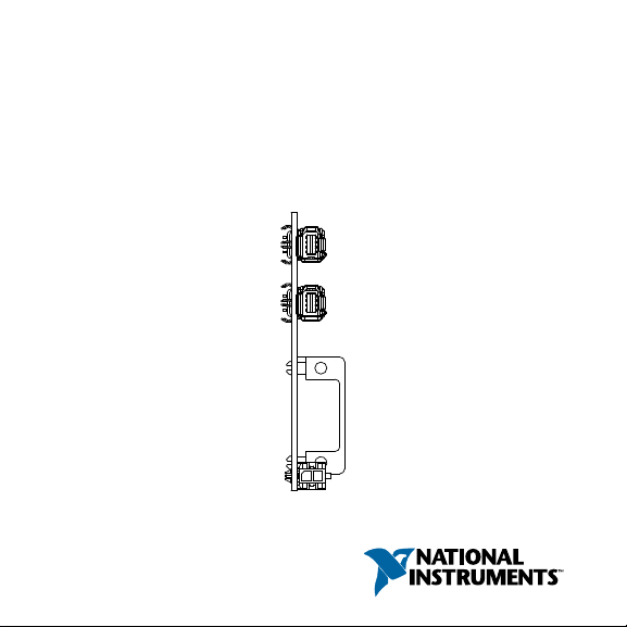
sbRIO-9860 Hardware Overview
The sbRIO-9860 is a two-port C Series board based on the XNET
architecture. Users can choose the physical bus protocol by
sbRIO-9860 Getting Started Guide | © National Instruments | 3
Page 4

plugging in the corresponding transceiver cable. The sbRIO-9860
Ext Pwr
Supply
Required
Controller
COM
V
sup
+
_
Pwr Sup
Controller
Port 1
Port 2
Transceiver
Cable
Transceiver
Cable
supports hot-swapping of transceiver cables and can detect and
identify transceiver cable types.
For more information about transceiver cables, refer to the
Transceiver Cable page on ni.com.
Figure 1. sbRIO-9860 Hardware Overview
4 | ni.com | sbRIO-9860 Getting Started Guide
Page 5

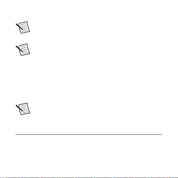
Inserting and Removing the NI-XNET
Push Lock
Ejector Forward
Pull Cable
Transceiver Cable
The NI-XNET Transceiver Cable connects to a host device with
an active latching connector. To connect the NI-XNET
Transceiver Cable to a host device, push the connector assembly
into the host receptacle until the internal latch snaps into position.
The latch emits an audible click when engaged. To remove the
NI-XNET Transceiver Cable, push the lock ejector forward to
disengage the latch and simultaneously pull the NI-XNET
Transceiver Cable, as shown in the following figure.
Figure 2. Inserting and Removing the NI-XNET Transceiver Cable
sbRIO-9860 Getting Started Guide | © National Instruments | 5
Page 6

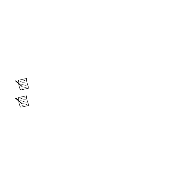
Inserting and Removing the Power Cable
Pull Power
Cable
Push Lock
Ejector Down
The sbRIO-9860 connects to the provided power cable with an
active latching connector. To connect the power cable, push the
end of the power cable into the two-position connector until the
internal latch snaps into position. The latch emits an audible click
when engaged.
To remove the power cable, push the lock ejector down to
disengage the latch and simultaneously pull the power cable
away from the module, as shown in the following figure.
Figure 3. Removing the Power Cable
6 | ni.com | sbRIO-9860 Getting Started Guide
Page 7

Worldwide Support and Services
The NI website is your complete resource for technical support.
At ni.com/support, you have access to everything from
troubleshooting and application development self-help resources
to email and phone assistance from NI Application Engineers.
Visit ni.com/services for information about the services NI offers.
Visit ni.com/register to register your NI product. Product
registration facilitates technical support and ensures that you
receive important information updates from NI.
NI corporate headquarters is located at
11500 North Mopac Expressway, Austin, Texas, 78759-3504. NI
also has offices located around the world. For support in the
United States, create your service request at ni.com/support or
dial 1 866 ASK MYNI (275 6964). For support outside the
United States, visit the Worldwide Offices section of ni.com/
niglobal to access the branch office websites, which provide up-
to-date contact information.
sbRIO-9860 Getting Started Guide | © National Instruments | 7
Page 8

Information is subject to change without notice. Refer to the NI Trademarks and Logo Guidelines
at ni.com/trademarks for information on NI trademarks. Other product and company names
mentioned herein are trademarks or trade names of their respective companies. For patents
covering NI products/technology, refer to the appropriate location: Help»Patents in your software,
the patents.txt file on your media, or the National Instruments Patent Notice at ni.com/
patents. You can find information about end-user license agreements (EULAs) and third-par ty
legal notices in the readme file for your NI product. Refer to the Export Compliance Information at
ni.com/legal/export-compliance for the NI global trade compliance policy and how to obtain
relevant HTS codes, ECCNs, and other import/export data. NI MAKES NO EXPRESS OR
IMPLIED WARRANTIES AS TO THE ACCURACY OF THE INFORMATION CONTAINED
HEREIN AND SHALL NOT BE LIABLE FOR ANY ERRORS. U.S. Government Customers: The
data contained in this manual was developed at private expense and is subject to the applicable
limited rights and restricted data rights as set forth in FAR 52.227-14, DFAR 252.227-7014, and
DFAR 252.227-7015.
© 2019 National Instruments. All rights reserved.
378074A-01 June 26, 2019
 Loading...