

Page 1
USER MANUAL AND SPECIFICATIONS
sbRIO RMC Interface Connector
ENET 1
Connector
C Series
Module
3.3 V
Digital I/O
5 V
Power Supply
x 24
sbRIO-9698
One-Slot C Series and Secondary Ethernet RIO Mezzanine Card
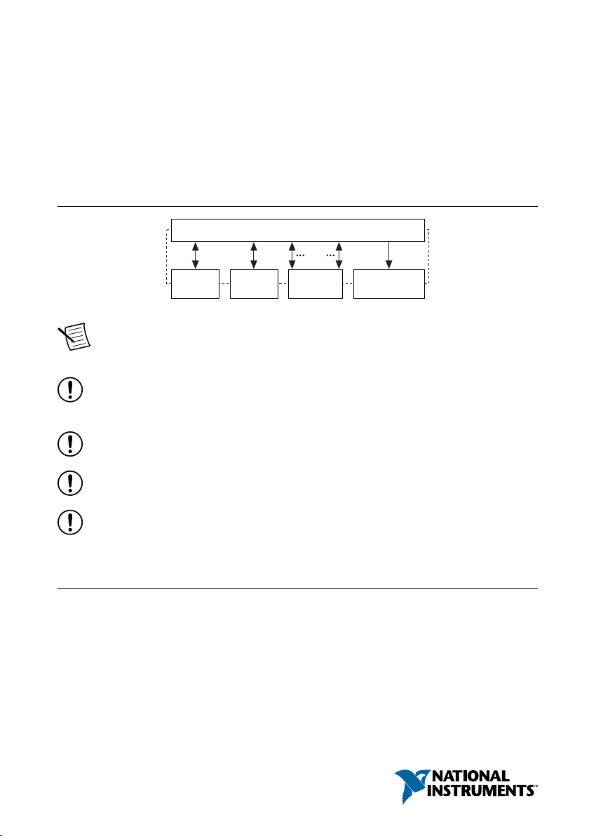
The sbRIO-9698 one-slot C Series RIO Mezzanine Card is an accessory you can use to
connect one board-only C Series module to the NI sbRIO-9607/9627. The sbRIO-9698
includes an Ethernet port for Ethernet communication or EtherCAT master functionality.
Figure 1. sbRIO-9698 Block Diagram
Note Board-only C Series modules are designated sbRIO. For example, the
NI 9219 is the enclosed C Series module and the sbRIO-9219 is the board-only
version of the module.
Notice NI makes no electromagnetic compatibility (EMC) or CE marking
compliance claims for the sbRIO-9698. The end-product supplier is responsible for
conformity to any and all compliance requirements.
Notice The sbRIO-9698 must be installed inside a suitable enclosure prior to use.
Hazardous voltages may be present.
Notice Follow proper ESD precautions to ensure you are grounded before
installing hardware.
Notice The protection provided by the sbRIO-9698 can be impaired if the
sbRIO-9698 is used in a manner not described in this document.
Verifying the Kit Contents
Verify that the following items are included in the sbRIO-9698 kit.
Page 2
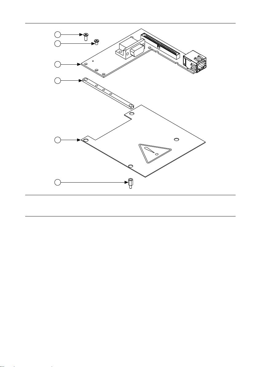
Figure 2. sbRIO-9698 Kit Contents
4
3
2
1
6
5
1. M3 × 7 mm Silver Low-Profile Screw (x4)
2. M3 × 4 mm Black Low-Profile Screw (x6)
3. sbRIO-9698
2 | ni.com | sbRIO-9698 User Manual and Specifications
4. C Series Module Suppor t Bracket (x2)
5. Isolator Sheet
6. M3 × 7 mm Standoff (x4)
Page 3
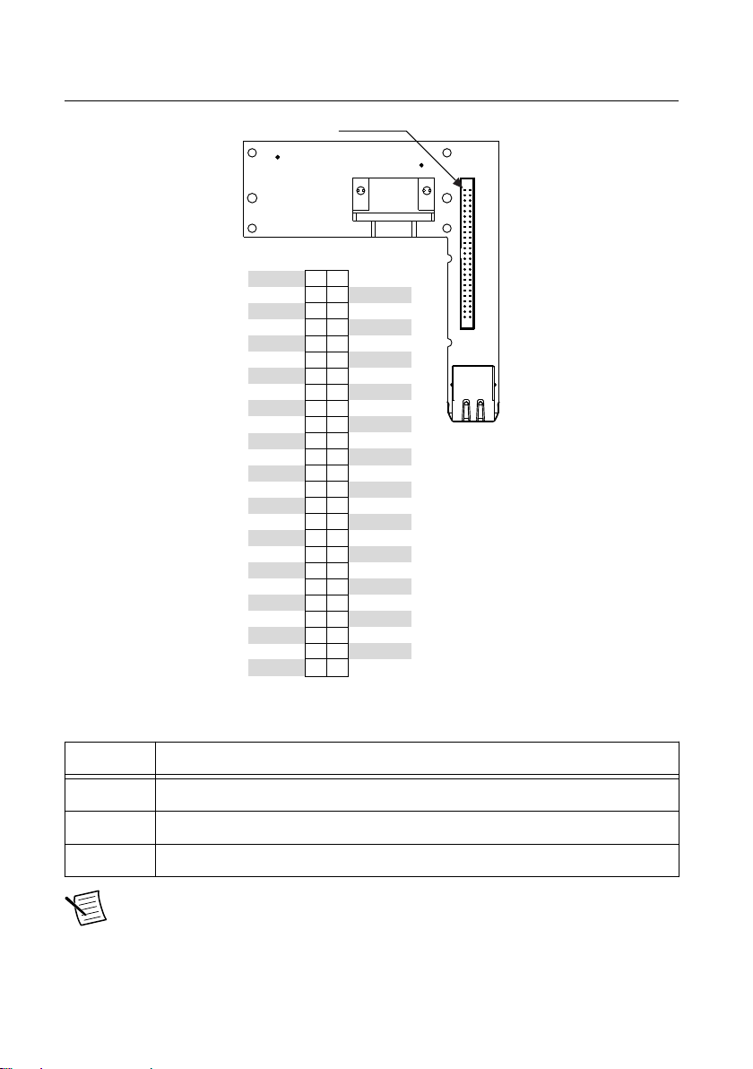
sbRIO-9698 Digital I/O Connector Pinout
J1, DIO
+5V
DGND
DGND
DGND
DGND
DGND
DGND
DGND
DGND
DGND
DGND
DGND
DGND
DGND
DGND
DGND
DGND
DGND
DGND
DGND
DGND
DGND
DGND
DGND
DGND
+5V
DIO22
DIO21
DIO19
DIO18
DIO17
DIO16
DIO23
DIO20
DIO15
DIO14
DIO13
DIO12
DIO11
DIO10
DIO9
DIO8
DIO7
DIO6
DIO5
DIO4
DIO3
DIO2
DIO1
DIO0
1 2
3 4
5 6
7 8
9
10
11 12
13 14
15 16
17 18
19 20
21 22
23 24
25 26
27 28
29 30
31 32
33 34
35 36
37 38
39 40
41 42
43 44
45 46
47 48
49 50
Pin 1
Signal Description
DGND Ground reference for the digital signal
DIO Digital input/output signal connection
+5 V 5 V power output connection for external devices
Note The DIO numbering on this connector corresponds to naming of the DIO on
the NI sbRIO device. For example, DIO0 on the sbRIO-9698 connector corresponds
to DIO0 on the NI sbRIO-9607/9627 RMC connector.
Table 1. Signal Descriptions
sbRIO-9698 User Manual and Specifications | © National Instruments | 3
Page 4
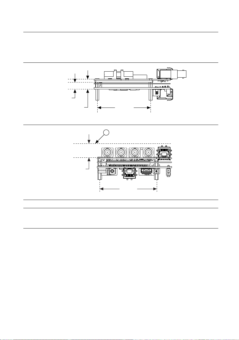
sbRIO-9698 Dimensions
71.7 mm
(2.82 in.)
13.4 mm
(0.53 in.)
9.2 mm
(0.36 in.)
1
18.0 mm
(0.71 in.)
73.6 mm
(2.90 in.)
The following figures show the side and rear dimensions of the sbRIO-9698. For twodimensional drawings and three-dimensional models of the sbRIO-9698, visit ni.com/
dimensions and search by model number.
Figure 3. Side View with Dimensions
Figure 4. Front View with Dimensions
1. Recommended Keepaway from Modules
Installing the sbRIO-9698
What to Use
• sbRIO-9698
• sbRIO device
• Socket driver, 4.5 mm
• Screwdriver, Phillips #1
4 | ni.com | sbRIO-9698 User Manual and Specifications
Page 5

What to Do
1. Attach the two C Series support brackets to the sbRIO-9698 using four of the M3 × 4 mm
black, low-profile screws included in the kit.
Note Do not tighten the screws until you reach step 8. You may need to adjust
the brackets during assembly.
Figure 5. Attaching the Support Brackets to the sbRIO-9698
2. Connect board-only C Series modules to the sbRIO-9698.
sbRIO-9698 User Manual and Specifications | © National Instruments | 5
Page 6

Caution To avoid causing damage to the sbRIO-9698 and the C Series
modules, do not allow C Series module support brackets to contact components
on the secondary side of the board-only C Series modules.
Figure 6. Connecting Board-only C Series Modules to the sbRIO-9698
3. Screw two of the remaining M3 × 4 mm black, low-profile screws into the holes.
Figure 7.
Inserting Two Screws into the Module and Bracket Holes
4. Insert the four M3 × 7 mm standoffs from the secondary side of the NI sbRIO device into
the four mounting standoffs for your application. The mounting standoffs are not included
in the sbRIO-9698 kit.
6 | ni.com | sbRIO-9698 User Manual and Specifications
Page 7

Figure 8. Inserting the Standoffs into the NI sbRIO Device
1
2
3
1. M3 × 7 mm Standoff (x4)
2. sbRIO Device
3. Mounting Standoff (x4, Not Provided)
5. Tighten the standoffs to 0.45 N · m (4.0 lb · in.). Do not overtighten.
6. Press the isolator sheet over the standoffs so that 1 mm to 2 mm of standoff protrudes
through the holes.
7. Align the bracket holes attached to the sbRIO-9698 with the tops of the M3 × 7 mm
standoffs, and insert the four M3 × 7 mm silver low-profile screws.
sbRIO-9698 User Manual and Specifications | © National Instruments | 7
Page 8

Figure 9. Inserting the Standoffs and Screws into the NI sbRIO Device
1
2
3
1. M3 × 7 mm Silver Low-Profile Screw (x4)
2. sbRIO-9698
3. Isolator
8. Tighten all the screws to 0.45 N · m (4.0 lb · in.). Do not overtighten.
sbRIO-9698 Specifications
Caution Do not operate the sbRIO-9698 in a manner not specified in this
document. Product misuse can result in a hazard. You can compromise the safety
protection built into the product if the product is damaged in any way. If the product
is damaged, return it to NI for repair.
8 | ni.com | sbRIO-9698 User Manual and Specifications
Page 9

Definitions
Warranted specifications describe the performance of a model under stated operating
conditions and are covered by the model warranty.
Characteristics describe values that are relevant to the use of the model under stated operating
conditions but are not covered by the model warranty.
• Typical specifications describe the performance met by a majority of models.
• Nominal specifications describe an attribute that is based on design, conformance testing,
or supplemental testing.
Specifications are Typical unless otherwise noted.
3.3 V Digital I/O on 50-Pin IDC Connector
Number of DIO channels 24
Maximum tested current per channel ±3 mA
Input logic levels
Input low voltage, V
Input high voltage, V
Output logic levels
Output high voltage, V
when sourcing 3 mA
Output low voltage, V
when sinking 3 mA
IL
IH
OH
OL
0 V minimum; 0.8 V maximum
2.0 V minimum; 5.25 V maximum
2.4 V minimum; 3.465 V maximum
0.0 V minimum; 0.4 V maximum
Network/Ethernet Port
Number of interfaces 1
Network interface 10Base-T, 100Base-TX, and
1000Base-T Ethernet
Compatibility IEEE 802.3
Communication rates 10 Mbps, 100 Mbps,
1000 Mbps auto-negotiated, half-/full-duplex
Maximum cabling distance 100 m/segment
Physical Characteristics
If you need to clean the device, wipe it with a dry towel.
Torque for screws 0.45 N · m (4.0 lb · in)
Weight 39 g (1.4 oz)
sbRIO-9698 User Manual and Specifications | © National Instruments | 9
Page 10

Environmental
Operating temperature
(IEC 60068-2-1, IEC 60068-2-2)
Thermal validation of an NI sbRIO system assembled with the sbRIO-9698 requires validating
the NI sbRIO device and board-only C Series modules. Measure the operating temperature of
board-only C Series modules 7.6 mm (0.3 in.) above the module surface. Refer to the
documentation of the NI sbRIO device and board-only C Series modules for operating
temperature limits and, if applicable, for typical specifications.
Storage temperature
(IEC 60068-2-1, IEC 60068-2-2)
Operating humidity
(IEC 60068-2-78, IEC 60068-2-2)
Storage humidity
(IEC 60068-2-78, IEC 60068-2-2)
Maximum altitude 5,000 m
Indoor use only.
-40 °C to 85 °C
-40 °C to 85 °C
10% RH to 90% RH, noncondensing
5% RH to 95% RH, noncondensing
Product Certifications and Declarations
Refer to the product Declaration of Conformity (DoC) for additional regulatory compliance
information. To obtain product certifications and the DoC for NI products, visit ni.com/
certification, search by model number or product line, and click the appropriate link in the
Certification column.
Environmental Management
NI is committed to designing and manufacturing products in an environmentally responsible
manner. NI recognizes that eliminating certain hazardous substances from our products is
beneficial to the environment and to NI customers.
For additional environmental information, refer to the Minimize Our Environmental Impact
web page at ni.com/environment. This page contains the environmental regulations and
directives with which NI complies, as well as other environmental information not included in
this document.
Waste Electrical and Electronic Equipment (WEEE)
EU Customers At the end of the product life cycle, all NI products must be
disposed of according to local laws and regulations. For more information about
how to recycle NI products in your region, visit ni.com/environment/weee.
10 | ni.com | sbRIO-9698 User Manual and Specifications
Page 11

电子信息产品污染控制管理办法(中国 RoHS)
中国客户 National Instruments 符合中国电子信息产品中限制使用某些有害物
质指令(RoHS)。关于 National Instruments 中国 RoHS 合规性信息,请登录
ni.com/environment/rohs_china。(For information about China RoHS
compliance, go to ni.com/environment/rohs_china.)
Worldwide Support and Services
The NI website is your complete resource for technical support. At ni.com/support, you have
access to everything from troubleshooting and application development self-help resources to
email and phone assistance from NI Application Engineers.
Visit ni.com/services for information about the services NI offers.
Visit ni.com/register to register your NI product. Product registration facilitates technical
support and ensures that you receive important information updates from NI.
NI corporate headquarters is located at 11500 North Mopac Expressway, Austin, Texas,
78759-3504. NI also has offices located around the world. For support in the United States,
create your service request at ni.com/support or dial 1 866 ASK MYNI (275 6964). For
support outside the United States, visit the Worldwide Offices section of ni.com/niglobal to
access the branch office websites, which provide up-to-date contact information.
sbRIO-9698 User Manual and Specifications | © National Instruments | 11
Page 12

Information is subject to change without notice. Refer to the NI Trademarks and Logo Guidelines at ni.com/trademarks for
information on NI trademarks. Other product and company names mentioned herein are trademarks or trade names of their
respective companies. For patents covering NI products/technology, refer to the appropriate location: Help»Patents in your
software, the patents.txt file on your media, or the National Instruments Patent Notice at ni.com/patents. You can find
information about end-user license agreements (EULAs) and third-party legal notices in the readme file for your NI product. Refer
to the Export Compliance Information at ni.com/legal/export-compliance for the NI global trade compliance policy and how
to obtain relevant HTS codes, ECCNs, and other import/export data. NI MAKES NO EXPRESS OR IMPLIED WARRANTIES AS
TO THE ACCURACY OF THE INFORMATION CONTAINED HEREIN AND SHALL NOT BE LIABLE FOR ANY ERRORS. U.S.
Government Customers: The data contained in this manual was developed at private expense and is subject to the applicable
limited rights and restricted data rights as set forth in FAR 52.227-14, DFAR 252.227-7014, and DFAR 252.227-7015.
© 2017 National Instruments. All rights reserved.
377267A-01 June 5, 2018
 Loading...