

Page 1
GETTING STARTED GUIDE
sbRIO-9687
General Purpose Inverter Controller Universal Interface Board
This document describes how to install and begin using the sbRIO-9687 GPIC Universal
Interface Board.
Contents
Safety Guidelines...................................................................................................................... 1
Unpacking the Kit..................................................................................................................... 2
Verifying the Kit Contents........................................................................................................ 2
Hardware Overview.................................................................................................................. 4
Dimensions................................................................................................................................4
Power........................................................................................................................................ 5
Preparing the Environment....................................................................................................... 6
Mounting the Hardware............................................................................................................ 6
Required Tools.................................................................................................................. 6
Installing the Thermal Kit and the sbRIO-9607................................................................7
Mounting the sbRIO-9683 or sbRIO-9684 ...................................................................... 8
Mounting the sbRIO-9687................................................................................................ 9
Surface Mounting Dimensions........................................................................................11
Connecting the sbRIO-9687....................................................................................................13
Connecting the Power..................................................................................................... 13
Powering on the sbRIO-9687..........................................................................................14
Connecting the sbRIO-9607 to the Host Computer........................................................ 14
Troubleshooting...................................................................................................................... 14
Where to Go Next................................................................................................................... 16
Related Documentation...........................................................................................................16
Worldwide Support and Services............................................................................................ 17
Safety Guidelines
Caution Do not operate the sbRIO-9687 in a manner not specified in this
document. Product misuse can result in a hazard. You can compromise the safety
protection built into the product if the product is damaged in any way. If the product
is damaged, return it to NI for repair.
Caution NI makes no product safety, electromagnetic compatibility (EMC), or CE
marking compliance claims for the sbRIO-9687. The end-product supplier is
responsible for conformity to any and all compliance requirements.
Page 2
Caution Exercise caution when placing the sbRIO-9687 inside an enclosure.
Auxiliary cooling may be necessary to keep the device under the maximum ambient
temperature rating for the sbRIO-9687. Refer to the sbRIO-9687 Specifications for
more information about the maximum ambient temperature rating.
Caution The sbRIO-9687 is designed for non-hazardous live signals. You must
ensure that all signals connected to the sbRIO-9687 are isolated from hazardous live
circuits and no unsafe voltages are present at the sbRIO-9687 inputs. Voltages that
exceed the specifications could result in damage to the sbRIO-9687.
Caution Use the sbRIO-9687 with only sbRIO-9683 or sbRIO-9684 devices. The
sbRIO-9687 is not electrically or mechanically compatible with other NI devices.
Caution The sbRIO-9683 or sbRIO-9684 simultaneous sampled isolated AI's
common ground is short circuited to the main ground on the sbRIO-9687 interface
board when assembled, defeating the channel-to-common isolation ratings of these
circuits.
Unpacking the Kit
Caution To prevent electrostatic discharge (ESD) from damaging the device,
ground yourself using a grounding strap or by holding a grounded object, such as
your computer chassis.
1. Touch the antistatic package to a metal part of the computer chassis.
2. Remove the device from the package and inspect the device for loose components or any
other sign of damage.
Caution Never touch the exposed pins of connectors.
Note Do not install a device if it appears damaged in any way.
3. Unpack any other items and documentation from the kit.
Store the device in the antistatic package when the device is not in use.
Verifying the Kit Contents
Verify the following components are in your kit.
• sbRIO-9687
• sbRIO power cable assembly, 9.5 in.
• (QTY 2) 10-pin flat data cable
• 2-pin power plug
• 2-pin plug for display power
2 | ni.com | sbRIO-9687 Getting Started Guide
Page 3

• 6-pin signal plug
• 12-pin signal plug
• (QTY 3) 24-pin signal plug
• (QTY 3) 26-pin signal plug
• (QTY 2) 36-pin signal plug
• Aluminum mounting plate
• (QTY 2) Handles
• (QTY 4) 8-32 × 3/8 in. panhead screws (for handles)
• (QTY 9) Standoffs and screws, I/F PCB to Panel, M3 × 43.36 mm M-F, 6 mm Hex,
M3 x 5 mm panhead screws
• (QTY 4) Standoffs and screws, RMC to I/F PCB, M3 x 11.12 mm M-F, 6 mm Hex,
M3 x 5 mm panhead screws
Also included is an OEM kit with an sbRIO-9607 CompactRIO Single-Board Controller, an
sbRIO-9683 or sbRIO-9684 General Purpose Inverter Controller (GPIC), and mounting
hardware:
• sbRIO-9607 controller
• sbRIO-9683 or sbRIO-9684 GPIC
• (QTY 4) Standoffs and screws, M3 × 43.36 mm M-F, 4.5 mm Hex, M3 × 5 mm panhead
screws
1
• (QTY 4) Standoffs, RMC to Panel, M3 × 29.81 mm M-F, 4.5 mm Hex (no screws)
• (QTY 4) Standoffs and screws, M3 × 11.12 mm M-F, 4.5 mm Hex, M3 × 5 mm panhead
screws
1
• (QTY 4) Standoffs and screws, sbRIO to RMC, M3 × 9.65 mm M-F, 4.5 mm Hex,
M3 × 5 mm panhead screws
• sbRIO power cable assembly, mini-fit pigtail, 2C, 12 in.
1
• NI 9683 User Manual and Specifications or NI 9684 User Manual and Specifications
• sbRIO Thermal Kit:
– Heat spreader
– Gap pad
– (QTY 4) Standoff, M3 × 16 mm, M-F, 4.5 Hex
– (QTY 2) Standoff, M3 × 18 mm, M-F, 4.5 Hex
1
– (QTY 6) M3 × 8 mm panhead screws
1
– Thermal Kit for NI sbRIO-9607/9627/9637 Installation and Specifications Manual
1
Some of the mounting hardware included with the OEM kits and the sbRIO Thermal Kit is not
required for this mounting procedure.
sbRIO-9687 Getting Started Guide | © National Instruments | 3
Page 4
Hardware Overview
The sbRIO-9687 is intended to be used together with the sbRIO-9683 or sbRIO-9684 General
Purpose Inverter Controller and the sbRIO-9607 CompactRIO Single-Board Controller. These
boards are designed to be stacked with board-to-board connectors.
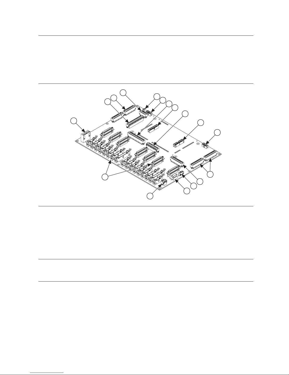
The following figure shows the components of the sbRIO-9687.
Figure 1. sbRIO-9687 Components
9
9
10
12
13
14
15
16
1
3
4
2
5
7
8
11
6
1. Power connector
2. Inverter connectors
3. Thermistor connector
4. Display RS232 connector
5. Display power connector
6. AO breakout connector
7. AI connectors
8. RS232 input
9. Expansion board connectors
10. HB signals breakout connector
11. DI breakout connector
12. CAN input
13. sbRIO-9607 power
14. Relay outputs
15. Feedback connectors
16. DO breakout connector
Dimensions
The following figures show the board dimensions and connector height for the sbRIO-9687.
For detailed dimensional drawings and 3D models, visit ni.com/dimensions and search for
9687.
4 | ni.com | sbRIO-9687 Getting Started Guide
Page 5
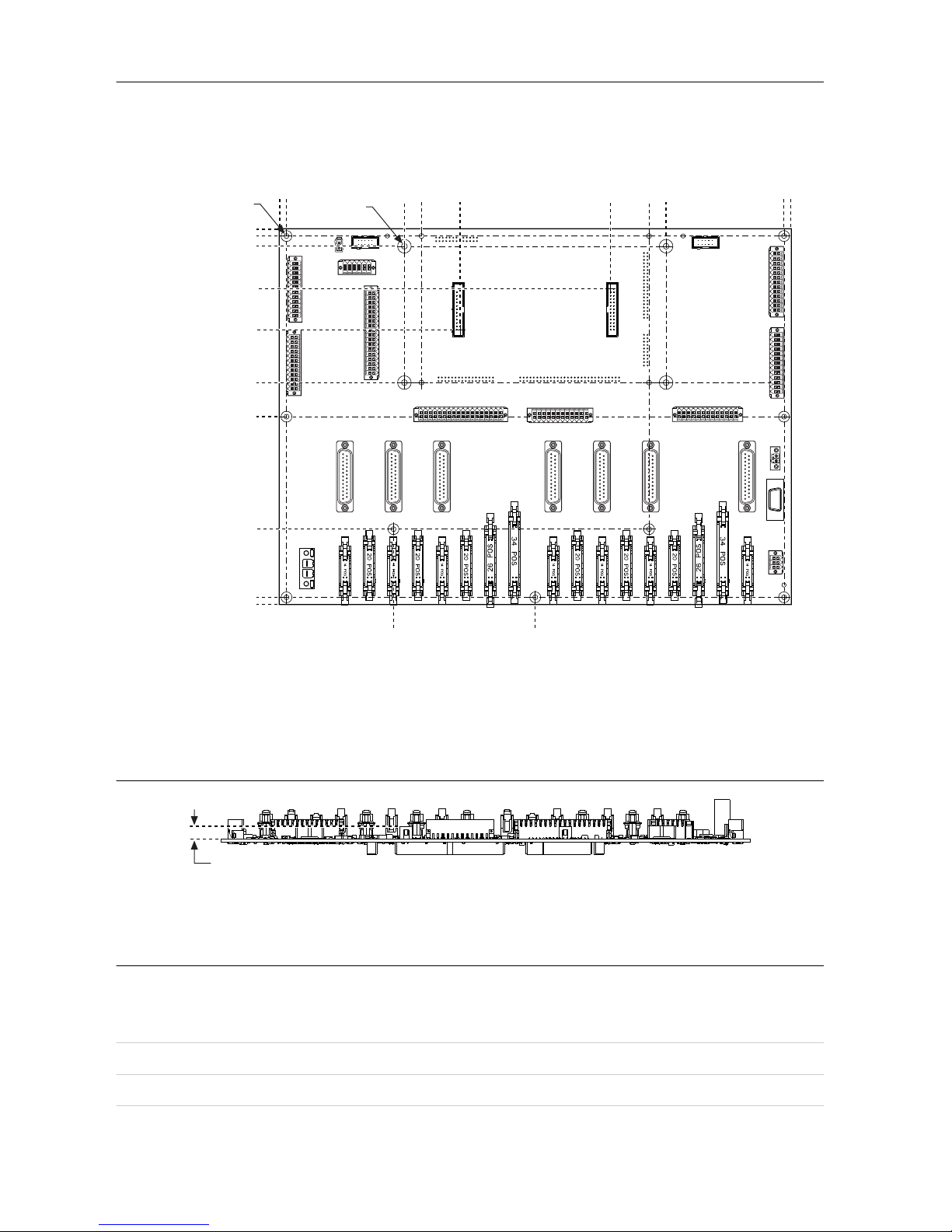
Figure 2. Primary Side Dimensions, Millimeters (Inches)
4X Ø 4.37 mm
(0.172 in.)
20.83 mm (0.820 in.)
84.84 mm (3.340 in.)
0.0 mm (0.00 in.)
13X Ø 3.68 mm (0.145 in.)
5.08 mm (0.200 in.)
7.62 mm (0.300 in.)
39.37 mm (1.550 in.)
69.85 mm (2.750 in.)
109.22 mm (4.300 in.)
134.62 mm (5.300 in.)
218.44 mm (8.600 in.)
269.24 mm (10.600 in.)
274.32 mm (10.800 in.)
105.66 mm (4.160 in.)
100.58 mm (3.960 in.)
12.7 mm (0.500 in.)
0.0 mm (0.00 in.)
28.85 mm (1.136 in.)
140.82 mm (5.544 in.)
169.67 mm (6.680 in.)
182.37 mm (7.180 in.)
270.26 mm (10.640 in.)
275.34 mm (10.840 in.)
Figure 3. Height of Expansion Board Connectors, Millimeters (Inches)
9.1 mm (0.358 in.)
Power
Input voltage (+24 V)
Typical +24 V
Maximum +28.8 V
Minimum +19.2 V
sbRIO-9687 Getting Started Guide | © National Instruments | 5
Page 6
Maximum DC input current 8 A
F4 Fuse 10 A, 250 VAC, Fast Acting, .25 in. × 1.25 in.
Onboard current consumption 0.1 A max
GPIC current consumption 0.75 A max
Preparing the Environment
Ensure that the environment in which you are using the sbRIO-9687 meets the following
specifications.
Operating temperature2 (IEC 60068-2-1,
IEC 60068-2-2)
-40 °C to 85 °C
Storage temperature (IEC 60068-2-1, IEC
60068-2-2)
-40 °C to 85 °C
Operating humidity (IEC 60068-2-78) 10% RH to 90% RH, noncondensing
Storage humidity (IEC 60068-2-78) 5% RH to 95% RH, noncondensing
Pollution degree 2
Maximum altitude 2,000 m
Indoor use only.
Note Refer to the device specifications on ni.com/manuals for complete
specifications.
Mounting the Hardware
Before you mount the sbRIO-9687, the thermal kit, sbRIO-9607 controller, and sbRIO-9683 or
sbRIO-9684 GPIC must be mounted to a thermally conductive surface at least 3 mm thick.
The thermally conductive surface acts as a heat spreader for the sbRIO-9607; ensure a good
thermal contact.
Required Tools
The following tools are required for mounting the sbRIO-9687:
• Screwdriver, Phillips #1
• Socket driver, 4.5 mm
2
Measure the local ambient temperature by placing thermocouples on both sides of the PCB, 5 mm
(0.2 in.) from the board surface. Users populating the sbRIO-9687 input termination resistors
should thermally validate that, in the vicinity of the resistors, the local ambient temperature does
not exceed 85 °C and the input termination resistor case temperatures and local PCB surface
temperatures do not exceed 125 °C.
6 | ni.com | sbRIO-9687 Getting Started Guide
Page 7

• Socket driver, 6 mm
• Thermal interface material
Note Eight M3 nuts are included with sbRIO-9684 mounting hardware. These M3
nuts are provided to secure the board assembly for temporary mounting
configurations where holes are not tapped into the mounting surface. To prevent
possible damage to the device, use caution when installing the M3 nuts.
Installing the Thermal Kit and the sbRIO-9607
Complete the following steps to install the sbRIO Thermal Kit and the sbRIO-9607.
1. Prepare the mounting surface by tapping holes according to the Surface Mounting
Dimensions.
2. Install the heat spreader to the mounting surface or use the aluminum plate to mount the
heat spreader.
a) Apply a thermal interface material, such as grease, to the flat side of the heat
spreader.
b) Align the heat spreader with the tapped holes for the sbRIO-9607. Refer to Figure 5,
Installing the sbRIO-9607, for orientation.
c) Fasten the four M3×16 mm, M-F standoffs through the heat spreader to the tapped
holes for the sbRIO-9607.
Tip Tighten all standoffs and screws to a maximum torque of 0.56 N · m
(5 lb · in.).
Figure 4. Mounting the Heat Spreader
3. Attach cables to the sbRIO-9607.
a) Attach a data cable to the sbRIO-9607 RS232 connector.
b) Attach a data cable to the sbRIO-9607 CAN connector.
c) Attach the power cable to the sbRIO-9607 power connector.
4. Apply the gap pad to the sbRIO-9607. Refer to the Thermal Kit for NI
sbRIO-9607/9627/9637 Installation and Specifications Manual for information about gap
pad placement.
5. Align the sbRIO-9607 with the heat spreader.
6. Fasten the four M3×9.65 mm, M-F standoffs through the sbRIO-9607 to the M3×16 mm,
M-F standoffs.
sbRIO-9687 Getting Started Guide | © National Instruments | 7
Page 8

Caution The gap pad is a viscoelastic material and compressing it too quickly
places a large amount of stress on board components. If you must use an
automatic screwdriver, fasten these screws at a rate less than 4.23 mm/s
(10 in./min.) to prevent damage during assembly.
Figure 5. Installing the sbRIO-9607
Mounting the sbRIO-9683 or sbRIO-9684
Once the sbRIO-9607 and Thermal Kit are installed, the next step is to install the sbRIO-9683
or sbRIO-9684 mezzanine board.
1. Install the M3 × 29.81 mm, M-F standoffs to the tapped holes for the sbRIO-9683 or
sbRIO-9684 .
2. Align the sbRIO-9683 or sbRIO-9684 with the M3 × 29.81 mm, M-F standoffs and the
sbRIO-9607.
3. Seat the mezzanine card connectors on the sbRIO-9683 or sbRIO-9684 and the
sbRIO-9607 to connect the boards.
4. Fasten the M3 × 11.12 mm, M-F, 6 mm Hex standoffs through the sbRIO-9683 or
sbRIO-9684 to the M3 × 29.81 mm, M-F standoffs.
5. Insert four M3 × 5 mm panhead screws through the sbRIO-9683 or sbRIO-9684 to the
M3 × 9.65 mm, M-F standoffs.
8 | ni.com | sbRIO-9687 Getting Started Guide
Page 9

Figure 6. Mating the sbRIO-9683 or sbRIO-9684 to the sbRIO-9607
Mounting the sbRIO-9687
1. Install the sbRIO-9687 handles.
a) Align the handles with the dedicated fixing holes on the sbRIO-9687.
b) Insert two 8-32 × 3/8 in. panhead screws for each handle through the sbRIO-9687.
2. Install the sbRIO-9687.
a) Install the M3 x 43.36, M-F 6 mm Hex standoffs (x9) in the tapped holes for the
sbRIO-9687.
sbRIO-9687 Getting Started Guide | © National Instruments | 9
Page 10

b) Align the sbRIO-9687 with the M3 x 43.36, M-F standoffs and the four M3 x 11.12,
M-F standoffs.
c) Seat the sbRIO-9687 connectors and the sbRIO-9683 or sbRIO-9684 connectors to
connect the boards.
d) Insert and tighten M3 x 5 panhead screws through the sbRIO-9687 to the installed
M3 x 43.36, M-F standoffs and to the M3 x 11.12, M-F standoffs.
e) Connect the CAN input cable and the RS232 input cable to sbRIO-9687 connectors
J1 and J2, respectively.
f) Connect the power cable between the sbRIO-9687 and the sbRIO-9607.
Figure 7. Mating the sbRIO-9687 to the sbRIO-9683 or sbRIO-9684
10 | ni.com | sbRIO-9687 Getting Started Guide
Page 11

The following figure shows the completed assembly of the sbRIO-9607 controller,
sbRIO-9683 or sbRIO-9684 mezzanine board, and the sbRIO-9687 GPIC universal
interface board.
Figure 8. Complete Assembly
Surface Mounting Dimensions
The following figures depict the mounting dimensions for the sbRIO-9687.
sbRIO-9687 Getting Started Guide | © National Instruments | 11
Page 12

Figure 9. Mounting Plate, Inches (Millimeters)
8.0 in
(203.2 mm)
11.0 in
(279.4 mm)
16.97 in
(430.91 mm)
16.47 in
(418.21 mm)
4X Ø .250 in
(6.35 mm)
.53 in
(13.34 mm)
12 | ni.com | sbRIO-9687 Getting Started Guide
Page 13

Figure 10. Standoffs, Inches (Millimeters)
3.34 in (84.84 mm)
0.0 in (0.0 mm)
0.85 in (21.6 mm)
3.67 in (93.33 mm)
4.3 in (109.22 mm)
5.3 in (134.62 mm)
8.6 in (218.44 mm)
10.6 in (269.24 mm)
Tap with M3 x 0.5 threads
5mm minimum thread depth
0.82 in (20.83 mm)
3.96 in (100.58 mm)
0.0 in (0.0 mm)
2.83 in (71.76 mm)
5.72 in (145.39 mm)
6.68 in (169.67 mm)
10.64 in (270.26 mm)
Connecting the sbRIO-9687
The top side of the PCB is the primary side of the sbRIO-9687 and contains connectors for
inverter modules, simultaneous AI, scanned AI and AO, feedback inputs, digital inputs, digital
outputs, relay outputs, display interface, expansion board, and power.
The bottom of the PCB, secondary side of the sbRIO-9687, contains the connectors for
interfacing with the sbRIO-9683 or sbRIO-9684 GPIC controller.
Connecting the Power
The sbRIO-9687 requires a 24 V DC power supply.
sbRIO-9687 Getting Started Guide | © National Instruments | 13
Page 14

The power supply should have a maximum output current higher than the current consumption
of the interface board and attached inverters. Refer to the sbRIO-9687 Specifications for the
sbRIO-9687 maximum current consumption.
Complete the following steps to connect a power supply to the device.
Caution Do not mate or unmate the power supply connectors while power is
applied.
1. Ensure that the power supply is powered off.
2. Insert the power connector plug into the power connector receptacle of the sbRIO device
until the connector latches into place.
3. Turn on the power supply.
Powering on the sbRIO-9687
The sbRIO-9687 turns ON immediately after the input power is present. One green LED is
always ON when power is present.
The sbRIO-9607 is powered through sbRIO-9687. The sbRIO-9607 runs a power-on self test
(POST) when it is powered on. During the POST, the Power and Status LEDs activate. The
Status LED turns off when the POST is complete. If the LEDs do not behave in this way when
the system powers on, refer to Troubleshooting.
Connecting the sbRIO-9607 to the Host Computer
Complete the following steps to connect the sbRIO-9607 to the host computer using the RJ-45
Ethernet port.
1. Power on the host computer.
2. Connect the sbRIO-9607 to the host computer using a standard Category 5 (CAT-5) or
better shielded, twisted-pair Ethernet cable.
Caution To prevent data loss and to maintain the integrity of your Ethernet
installation, do not use a cable longer than 100 m.
The first time you power up the device, it attempts to initiate a DHCP network connection. If
the device is unable to initiate a DHCP connection, it connects to the network with a link-local
IP address with the form 169.254.x.x. After the device has powered up, you must install
software on the device and configure the network settings in MAX.
Note Installing software may change the network behavior of the device. For
information about network behavior by installed software version, visit ni.com/info
and enter the code ipconfigcrio.
Troubleshooting
When the sbRIO-9687 is operating, the onboard power LED is ON. If the power LED is OFF,
check if the input power is present and has the correct polarity.
The following figure shows the LEDs on the sbRIO-9687.
14 | ni.com | sbRIO-9687 Getting Started Guide
Page 15

Figure 11. sbRIO-9687 LEDs
User LED
(Red)
User LED
(green)
User LED
(green)
Power LED
(always ON)
For details about troubleshooting the sbRIO-9607 or the sbRIO-9683 or sbRIO-9684 , consult
the related documentation.
If an issue persists after you complete a troubleshooting procedure, contact NI technical
support or visit ni.com/support.
sbRIO-9687 Getting Started Guide | © National Instruments | 15
Page 16

Where to Go Next
SUPPORT
Services
ni.com/services
NI Community
ni.com/community
NI Training
ni.com/training
Support
ni.com/support
SOFTWARE
CompactRIO Examples
NI Example Finder
Configuring a Project
NI Compact RIO Device Help
Learn LabVIEW Basics
ni.com/gettingstarted
NI Single-Board RIO CLIP
Generator Help–Reference
for the sbRIO CLIP Generator
application
ni.com/singleboard/setup
Tutorials, demos, and videos
for getting started with
NI sbRIO devices
HARDWARE
NI 9683 User Manual and
Specifications, NI 9684 User
Manual and Specifications
ni.com/manuals
NI sbRIO-9607/9627
RMC Design Guide
ni.com/manuals
sbRIO-9687 User Manual
ni.com/manuals
sbRIO-9687 Specifications
ni.com/manuals
Software Support
ni.com/info swsupport
Related Documentation
For additional information, refer to the following documents.
• sbRIO-9687 Specifications
• sbRIO-9687 User Manual
• NI sbRIO-9607 Getting Started Guide
• Thermal Kit for NI sbRIO-9607/9627/9637 Installation and Specifications Manual
• NI sbRIO-9607/9627 RIO Mezzanine Card Design Guide
• NI 9683 User Manual and Specifications
• NI 9684 User Manual and Specifications
Visit ni.com for the latest versions of these documents.
16 | ni.com | sbRIO-9687 Getting Started Guide
Page 17

Worldwide Support and Services
The NI website is your complete resource for technical support. At ni.com/support, you have
access to everything from troubleshooting and application development self-help resources to
email and phone assistance from NI Application Engineers.
Visit ni.com/services for information about the services NI offers.
Visit ni.com/register to register your NI product. Product registration facilitates technical
support and ensures that you receive important information updates from NI.
A Declaration of Conformity (DoC) is our claim of compliance with the Council of the
European Communities using the manufacturer’s declaration of conformity. This system
affords the user protection for electromagnetic compatibility (EMC) and product safety. You
can obtain the DoC for your product by visiting ni.com/certification. If your product supports
calibration, you can obtain the calibration certificate for your product at ni.com/calibration.
NI corporate headquarters is located at 11500 North Mopac Expressway, Austin, Texas,
78759-3504. NI also has offices located around the world. For support in the United States,
create your service request at ni.com/support or dial 1 866 ASK MYNI (275 6964). For
support outside the United States, visit the Worldwide Offices section of ni.com/niglobal to
access the branch office websites, which provide up-to-date contact information.
sbRIO-9687 Getting Started Guide | © National Instruments | 17
Page 18

Information is subject to change without notice. Refer to the NI Trademarks and Logo Guidelines at ni.com/trademarks for
information on NI trademarks. Other product and company names mentioned herein are trademarks or trade names of their
respective companies. For patents covering NI products/technology, refer to the appropriate location: Help»Patents in your
software, the patents.txt file on your media, or the National Instruments Patent Notice at ni.com/patents. You can find
information about end-user license agreements (EULAs) and third-party legal notices in the readme file for your NI product. Refer
to the Export Compliance Information at ni.com/legal/export-compliance for the NI global trade compliance policy and how
to obtain relevant HTS codes, ECCNs, and other import/export data. NI MAKES NO EXPRESS OR IMPLIED WARRANTIES AS
TO THE ACCURACY OF THE INFORMATION CONTAINED HEREIN AND SHALL NOT BE LIABLE FOR ANY ERRORS. U.S.
Government Customers: The data contained in this manual was developed at private expense and is subject to the applicable
limited rights and restricted data rights as set forth in FAR 52.227-14, DFAR 252.227-7014, and DFAR 252.227-7015.
© 2017 National Instruments. All rights reserved.
377230A-01 December 18, 2017
 Loading...