

Page 1
GETTING STARTED GUIDE
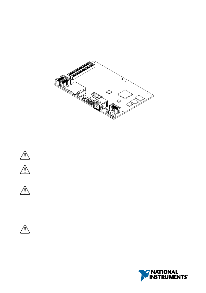
NI sbRIO-9637
Single-Board RIO OEM Devices
This document describes how to begin using the NI sbRIO-9637.
Safety Guidelines
Operate the sbRIO-9637 only as described in the user documentation.
Caution The sbRIO-9637 must be installed in a suitable enclosure prior to use.
Caution NI makes no product safety, electromagnetic compatibility (EMC), or CE
marking compliance claims for the sbRIO-9637. The end-product supplier is
responsible for conformity to any and all compliance requirements.
Caution Exercise caution when designing an enclosure for the sbRIO-9637.
Auxiliary cooling may be necessary to keep the sbRIO-9637 within the specified
operating temperature range. Refer to the NI sbRIO-9637 Specifications on ni.com/
manuals for more information about the maximum operating temperature rating. For
information and examples regarding factors that can affect thermal performance,
visit ni.com/info and enter the Info Code sbriocooling.
Caution Do not operate the sbRIO-9637 in a manner not specified in this
document. Product misuse can result in a hazard. You can compromise the safety
protection built into the product if the product is damaged in any way. If the product
is damaged, return it to NI for repair.
Page 2
Safety Voltages
Connect only voltages that are below these limits.
V terminal to C terminal 30 VDC maximum, Measurement Category I
Measurement Category I is for measurements performed on circuits not directly connected to
the electrical distribution system referred to as MAINS voltage. MAINS is a hazardous live
electrical supply system that powers equipment. This category is for measurements of voltages
from specially protected secondary circuits. Such voltage measurements include signal levels,
special equipment, limited-energy parts of equipment, circuits powered by regulated lowvoltage sources, and electronics.
Caution Do not connect the sbRIO-9637 to signals or use for measurements within
Measurement Categories II, III, or IV.
Preparing the Environment
Ensure that the environment in which you are using the sbRIO-9637 meets the following
specifications.
Local ambient operating temperature near
device (IEC 60068-2-1, IEC 60068-2-2)
Maximum reported onboard sensor temperature
CPU/FPGA temperature 98 °C
Primary System temperature 85 °C
Secondary System temperature 85 °C
Note Ensure that the local ambient, reported CPU/FPGA, and reported Primary
System temperatures do not exceed any of the maximum temperatures listed in this
document. For more information about how to access the onboard sensors, visit
ni.com/info and enter the Info Code sbriosensors.
Operating humidity (IEC 60068-2-78) 10% RH to 90% RH, noncondensing
Pollution Degree (IEC 60664) 2
Maximum altitude 5,000 m
Indoor use only.
Note Refer to the device specifications on ni.com/manuals for complete
specifications.
-40 °C to 85 °C
2 | ni.com | NI sbRIO-9637 Getting Started Guide
Page 3
Unpacking the Kit
1
2 3
4
5 6 7
8
Caution To prevent electrostatic discharge (ESD) from damaging the device,
ground yourself using a grounding strap or by holding a grounded object, such as
your computer chassis.
1. Touch the antistatic package to a metal part of the computer chassis.
2. Remove the device from the package and inspect the device for loose components or any
other sign of damage.
Caution Never touch the exposed pins of connectors.
Note Do not install a device if it appears damaged in any way.
3. Unpack any other items and documentation from the kit.
Store the device in the antistatic package when the device is not in use.
Verifying the Kit Contents
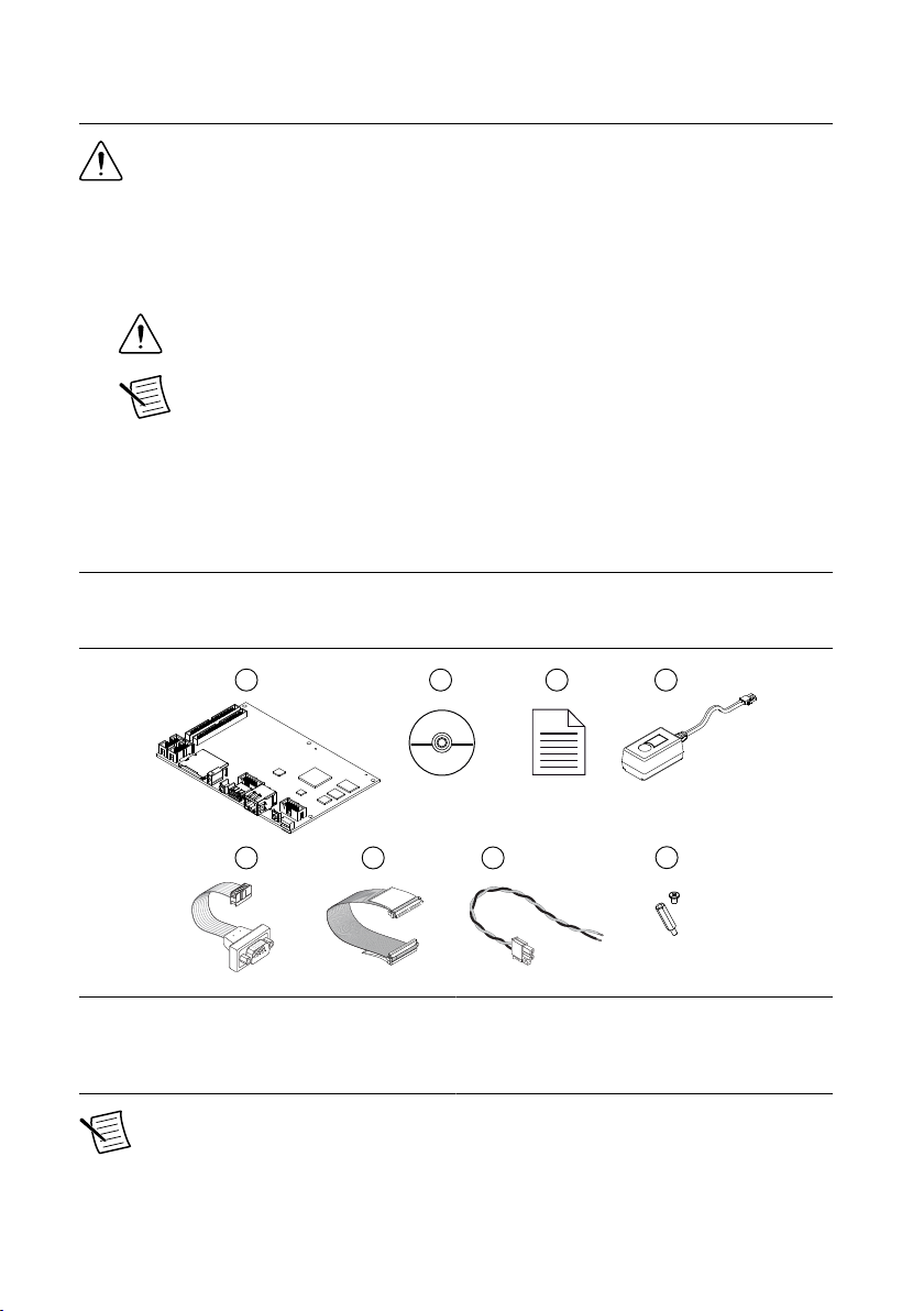
Verify that the following items are included in the sbRIO-9637 kit.
Figure 1. sbRIO-9637 Kit Contents
1. sbRIO Device
2. NI CompactRIO Device Drivers Media
3. Getting Started Guide
4. Power Supply
Note The provided power supply is only intended for the getting started
experience. NI recommends the use of a power supply that meets the specifications
listed in the NI sbRIO-9637 Specifications for system deployment.
5. 10-pin IDC to 9-pin DSUB Cable
6. 50-pin IDC Ribbon Cable
7. Power Cable Assembly
8. Standoffs and Screws
NI sbRIO-9637 Getting Started Guide | © National Instruments | 3
Page 4
Installing Software on the Host Computer
1
17
16
20
19
18
15
13
12
2
3
4 5
6
7
8
9
10
11
14
14
Before using the sbRIO-9637, you must install the following application software and device
drivers on the host computer.
1. LabVIEW 2015 or later
2. LabVIEW Real-Time Module 2015 or later
3. LabVIEW FPGA Module 2015 or later
4. NI CompactRIO Device Drivers August 2015 or later
For minimum software support information, visit ni.com/info and enter the Info Code
softwareversion.
Connecting the sbRIO-9637
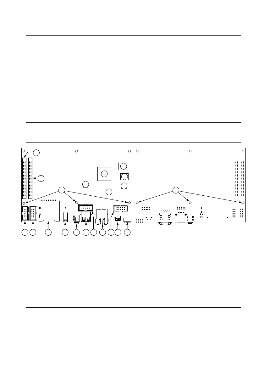
The sbRIO-9637 has the following components.
Figure 2. sbRIO-9637 Components
1. W3, RS-485 (COM3)
2. W4, RS-232 (COM2)
3. J6, SDHC
4. J9, Power Connector
5. Chassis Ground Bracket
6. J10, USB Host Port
7. W1, CAN (CAN0)
8. J7, RJ-45 Ethernet Port
9. W2, RS-232 (COM1)
10. Reset Switch
4 | ni.com | NI sbRIO-9637 Getting Started Guide
11. LEDs
12. J4, DIO
13. J5, MIO
14. Mounting Holes Connected to Chassis Ground
15. Ethernet RGMII Transceiver
16. ULPI USB Transceiver
17. FPGA Processor
18. DDR Memory
19. NAND Flash
20. CPLD
Page 5

Connecting the sbRIO-9637 to Power
The NI sbRIO device requires a 9 VDC to 30 VDC external power supply. The NI sbRIO
device filters and regulates the supplied power and provides power for RMCs.
Note Refer to the Power Requirements section of the NI sbRIO-9637
Specifications for the complete power requirement specifications.
Note Refer to the Power Requirements section of the NI sbRIO-9637 User Manual
for formulas and examples for calculating power requirements for different
configurations and application types.
Note Refer to the Power Requirements section of the NI sbRIO-9637 User Manual
for proper wiring of the power cable assembly.
Complete the following steps to connect a power supply to the device.
Caution Do not mate or unmate the power supply connectors while power is
applied.
1. Ensure that your power supply is powered off.
2. Insert the power connector plug into the power connector receptacle of the NI sbRIO
device until the connector latches into place.
3. Turn on the power supply.
Powering On the NI sbRIO Device
The NI sbRIO device runs a power-on self test (POST) when you apply power to the device.
During the POST, the Power and Status LEDs turn on. When the Status LED turns off, the
POST is complete. If the LEDs do not behave in this way when the system powers on, refer to
the STATUS LED Indicators section.
Connecting the sbRIO-9637 to the Host Computer
Complete the following steps to connect the sbRIO-9637 to the host computer using the RJ-45
Ethernet port.
1. Power on the host computer.
2. Connect the sbRIO-9637 to the host computer using a standard Category 5 (CAT-5) or
better shielded, twisted-pair Ethernet cable.
Caution To prevent data loss and to maintain the integrity of your Ethernet
installation, do not use a cable longer than 100 m.
The first time you power up the device, it attempts to initiate a DHCP network
connection. If the device is unable to initiate a DHCP connection, it connects to the
network with a link-local IP address with the form 169.254.x.x. After the device has
NI sbRIO-9637 Getting Started Guide | © National Instruments | 5
Page 6

powered up, you must install software on the device and configure the network settings in
MAX.
Note Installing software may change the network behavior of the device. For
information about network behavior by installed software version, visit ni.com/
info and enter the Info Code ipconfigcrio.
Configuring the System in Measurement & Automation Explorer (MAX)
Complete the following steps to find the system in MAX.
1. Launch MAX on the host computer.
2. Expand Remote Systems in the configuration tree and locate your system.
3. Select your target.
Tip MAX lists the system under the model number followed by the serial
number, such as NI-sbRIO-9637-########.
Setting a System Password
Complete the following steps to set a system password.
Note The default username for the sbRIO-9637 is admin. There is no default
password for the sbRIO-9637, so you must leave the password field blank when
logging in until you set a system password.
1. Right-click your system and select
The NI Web-Based Configuration and Monitoring utility opens in your default browser
and is where you set the password. If you have not installed Microsoft Silverlight,
NI Web-based Configuration & Monitoring prompts you to do so.
2. Enter a unique name for your system in the Hostname field.
3. Click the Security Configuration icon.
4. Click Login.
5. In the Login dialog box, enter the username admin and leave the password field blank.
6. Click OK.
7. Click Change Password.
8. Enter and re-enter a new password.
9. Click OK.
10. Click Save.
11. Click OK to confirm you are changing the password.
Web Configuration.
Caution NI cannot recover lost system passwords. If you forget the password,
you must contact NI and reformat the controller.
6 | ni.com | NI sbRIO-9637 Getting Started Guide
Page 7

Installing Software on the sbRIO-9637
Complete the following steps to install software on the sbRIO-9637.
1. In MAX, expand your system under Remote Systems.
2. Right-click Software.
3. Select Add/Remove Software to launch the LabVIEW Real-Time Software Wizard.
Tip You must log in if you set a system password.
4. Select the recommended software set for your LabVIEW and NI CompactRIO Device
Drivers versions.
5. Click Next.
6. Select NI Scan Engine from the software add-ons.
Select any additional software to install. If you plan on using the sbRIO-9637 with the
LabVIEW FPGA Module, you can click Next.
Tip You can use this wizard at anytime to install additional software.
7. Click Next.
8. Verify that the summary of software to install is correct.
9. Click Next to start the installation.
10. Click Finish when the installation is complete.
Troubleshooting the sbRIO-9637
The sbRIO-9637 is Not Communicating with the Network
• Ensure that the Ethernet connections between the sbRIO-9637 and the host computer and
the Ethernet connections between the host computer and the router are secure.
• Ensure that you have the correct version of NI CompactRIO Device Drivers installed on
the host computer. Visit ni.com/info and enter the Info Code softwareversion for the
minimum supported versions of LabVIEW and NI CompactRIO Device Drivers.
Tip If you have recently upgraded LabVIEW, you must reinstall NI
CompactRIO Device Drivers.
• Temporarily disable any network firewalls or other security software.
Configure the IP and other network settings by completing the following steps.
1. Use a standard Category 5 (CAT-5) or better shielded, twisted-pair Ethernet cable to
connect the sbRIO-9637 Ethernet port to a host computer. The sbRIO-9637 attempts to
initiate a DHCP network connection at powerup.
NI sbRIO-9637 Getting Started Guide | © National Instruments | 7
Page 8

2. In MAX, expand your system under Remote Systems and select Troubleshoot Remote
Press and hold RESET button for ≥ 5 s
Press and hold RESET button for < 5 s
Run Mode
Safe Mode
Press and hold RESET button for < 5 s
Press and hold RESET button for ≥ 5 s
Press and hold
RESET button for ≥ 5 s
Press and hold
RESET button for < 5 s
• Console Out enabled
• Network settings reset
• RT Startup App disabled
• FPGA Startup App disabled
• Console Out enabled
• RT Startup App disabled
• FPGA Startup App disabled
Safe Mode
System Discovery.
System Reset
The following figure shows the reset behavior of the sbRIO-9637.
Figure 3. Reset Button Behavior
STATUS LED Indicators
The following table lists the STATUS LED indicators.
8 | ni.com | NI sbRIO-9637 Getting Started Guide
Page 9

Table 1. STATUS LED Indicators
LED Pattern Indication
Blinks twice and
pauses
The sbRIO-9637 is in safe mode. Software is not installed, which is the
factory default state, or software has been improperly installed on the
sbRIO-9637.
An error can occur when an attempt to upgrade the software is
interrupted. Reinstall software on the sbRIO-9637. Refer to the
Measurement & Automation Explorer (MAX) Help for information
about installing software on the sbRIO-9637.
Blinks three times
and pauses
The sbRIO-9637 is in user-directed safe mode, or the sbRIO-9637 is in
install mode to indicate that software is currently being installed.
This pattern may also indicate that the user has forced the sbRIO-9637
to boot into safe mode by pressing the reset button for longer than five
seconds or by enabling safe mode in MAX. Refer to the Measurement
& Automation Explorer (MAX) Help for information about safe mode.
Blinks four times
and pauses
The sbRIO-9637 is in safe mode. The software has crashed twice
without rebooting or cycling power between crashes.
This usually indicates that the sbRIO-9637 has run out of memory.
Review your LabVIEW Real-Time application to resolve any memory
leaks.
Continuously blinks The sbRIO-9637 has not booted into NI Linux Real-Time. The
sbRIO-9637 either booted into an unsupported operating system, was
interrupted during the boot process, or detected an unrecoverable
software error.
On momentarily The sbRIO-9637 is booting. No action required.
Off The sbRIO-9637 is in run mode. Software is installed and the
operating system is running.
NI sbRIO-9637 Getting Started Guide | © National Instruments | 9
Page 10

Where to Go Next
SUPPORT
Services
ni.com/services
NI Community
ni.com/community
NI Training
ni.com/training
Support
ni.com/support
SOFTWARE
CompactRIO Examples
NI Example Finder
Configuring a Project
NI Compact RIO Device Help
Learn LabVIEW Basics
ni.com/gettingstarted
NI Single-Board RIO CLIP
Generator Help–Reference
for the sbRIO CLIP Generator
application
ni.com/singleboard/setup
Tutor ials, demos, and videos
for getting started with
NI sbRIO devices
HARDWARE
NI sbRIO-9637 User Manual
ni.com/manuals
NI sbRIO-9637 Specifications
ni.com/manuals
Software Support
ni.com/info swsupport
Worldwide Support and Services
The National Instruments website is your complete resource for technical support. At ni.com/
support, you have access to everything from troubleshooting and application development
self-help resources to email and phone assistance from NI Application Engineers.
Visit ni.com/services for NI Factory Installation Services, repairs, extended warranty, and
other services.
Visit ni.com/register to register your National Instruments product. Product registration
facilitates technical support and ensures that you receive important information updates from
NI.
National Instruments corporate headquarters is located at 11500 North Mopac Expressway,
Austin, Texas, 78759-3504. National Instruments also has offices located around the world.
For telephone support in the United States, create your service request at ni.com/support or
10 | ni.com | NI sbRIO-9637 Getting Started Guide
Page 11

dial 1 866 ASK MYNI (275 6964). For telephone support outside the United States, visit the
Worldwide Offices section of ni.com/niglobal to access the branch office websites, which
provide up-to-date contact information, support phone numbers, email addresses, and current
events.
NI sbRIO-9637 Getting Started Guide | © National Instruments | 11
Page 12

Refer to the NI Trademarks and Logo Guidelines at ni.com/trademarks for information on National Instruments trademarks.
Other product and company names mentioned herein are trademarks or trade names of their respective companies. For patents
covering National Instruments products/technology, refer to the appropriate location: Help»Patents in your software, the
patents.txt file on your media, or the National Instruments Patent Notice at ni.com/patents. You can find information about
end-user license agreements (EULAs) and third-party legal notices in the readme file for your NI product. Refer to the Export
Compliance Information at ni.com/legal/export-compliance for the National Instruments global trade compliance policy and
how to obtain relevant HTS codes, ECCNs, and other import/export data. NI MAKES NO EXPRESS OR IMPLIED WARRANTIES
AS TO THE ACCURACY OF THE INFORMATION CONTAINED HEREIN AND SHALL NOT BE LIABLE FOR ANY ERRORS.
U.S. Government Customers: The data contained in this manual was developed at private expense and is subject to the
applicable limited rights and restricted data rights as set forth in FAR 52.227-14, DFAR 252.227-7014, and DFAR 252.227-7015.
© 2014—2015 National Instruments. All rights reserved.
376416A-01 Aug15
 Loading...