

Page 1

RT Series
DAQ Device User Manual
RT Series DAQ Device User Manual
April 2000 Edition
Part Number 322635A-01
Page 2

Worldwide Technical Support and Product Information
www.ni.com
National Instruments Corporate Headquarters
11500 North Mopac Expressway Austin, Texas 78759-3504 USA Tel: 512 794 0100
Worldwide Offices
Australia 03 9879 5166, Austria 0662 45 79 90 0, Belgium 02 757 00 20, Brazil 011 284 5011,
Canada (Calgary) 403 274 9391, Canada (Ontario) 905 785 0085, Canada (Québec) 514 694 8521,
China 0755 3904939, Denmark 45 76 26 00, Finland 09 725 725 11, France 01 48 14 24 24,
Germany 089 741 31 30, Greece 30 1 42 96 427, Hong Kong 2645 3186, India 91805275406,
Israel 03 6120092, Italy 02 413091, Japan 03 5472 2970, Korea 02 596 7456, Mexico (D.F.) 5 280 7625,
Mexico (Monterrey) 8 357 7695, Netherlands 0348 433466, New Zealand 09 914 0488, Norway 32 27 73 00,
Poland 0 22 528 94 06, Portugal 351 1 726 9011, Singapore 2265886, Spain 91 640 0085,
Sweden 08 587 895 00, Switzerland 056 200 51 51, Taiwan 02 2528 7227, United Kingdom 01635 523545
For further support information, see the Technical Support Resources appendix. To comment on the
documentation, send e-mail to techpubs@ni.com
© Copyright 1999, 2000 National Instruments Corporation. All rights reserved.
Page 3

Important Information
Warranty
The RT Series DAQ hardware is warranted against defects in materials and workmanship for a period of one year from the date
of shipment, as evidenced by receipts or other documentation. National Instruments will, at its option, repair or replace equip ment
that proves to be defective during the warranty period. Th is warrant y in cludes parts and labor.
The media on which you receive National Instruments software are warranted not to fail to execute programming instructions,
due to defects in materials and workmanship, for a period of 90 days from date of sh ipmen t, as evid enced b y receipt s o r other
documentation. National Instruments will, at its op ti on , repair or repl ace soft ware me dia th at do not ex ecu te pr ogram mi ng
instructions if National Instruments receives notice of such defects during the warranty period. National Instruments does not
warrant that the operation of the software shall be uni nterrup ted or error free.
A Return Material Authorization (RMA) number must be obtained from the factory and clearly marked on the outside of
the package before any equipment will be accepted for warranty work. National Instruments will pay the shipping costs of
returning to the owner parts which are covered by warrant y.
National Instruments believes that the information in this document is accurate. The document has been carefully reviewed
for technical accuracy. In the event that technical or typographical errors exist, National Instruments reserves the right to
make changes to subsequent editions of this document withou t p rio r no ti ce to hold ers o f thi s ed itio n. The read er sh ou ld consul t
National Instruments if errors are suspected. In no even t shall Nati on al Inst rum ents be l iable fo r any dama ges aris in g o ut of
or related to this document or the information contained in it.
XCEPT AS SPECIFIED HEREIN
E
WARRANTY OF MERCHANTABILITY OR FITNESS FOR A PARTICULAR PURPOSE
NEGLIGENCE ON THE PART OF NATIONAL INSTRUMENTS SHALL BE LIMITED TO THE AMOUNT THERETOFORE PAID BY THE CUSTOMER
NSTRUMENTS WILL NOT BE LIABLE FOR DAMAGES RESULTING FROM LOSS OF DATA, PROFITS, USE OF PRODUCTS, OR INCIDENTAL OR
I
CONSEQUENTIAL DAMAGES, EVEN IF ADVISED OF THE POSSIBILITY THEREOF
apply regardless of the form of action, whether in contract or tort, including negligence. Any action against National Instruments
must be brought within one year after the cause of action accrues. National Instruments shall not be liable for any delay in
performance due to causes beyond its reasonable control. The warranty provided herein does not co ver d amag es, defects,
malfunctions, or service failures caused by ow ner’s fai lu re t o foll ow th e Nation al Inst rum ent s in stal l ation, op erat i on, or
maintenance instructions; owner’s modification of the pro du ct; ow ner’s abus e, m isus e, or negligent acts; and po wer failure or
surges, fire, flood, accident, actions of third parties, or other events outside reasonable control.
ATIONAL INSTRUMENTS MAKES NO WARRANTIES, EXPRESS OR IMPLIED, AND SPECIFICALLY DISCLAIMS ANY
, N
Copyright
Under the copyright laws, this publication may not be reproduced or transmitted in any form, electronic or mechanical, including
photocopying, recording, storing in an informatio n retriev al s ystem, o r t ran sl ating , in who le or i n p art, wit ho ut t he prior written
consent of National Instruments Corporation.
USTOMER’S RIGHT TO RECOVER DAMAGES CAUSED BY FAULT OR
. C
. This limitation of the liability of National Instruments will
. N
ATIONAL
Trademarks
LabVIEW™, MITE™, National Instruments™, ni.com™, NI-DAQ™, PXI™, RTSI™, and SCXI™ are trademarks of
National Instruments Corporati on.
Product and company names mentioned herein are trad emarks o r trad e name s of thei r respect ive compan ies .
WARNING REGARDING USE OF NATIONAL INSTRUMENTS PRODUCTS
(1) NATIONAL INSTRUMENTS PRODUCTS ARE NOT DESIGNED WITH COMPONENTS AND TESTING FOR A LEVEL
OF RELIABILITY SUITABLE FOR USE IN OR IN CONNECTION WITH SURGICAL IMPLANTS OR AS CRITICAL
COMPONENTS IN ANY LIFE SUPPORT SYSTEMS WHOSE FAILURE TO PERFORM CAN REASONABLY BE
EXPECTED TO CAUSE SIGNIFICANT INJURY TO A HUMAN.
(2) IN ANY APPLICATION, I NCLUDING THE ABOVE , RELIABILITY OF OP ERATION OF THE SOFT WARE PRODUCTS
CAN BE IMPAIRED BY ADVERSE FACTORS, INCLUDING BUT NOT LIMITED TO FLUCTUATIONS IN ELECTRICAL
POWER SUPPLY, COMPUTER HARDWARE MALFUNCTIONS, COMPUTER OPERATING SYSTEM SOFTWARE
FITNESS, FITNESS OF COMPILERS AND DEVELOPMENT SOFTWARE USED TO DE VEL OP AN APPLICAT ION,
INSTALLATION ERRORS, SOFTWARE AND HARDWARE COMPATIBILITY PROBLEMS, MALFUNCTIONS OR
FAILURES OF ELECTRONIC MONITORING OR CONTROL DEVICES, TRANSIENT FAILURES OF ELECTRONIC
SYSTEMS (HARDWARE AND/OR SOFTWARE), UNANTICIPATED USES OR MISUSES, OR ERRORS ON THE PART OF
THE USER OR APPLICATIONS DESIGNER (ADVERSE FACTORS SUCH AS THESE ARE HEREAFTER
COLLECTIVELY TERMED “SYSTEM FAILURES”). ANY APPLICATION WHERE A SYSTEM FAILURE WOULD
CREATE A RISK OF HARM TO PROPERTY OR PERSONS (INCLUDING THE RISK OF BODILY INJURY AND DEATH)
SHOULD NOT BE RELIANT SOLELY UPON ONE FORM OF ELECTRON IC SYSTE M DUE TO THE RISK OF SYSTEM
FAILURE. TO AVOID DAMAGE, INJURY, OR DEATH, THE USER OR APPLICATION DESIGNE R MU ST T AKE
REASONABLY PRUDENT STEPS TO PROTECT AGAINST SYSTEM FAILURES, INCLUDING BUT NOT LIMITED TO
BACK-UP OR SHUT DOWN MECHANISMS. BECAUSE EACH END-USER SYSTEM IS CUSTOMIZED AND DIFFERS
FROM NATIONAL INSTRUMENTS' TESTING PLATFORMS AND BECAUSE A USER OR APPLICATION DESIGNER
MAY USE NATIONAL INSTRUMENTS PRODUCTS IN COMBINATION WITH OTHER PRODUCTS IN A MANNER NOT
EVALUATED OR CONTEMPLATED BY NATIONAL INSTRUMENTS, THE USER OR A PPLICATION DE SIGNER IS
ULTIMATELY RESPONSIBLE FOR VERIFYING AND VALIDATING THE SUITAB ILITY OF NA TIONAL
INSTRUMENTS PRODUCTS WHENEVER NATIONAL INSTRUMENTS PRODUCTS ARE INCORPORATED IN A
SYSTEM OR APPLICATION, INCLUDING, WITHOUT LIMITATION, THE APPROPRIATE DESIGN, PROCESS AND
SAFETY LEVEL OF SUCH SYSTEM OR APPLICATION.
Page 4
Compliance
FCC/Canada Radio Frequency Interference Compliance*
Determining FCC Class
The Federal Communications Commission (FCC) has rules to protect wireless communications from interference.
The FCC places digital electronics into two classes. These classes are known as Class A (for use in industrialcommercial locations only) or Class B (for use in residential or commercial locations). Depending on where it is
operated, this product could be subject to restrictions in the FCC rules. (In Canada, the Department of
Communications (DOC), of Industry Canada, regulates wireless interference in much the same way.)
Digital electronics emit weak signals during normal operation that can affect radio, television, or other wireless
products. By examining the product you purchased, you can determine the FCC Class and therefore which of the two
FCC/DOC Warnings apply in the following sections. (Some products may not be labelled at all for FCC, if so the
reader should then assume these are Class A devices.)
FCC Class A products only display a simple warning statement of one paragraph in length regarding interference and
undesired operation. Most of our products are FCC Class A. The FCC rules have restrictions regarding the locations
where FCC Class A products can be operated.
FCC Class B products display either a FCC ID code, starting with the letters EXN,
or the FCC Class B compliance mark that appears as shown here on the right.
The curious reader can consult the FCC web site
information.
FCC/DOC Warnings
This equipment generates and uses radio frequency energy and, if not installed and used in strict accordance with the
instructions in this manual and the CE Mark Declaration of Conformity**, may cause interference to radio and
television reception. Classification requirements are the same for the Federal Communications Commission (FCC)
and the Canadian Department of Communications (DOC).
Changes or modifications not expressly approved by National Instruments could void the user’s authority to operate
the equipment under the FCC Rules.
Class A
Federal Communications Commission
This equipment has been tested and found to comply with the limits for a Class A digital device, pursuant to part 15
of the FCC Rules. These limits are designed to provide reasonable protection against harmful interference when the
equipment is operated in a commercial environment. This equipment generates, uses, and can radiate radio frequency
energy and, if not installed and used in accordance with the instruction manual, may cause harmful interference to
radio communications. Operation of this equipment in a residential area is likely to cause harmful interference in
which case the user will be required to correct the interference at his own expense.
http://www.fcc.gov for more
Canadian Department of Communications
This Class A digital apparatus meets all requirements of the Canadian Interference-Causing Equipment Regulations.
Cet appareil numérique de la classe A respecte toutes les exigences du Règlement sur le matériel brouilleur du
Canada.
Class B
Federal Communications Commission
This equipment has been tested and found to comply with the limits for a Class B digital device, pursuant to part 15
of the FCC Rules. These limits are designed to provide reasonable protection against harmful interference in a
residential installation. This equipment generates, uses and can radiate radio frequency energy and, if not installed
and used in accordance with the instructions, may cause harmful interference to radio communications. However,
there is no guarantee that interference will not occur in a particular installation. If this equipment does cause harmful
Page 5

interference to radio or television reception, which can be determined by turning the equipment off and on, the user
is encouraged to try to correct the interference by one or more of the following measures:
• Reorient or relocate the receiving antenna.
• Increase the separation between the equipment and receiver.
• Connect the equipment into an outlet on a circuit different from that to which the receiver is connected.
• Consult the dealer or an experienced radio/TV technician for help.
Canadian Department of Communications
This Class B digital apparatus meets all requirements of the Canadian Interference-Causing Equipment Regulations.
Cet appareil numérique de la classe B respecte toutes les exigences du Règlement sur le matériel brouilleur du
Canada.
European Union - Compliance to EEC Directives
Readers in the EU/EEC/EEA must refer to the Manufacturer's Declaration of Conformity (DoC) for information**
pertaining to the CE Mark compliance scheme. The Manufacturer includes a DoC for most every hardware product
except for those bought for OEMs, if also available from an original manufacturer that also markets in the EU, or
where compliance is not required as for electrically benign apparatus or cables.
* Certain exemptions may apply in the USA, see FCC Rules §15.103 Exempted devices, and §15.105(c). Also
available in sections of CFR 47.
** The CE Mark Declaration of Conformity will contain important supplementary information and instructions for
the user or installer.
Page 6

Contents
About This Manual
Conventions ...................................................................................................................xi
Related Documentation........................................... .................................. .....................xii
Chapter 1
Introduction
About the RT Series.......................................................................................................1-1
What You Need to Get Started......................................................................................1-2
Unpacking......................................................................................................................1-2
Software Programming Choices....................................................................................1-3
Chapter 2
Installation and Configuration
Hardware Installation.....................................................................................................2-1
PCI Installation................................................................................................2-1
PXI Installation................................................................................................2-2
Board Configuration ......................................................................................................2-2
Chapter 3
Hardware Overview
Processor Board............................................................................................................. 3-2
DAQ Daughterboard......................................................................................................3-3
Host-to-RT Series DAQ Board Communication...........................................................3-4
RTSI...............................................................................................................................3-4
LEDs..............................................................................................................................3-4
Chapter 4
LabVIEW RT Programming
Targeting LabVIEW RT and Downloading VIs............................................................4-1
Resetting the RT Series DAQ Board...............................................................4-2
Creating Stand-Alone Executables................................................................................4-2
Embedded Applications...................................................................................4-2
Command-Line Arguments.............................................................................4-2
Programming LabVIEW RT..........................................................................................4-3
© National Instruments Corporation vii RT Series DAQ Device User Manual
Page 7

Contents
Real-Time Programming............................................................................................... 4-4
Running a VI at Time-Critical Priority
without the RT Development System..........................................................4-4
Use of Shared Memory...................................................................................4-4
Configuration Issues ................................. .................................. ....................4-4
RT Series DAQ Functions.............................................................................................4-6
RT Series DAQ VIs ........................................................................................4-6
RT Board Utilities VIs......................................................................4-7
RT Shared Memory Read Write VIs................................................ 4-8
RT Peek Poke with Error Cluster VIs ..............................................4-8
RT Low-Level Peek/Poke VIs..........................................................4-8
Appendix A
Specifications
Appendix B
Technical Support Resources
Glossary
Index
Figures
Figure 2-1. Measurement & Automation Explorer..................................................2-3
Figure 3-1. PCI RT Series Real-Time Data Acquisition Hardware ........................ 3-1
Figure 3-2. PXI RT Series Real-Time Data Acquisition Hardware ........................ 3-2
Figure 3-3. RT Series Processor Board Diagram .......................... ..........................3-3
Figure 4-1. Select Target Platform Dialog Box.......................................................4-1
Figure 4-2. RT Series DAQ Functions Palette ........................................................4-7
Tables
Table 1-1. RT Series DAQ Board and Corresponding DAQ Device Manual ......1-1
Activities
Activity 4-1. Communicating with an Embedded VI.................................................4-5
RT Series DAQ Device User Manual viii www.ni.com
Page 8
About This Manual
This manual contains information about the RT Series Data Acquisition
(DAQ) devices and working with LabVIEW RT. The RT Series DAQ
hardware consists of the following devices:
• PCI-7030/6040E
• PCI-7030/6030E
• PCI-7030/6533
• PXI-7030/6040E
• PXI-7030/6030E
• PXI-7030/6533
The R T Series DAQ family of boards are multifunction I/O boards with an
embedded processor. You can use LabVIEW RT and NI-DAQ to create
embedded, real-time applications that run on the RT Series DAQ board.
Conventions
The following conventions appear in this manual:
» The » symbol leads you through nested menu items and dialog box options
to a final action. The sequence File»Page Setup»Options directs you to
pull down the File menu, select the Page Setup item, and select Options
from the last dialog box.
This icon denotes the beginning of an activity.
This icon denotes the end of an activity.
This icon denotes a tip, which alerts you to advisory information.
This icon denotes a note, which alerts you to important information.
bold Bold text denotes items that you must select or click on in the software,
such as menu items and dialog box options. Bold text also denotes
parameter names.
© National Instruments Corporation ix RT Series DAQ Device User Manual
Page 9

About This Manual
italic Italic text denotes variables, emphasis, a cross reference, or an introduction
to a key concept. This font also denotes text that is a placeholder for a w ord
or value that you must supply.
monospace Text in this font denotes text or characters that you should enter from the
keyboard, sections of code, programming examples, and syntax examples.
This font is also used for the proper names of disk drives, paths, directories,
programs, subprograms, subroutines, device names, functions, operations,
variables, filenames and extensions, and code excerpts.
Related Documentation
The following documents contain information that you might find helpful
as you read this manual:
• LabVIEW RT User Manual
• LabVIEW RT Release Notes
• LabVIEW RT Help, available by selecting Help»LabVIEW RT Help
• LabVIEW QuickStart Guide
• LabVIEW User Manual
• G Programming Reference Manual
• LabVIEW Data Acquisition Basics Manual
• LabVIEW Online Reference, available by selecting
Help»Online Reference
Refer to the hardware user manual for the specific I/O board attached to
your RT Series board for more information about the I/O portion of your
hardware. For example, if you are using the PXI-7030/6040E, refer to the
PXI E Series User Manual for information on the 6040E daughterboard.
RT Series DAQ Device User Manual x www.ni.com
Page 10
Introduction
This chapter describes the RT Series DAQ boards, lists what you need
to get started, explains how to unpack your RT Series DAQ board, and
describes the software you need to use.
About the RT Series
The RT Series DAQ boards are multifunction DAQ boards with an
embedded processor. The RT Series DAQ board, along with LabVIEW RT
and NI-DAQ, provide an easy-to-use system for real-time applications.
Each RT Series D A Q board is made up of two parts—a processor board and
a DA Q daughterboard. The processor board contains a microprocessor that
runs real-time, embedded LabVIEW R T applications. The RT Series D AQ
board provides the same high-performance data acquisition as other
National Instruments DAQ boards. For example, the PXI-7030/6040E
contains a DAQ board that is equivalent to the PXI-6040E.
This manual does not contain detailed information about the DAQ
component of the RT Series DAQ boards. Refer to the appropriate DAQ
hardware user manual for more information, including optional equipment
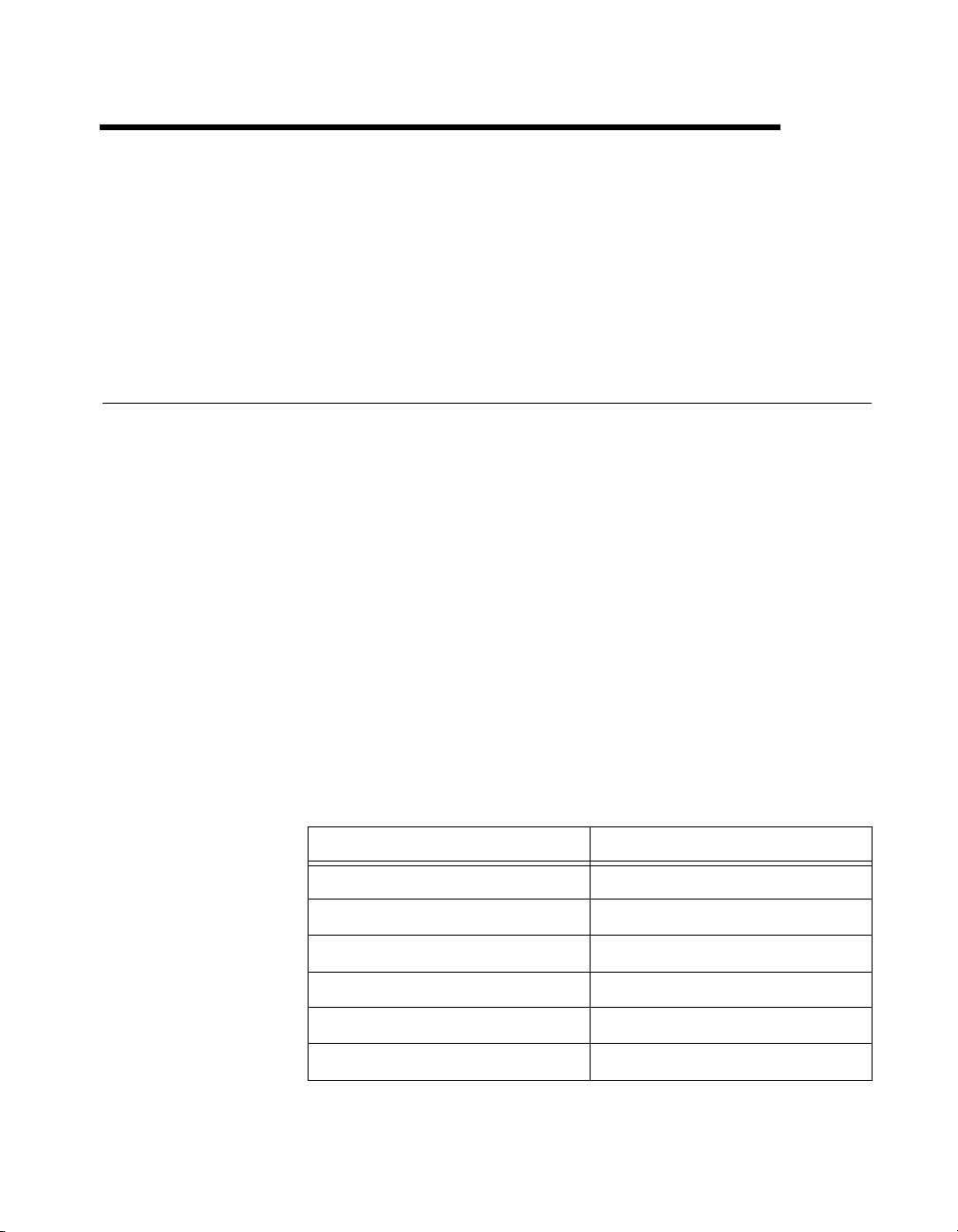
and custom cabling for your DAQ device. Table 1-1 lists the appropriate
DAQ board user manual for each of the RT Series DAQ boards.
1
Table 1-1.
RT Series DAQ Board DAQ Manual
PXI-7030/6040E PXI E Series User Manual
PXI-7030/6030E PXI E Series User Manual
PXI-7030/6533 DIO 6533 User Manual
PCI-7030/6040E PCI E Series User Manual
PCI-7030/6030E PCI E Series User Manual
PCI-7030/6533 DIO 6533 User Manual
© National Instruments Corporation 1-1 RT Series DAQ Device User Manual
RT Series DAQ Board and Corresponding DAQ Device Manual
Page 11

Chapter 1 Introduction
What You Need to Get Started
To set up and use your RT Series DAQ board, you need the following:
❑ One of the following boards:
– PXI-7030/6XXX
– PCI-7030/6XXX
❑ This manual
❑ Hardware user manual for your DAQ daughterboard, shown
in Table 1-1
❑ LabVIEW RT
❑ LabVIEW RT User Manual
❑ LabVIEW RT Release Notes
❑ NI-DAQ and the NI-DAQ documentation installed with the software
❑ Your computer
Unpacking
Your RT Series DAQ board is shipped in an antistatic package to prevent
electrostatic damage to the board. Electrostatic discharge can damage
several components on the board. To avoid such damage in handling the
board, take the following precautions:
• Ground yourself by using a grounding strap or by holding a grounded
object.
• Touch the antistatic package to a metal part of your computer chassis
before removing the board from the package.
• Remove the board from the package and inspect the board for
loose components or any other sign of damage. Notify National
Instruments if the board appears damaged in any way. Do not install
a damaged board into your computer.
• Never touch the exposed pins of connectors.
RT Series DAQ Device User Manual 1-2 www.ni.com
Page 12

Software Programming Choices
You can use the RT Series DAQ boards with LabVIEW RT and NI-DAQ.
NI-DAQ is included with LabVIEW RT and you can install it during the
LabVIEW RT installation. For specific information on LabVIEW RT and
NI-DAQ version compatibility, refer to your LabVIEW RT Release Notes.
Refer to Chapter 2, Installation and Configuration, for more information
about installing your RT Series hardware.
Chapter 1 Introduction
© National Instruments Corporation 1-3 RT Series DAQ Device User Manual
Page 13

Installation and Configuration
This chapter explains how to install and configure your RT Series DAQ
hardware.
Hardware Installation
You can install the RT Series DAQ board in any available expansion slot
in your computer or PXI chassis. However, to reduce noise, leave as much
room as possible between the RT Series DAQ board and other boards and
hardware. The following are general installation instructions, so refer to
your computer user manual or technical reference manual for specific
instructions and warnings about installing hardware.
Note
Install LabVIEW RT and NI-D A Q before you install your R T Series D A Q hardware.
Refer to Chapter 2, Installation, of the LabVIEW RT User Manual for more information
about installing LabVIEW RT and NI-DAQ.
PCI Installation
Complete the following steps to install your RT Series PCI board:
1. Write down the RT Series DAQ board serial number for future
reference.
2. Power off and unplug your computer.
3. Remove the cover to your computer.
4. Remove the expansion slot cover on the back panel of the computer.
5. Insert the RT Series DAQ board into a 5 V PCI slot. Gently rock the
board to ease it into place. It may be a tight fit, but do not force the
board into place.
6. Screw the mounting bracket of the RT Series DAQ board to the back
panel rail of the computer.
7. Replace the cover.
8. Plug in and power on your computer.
2
Your RT Series DAQ device is installed. You are now ready to configure
your software.
© National Instruments Corporation 2-1 RT Series DAQ Device User Manual
Page 14

Chapter 2 Installation and Configuration
PXI Installation
Complete the following steps to install your RT Series PXI board:
1. Write down the PXI E Series board serial number for future reference.
2. Power off and unplug your computer.
3. Choose two adjacent unused PXI slots in your system.
4. Remove the filler panels for the slots you have chosen.
5. Insert the RT Series DAQ board into the 5 V PXI slots. Use the
injector/ejector handle to fully insert the board into the chassis.
6. Screw the front panel of the RT Series DAQ board to the front panel
mounting rail of the system.
7. Plug in and power on your computer.
Your RT Series DAQ device is installed. You are now ready to configure
your software.
Board Configuration
Because of the National Instruments standard architecture for data
acquisition and the PCI and PXI bus specifications, the RT Series DAQ
boards are completely software configurable.
The PCI RT Series DAQ boards are fully compatible with the industry
standard PCI Local Bus Specification Revision 2.0. The PXI RT Series
DAQ boards are fully compatible with the PXI Specification Revision 1.0.
This compatibility allows the PCI or PXI system to automatically perform
all bus-related configurations and requires no user interaction.
DAQ-related configuration includes such settings as analog inp ut polarity
and range, analog input mode, and others. You also can configure virtual
channels, SCXI, and DAQ accessories. You can modify these settings
through Measurement & Automation Explorer and through LabVIEW RT
and NI-DAQ.
After you complete the installation, double-click the Measurement &
Automation Explorer icon on your desktop. Measurement & Automation
Explorer finds the RT Series DAQ board and any other DAQ boards you
have in your system and assigns device numbers to them. The RT Series
DAQ device appears in Measurement & Automation Explorer as shown in
Figure 2-1.
RT Series DAQ Device User Manual 2-2 www.ni.com
Page 15

Chapter 2 Installation and Configuration
Figure 2-1. Measurement & Automation Explorer
Notice that Measurement & Automation Explorer assigns separate device
numbers to the PCI/PXI-7030 device and the DAQ daughterboard, as
shown in Figure 2-1. The DA Q daughterboard is shown as a separate de vice
under the 7030. However, the daughterboard has a device number that is
different from the 7030.
Remember the device numbers of your R T Series DA Q hardware. You need
them to download and run LabVIEW RT VIs to your RT Series DAQ
boards.Y ou can change de vice numbers and other configuration settings for
the devices using Measurement & Automation Explorer. Changes to these
settings do not take effect on the RT Series DAQ board until you reset the
board.
You can test the resources of the 7030 using Measurement & Automation
Explorer. Ho wever , you cannot test resources or run test panels for the DA Q
daughterboard because even though the daughterboard is configured using
the host PC, the daughterboard is actually located on the local PCI bus of
the of the RT Series daughterboard. Only LabVIEW RT applications
targeted to the 7030 can access the DA Q daughterboard. For this reason, the
resource configuration on the PCI bus cannot be tested from the host PC.
You do not need to test the resource configuration because National
Instruments configures it and it does not change. In addition, applications
run on the host PC cannot access the DAQ daughterboard directly, even
© National Instruments Corporation 2-3 RT Series DAQ Device User Manual
Page 16

Chapter 2 Installation and Configuration
though the DAQ daughterboard is configured as a separate device. Only
LabVIEW RT applications targeted to the RT Series DAQ device can
access the DAQ daughterboard.
Tip If you want to test whether the DA Q daughterboard is working, run any DA Q example
that ships with LabVIEW RT.
Save the configuration information by selecting File»Save. Then close
Measurement & Automation Explorer.
RT Series DAQ Device User Manual 2-4 www.ni.com
Page 17

Hardware Overview
This chapter describes the PCI and PXI RT Series DAQ hardware. You can
find most of the hardware information you need in the DAQ board manual.
Table 1-1, RT Series DAQ Board and Corresponding DAQ Device Manual,
lists the DAQ board manuals for the various RT Series DAQ boards.
As shown in Figure 3-1 and Figure 3-2, a DAQ daughterboard attaches to
the processor board, and together they form the RT Series DAQ hardware.
The following sections describe the components that make up the R T Series
DAQ hardware.
3
Processor Board
DAQ Daughterboard
Figure 3-1.
© National Instruments Corporation 3-1 RT Series DAQ Device User Manual
PCI RT Series Real-Time Data Acquisition Hardware
Page 18

Chapter 3 Hardware Overview
Processor Board
DAQ
Daughterboard
Figure 3-2. PXI RT Series Real-Time Data Acquisition Hardware
Processor Board
The 7030 processor board contains a microprocessor and support circuitry,
as shown in Figure 3-3. The support circuitry includes a chipset with PCI
controller and ISA bridge, main memory (DRAM), L2 cache (SRAM), and
BIOS. The LabVIEW RT software uses this embedded processor system
for its execution platform.
The DAQ daughterboard resides on the embedded PCI bus as shown in
Figure 3-3. This provides a high-performance system for communication
between the software running on the processor and the DAQ
daughterboard.
The processor board also holds the shared memory that communicates
between the host system and the embedded processor. Refer to the
Host-to-RT Series DAQ Board Communication section later in this chapter
and to Chapter 3, Software Overview, of the LabVIEW RT User Manual,
for more information about using shared memory for your applications.
RT Series DAQ Device User Manual 3-2 www.ni.com
Page 19

Processor Board
CPU
Embedded CPU Bus
Chapter 3 Hardware Overview
BIOS
Host PCI Bus
MITE
DAQ Daughterboard
ISA Bridge
Controller
Embedded ISA Bus
Shared Memory
Interface
Shared
Memory
I/O Daughter Board
Figure 3-3. RT Series Processor Board Diagram
SRAM/DRAM
BIOS
Extension
Cache Memory
PCI Controller
Embedded PCI Bus
The daughterboard in the RT Series system provides the DAQ
functionality. Each daughterboard is a National Instruments PXI DAQ
device with some mechanical modifications to allow it to connect to
the processor board. This means that you can expect the same high
performance and specifications from the daughterboard that you do from
the standard version of the device. For example, the PCI/PXI-7030/6040E
boards have the same DAQ characteristics as the PXI-6040E. For this
reason, you should refer to appropriate daughterboard manual for
© National Instruments Corporation 3-3 RT Series DAQ Device User Manual
Page 20

Chapter 3 Hardware Overview
specifications, cabling requirements, and accessory information. Table 1-1,
RT Series DAQ Board and Corresponding DAQ Device Manual, lists the
appropriate manual for each available daughterboard. Refer to the DAQ
section of the LabVIEW Online Reference, available by selecting
Help»Online Reference in LabVIEW, for more information abou t
hardware and software configuration.
Host-to-RT Series DAQ Board Communication
The computer into which the RT Series DAQ board is installed is called the
host computer. The RT Series DAQ board communicates to the host
computer in which it resides through shared memory on the 7030 processor
board. Both the host computer and the embedded processor have access to
the shared memory. The memory is allocated for various tasks. For
example, the LabVIEW RT Development System, on the host, uses part of
the shared memory for downloading software to the board. There is also
some memory space allocated to the user for passing data between the host
computer and the processor board.
RTSI
The real-time system integration bus (RTSI bus) directly connects DAQ
boards for precise synchronization of functions. The RT Series boards
provide all RTSI functionality. The RTSI bus allows you to connect
RT Series boards to any other DAQ board regardless of whether the other
board is an RT Series board or standard DAQ board.
The R TSI connections are made across the PXI trigger bus for the PXI RT
boards. For PCI R T Series boards, the connection is made with a connector
on the top edge of the board and a RTSI cable available from National
Instruments. Refer to your daughterboard user manual for information
on how to use the RTSI signals. Table 1-1, RT Series DAQ Board and
Corresponding DAQ Device Manual, lists the appropriate manual for
each available daughterboard.
LEDs
There are two LEDs on the RT Series processor board. You can use these
LEDs to indicate the state of your running application. On the PXI-7030,
the LEDs are visible on the front panel. On the PCI-7030, the LEDs are
located along the top edge of the board, and you must remove the cover
from the case of your computer to view them.
RT Series DAQ Device User Manual 3-4 www.ni.com
Page 21

Chapter 3 Hardware Overview
The red LED turns on during a portion of the reset of the RT Series DAQ
board. Also, the red LED turns on and remains lighted if the RT Engine
detects an internal error. You can control both the red LED and a second
green LED from LabVIEW RT applications to provide status information.
You can use the RT Board LEDs VI, located in the Functions»RT»RT
Series DAQ»RT Board Utilities palette, in your application to control
each LED independently . You can turn each LED on, off, or toggle its state.
Refer to the LabVIEW RT Online Reference for more information on the
RT Board LEDs VI.
© National Instruments Corporation 3-5 RT Series DAQ Device User Manual
Page 22

LabVIEW RT Programming
This chapter provides an overview of using LabVIEW RT and your
RT Series DAQ hardware.
Targeting LabVIEW RT and Downloading VIs
In the LabVIEW RT Development System, select Operate»Switch
Execution Target to access the Select Target Platform dialog box, shown
in Figure 4-1.
4
Figure 4-1.
Use the pull-down menu to select where you want to run VIs. When you
select a target platform, the RT Development System downloads any VI
you subsequently run to that target platform. Selecting Host PC
(LabVIEW for Windows) makes LabVIEW RT behave like LabVIEW
for Windows on the host PC.
Any RT Series DAQ board that you configured with Measurement &
Automation Explorer appears in the pull-down menu. The menu selection
for each device displays the de vice number , for example, DAQ::1, where 1
is the device number . Click the Reset device checkbox in the Select Target
Platform dialog box to reset the RT Series DAQ device. Any VIs you
previously downloaded to the RT Series DAQ device are aborted and
© National Instruments Corporation 4-1 RT Series DAQ Device User Manual
Select Target Platform Dialog Box
Page 23

Chapter 4 LabVIEW RT Programming
unloaded from memory. Click Configure in the Select Target Platform
dialog box to launch Measurement & Automation Explorer and configure
your RT Series DAQ devices.
Resetting the RT Series DAQ Board
Resetting the RT Series DAQ board is necessary only after you first turn on
the system or if communication with the RT Engine cannot be established
or has been lost. Also, reset the board when you change the DAQ
configuration information for the RT Series DAQ board.
Creating Stand-Alone Executables
Use the Application Builder, included in the LabVIEW RT Professional
Development System, to create stand-alone LabVIEW RT applications.
Refer to the LabVIEW RT User Manual and the LabVIEW Application
Builder Release Notes for more information about the Application Builder.
Note
If you have the LabVIEW RT Full Development System, you can purchase the
Application Builder upgrade.
Embedded Applications
Because the RT Series DAQ hardware has no media storage device (for
example, a hard drive), you cannot permanently embed applications on the
hardware. You must launch applications on the host and target them to the
RT Series DAQ device.
Command-Line Arguments
You can use command-line arguments to disable the Select Target
Platform dialog box and explicitly specify a target for the application. You
can use the parameters in a batch file, or shortcut, from your Windows
StartUp folder to automatically launch RT Engine VIs when your host PC
is booted. For example, create a Windows shortcut with the shortcut target:
c:\mybuiltapp.exe -target DAQ::1 -quithost
This command line automatically downloads and runs mybuiltapp on
device 1 and closes the RT Development System on the host PC.
RT Series DAQ Device User Manual 4-2 www.ni.com
Page 24

T o disable the Select T arget Platform dialog box, specify the target platform
in the command line argument of your built e xecutable using
example:
c:\mybuiltapp_rtengine.exe -target DAQ::3 (for device 3)
or to run the application on the host PC:
c:\mybuiltapp_host.exe -target host
You also can reset the specified board using -reset. For example:
c:\mybuiltapp_rtengine.exe -target DAQ::3 -reset
T o disconnect the host PC from the R T Engine after all VIs are downloaded
and leave the RT Engine VIs running, use
c:\mybuiltapp_rtengine.exe -target DAQ::3 -quithost
Programming LabVIEW RT
Because you run LabVIEW RT on hardware platforms that do not have all
the components of a computer, LabVIEW RT lacks some LabVIEW
features when targeted to the RT Engine. For example, there is no disk
drive on the RT Series DAQ device, therefore, LabVIEW RT does not
support file I/O when targeted to the RT Series DAQ device. LabVIEW RT
does not support the following LabVIEW functions on RT Series DAQ
hardware:
•ActiveX
• Datalogging
• Dialog boxes
• Ethernet
•File I/O
• Instrument I/O: VISA, 488, RS-232/Serial
• Printing
•Profiler
• Programmatic Menu Bar
Chapter 4 LabVIEW RT Programming
–target. For
-quithost. For example:
Note
If you attempt to download to and run on your target platform a VI that has any of
the unsupported functionality listed above, the VI still executes. Unsupported functions do
not work and return standard LabVIEW error codes.
© National Instruments Corporation 4-3 RT Series DAQ Device User Manual
Page 25

Chapter 4 LabVIEW RT Programming
Real-Time Programming
This section provides an overview of real-time programming using your
RT Series DAQ hardware.
Running a VI at Time-Critical Priority without the RT Development System
Instead of using TCP/IP or VI Server to communicate data to a host PC
application, you can maximize real-time VI performance on RT Series
DAQ devices by peeking and poking data to shared memory. Peeking, or
reading directly from shared memory, and poking, or writing directly to
shared memory, are common programming techniques and do not require
the VI to yield any processor time. You can create deterministic control
loops that run in excess of 1 kHz when you peek and poke data to shared
memory. Refer to Chapter 3, Software Overview, of the LabVIEW RT User
Manual for more information about TCP/IP and VI Server.
Note
Windo ws NT does not support peeking and poking to shared memory on the PC.
However, because the shared memory is located on the RT Series DAQ device, Windows
NT does support peeking and poking to this shared memory.
Use of Shared Memory
Using peek and poke VIs to write directly to shared memory offers the best
performance. Because you can access shared memory both from a host
LabVIEW application and from an embedded LabVIEW RT VI, you can
write a control loop program that does not have to slow down or yield to
communicate with the host system. Many such examples are in the
examples\RT\RTControl.llb library.
Configuration Issues
The LabVIEW RT Development System downloads the RT Engine to the
RT Series DAQ hardware and sends configuration information when you
reset the hardware. If you make any change to the board configuration
information from Measurement & Automation Explorer, you must reset the
RT Series DAQ hardware for the changes to take effect.
LabVIEW RT also supports virtual channels, SCXI, and DA Q accessories
on the RT Series DAQ hardware, but their descriptions download to the
board when the board is reset. If you add a new channel or change the
parameters of a channel using Measurement & Automation Explorer, you
must reset the RT Series DAQ hardware for these changes to take effect.
RT Series DAQ Device User Manual 4-4 www.ni.com
Page 26

However, unlike virtual channels, you can set board parameters or
accessory configuration information programmatically inside a VI
without running Measurement & Automation Explorer. Therefore, you
can programmatically change these parameters in your VI, without
resetting the hardware.
Refer to your NI-DAQ documentation and the DAQ section of the
LabVIEW Online Reference, available by selecting Help»Online
Reference, for more information about configuration.
Activity 4-1. Communicating
with an Embedded VI
Your objective is to communicate with an embedded VI using shared
memory.
1. Open LabVIEW RT and select Operate»Switch Execution Target to
access the Select Target Platform dialog box.
2. Select the appropriate RT Series DAQ board from the Select Target
Platform dialog box. Click OK.
3. Run the Peek Poke I32 - RT Engine VI, found in the
Examples\RT\RTComm.llb library.
4. Select Operate»Switch Execution Target to close the
RT Development System but not the embedded VI.
5. Select Host PC (LabVIEW for Windows) from the Select Target
Platform dialog box. Run the Peek Poke I32 - Host PC VI, found in
the
Examples\RT\RTComm.llb library.
Refer to Windows»Show VI Info of these VIs for more information.
Chapter 4 LabVIEW RT Programming
Tip
Although peek and poke VIs are the low level, f astest form of communication, using
several of these VIs in a control loop can slow down your application. If you need a loop
with communication to run at maximum rates, use the R T Incremental Single Write VI and
R T Incrementa l Single Read VI, found on the RT»RT Series DAQ»RT Board Utilities
palette.
The size of the shared memory is limited to 1 kB. If you need to
transfer several megabytes of data, you must separate the data into
smaller portions and then transfer them. In doing so, you must make
sure that you do not overwrite data in the shared memory before you
read it. TCP/IP VIs manage flow control and are more convenient for
bulk transfers.
© National Instruments Corporation 4-5 RT Series DAQ Device User Manual
Page 27

Chapter 4 LabVIEW RT Programming
6. Open and run the TCP - RT Engine VI on the RT Series DAQ device.
You can find the VI in the
7. Select Operate»Switch Execution Target to close the
RT Development System but not the embedded VI.
8. Open and run the TCP - Host PC VI on the host PC. You can find the
VI in the
9. Exit LabVIEW RT by selecting File»Exit. Do not save changes.
This closes LabVIEW RT and stops and closes the TCP - RT Engine
VI on the RT Series DAQ device.
Examples\RT\RTComm.llb library.
End of Activity 4-1.
RT Series DAQ Functions
This section contains information about the RT Series DAQ VIs. Refer to
the LabVIEW RT Online Help, available by selecting Help»LabVIEW RT
Help, for more information about the LabVIEW RT VIs.
Examples\RT\RTComm.llb library.
RT Series DAQ VIs
In addition to the RT Series DAQ VIs, LabVIEW RT includes the PID
Control T oolset, which includes functions for PID and Fuzzy Logic control.
The Fuzzy Controller VI requires information for a specific designed fuzzy
controller loaded from its corresponding data file (
LabVIEW RT does not support file I/O, you must save this information as
the default values of the front panel controls of the Fuzzy Controller VI
before attempting to use it on the RT Series DA Q de vice. Refer to the PID
Control for G Reference Manual for more information about the PID
Control and Fuzzy Logic VIs.
You can find VIs specific to RT Series DAQ on the Functions»RT»RT
Series DAQ palette, as shown in Figure 4-2.
*.fc). Because
RT Series DAQ Device User Manual 4-6 www.ni.com
Page 28

Chapter 4 LabVIEW RT Programming
Figure 4-2. RT Series DAQ Functions Palette
RT Board Utilities VIs
Use the RT Board Utilities VIs to check the shared memory size, toggle the
board LEDs, and facilitate high-level communication between the
RT Series DAQ device and the host PC.
© National Instruments Corporation 4-7 RT Series DAQ Device User Manual
Page 29

Chapter 4 LabVIEW RT Programming
RT Shared Memory Read Write VIs
Use the RT Read Write VIs to read and write data from the shared memory
of your PXI or PCI-7030 RT Series DAQ device. The read and write shared
memory VIs differ from the peek and poke shared memory VIs in that the
read and write shared memory VIs use a read/write flag to determine if data
has changed.
RT Peek Poke with Error Cluster VIs
Use the RT Peek Poke VIs to peek and poke data to and from the shared
memory on the RT Series DAQ board. The RT Peek Poke VIs differ from
the RT Low-Level Peek Poke VIs in that they include the standard error
cluster and provide the next byte offset indicator.
RT Low-Level Peek Poke VIs
Use the RT Low-Level Peek Poke VIs to peek and poke data to and from
the shared memory on the RT Series DAQ board. The RT Low-Level Peek
Poke VIs differ from the RT Peek Poke with Error Cluster VIs in that they
do not include the standard error cluster nor provide the next byte offset
indicator.
RT Series DAQ Device User Manual 4-8 www.ni.com
Page 30

Specifications
This appendix lists the specifications of the embedded processor system.
Processor
Processor................................................AMD 486 DX5
Processor clock speed ............................133 MHz
CPU bus speed.......................................33 MHz
Memory........................................... .......8 MB DRAM user-programmable
On-chip cache ........................................ 16 KB write-back
L2 cache.................................................256 KB write-back
Floating-point unit..................................Yes
A
32-bit architecture
60 ns, EDO, 5 V,
72-Pin SODIMM
Host-Embedded Communication
Shared Memory
Type .......................................................SRAM
Size.........................................................1 KB user available
Bus Interface
Type .......................................................PCI Slave
© National Instruments Corporation A-1 RT Series DAQ Device User Manual
Page 31

Appendix A Specifications
Power Requirement
Note
T o calculate the total power requirement, add the processor board requireme nt from
this section to the I/O board requirement given in the I/O board manual.
Physical
PCI-7030 only (without
daughterboard)........................................1.9 A at +5 VDC (±5%)
PXI-7030 only (without
daughterboard)........................................2.0 A at +5 VDC (±5%)
Dimensions (Not Including Connectors)
PCI-7030.................................................312.9 by 160.5 cm
(12.3 by 4.2 in.)
One PCI slot
PXI-7030 ................................................16 by 10 cm (6.3 by 3.9 in.)
Two PXI slots
Environment
Operating temperature............................0 to 55 °C
Storage temperature................................–20 to 70 °C
Relative humidity ...................................10% to 90% noncondensing
RTSI
Refer to the RTSI section of Chapter 3, Hardware Overview.
I/O Daughterboard Specifications
Refer to the appropriate I/O board manual, listed in Table 1-1, RT Series
DAQ Board and Corresponding DAQ Device Manual, for more
information about I/O daughterboard specifications.
RT Series DAQ Device User Manual A-2 www.ni.com
Page 32

Technical Support Resources
This appendix describes the comprehensive resources available to yo u in
the Technical Support section of the National Instruments Web site and
provides technical support telephone numbers for you to use if you have
trouble connecting to our Web site or if you do not have internet access.
NI Web Support
To provide you with immediate answers and solutions 24 hours a day,
365 days a year, National Instruments maintains extensi ve online technical
support resources. They are available to you at no cost, are updated daily,
and can be found in the Technical Support section of our Web site at
www.ni.com/support
Online Problem-Solving and Diagnostic Resources
• KnowledgeBase—A searchable database containing thousands of
frequently asked questions (F A Qs) and their corresponding answers or
solutions, including special sections devoted to our newest products.
The database is updated daily in response to new customer experiences
and feedback.
• Troubleshooting Wizards—Step-by-step guides lead you through
common problems and answer questions about our entire product line.
Wizards include screen shots that illustrate the steps being described
and provide detailed information ranging from simple getting started
instructions to advanced topics.
• Product Manuals—A comprehensive, searchable library of the latest
editions of National Instruments hardware and software product
manuals.
• Hardware Reference Database—A searchable database containing
brief hardware descriptions, mechanical drawings, and helpful images
of jumper settings and connector pinouts.
• Application Notes—A library with more than 100 short papers
addressing specific topics such as creating and calling DLLs,
developing your own instrument driver software, and porting
applications between platforms and operating systems.
B
© National Instruments Corporation B-1 RT Series DAQ Device User Manual
Page 33

Appendix B Technical Support Resources
Software-Related Resources
• Instrument Driver Network—A library with hundreds of instrument
drivers for control of standalone instruments via GPIB, VXI, or serial
interfaces. You also can submit a request for a particular instrument
driver if it does not already appear in the library.
• Example Programs Database—A database with numerous,
non-shipping example programs for National Instruments
programming environments. You can use them to complement the
example programs that are already included with National Instruments
products.
• Software Library—A library with updates and patches to application
software, links to the latest versions of driver software for National
Instruments hardware products, and utility routines.
Worldwide Support
National Instruments has offices located around the globe. Many branch
offices maintain a Web site to provide information on local services. You
can access these Web sites from
www.ni.com/worldwide
If you have trouble connecting to our Web site, please contact your local
National Instruments office or the source from which you purchased your
National Instruments product(s) to obtain support.
For telephone support in the United States, dial 512 795 8248. For
telephone support outside the United States, contact your local branch
office:
Australia 03 9879 5166, Austria 0662 45 79 90 0, Belgium 02 757 00 20,
Brazil 011 284 5011, Canada (Calgary) 403 274 9391,
Canada (Ontario) 905 785 0085, Canad a (Québec) 514 694 8521,
China 0755 3904939, Denmark 45 76 26 00, Finland 09 725 725 11,
France 01 48 14 24 24, Germany 089 741 31 30, Greece 30 1 42 96 427,
Hong Kong 2645 3186, India 91805275406, Israel 03 6120092,
Italy 02 41309 1, Japan 03 5472 2970, Korea 02 596 7456,
Mexico (D.F.) 5 280 7625, Mexico (Monterrey) 8 357 7695,
Netherlands 0348 433466, New Zealand 09 914 0488,
Norway 32 27 73 00, Poland 0 22 528 94 06, Portugal 351 1 726 9011,
Singapore 2265886, Spain 91 640 0085, Sweden 08 587 895 00,
Switzerland 056 200 51 51, Taiwan 02 2528 7227,
United Kingdom 01635 523545
RT Series DAQ Device User Manual B-2 www.ni.com
Page 34

Glossary
Prefix Meanings Value
m- milli- 10
k- kilo- 10
M- mega- 10
G- giga- 10
Numbers/Symbols
% percent
+ positive of, or plus
– negative of, or minus
°degree
–3
3
6
9
A
A amperes
address character code that identifies a specific location (or series of locations) in
memory
B
b bit—one binary digit, either 0 or 1
B byte—eight related bits of data, an eight-bit binary number. Also used to
denote the amount of memory required to store one byte of data.
BIOS basic input/output system—BIOS functions are the fundamental level of
any PC or compatible computer. BIOS functions embody the basic
operations needed for successful use of the computer’s hardw are resources.
© National Instruments Corporation G-1 RT Series DAQ Device User Manual
Page 35

Glossary
bus the group of conductors that interconnect individual circuitry in a computer.
Typically, a bus is the expansion vehicle to which I/O or other devices are
connected. Examples of PC buses are the ISA and PCI bus.
C
C Celsius
cache high-speed processor memory that buff ers commonly used instructions or
data to increase processing throughput
channel pin or wire lead to which you apply or from which you read the analog or
digital signal. Analog signals can be single-ended or differential. For digital
signals, you group channels to form ports. Ports usually consist of either
four or eight digital channels.
clock hardware component that controls timing for reading from or writing to
groups
CPU central processing unit
D
DAQ data acquisition—(1) collecting and measuring electrical signals from
sensors, transducers, and test probes or fixtures and inputting them to a
computer for processing; (2) collecting and measuring the same kinds of
electrical signals with A/D and/or DIO boards plugged into a computer , and
possibly generating control signals with D/A and/or DIO boards in the
same computer
device a plug-in data acquisition board, card, or pad that can contain multiple
channels and conversion devices. Plug-in boards, PCMCIA cards, and
devices such as the DAQPad-1200, which connects to your computer
parallel port, are all examples of DAQ devices. SCXI modules are distinct
from devices, with the exception of the SCXI-1200, which is a hybrid.
DIO digital input/output
DRAM dynamic RAM
RT Series DAQ Device User Manual G-2 www.ni.com
Page 36

Glossary
H
hardware the physical components of a computer system, such as the circuit boards,
plug-in boards, chassis, enclosures, peripherals, and cables
Hz hertz—the number of scans read or updates written per second
I
I/O input/output—the transfer of data to/from a computer system involving
communications channels, operator interface devices, and/or data
acquisition and control interfaces
ISA industry standard architecture
K
K kilo—the prefix for 1,024, or 210, used with B in quantifying data or
computer memory
L
LabVIEW laboratory virtual instrument engineering workbench
LED light-emitting diode
library a fi le containing compiled object modules, each comprised of one of more
functions, that can be linked to other object modules that make use of these
functions. NIDAQMSC.LIB is a library that contains NI-DAQ functions.
The NI-DAQ function set is broken down into object modules so that only
the object modules that are relevant to your application are linked in, while
those object modules that are not relevant are not linked.
M
M Me ga, the standard metric prefix for 1 million or 106, when used with units
of measure such as volts and hertz
MB megabytes of memory
© National Instruments Corporation G-3 RT Series DAQ Device User Manual
Page 37

Glossary
N
NI-DAQ Nationa l In struments driver software for DAQ hardware
O
operating system base-level software that controls a computer , runs programs, interacts with
users, and communicates with installed hardware or peripheral devices
P
PCI Peripheral Component Interconnect—a high-performance expansion bus
architecture originally developed by Intel to replace ISA and EISA. It is
achieving widespread acceptance as a standard for PCs and work-stations;
it offers a theoretical maximum transfer rate of 132 Mbytes/s.
PID control a three-term control mechanism combining proportional, integral, and
derivative control actions. Also see proportional control, integral control,
and derivative control.
R
RAM random-access memory
real time a property of an event or system in which data is processed as it is acquired
instead of being accumulated and processed at a later time
resource locking a technique whereby a device is signaled not to use its local memory while
the memory is in use from the bus
S
shared memory memory that can be sequentially accessed by more than one controller or
processor but not simultaneously accessed. Also known as dual-mode
memory.
soft reboot restarting a computer witho ut cycling the power, usually through the
operating system
RT Series DAQ Device User Manual G-4 www.ni.com
Page 38

T
TCP Transmission Control Protocol
trigger any event that causes or starts some form of data capture
V
V volts
VI virtual instrument—(1) a combination of hardware and/or software
elements, typically used with a PC, that has the functionality of a classic
stand-alone instrument; (2) a LabVIEW software module (VI), which
consists of a front panel user interface and a block diagram program
VISA virtual instrument software architecture—a new driv er software
architecture developed by National Instruments to unify
instrumentation software GPIB, DAQ, and VXI. It has been accepted as
a standard for VXI by the VXIplug&play Systems Alliance.
Glossary
© National Instruments Corporation G-5 RT Series DAQ Device User Manual
Page 39

Index
B
board configuration, 2-2 to 2-4
bus interface specifications, A-1
C
command-line arguments, 4-2 to 4-3
communication
communicating with embedded VI
(activity 4-1), 4-5 to 4-6
host-embedded communication shared
memory, A-1
host-to-RT Series DAQ board
communication, 3-4
configuration
board configuration, 2-2 to 2-4
real-time programming issues, 4-4 to 4-5
conventions used in manual, xi-xii
D
DAQ devices. See RT Series DAQ devices.
DAQ functions. See RT series DAQ functions.
daughterboard
hardware overview, 3-3 to 3-4
specifications, A-2
diagnostic resources, online, B-1
documentation
about this manual, xi
conventions used in manual, xi-xii
devices and corresponding manual
(table), 1-1
related documentation, xii
downloading VIs, 4-1 to 4-2
E
embedded applications, 4-2
embedded VI, communicating with
(activity4-1), 4-5to4-6
environment specifications, A-2
executables. See stand-alone executables,
creating.
F
functions. See RT series DAQ functions.
H
hardware overview, 3-1 to 3-5
daughterboard, 3-3 to 3-4
host-to-RT Series DAQ board
communication, 3-4
LEDs, 3-4 to 3-5
PCI RT Series RT DAQ hardware
(figure), 3-1
processor board, 3-2 to 3 -3
PXI RT Series RT DAQ hardware
(figure), 3-2
RTSI bus, 3-4
host-embedded communication shared
memory, A-1
host-to-RT Series DAQ board
communication, 3-4
I
installation, 2-1 to 2-2
PCI boards, 2-1
PXI boards, 2-1
unpacking RT Series DAQ devices, 1-2
© National Instruments Corporation I-1 RT Series DAQ Device User Manual
Page 40

Index
L
LabVIEW functions not supported on DAQ
hardware, 4-3
LabVIEW RT programming, 4-1 to 4-8
creating stand-alone executables,
4-2 to 4-3
downloading VIs, 4-1 to 4-2
LabVIEW functions not supported on
DAQ hardware, 4-3
real-time programming, 4-4 to 4-6
communicating with embedded VI
(activity 4-1), 4-5 to 4-6
configuration issues, 4-4 to 4-5
running VI at time-critical
priority, 4-4
shared memory, 4-4
resetting RT Series DAQ board, 4-2
RT series DAQ functions, 4-6 to 4-8
RT Board Utilities VIs, 4-7
RT Low-Level Peek/Poke VIs, 4-8
RT Peek Poke with Error
Cluster VIs, 4-8
RT Series DAQ VIs, 4-6 to 4-7
RT Shared Memory Read
Write VIs, 4-8
targeting LabVIEW RT, 4-1 to 4-2
LEDs, 3-4 to 3-5
M
manual. See documentation.
Measurement & Automation
Explorer, 2-2 to 2-4
N
National Instruments Web support, B-1 to B-2
O
online problem-solving and diagnostic
resources, B-1
P
PCI boards. See also hardware overview.
installation, 2-1
PCI RT Series RT DAQ hardware
(figure), 3-1
Peek Poke VIs
RT Low-Level Peek/Poke VIs, 4-8
RT Peek Poke with Error Cluster VIs, 4-8
physical specifications, A-2
power requirement specifications, A-2
problem-solving and diagnostic resources,
online, B-1
processor board, 3-2 to 3-3
board diagram, 3-3
description, 3-2
specifications, A-1
programming. See LabVIEW RT
programming.
PXI boards. See also hardware overview.
installation, 2-1
PXI RT Series RT DAQ hardware
(figure), 3-2
RT Series DAQ Device User Manual I-2 www.ni.com
Page 41

Index
R
real-time programming, 4-4 to 4-6
communicating with embedded VI
(activity 4-1), 4-5 to 4-6
configuration issues, 4-4 to 4-5
running VI at time-critical priority
without RT Development System, 4-4
shared memory, 4-4
requirements for getting started, 1-2
resetting RT Series DAQ board, 4-2
RT Series DAQ devices. See also hardware
overview.
configuration, 2-2 to 2-4
devices and corresponding manual
(table), 1-1
installation, 2-1 to 2-2
overview, 1-1
programming. See LabVIEW RT
programming.
requirements for getting started, 1-2
software programming choices, 1-3
specifications, A-1 to A-2
unpacking, 1-2
RT Series DAQ functions, 4-6 to 4-8
RT Board Utilities VIs, 4-7
RT Low-Level Peek/Poke VIs, 4-8
RT Peek Poke with Error Cluster VIs, 4-8
RT Series DAQ Functions palette
(figure), 4-7
RT Series DAQ VIs, 4-6 to 4-7
RT Shared Memory Read Write VIs, 4-8
RTSI bus, 3-4
S
shared memory
communicating with embedded VI
(activity 4-1), 4-5 to 4-6
host-embedded communication shared
memory, A-1
real-time programming, 4-4
RT Shared Memory Read Write VIs, 4-8
software programming choices, 1-3
software-related resources, B-2
specifications, A-1 to A-2
stand-alone executables, creating, 4-2 to 4-3
command-line arguments, 4-2 to 4-3
embedded applications, 4-2
T
targeting LabVIEW RT, 4-1 to 4-2
technical support resources, B-1 to B-2
U
unpacking RT Series DAQ devices, 1-2
V
VIs
communicating with embedded VI
(activity 4-1), 4-5 to 4-6
downloading VIs, 4-1 to 4-2
RT Board Utilities VIs, 4-7
RT Low-Level Peek/Poke VIs, 4-8
RT Peek Poke with Error Cluster VIs, 4-8
RT Series DAQ VIs, 4-6 to 4-7
RT Shared Memory Read Write VIs, 4-8
W
Web support from National Instruments,
B-1 to B-2
online problem-solving and diagnostic
resources, B-1
software-related resources, B-2
Worldwide technical support, B-2
© National Instruments Corporation I-3 RT Series DAQ Device User Manual
 Loading...