

National Instruments RMX-4120, RMX-4121, RMX-4123, RMX-4122, RMX-4124 Installation Manual
...Page 1
SAFETY INFORMATION & INSTALLATION GUIDE
RMX Programmable Power Supplies
RMX-4120/4121/4122/4123/4124/4125/4126/4127
About the RMX Safety Information & Installation Guide
This guide is intended for users of the Regulated DC Power Supply and their instructors.
It is assumed that the reader has knowledge about electrical safety standards and the electrical
aspects of regulated DC power supplies.
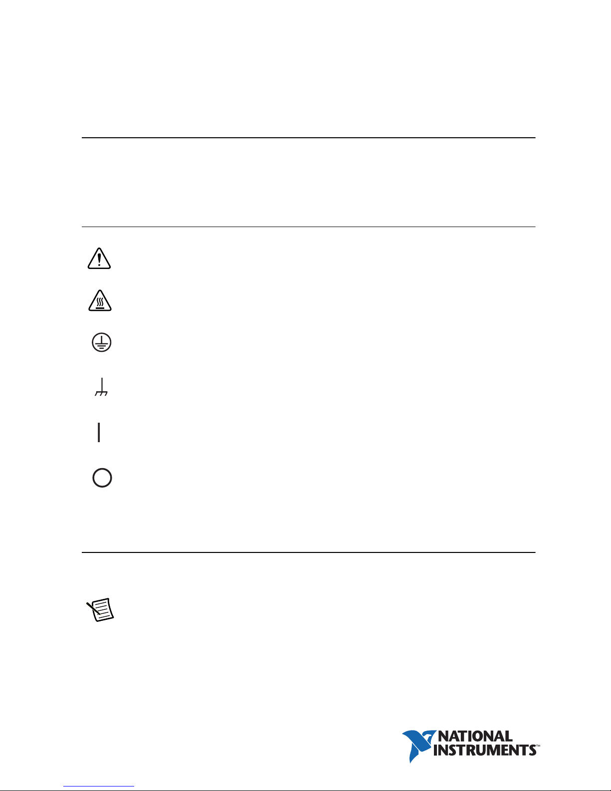
Safety Guidelines
Indicates general danger, warning, or caution. When this symbol is marked on the
product, see the relevant section in the operation manual.
Indicates a location whose surface can become hot.
Protective conductor terminal.
Chassis (frame) terminal.
On (supply).
Off (supply).
Installation and Preparation
This section describes how to turn on an RMX programmable power supply, what kind of load
cables to use, and how to connect cables to the output connectors.
Note Protection provided by this equipment may be impaired if it is used in a
manner not described in the manual.
Page 2

Connecting the Power Cord
This product is a piece of equipment that conforms to IEC Overvoltage Category II (equipment
that consumes energy supplied from a fixed installation).
A power cord is not included with the RMX-4124/4125/4126/4127. Use a power cord that
conforms to this product’s rated AC input voltage, input current, and configured for the
plug type. Refer to your product specifications for details.
Caution Risk of electric shock. This product is a piece of equipment that conforms
to IEC Safety Class I (equipment that has a protective conductor terminal). Be sure
to earth ground the product to prevent electric shock. The product is grounded
through the power cord ground wire. Connect the protective conductor terminal to
earth ground.
RMX-4120/4121/4122/4123 (750 W Models)
Necessary Cable
• North America—Extra Hard Usage Cord, min. 300 V, 60 C, 14 AWG, 3 Conductor cord,
3 m or less with a NEMA 5-15P to C14.
• Europe—HAR Marked, min. 300 V, 60 C, 2.5mm
plug configured for the country of use to C14.
2
, 3 Conductor cord, 3 m or less with a
• International—Certified for country of use, min. 300 V, 60 C, 2.5mm2, 3 Conductor cord,
3 m or less with a plug configured for the country of use to C14.
The power cord can be used to disconnect the RMX programmable power supply from the
AC power line in an emergency. Connect the plug to an easily accessible power outlet so that the
plug can be removed from the outlet at any time. Be sure to provide adequate clearance around
the power outlet.
1. Check that the AC power line meets the nominal input rating of the product. The product
can receive a nominal line voltage in the range of 100 VAC to 240 VAC at 50 Hz or 60 Hz.
2. Check that the POWER switch is turned off.
3. Connect the power cord to the AC inlet on the rear panel.
4. Insert the power plug into a grounded outlet.
2 | ni.com | RMX Programmable Power Supplies Safety Information & Installation Guide
Page 3

RMX-4124/4125/4126/4127 (1500 W Models)
Caution Risk of electric shock. Before you connect the power cord, turn off the
switchboard breaker (a switch that cuts off the power supply from the switchboard).
Risk of fire. Connection to the switchboard must be performed by a person who has
knowledge about electrical safety standards and the electrical aspects of regulated DC
power supplies. The switchboard breaker must meet the requirements shown below.
Caution Inside the product, protective circuits are connected to match the polarity
of the input terminal. Be sure to connect the L, N, and (GND) terminals of the product
to the matching terminals on the switchboard.
In an emergency, turn off the switchboard breaker to disconnect the product from the AC power line.
Necessary Cable
• Vinyl cabtire cable (VCTF): Nominal cross-sectional area 5.5 mm2, 3 core
• Finished diameter: 10.5 to 14.4 mm in diameter
• Rated voltage: 250 V or higher
• Input terminal end: 14 mm of insulation stripped from conductor for the L and N wires.
Crimping terminal (round, M4) that fixes the cable insulation in place
for the GND wire.
• Length: 3 m or less
Switchboard Breaker Requirements
• Installation must be done in accordance with national wiring rules, such as NFPA 70 "NEC"
and CSA C22.1 "CEC".
• Rated current: 30 A (for safety, breakers whose rated current exceeds 30 A cannot be used)
• Do not power any other equipment from the switchboard breaker.
• Keep the breaker readily accessible at all times.
• Indicate that the breaker is dedicated for use with this product and that it is used to
disconnect the product from the AC power line.
RMX Programmable Power Supplies Safety Information & Installation Guide | © National Instruments | 3
Page 4
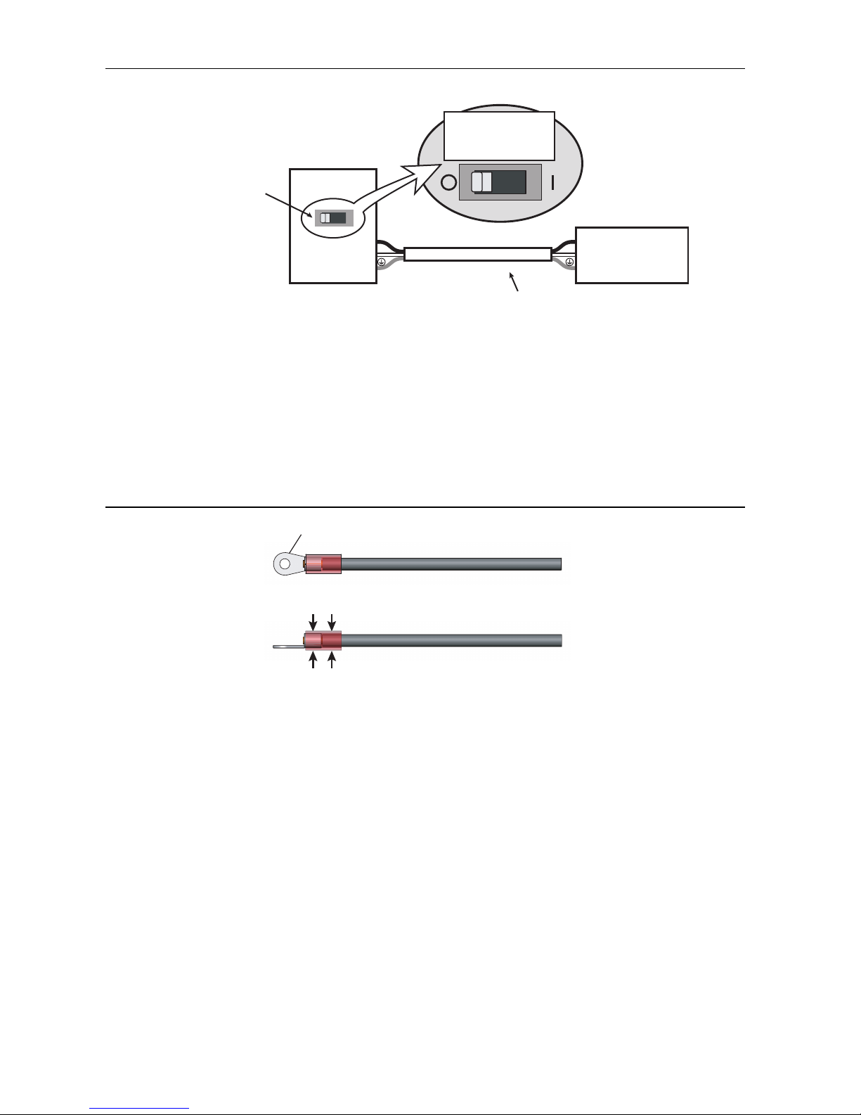
Figure 1. Switchboard Diagram
RMX-4125
Switchboard
N
L
N
L
Breaker indication example
For the
RMX-4125 only
30 A
Power cord
RMX-4125
dedicated breaker
Crimping terminal (round, M4)
When crimping the core wire, use a
crimping terminal and tool that can
also grip the insulation.
Connection Procedure
1. Check that the AC power line meets the nominal input rating of the product. The product
can receive a nominal line voltage in the range of 100 VAC to 240 VAC at 50 Hz or 60 Hz.
2. Check that the POWER switch is turned off.
3. Attach a crimping terminal to the GND wire.
Figure 2. Attaching the Crimping Terminal
4. Connect the power cord and the included INPUT terminal cover to the AC INPUT terminal
on the rear panel. Be sure to connect the AC INPUT L, N, and (GND) terminals correctly.
Pass the power cord through the INPUT terminal cover, and fix the cord in place using the
cable gland.
4 | ni.com | RMX Programmable Power Supplies Safety Information & Installation Guide
Page 5
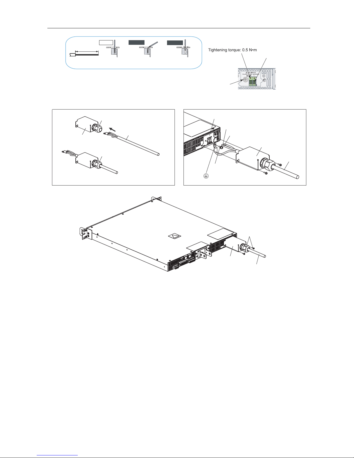
Figure 3. Connecting the Power Cord
STRIP-GAUGE
14 mm
Correct
Incorrect
Incorrect
The stripped wire is
touching the chassis.
The wire strands are
touching the chassis.
INPUT terminal cover
INPUT terminal cover
INPUT terminal cover
AC INPUT terminal
L: Black or brown
N: White or blue
(GND)
Screw
: Green or green and yellow
Power cord
Power cord
Power cord
Screw
Use this screw to fix the
wire in place.
Screw M4
Remove the first
14 mm of the wire’s
covering, and then
insert the wire here.
AC INPUT terminal
Cable gland:
Turn left to unlock
Cable gland:
Turn right to lock
Cable gland: Supports wires from 10.5 to 14.4 mm in diameter
5. Attach an appropriate crimping terminal to the switchboard end of the power cord.
6. Turn off the switchboard breaker.
7. Connect the L, N, and (GND) wires of the power cord to the matching terminals on the
switchboard.
RMX Programmable Power Supplies Safety Information & Installation Guide | © National Instruments | 5
Page 6

Turning the Power On
- (negative) terminal + (positive) terminal
Chassis terminal
Turning the POWER Switch On
Caution Risk of electric shock. Regardless of whether load cables are connected to
the output terminals, be sure to attach the OUTPUT terminal cover before turning the
POWER switch on.
Load Cables
Caution Risk of fire. Use load cables whose capacity is adequate for the RMX
programmable power supply’s rated output current. The output connector and its
surrounding area become hot. Use cables whose covers have heat resistance at 85 °C
and higher.
Caution Risk of electric shock. Use the cable which has higher withstanding voltage
than the specified insulation voltage of the product to secure the double insulation or
reinforced insulation.
Connecting to the Output Terminals
Caution Risk of electric shock. Turn the POWER switch off before you touch the
OUTPUT terminals. Even if you turn the output off or turn the POWER switch off,
if the bleeder on/off setting (CF11) is set to “OFF,” the voltage that was present when
the output was on will remain at the output terminals. Turn the bleeder circuit on
before you touch the output terminals. Regardless of whether load cables are
connected to the output terminals, be sure to attach the OUTPUT terminal cover
before turning the POWER switch on. Confirm that the voltage between any output
terminal and ground is lower than the isolation voltage of the RMX programmable
power supply.
Figure 4. RMX-4125 Output Terminal
6 | ni.com | RMX Programmable Power Supplies Safety Information & Installation Guide
Page 7

1. Turn the POWER switch off. Check that there is no voltage across the output terminals.
Chassis
connection wire
Screw (M3)
Screw (M4)
Chassis
connection wire
Screw (M3)
Screw (M4)
2. Connect one end of the included chassis connection wire to the chassis terminal, and then
connect the other end of the wire to the negative or positive output terminal.
Note For safety reasons, connect one of the output terminals to the chassis terminal
unless your application requires the output terminals to be floating
Use the screw on the RMX to connect the wire to the chassis terminal. Use the screw on the
output terminal to connect the wire to the output terminal.
Figure 5. RMX-4120/4121/4124/4125
Figure 6. RMX-4122/4123/4126/4127
3. Attach crimping terminals to the load cables.
The output terminals have holes for connecting the load cables. Use crimping terminals that
are appropriate for the bolts that you are using.
4. Use the included bolt set to connect the load cables to the output terminals.
Connect the positive cable to the positive output terminal and the negative cable to the
negative output terminal. The orientation of the crimping terminals will vary depending on
the wire diameter of the load cables used.
RMX Programmable Power Supplies Safety Information & Installation Guide | © National Instruments | 7
Page 8

Figure 7. Connection Using M8 Bolt Set for RMX-4120/4121/4124/4125
Spring washer
Washer
Nut
Bolt (M8)
Crimping terminal
Attach the cable to the inner side
of the crimping terminal.
Attach the cable to the outer side
of the crimping terminal.
Spring washer
Washer
Nut
Bolt (M5)
Screw (M4)
Figure 8. Connection Using M5 Bolt Set for RMX-4122/4123/4126/4127
Crimping terminal
Note If you do not connect load cables in the correct orientation, you will not be
able to attach the OUTPUT terminal cover.
8 | ni.com | RMX Programmable Power Supplies Safety Information & Installation Guide
Page 9

Attaching the Output Terminal Cover
Remove the screws, and then
line up the half of the cover.
You can adjust the diameter of the holes that the load cables pass through by changing the
positions in which the top and bottom halves of the OUTPUT terminal cover are put together.
There are two available positions. Use the appropriate position for the load cables that you are
using.
• For cables that are up to 10 mm in diameter: Put the top and bottom halves of the OUTPUT
terminal cover together so that the hole diameter is small.
• For cables that are between 10 mm and 18 mm in diameter: Put the top and bottom halves
of the OUTPUT terminal cover together so that the hole diameter is large.
1. Remove the screw that is attached next to the output terminals on the RMX. Use this screw
to attach the OUTPUT terminal cover.
2. Place the bottom half of the OUTPUT terminal cover underneath the load cables connected
to the output terminals.
Figure 9. Attaching Bottom Half of the OUTPUT Terminal Cover
Note The top and bottom halves of the OUTPUT terminal cover have different
shapes.
3. Align the tabs of the top half of the OUTPUT terminal cover with those of the bottom half.
Align the tabs of the OUTPUT terminal cover according to the load cable diameter.
RMX Programmable Power Supplies Safety Information & Installation Guide | © National Instruments | 9
Page 10

Figure 10. Aligning Both Halves of the OUTPUT Terminal Cover
Top half of the cove
Align the protrusion of
the top half of the cover
with the top section
of the protrusion of the
bottom half.
Bottom half of the cover
For thick load cables
Cover hole diameter:
10 mm to 18 mm
Cover hole diameter:
Up to 10 mm
For thin load cables
Top half of the cover
Align the protrusion of
the top half of the cover
with the middle section
of the protrusion of the
bottom half of the cover.
Bottom half of the cover
Middle
section
Top section
After you have lined up the top and bottom halves
of the cover, use the screws to fix the cover in place.
Screws (M3)
4. Push the OUTPUT terminal cover against the rear panel, and then use the RMX screws to
fix the cover in place. Ensure that the screws are securely fastened.
Figure 11. Attaching the OUTPUT Terminal Cover
10 | ni.com | RMX Programmable Power Supplies Safety Information & Installation Guide
Page 11

Specifications
RMX-4120/4121/4122/4123
AC Input
Nominal input rating......................................... 100 to 240 VAC, 50 to 60 Hz, single phase
Input voltage range ........................................... 85 to 265 VAC
Input frequency................................................. 47 to 63 Hz
Current (MAX)
100 VAC................................................... 10.5 A
200 VAC................................................... 5.25 A
Environmental conditions
Operating environment ............................. Indoor use, overvoltage category II
Operating temperature .............................. 0 to 50 °C (32 to 122 °F)
Operating humidity................................... 20 to 85% rh (no condensation)
Altitude ..................................................... Up to 2,000 m
Pollution degree ........................................ 2
1
RMX-4124/4125/4126/4127
AC Input
Nominal input rating......................................... 100 to 240 VAC, 50 to 60 Hz, single phase
Input voltage range ........................................... 85 to 265 VAC
Input frequency................................................. 47 to 63 Hz
Current (MAX)
100 VAC................................................... 21 A
200 VAC................................................... 10.5 A
Environmental conditions
Operating environment ............................. Indoor use, overvoltage category II
Operating temperature .............................. 0 to 50 °C (32 to 122 °F)
Operating humidity................................... 20 to 85% rh (no condensation)
Altitude ..................................................... Up to 2,000 m
Pollution degree ........................................ 2
1
1
With the rated load.
RMX Programmable Power Supplies Safety Information & Installation Guide | © National Instruments | 11
Page 12

Safety
This product is designed to meet the requirements of the following standards of safety for
electrical equipment for measurement, control, and laboratory use:
• IEC/EN 61010-1
• UL 61010-1
• CSA C22.2 No. 61010-1
Note For safety certifications, refer to the product label or the Online Product
Certification section.
Electromagnetic Compatibility
This product meets the requirements of the following EMC standards for electrical equipment
for measurement, control, and laboratory use:
• EN 61326-1 (IEC 61326-1): Class A emissions; Basic immunity
• EN 55011 (CISPR 11): Group 1, Class A emissions
AS/NZS CISPR 11: Group 1, Class A emissions
• FCC 47 CFR Part 15B: Class A emissions
• ICES-001: Class A emissions
Note In the United States (per FCC 47 CFR), Class A equipment is intended for use
in commercial, light industrial, and heavy industrial locations. In Europe, Canada,
Australia, and New Zealand (per CISPR 11), Class A equipment is intended for use
only in heavy industrial locations.
Note Group 1 equipment (per CISPR 11) is any industrial, scientific, or medical
equipment that does not intentionally generate radio frequency energy for the
treatment of material or inspection/analysis purposes.
Note For EMC declarations and certifications and additional information, refer to
the Online Product Certification section.
12 | ni.com | RMX Programmable Power Supplies Safety Information & Installation Guide
Page 13

CE Compliance
⬉ᄤֵᙃѻક∵ᶧࠊㅵ⧚ࡲ⊩ ˄Ё
RoHS
˅
Ёᅶ᠋
National Instruments
ヺড়Ё⬉ᄤֵᙃѻકЁ䰤ࠊՓ⫼ᶤѯ᳝ᆇ⠽䋼ᣛҸ
(RoHS)
DŽ݇Ѣ
National Instruments
Ё
RoHS
ড়㾘ᗻֵᙃˈ䇋ⱏᔩ
ni.com/
environment/rohs_china
DŽ
(For information about China RoHS compliance,
go to
ni.com/environment/rohs_china
.)
This product meets the essential requirements of applicable European Directives as follows:
• 2014/35/EU; Low-Voltage Directive (safety)
• 2014/30/EU; Electromagnetic Compatibility Directive (EMC)
• 2011/65/EU; RoHS
Online Product Certification
Refer to the product Declaration of Conformity (DoC) for additional regulatory compliance
information. To obtain product certifications and the DoC for this product, visit ni.com/
certification
, search by model number or product line, and click the appropriate link in the
Certification column.
Environmental Management
NI is committed to designing and manufacturing products in an environmentally responsible
manner. NI recognizes that eliminating certain hazardous substances from our products is
beneficial to the environment and to NI customers.
For additional environmental information, refer to the Minimize Our Environmental Impact web
page at
directives with which NI complies, as well as other environmental information not included in
this document.
ni.com/environment. This page contains the environmental regulations and
Waste Electrical and Electronic Equipment (WEEE)
EU Customers At the end of the product life cycle, all products must be sent to
a WEEE recycling center. For more information about WEEE recycling centers,
National Instruments WEEE initiatives, and compliance with WEEE Directive
2002/96/EC on Waste and Electronic Equipment, visit
.
weee
ni.com/environment/
RMX Programmable Power Supplies Safety Information & Installation Guide | © National Instruments | 13
Page 14

Worldwide Support and Services
The NI website is your complete resource for technical support. At ni.com/support you have
access to everything from troubleshooting and application development self-help resources to
email and phone assistance from NI Application Engineers.
ni.com/services for NI Factory Installation Services, repairs, extended warranty, and
Visit
other services.
ni.com/register to register your NI product. Product registration facilitates technical
Visit
support and ensures that you receive important information updates from NI.
A Declaration of Conformity (DoC) is our claim of compliance with the Council of the European
Communities using the manufacturer’s declaration of conformity. This system affords the user
protection for electromagnetic compatibility (EMC) and product safety. You can obtain the DoC
for your product by visiting
you can obtain the calibration certificate for your product at ni.com/calibration.
NI corporate headquarters is located at 11500 North Mopac Expressway, Austin, Texas,
78759-3504. NI also has offices located around the world. For telephone support in the United
States, create your service request at
For telephone support outside the United States, visit the Worldwide Offices section of
ni.com/niglobal to access the branch office websites, which provide up-to-date contact
information, support phone numbers, email addresses, and current events.
ni.com/certification. If your product supports calibration,
ni.com/support or dial 1 866 ASK MYNI (275 6964).
14 | ni.com | RMX Programmable Power Supplies Safety Information & Installation Guide
Page 15

Refer to the NI Trademarks and Logo Guidelines at ni.com/trademarks for more information on NI trademarks. Other product and company
names mentioned herein are trademarks or trade names of their respective companies. For patents covering NI products/technology, refer to the
appropriate location: Help»Patents in your software, the patents.txt file on your media, or the National Instruments Patents Notice at
ni.com/patents. You can find information about end-user license agreements (EULAs) and third-party legal notices in the readme file for your
NI product. Refer to the Export Compliance Information at ni.com/legal/export-compliance for the NI global trade compliance policy
and how to obtain relevant HTS codes, ECCNs, and other import/export data. NI MAKES NO EXPRESS OR IMPLIED WARRANTIES AS TO THE
ACCURACY OF THE INFORMATION CONTAINED HEREIN AND SHALL NOT BE LIABLE FOR ANY ERRORS. U.S. Government Customers: The data
contained in this manual was developed at private expense and is subject to the applicable limited rights and restricted data rights as set forth in
FAR 52.227-14, DFAR 252.227-7014, and DFAR 252.227-7015.
© 2016-2017 National Instruments. All rights reserved.
PART NO. Z1-006-662, IB031511 Feb17
 Loading...