

Page 1

RMX
RMX Programmable Power Supplies User Manual
RMX-4120
RMX-4121
RMX-4122
RMX-4123
RMX-4124
RMX-4125
RMX-4126
RMX-4127
RMX Programmable Power Supplies User Manual
February 2017
375744C-01
Page 2

About the RMX User Manual
This manual is intended for users of the Regulated DC Power Supply and their instructors.
It is assumed that the reader has knowledge about electrical safety standards and the electrical
aspects of regulated DC power supplies.
Safety Guidelines
Indicates general danger, warning, or caution. When this symbol is marked on the
product, see the relevant section in the operation manual.
Indicates a location whose surface can become hot.
Protective conductor terminal.
Chassis (frame) terminal.
On (supply).
Off (supply).
Support
Worldwide Technical Support and Product Information
ni.com
Worldwide Offices
Visit ni.com/niglobal to access the branch office Web sites, which provide up-to-date
contact information, support phone numbers, email addresses, and current events.
National Instruments Corporate Headquarters
11500 North Mopac Expressway Austin, Texas 78759-3504 USA Tel: 512 683 0100
For further support information, refer to the NI Services appendix. To comment on National
Instruments documentation, refer to the National Instruments website at
enter the Info Code feedback.
© 2016-2017 National Instruments. All rights reserved.
ni.com/info and
Page 3

Legal Information
Limited Warranty
This document is provided ‘as is’ and is subject to being changed, without notice, in future editions. For the latest version,
refer to
ni.com/manuals. NI reviews this document carefully for technical accuracy; however, NI MAKES NO EXPRESS
OR IMPLIED WARRANTIES AS TO THE ACCURACY OF THE INFORMATION CONTAINED HEREIN AND
SHALL NOT BE LIABLE FOR ANY ERRORS.
NI warrants that its hardware products will be free of defects in materials and workmanship that cause the product to fail to
substantially conform to the applicable NI published specifications for one (1) year from the date of invoice.
For a period of ninety (90) days from the date of invoice, NI warrants that (i) its software products will perform substantially
in accordance with the applicable documentation provided with the software and (ii) the software media will be free from
defects in materials and workmanship.
If NI receives notice of a defect or non-conformance during the applicable warranty period, NI will, in its discretion: (i) repair
or replace the affected product, or (ii) refund the fees paid for the affected product. Repaired or replaced Hardware will be
warranted for the remainder of the original warranty period or ninety (90) days, whichever is longer. If NI elects to repair or
replace the product, NI may use new or refurbished parts or products that are equivalent to new in performance and reliability
and are at least functionally equivalent to the original part or product.
You must obtain an RMA number from NI before returning any product to NI. NI reserves the right to charge a fee for
examining and testing Hardware not covered by the Limited Warranty.
This Limited Warranty does not apply if the defect of the product resulted from improper or inadequate maintenance,
installation, repair, or calibration (performed by a party other than NI); unauthorized modification; improper environment;
use of an improper hardware or software key; improper use or operation outside of the specification for the product; improper
voltages; accident, abuse, or neglect; or a hazard such as lightning, flood, or other act of nature.
THE REMEDIES SET FORTH ABOVE ARE EXCLUSIVE AND THE CUSTOMER’S SOLE REMEDIES, AND SHALL
APPLY EVEN IF SUCH REMEDIES FAIL OF THEIR ESSENTIAL PURPOSE.
EXCEPT AS EXPRESSLY SET FORTH HEREI N, PRODUCTS ARE PROVIDED "AS IS" WITHOUT WARRANTY OF
ANY KIND AND NI DISCLAIMS ALL WARRANTIES, EXPRESSED OR IMPLIED, WITH RESPECT TO THE
PRODUCTS, INCLUDING ANY IMPLIED WARRANTIES OF MERCHANTABILITY, FITNESS FOR A
PARTICULAR PURPOSE, TITLE OR NON-INFRINGEMENT, AND ANY WARRANTIES THAT MAY ARISE FROM
USAGE OF TRADE OR COURSE OF DEALING. NI DOES NOT WARRANT, GUARANTEE, OR MAKE ANY
REPRESENTATIONS REGARDING THE USE OF OR THE RESULTS OF THE USE OF THE PRODUCTS IN TERMS
OF CORRECTNESS, ACCURACY, RELIABILITY, OR OTHERWISE. NI DOES NOT WARRANT THAT THE
OPERATION OF THE PRODUCTS WILL BE UNINTERRUPTED OR ERROR FREE.
In the event that you and NI have a separate signed written agreement with warranty terms covering the products, then the
warranty terms in the separate agreement shall control.
Copyright
Under the copyright laws, this publication may not be reproduced or transmitted in any form, electronic or mechanical,
including photocopying, recording, storing in an information retrieval system, or translating, in whole or in part, without the
prior written consent of National Instruments Corporation.
National Instruments respects the intellectual property of others, and we ask our users to do the same. NI software is protected
by copyright and other intellectual property laws. Where NI software may be used to reproduce software or other materials
belonging to others, you may use NI software only to reproduce materials that you may reproduce in accordance with the
terms of any applicable license or other legal restriction.
End-User License Agreements and Third-Party Legal Notices
You can find end-user license agreements (EULAs) and third-party legal notices in the following locations:
• Notices are located in the
directories.
• EULAs are located in the
•Review
<National Instruments>\_Legal Information.txt for information on including legal information in
installers built with NI products.
U.S. Government Restricted Rights
If you are an agency, department, or other entity of the United States Government (“Government”), the use, duplication,
reproduction, release, modification, disclosure or transfer of the technical data included in this manual is governed by the
Restricted Rights provisions under Federal Acquisition Regulation 52.227-14 for civilian agencies and Defense Federal
Acquisition Regulation Supplement Section 252.227-7014 and 252.227-7015 for military agencies.
Trademarks
Refer to the NI Trademarks and Logo Guidelines at ni.com/trademarks for more information on National Instruments
trademarks.
ARM, Keil, and µVision are trademarks or registered of ARM Ltd or its subsidiaries.
LEGO, the LEGO logo, WEDO, and MINDSTORMS are trademarks of the LEGO Group.
TETRIX by Pitsco is a trademark of Pitsco, Inc.
FIELDBUS FOUNDATION
<National Instruments>\_Legal Information and <National Instruments>
<National Instruments>\Shared\MDF\Legal\license directory.
™
and FOUNDATION™ are trademarks of the Fieldbus Foundation.
Page 4

EtherCAT® is a registered trademark of and licensed by Beckhoff Automation GmbH.
®
CANopen
DeviceNet
Go!, SensorDAQ, and Vernier are registered trademarks of Vernier Software & Technol ogy. Vernier Software & Technology
and
is a registered Community Trademark of CAN in Automation e.V.
™
and EtherNet/IP™ are trademarks of ODVA.
vernier.com are trademarks or trade dress.
Xilinx is the registered trademark of Xilinx, Inc.
Taptite and Trilobular are registered trademarks of Research Engineering & Manufacturing Inc.
®
is the registered trademark of Apple Inc.
FireWire
®
Linux
is the registered trademark of Linus Torvalds in the U.S. and other countries.
®
Handle Graphics
trademarks, and TargetBox
Tektronix
The Bluetooth
The ExpressCard
license.
The mark LabWindows is used under a license from Microsoft Corporation. Windows is a registered trademark of Microsoft
Corporation in the United States and other countries.
, MATLAB®, Real-Time Workshop®, Simulink®, Stateflow®, and xPC TargetBox® are registered
™
®
, Tek, and Tektronix, Enabling Technology are registered trademarks of Tektronix, Inc.
®
word mark is a registered trademark owned by the Bluetooth SIG, Inc.
™
and Target Language Compiler™ are trademarks of The MathWorks, Inc.
word mark and logos are owned by PCMCIA and any use of such marks by National Instruments is under
Other product and company names mentioned herein are trademarks or trade names of their respective companies.
Members of the National Instruments Alliance Partner Program are business entities independent from National Instruments
and have no agency, partnership, or joint-venture relationship with National Instruments.
Patents
For patents covering National Instruments products/technology, refer to the appropriate location: Help»Patents in your
software, the
patents.txt file on your media, or the National Instruments Patent Notice at ni.com/patents.
Export Compliance Information
Refer to the Export Compliance Information at ni.com/legal/export-compliance for the National Instruments global
trade compliance policy and how to obtain relevant HTS codes, ECCNs, and other import/export data.
WARNING REGARDING USE OF NATIONAL INSTRUMENTS PRODUCTS
YOU ARE ULTIMATELY RESPONSIBLE FOR VERIFYING AND VALIDATING THE SUITABILITY AND
RELIABILITY OF THE PRODUCTS WHENEVER THE PRODUCTS ARE INCORPORATED IN YOUR SYSTEM OR
APPLICATION, INCLUDING THE APPROPRIATE DESIGN, PROCESS, AND SAFETY LEVEL OF SUCH SYSTEM
OR APPLICATION.
PRODUCTS ARE NOT DESIGNED, MANUFACTURED, OR TESTED FOR USE IN LIFE OR SAFETY CRITICAL
SYSTEMS, HAZARDOUS ENVIRONMENTS OR ANY OTHER ENVIRONMENTS REQUIRING FAIL-SAFE
PERFORMANCE, INCLUDING IN THE OPERATION OF NUCLEAR FACILITIES; AIRCRAFT NAVIGATION; AIR
TRAFFIC CONTROL SYSTEMS; LIFE SAVING OR LIFE SUSTAINING SYSTEMS OR SUCH OTHER MEDICAL
DEVICES; OR ANY OTHER APPLICATION IN WHICH THE FAILURE OF THE PRODUCT OR SERVICE COULD
LEAD TO DEATH, PERSONAL INJURY, SEVERE PROPERTY DAMAGE OR ENVIRONMENTAL HARM
(COLLECTIVELY, “HIGH-RISK USES”). FURTHER, PRUDENT STEPS MUST BE TAKEN TO PROTECT AGAINST
FAILURES, INCLUDING PROVIDING BACK-UP AND SHUT-DOWN MECHANISMS. NI EXPRESSLY DISCLAIMS
ANY EXPRESS OR IMPLIED WARRANTY OF FITNESS OF THE PRODUCTS OR SERVICES FOR HIGH-RISK
USES.
Page 5

Contents
Chapter 1
Installation and Preparation
Attaching the Connector Cover ........................................................................................ 1-1
Connecting the Power Cord.............................................................................................. 1-1
RMX-4120/4121/4122/4123 (750 W Models)......................................................... 1-2
Necessary Cable ............................................................................................... 1-2
RMX-4124/4125/4126/4127 (1500 W Models)....................................................... 1-2
Necessary Cable ............................................................................................... 1-3
Switchboard Breaker Requirements ................................................................. 1-3
Connection Procedure............................................................................................... 1-4
Turning the Power On ...................................................................................................... 1-6
Turning the POWER Switch On .............................................................................. 1-6
Inrush Current................................................................................................... 1-7
Turning the POWER Switch Off .............................................................................. 1-7
Rack Mounting ................................................................................................................. 1-8
Load Considerations ......................................................................................................... 1-8
Loads with Peak Current or Pulse-Shaped Current.................................................. 1-8
Loads that Generate Reverse Current to the Power Supply ..................................... 1-9
Loads with Accumulated Energy ............................................................................. 1-9
Load Cables ...................................................................................................................... 1-10
Protecting Against Noise .......................................................................................... 1-11
Cabling Considerations When Using Remote Sensing ............................................ 1-11
Connecting to the Output Terminals ................................................................................ 1-12
Attaching the Output Terminal Cover ...................................................................... 1-15
Sensing.............................................................................................................................. 1-17
Local Sensing ........................................................................................................... 1-19
Remote Sensing ........................................................................................................ 1-19
Connecting an Electrolytic Capacitor Across the Load.................................... 1-22
Inserting a Mechanical Switch Between the RMX Programmable
Power Supply and the Load.............................................................................. 1-22
Accessories ....................................................................................................................... 1-23
Parallel Operation Signal Cable ............................................................................... 1-23
Chapter 2
Basic Functions
Measured Value Display and Setting Display .................................................................. 2-1
Measured Value Display .......................................................................................... 2-1
Power Display................................................................................................... 2-1
Setting Display ......................................................................................................... 2-2
Overvoltage Protection and Overcurrent Protection Setting Display....................... 2-2
System Configuration Setting Display ..................................................................... 2-2
Panel Operations............................................................................................................... 2-3
© National Instruments | v
Page 6

Contents
Measured Value Display, Setting Display, and Set OVP/OCP Display...................2-3
Fine Adjustment................................................................................................ 2-3
Output Operations............................................................................................................. 2-3
Output State at Power-up .......................................................................................... 2-4
Operation Overview.......................................................................................................... 2-4
CV Power Supply and CC Power Supply.........................................................................2-7
Crossover Point................................................................................................. 2-8
CV Mode and CC Mode Operation Examples .........................................................2-8
Example 1 .........................................................................................................2-8
Example 2 .........................................................................................................2-8
Using the RMX Programmable Power Supplies as a CV or CC Power Supply ..............2-9
Protection Functions and Alarms......................................................................................2-11
Alarm Occurrence and Clearing Alarms ..................................................................2-12
Alarm Occurrence............................................................................................. 2-12
Clearing Alarms................................................................................................2-13
Alarm Signal ..................................................................................................... 2-13
Protection Function Activation ................................................................................. 2-14
Setting limitation functions...............................................................................2-14
CONFIG Settings.............................................................................................................. 2-20
Specifying CF01 to CF36, CF 41 to CF52 CONFIG Settings.......................... 2-24
Specifying CF00/CF40 CONFIG Settings ....................................................... 2-25
CONFIG Parameter Details .............................................................................. 2-25
Preset Memory Function................................................................................................... 2-39
Saving Settings to Preset Memory............................................................................2-39
Recalling Preset Memory Entries ............................................................................. 2-40
Locking Panel Operations (Key Lock) .............................................................................2-41
Bleeder On/Off Feature .................................................................................................... 2-41
Fall Time................................................................................................................... 2-44
Switching from Remote Mode to Local Mode ................................................................. 2-44
Factory Default Settings (Initialization) ........................................................................... 2-45
Chapter 3
External Control
Overview........................................................................................................................... 3-1
About the J1 Connector ....................................................................................................3-1
Attaching the J1 Cable Core ..................................................................................... 3-2
About the J2 Connector ....................................................................................................3-5
Output Terminal Insulation............................................................................................... 3-7
When the Output Terminal is Not Grounded (Floating)........................................... 3-7
When the Output Terminal is Grounded................................................................... 3-9
Cautions When Controlling the Output with an External Voltage (Vext)................ 3-11
Controlling the Output Voltage ........................................................................................ 3-12
Control Using an External Voltage (Vext) ............................................................... 3-12
External Voltage (Vext) Connection ................................................................ 3-13
Control Using an External Resistance (Rext) ........................................................... 3-13
vi | ni.com
Page 7

RMX Programmable Power Supplies User Manual
External Resistance (Rext) Connection............................................................ 3-14
Controlling the Output Current......................................................................................... 3-14
Control Using an External Voltage (Vext) ............................................................... 3-15
Control Using an External Resistance (Rext) ........................................................... 3-16
External Resistance (Rext) Connection............................................................ 3-16
Controlling the Output On and Off States ........................................................................ 3-17
External Contact Connection.................................................................................... 3-18
Long-Distance Wiring ...................................................................................... 3-18
Controlling Output Shutdown .......................................................................................... 3-19
Output Shutdown Connection .................................................................................. 3-19
Long-Distance Wiring ...................................................................................... 3-20
Controlling the Clearing of Alarms .................................................................................. 3-20
Alarm Clear Connection ........................................................................................... 3-21
Long-Distance Wiring ...................................................................................... 3-22
External Monitoring ......................................................................................................... 3-22
Monitor Output Rating ............................................................................................. 3-22
External Monitoring of the Operation Status ................................................... 3-23
Chapter 4
Parallel/Series Operation
Master-Slave Parallel Operation....................................................................................... 4-1
Features of the RMX Programmable Power Supplies During
Master-Slave Parallel Operation............................................................................... 4-1
Voltage Display and Current Display............................................................... 4-1
Connection (Master-Slave Parallel Operation)......................................................... 4-3
Connecting the Signal Cables (Parallel Operation).......................................... 4-3
Connecting the Load (Parallel Operation) ........................................................ 4-4
Settings (Master-Slave Parallel Operation) .............................................................. 4-6
Setting the Master Unit, the Slave Units, and the Number of Units in
Parallel Operation (Including the Master Unit) ................................................ 4-6
Setting the Voltage and Current ....................................................................... 4-6
Setting the Overvoltage Protection (OVP) and Overcurrent Protection (OCP)
of the Master Unit............................................................................................. 4-6
Starting Master-Slave Parallel Operation ................................................................. 4-7
Turning Power On ............................................................................................ 4-7
Turning Power Off............................................................................................ 4-7
Series Operation ............................................................................................................... 4-8
Features of the RMX Programmable Power Supplies During Series Operation...... 4-8
Voltage Display and Current Display............................................................... 4-8
External Control ............................................................................................... 4-8
External Monitoring ......................................................................................... 4-8
Remote Sensing ................................................................................................ 4-9
Alarm ................................................................................................................ 4-10
Connection (Series Operation) ................................................................................. 4-10
Connecting the Load (Series Operation) .......................................................... 4-10
© National Instruments | vii
Page 8

Contents
Settings (Series Operation) ....................................................................................... 4-11
Setting the Voltage and Current........................................................................ 4-11
Setting the Overvoltage Protection (OVP) and Overcurrent Protection (OCP).. 4-11
Starting (Series Operation) .......................................................................................4-11
Turning the Power On and Off ......................................................................... 4-11
Turning the Output On and Off ........................................................................ 4-11
Chapter 5
Maintenance
Calibration Overview........................................................................................................ 5-1
Calibration Procedure ....................................................................................................... 5-1
Installation ................................................................................................................ 5-1
Launch ...................................................................................................................... 5-1
Calibration Items....................................................................................................... 5-2
Basic Instructions...................................................................................................... 5-3
Save Calibration........................................................................................................ 5-3
Backup Calibration Data to a XML File...........................................................5-3
Send Calibration Data from a XML File .......................................................... 5-3
Revision History ............................................................................................... 5-3
System Requirements ....................................................................................... 5-4
Hardware Requirements ...................................................................................5-4
Environment......................................................................................................5-4
Cleaning ............................................................................................................ 5-4
Connection ................................................................................................................5-5
Appendix A
Specifications
Appendix B
Troubleshooting
Appendix C
NI Services
Index
viii | ni.com
Page 9
1
Installation and Preparation
This chapter describes how to turn on an RMX programmable power supply, what kind of load
cables to use, and how to connect cables to the output connectors.
Note Protection provided by this equipment may be impaired if it is used in a
manner not described in the manual.
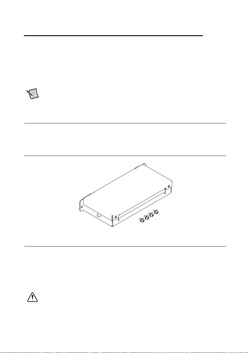
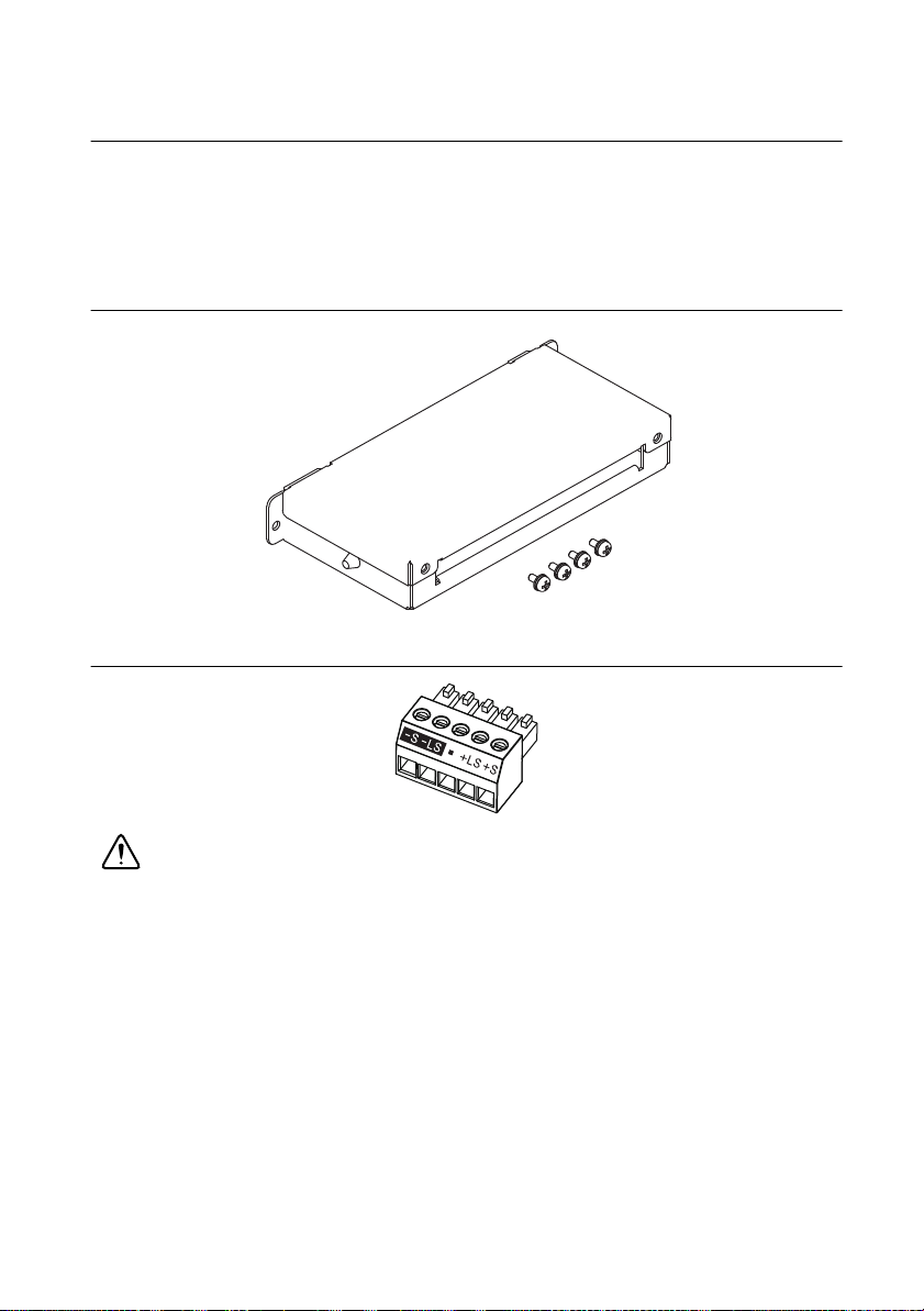
Attaching the Connector Cover
RMX programmable power supplies are supplied with a connector cover that fits over the entire
sensing, J1, and J2 connectors. For safety reasons, be sure to attach the connector cover when
you use the RMX programmable power supply.
Figure 1-1. Connector Cover
Connecting the Power Cord
This product is a piece of equipment that conforms to IEC Overvoltage Category II (equipment
that consumes energy supplied from a fixed installation).
A power cord is not included with the RMX-4124/4125/4126/4127. Use a power cord that
conforms to this product’s rated AC input voltage, input current, and configured for the
plug type. Refer to your product specifications for details.
Caution Risk of electric shock. This product is a piece of equipment that conforms
to IEC Safety Class I (equipment that has a protective conductor terminal). Be sure
to earth ground the product to prevent electric shock. The product is grounded
through the power cord ground wire. Connect the protective conductor terminal to
earth ground.
© National Instruments | 1-1
Page 10

Chapter 1 Installation and Preparation
RMX-4120/4121/4122/4123 (750 W Models)
Necessary Cable
• North America—Extra Hard Usage Cord, min. 300 V, 60 C, 14 AWG, 3 Conductor cord,
3 m or less, with a NEMA 5-15P to C14.
• Europe—HAR Marked, min. 300 V, 60 C, 2.5mm2, 3 Conductor cord, 3 m or less, with a
plug configured for the country of use to C14.
• International—Certified for country of use, min. 300 V, 60 C, 2.5mm
3 m or less, with a plug configured for the country of use to C14.
The power cord can be used to disconnect the RMX programmable power supply from the
AC power line in an emergency. Connect the plug to an easily accessible power outlet so that the
plug can be removed from the outlet at any time. Be sure to provide adequate clearance around
the power outlet.
1. Check that the AC power line meets the nominal input rating of the product. The product
can receive a nominal line voltage in the range of 100 VAC to 240 VAC at 50 Hz or 60 Hz.
2. Check that the POWER switch is turned off.
3. Connect the power cord to the AC inlet on the rear panel.
4. Insert the power plug into a grounded outlet.
2
, 3 Conductor cord,
RMX-4124/4125/4126/4127 (1500 W Models)
Caution Risk of electric shock. Before you connect the power cord, turn off the
switchboard breaker (a switch that cuts off the power supply from the switchboard).
Risk of fire. Connection to the switchboard must be performed by a person who has
knowledge about electrical safety standards and the electrical aspects of regulated
DC power supplies. The switchboard breaker must meet the requirements shown
below.
Caution Inside the product, protective circuits are connected to match the polarity
of the input terminal. Be sure to connect the L, N, and (GND) terminals of the product
to the matching terminals on the switchboard.
In an emergency, turn off the switchboard breaker to disconnect the product from the AC power line.
1-2 | ni.com
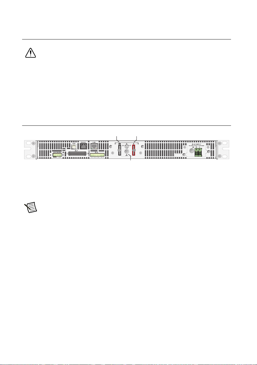
Page 11
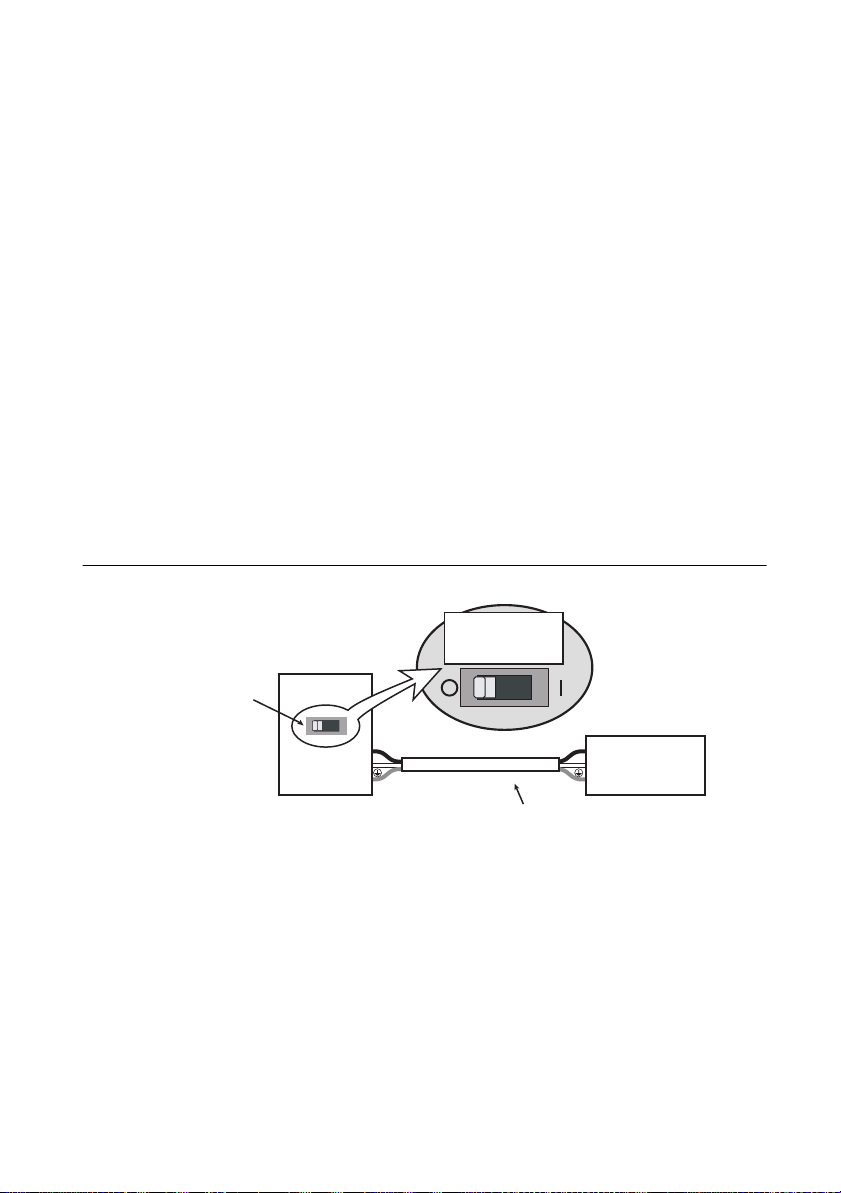
RMX Programmable Power Supplies User Manual
RMX-4125
Switchboard
N
L
N
L
Breaker indication example
For the
RMX-4125 only
30 A
Power cord
RMX-4125
dedicated breaker
Necessary Cable
• Vinyl cabtire cable (VCTF): Nominal cross-sectional area 5.5 mm2, 3 core
• Finished diameter: 10.5 to 14.4 mm in diameter
• Rated voltage: 250 V or higher
• Input terminal end: 14 mm of insulation stripped from conductor for the L and N wires.
Crimping terminal: (round, M4) that fixes the cable insulation in place
for the GND wire
• Length: 3 m or less
Switchboard Breaker Requirements
• Installation must be done in accordance with national wiring rules, such as NFPA 70 "NEC"
and CSA C22.1 "CEC".
• Rated current: 30 A (for safety, breakers whose rated current exceeds 30 A cannot be used)
• Do not power any other equipment from the switchboard breaker.
• Keep the breaker readily accessible at all times.
• Indicate that the breaker is dedicated for use with this product and that it is used to
disconnect the product from the AC power line.
Figure 1-2. Switchboard Diagram
© National Instruments | 1-3
Page 12
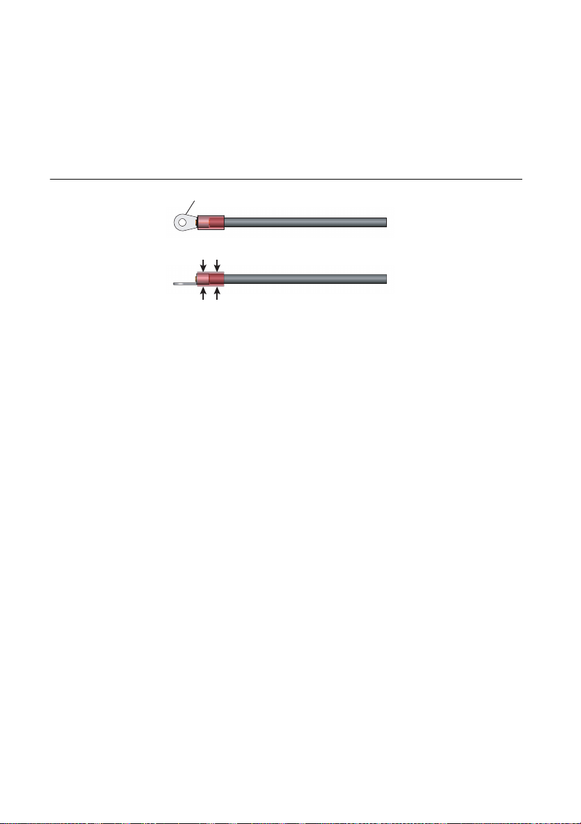
Chapter 1 Installation and Preparation
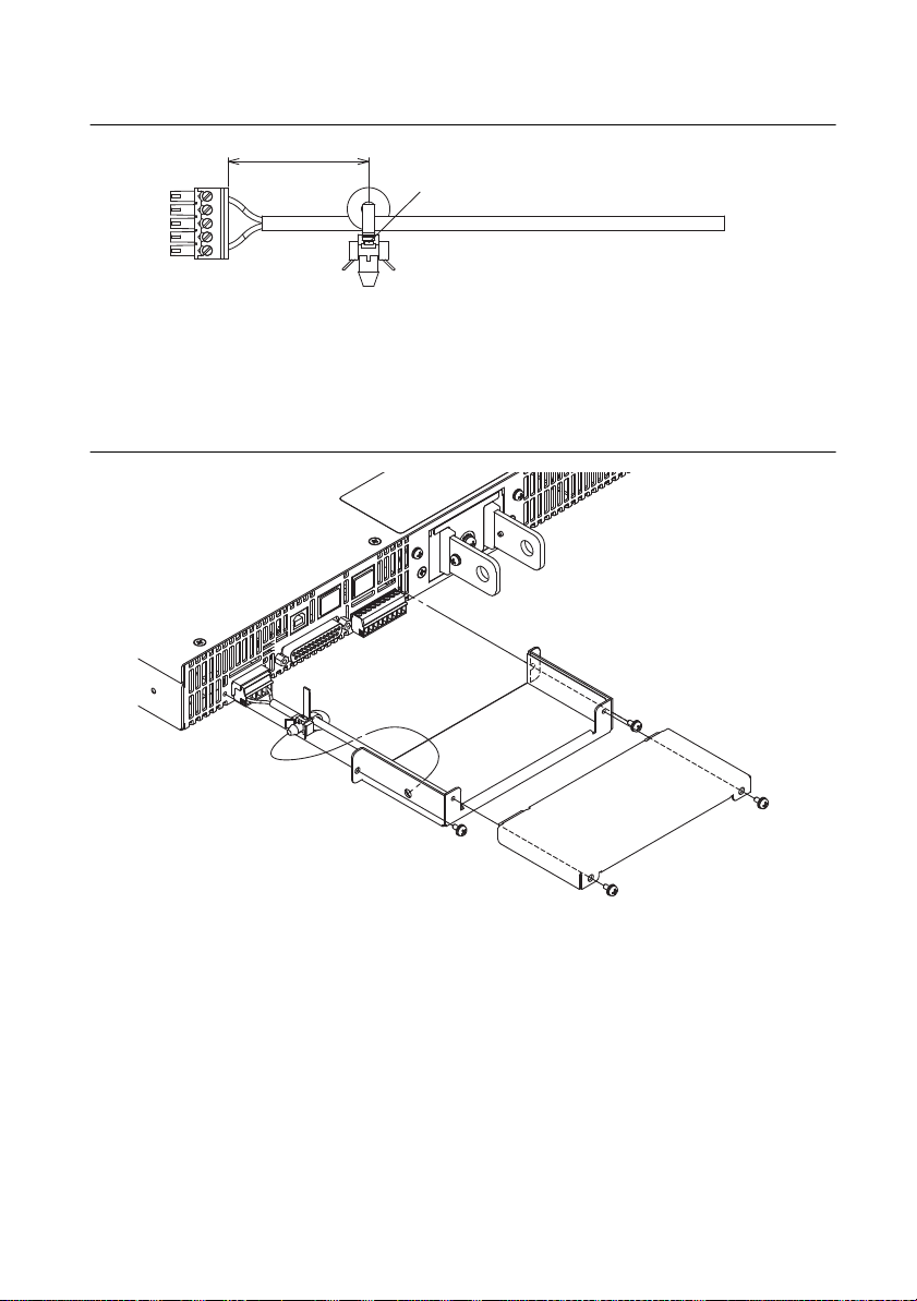
Crimping terminal (round, M4)
When crimping the core wire, use a
crimping terminal and tool that can
also grip the insulation.
Connection Procedure
1. Check that the AC power line meets the nominal input rating of the product. The product
can receive a nominal line voltage in the range of 100 VAC to 240 VAC at 50 Hz or 60 Hz.
2. Check that the POWER switch is turned off.
3. Attach a crimping terminal to the GND wire.
Figure 1-3. Attaching the Crimping Terminal
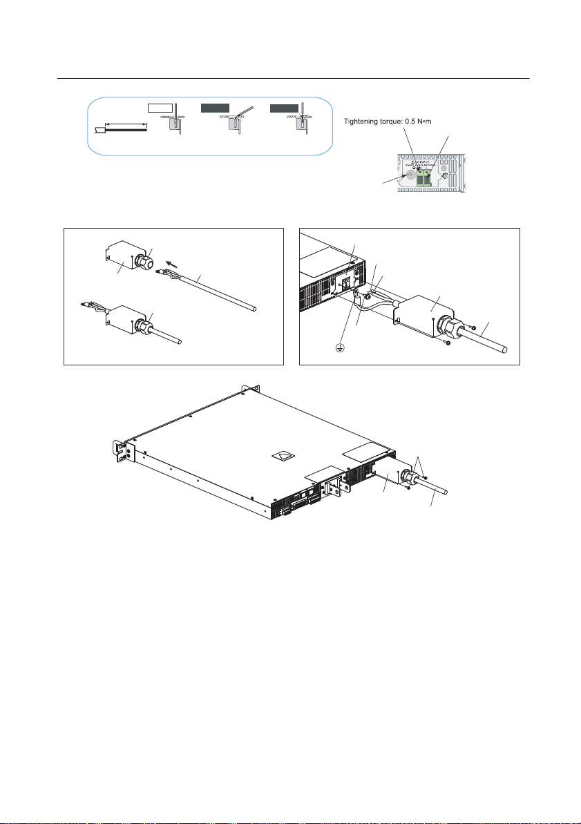
4. Connect the power cord and the included INPUT terminal cover to the AC INPUT terminal
on the rear panel. Be sure to connect the AC INPUT L, N, and (GND) terminals correctly.
Pass the power cord through the INPUT terminal cover, and fix the cord in place using the
cable gland.
1-4 | ni.com
Page 13
RMX Programmable Power Supplies User Manual
STRIP-GAUGE
14 mm
Correct
Incorrect
Incorrect
The stripped wire is
touching the chassis.
The wire strands are
touching the chassis.
INPUT terminal cover
INPUT terminal cover
INPUT terminal cover
AC INPUT terminal
L: Black or brown
N: White or blue
(GND)
Screw
: Green or green and yellow
Power cord
Power cord
Power cord
Screw
Use this screw to fix the
wire in place.
Screw M4
Remove the first
14 mm of the wire’s
covering, and then
insert the wire here.
AC INPUT terminal
Cable gland:
Turn left to unlock
Cable gland:
Turn right to lock
Cable gland: Supports wires from 10.5 to 14.4 mm in diameter
Figure 1-4. Connecting the Power Cord
5. Attach an appropriate crimping terminal to the switchboard end of the power cord.
6. Turn off the switchboard breaker.
7. Connect the L, N, and (GND) wires of the power cord to the matching terminals on the
switchboard.
© National Instruments | 1-5
Page 14

Chapter 1 Installation and Preparation
Turning the Power On
Turning the POWER Switch On
Caution Risk of electric shock. Regardless of whether load cables are connected to
the output terminals, be sure to attach the OUTPUT terminal cover before turning the
POWER switch on.
You can use the CONFIG settings to set how the RMX programmable power supplies
start when you turn the POWER switch on. Depending on the setting, the output may
be turned on automatically when the POWER switch is turned on. If you connect a
load without setting OVP and OCP to appropriate values, the load may be damaged
if the output is programmed to automatically turn on when the power is switched on.
When you turn the POWER switch on for the first time after purchase, the RMX programmable
power supply will be programmed with its factory default settings. Refer to Chapter 2, Factory
Default Settings (Initialization), for more information about these settings. Each subsequent
time you turn the power supply on, it starts with the panel settings (excluding the output on/off
setting) that were in use immediately before the POWER switch was turned off.
You can use the CONFIG setting CF02 to select how the RMX programmable power supply
starts when the POWER switch is turned on. Refer to Chapter 2, CF02 Power-on Status
Parameter, for more information about this setting.
1. Check that the power cord is connected correctly.
2. Check that the OUTPUT terminal cover is attached. Refer to the Attaching the Output
Terminal Cover section for more information about attaching the terminal cover. When the
product is shipped from the factory, the OUTPUT terminal cover is not attached.
3. Turn the POWER switch on. All the LEDs light, and then the voltmeter and the ammeter
display the following sequence of information: the rated voltage and rated current, the
firmware version number, the build number, and then the selected interface. Each item is
displayed for approximately 1 second. After a few seconds, the RMX programmable power
supply enters the operation standby state during which the output value is displayed.
1-6 | ni.com
Page 15

RMX Programmable Power Supplies User Manual
Figure 1-5. Power On Information Display
Inrush Current
When the POWER switch is turned on, an inrush current of up to 70 A can momentarily flow
into the rear AC input of the programmable power supply. Check that sufficient current capacity
is available in the AC power line or the switchboard, particularly if you are using multiple RMX
programmable power supplies and turning on their POWER switches simultaneously.
Turning the POWER Switch Off
Flip the POWER switch to the side to turn RMX programmable power supplies off. The RMX
programmable power supplies save the panel settings (except the output on/off setting) that were
in use immediately before the POWER switch was turned off.
You can use CONFIG settings CF02 to select how the RMX programmable power supply starts
when the POWER switch is turned on. Refer to Chapter 2, CF02 Power-on Status Parameter,
for more information about this setting.
If the POWER switch is turned off immediately after the settings have been changed, the last
settings may not be stored.
Caution After you turn the POWER switch off, wait at least 10 seconds after the
panel display turns off before you turn the POWER switch back on. Repeatedly
turning the POWER switch on and off at short intervals can cause damage to the
inrush current limiter. Furthermore, this will shorten the service life of the POWER
switch and the internal input fuse.
© National Instruments | 1-7
Page 16
Chapter 1 Installation and Preparation
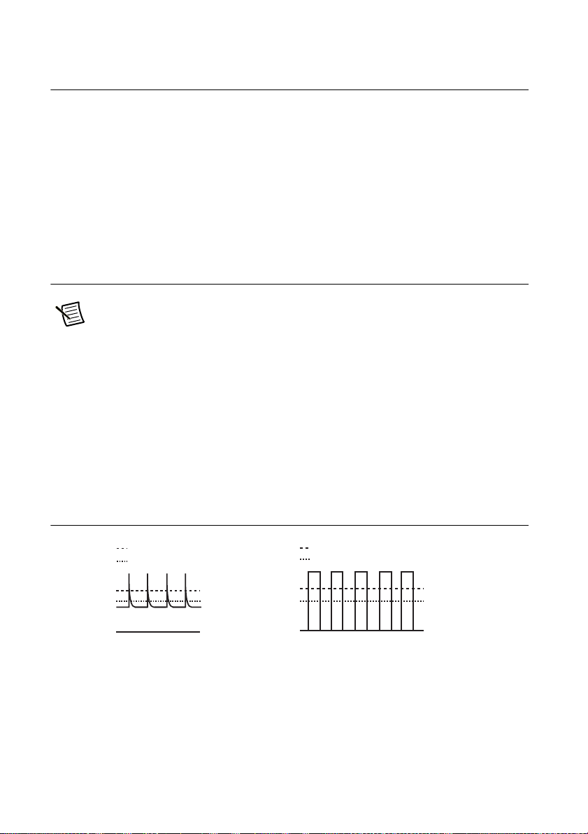
Load current with peaks Pulse-shaped load current
Set constant current
Ammeter reading (mean value)
Set constant current
Ammeter reading (mean value)
Rack Mounting
You can use brackets or slide rails to mount the RMX programmable power supply to a rack.
When you mount an RMX programmable power supply to a rack, install the optional support
angles (NI P/N) to support the device.
NI recommends that you keep all pieces that you remove from a RMX programmable power
supply during installation. You will need these pieces if you remove the device from a rack.
When using several RMX programmable power supplies together for master-slave parallel or
series operation, mount them to a rack before use.
Load Considerations
Note The output can become unstable if the following types of loads are connected.
Loads with Peak Current or Pulse-Shaped Current
The front panel of the RMX power supply only displays averaged voltage and current values.
If the supply is connected to a load that draws current in spikes or pulses it is possible that the
front panel will display a current reading lower than the programmed current setpoint. In reality,
the spikes or pulses in the load current are exceeding the programmed current setpoint causing
the supply to switch instantaneously into constant-current mode and causing the output voltage
to drop.
For these types of loads, you must increase the set constant current or increase the current
capacity.
Figure 1-6. Loads with Peak Current or Pulse-Shaped Current
1-8 | ni.com
Page 17
RMX Programmable Power Supplies User Manual
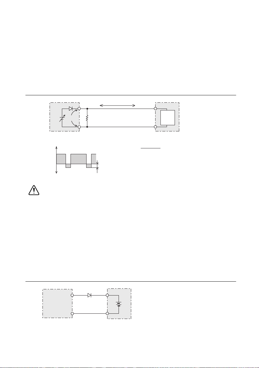
IO
RD
EO
Equivalent circuit of the RMX-4122
Regenerative load
+
0
Reverse current
-IO
+IO
Irp
RD (in Ω) ≤
RD: Reverse current bypass dummy load
E
O: Output voltage
Irp: Maximum reverse current
EO (in V)
Irp (in A)
Load
Output current
Loads that Generate Reverse Current to the Power Supply
RMX programmable power supplies cannot sink reverse current from the load. Therefore, if a
regenerative load (such as an inverter, converter, or transformer) is connected and tries to sink
power into the terminals of the power supply, the output voltage will increase and can become
unstable. This can cause a malfunction.
For these types of loads, connect a resistor (R
) as shown in the following figure to bypass the
D
reverse current. However, the amount of current to the load decreases by Irp.
Figure 1-7. Loads with Accumulated Energy
Caution Use a resistor with sufficient rated power for R
. If a resistor with
D
insufficient rated power for the circuit is used, the resistor will burn out.
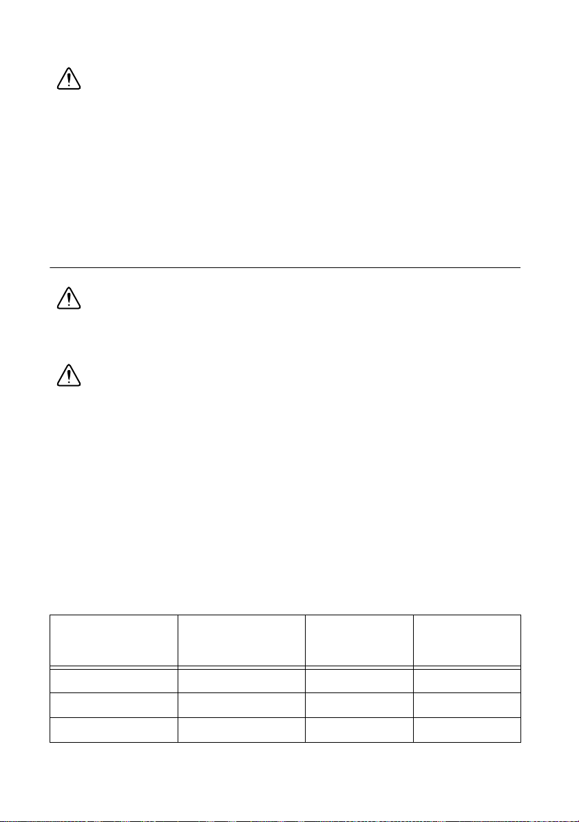
Loads with Accumulated Energy
Connecting a load with accumulated energy, such as a battery, to an RMX programmable power
supply may cause current to flow from the load to the internal circuit. This current may cause
damage or reduce the life of the load.
For this type of load, connect a reverse-current-prevention diode (D
programmable power supply and the load in series as shown in the following figure.
) between the RMX
RP
This cannot be used in conjunction with remote sensing.
RMX-4122
Figure 1-8. Loads with Accumulated Energy
D
RP
Load with accumulated energy
DRP: Reverse-current-protection diode
© National Instruments | 1-9
Page 18
Chapter 1 Installation and Preparation
Caution To protect the load and the RMX programmable power supplies, use a D
RP
that conforms to the following specifications.
• Reverse voltage withstand capacity–At least twice the rated output voltage of the RMX
programmable power supply.
• Forward current capacity–Three to ten times the rated output current of the RMX
programmable power supply.
• A diode with small loss.
• Be sure to take into account the heat generated by D
. DRP will burn out with inadequate
RP
heat dissipation.
Load Cables
Caution Risk of fire. Use load cables whose capacity is adequate for the
RMX programmable power supply’s rated output current. The output connector and
its surrounding area become hot. Use cables whose covers have heat resistance at
85 °C and higher.
Caution Risk of electric shock. Use the cable which has higher withstanding
voltage than the specified insulation voltage of the product to secure the double
insulation or reinforced insulation.
The current capacity of a load cable is dependent on the maximum allowable temperature of the
cable's insulation.
A cable’s temperature is determined by the resistive loss based on the current, the ambient
temperature, and the cable’s external thermal resistance. The following table shows the current
capacity of heat-resistant vinyl wires that have a maximum allowable temperature of 60 °C,
assuming that a wire is stretched out horizontally in air in an ambient temperature of 30 °C.
The current capacity must be reduced under certain conditions, such as when vinyl cables that
have a low heat resistance are used, when the ambient temperature is 30 °C or greater, or when
cables are bundled together and little heat is radiated.
Table 1-1. Current Capacity of Heat-resistant Vinyl Wires
Nominal
Cross-sectional
Area
2 mm
3.5 mm
5.5 mm
1-10 | ni.com
2
2
2
AWG (Reference
Cross-sectional
Area)
Allowable
Current
(Ta = 30 °C)
Recommended
Current
14 (2.08 mm2) 27 A 10 A
12 (3.31 mm2) 37 A —
10 (5.26 mm2) 49 A 20 A
Page 19

RMX Programmable Power Supplies User Manual
Table 1-1. Current Capacity of Heat-resistant Vinyl Wires (Continued)
Nominal
Cross-sectional
Area
2
8 mm
2
14 mm
2
22 mm
2
30 mm
2
38 mm
2
50 mm
2
60 mm
2
80 mm
2
100 mm
2
125 mm
2
150 mm
2
200 mm
AWG (Reference
Cross-sectional
Area)
Allowable
Current
(Ta = 30 °C)
Recommended
Current
8 (8.37mm2) 61 A 30 A
6 (13.3 mm2) 88 A 50 A
4 (21.15 mm2) 115 A 80 A
2 (33.62 mm2) 139 A —
1 (42.41 mm2) 162 A 100 A
1/0 (53.49 mm2) 190 A —
2/0 (67.43 mm2) 217 A —
3/0 (85.01 mm2) 257 A 200 A
4/0 (107.2 mm2) 298 A —
— 344 A —
— 395 A 300 A
— 469 A —
Protecting Against Noise
When connecting wires that have the same heat resistance, separating the wires as much as
possible to increase heat radiation enables a greater amount of current to flow. However, wiring
the + (positive) and - (negative) output wires of the load cable side by side or bundling them
together will minimize unwanted noise on the output. The currents shown in Table 1-1 are
allowable currents that have been reduced in consideration of the potential bundling of load
cables. Use these values as a guideline when connecting load cables.
Cabling Considerations When Using Remote Sensing
As you increase the current setpoint or increase the resistance of your load cabling, the voltage
drop between the RMX power supply and your load will increase. This results in the voltage at
your load being smaller than the programmed voltage setpoint. Refer to Appendix A,
Specifications, to see the maximum voltage drop each RMX power supply's remote sense
terminals can compensate for. If the voltage drop exceeds this level, use shorter load cables or
cables with a greater cross-sectional area.
© National Instruments | 1-11
Page 20
Chapter 1 Installation and Preparation
- (negative) terminal + (positive) terminal
Chassis terminal
Connecting to the Output Terminals
Caution Risk of electric shock. Turn the POWER switch off before you touch the
OUTPUT terminals. Even if you turn the output off or turn the POWER switch off,
if the bleeder on/off setting (CF11) is set to “OFF,” the voltage that was present when
the output was on will remain at the output terminals. Turn the bleeder circuit on
before you touch the output terminals. Regardless of whether load cables are
connected to the output terminals, be sure to attach the OUTPUT terminal cover
before turning the POWER switch on. Confirm that the voltage between any output
terminal and ground is lower than the isolation voltage of the RMX programmable
power supply.
Figure 1-9. RMX-4125 Output Terminal
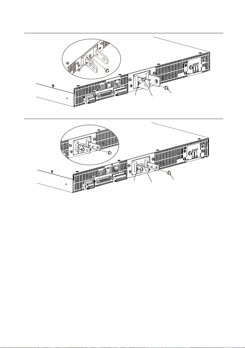
1. Turn the POWER switch off. Check that there is no voltage across the output terminals.
2. Connect one end of the included chassis connection wire to the chassis terminal, and then
connect the other end of the wire to the negative or positive output terminal.
Note For safety reasons, connect one of the output terminals to the chassis terminal
unless your application requires the output terminals to be floating.
Use the screw on the RMX to connect the wire to the chassis terminal. Use the screw on the
output terminal to connect the wire to the output terminal.
1-12 | ni.com
Page 21
RMX Programmable Power Supplies User Manual
Chassis
connection wire
Screw (M3)
Screw (M4)
Chassis
connection wire
Screw (M3)
Screw (M4)
Figure 1-10. RMX-4120/4121/4124/4125
Figure 1-11. RMX-4122/4123/4126/4127
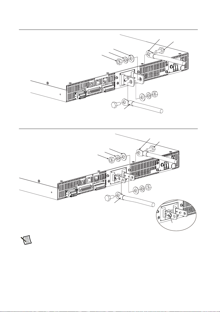
3. Attach crimping terminals to the load cables.
The output terminals have holes for connecting the load cables. Use crimping terminals that
are appropriate for the bolts that you are using.
4. Use the included bolt set to connect the load cables to the output terminals.
Connect the positive cable to the positive output terminal and the negative cable to the
negative output terminal. The orientation of the crimping terminals will vary depending on
the wire diameter of the load cables used.
© National Instruments | 1-13
Page 22
Chapter 1 Installation and Preparation
Spring washer
Washer
Nut
Bolt (M8)
Crimping terminal
Attach the cable to the inner side
of the crimping terminal.
Attach the cable to the outer side
of the crimping terminal.
Spring washer
Washer
Nut
Bolt (M5)
Screw (M4)
Figure 1-12. Connection Using M8 Bolt Set for RMX-4120/4121/4124/4125
Figure 1-13. Connection Using M5 Bolt Set for RMX-4122/4123/4126/4127
Crimping terminal
Note If you do not connect load cables in the correct orientation, you will not be
able to attach the OUTPUT terminal cover.
1-14 | ni.com
Page 23
RMX Programmable Power Supplies User Manual
R
line up the half of the cover.
Attaching the Output Terminal Cover
You can adjust the diameter of the holes that the load cables pass through by changing the
positions in which the top and bottom halves of the OUTPUT terminal cover are put together.
There are two available positions. Use the appropriate position for the load cables that you are using.
• For cables that are up to 10 mm in diameter: Put the top and bottom halves of the OUTPUT
terminal cover together so that the hole diameter is small.
• For cables that are between 10 mm and 18 mm in diameter: Put the top and bottom halves
of the OUTPUT terminal cover together so that the hole diameter is large.
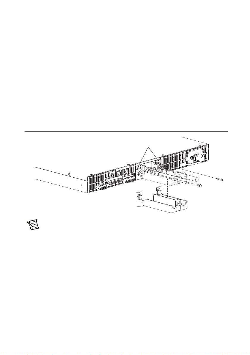
1. Remove the screw that is attached next to the output terminals on the RMX. Use this screw
to attach the OUTPUT terminal cover.
2. Place the bottom half of the OUTPUT terminal cover underneath the load cables connected
to the output terminals.
Figure 1-14. Attaching Bottom Half of the OUTPUT Terminal Cover
emove the screws, and then
Note The top and bottom halves of the OUTPUT terminal cover have different
shapes.
3. Align the tabs of the top half of the OUTPUT terminal cover with those of the bottom half.
Align the tabs of the OUTPUT terminal cover according to the load cable diameter.
© National Instruments | 1-15
Page 24
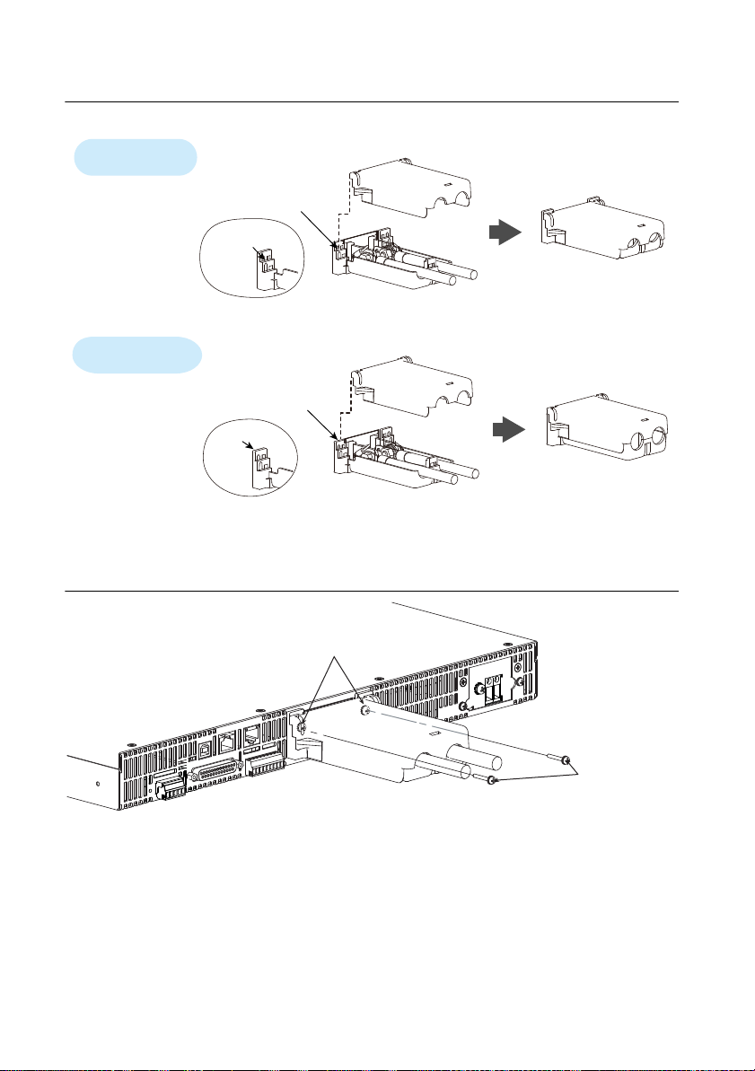
Chapter 1 Installation and Preparation
Top half of the cove
Align the protrusion of
the top half of the cover
with the top section
of the protrusion of the
bottom half.
Bottom half of the cover
For thick load cables
Cover hole diameter:
10 mm to 18 mm
Cover hole diameter:
Up to 10 mm
For thin load cables
Top half of the cover
Align the protrusion of
the top half of the cover
with the middle section
of the protrusion of the
bottom half of the cover.
Bottom half of the cover
Middle
section
Top section
After you have lined up the top and bottom halves
of the cover, use the screws to fix the cover in place.
Screws (M3)
Figure 1-15. Aligning Both Halves of the OUTPUT Terminal Cover
4. Push the OUTPUT terminal cover against the rear panel, and then use the RMX screws to
fix the cover in place. Ensure that the screws are securely fastened.
Figure 1-16. Attaching the OUTPUT Terminal Cover
1-16 | ni.com
Page 25
RMX Programmable Power Supplies User Manual
Sensing
When RMX programmable power supplies are shipped from the factory, the connector is
attached to the sensing terminals. RMX programmable power supplies are supplied with a
connector cover that fits over the entire sensing, J1, and J2 connectors. For safety reasons,
be sure to attach the connector cover when you use the RMX programmable power supply.
If they are damaged or lost, contact National Instruments.
Figure 1-17. Connector Cover
Figure 1-18. Terminal Connector
Caution Risk of electric shock and damage to internal circuits.
Never wire the sensing terminals while the POWER switch is turned on.
Use sensing cables that provide reinforced or double insulation with a capacity
greater than or equal to the isolation voltage of the RMX programmable power
supply. For uncovered sections of the shielded cables, use insulation tubes to secure
reinforced or double insulation with a capacity greater than or equal to the isolation
voltage of the RMX programmable power supply.
The sensing terminals are at approximately the same electric potential as the negative
output terminal. Insert the cables so that the wire strands do not touch the chassis
when they stick out of the sensing terminal. Also, insert the cables so that the stripped
wires do not stick out of the terminal.
© National Instruments | 1-17
Page 26
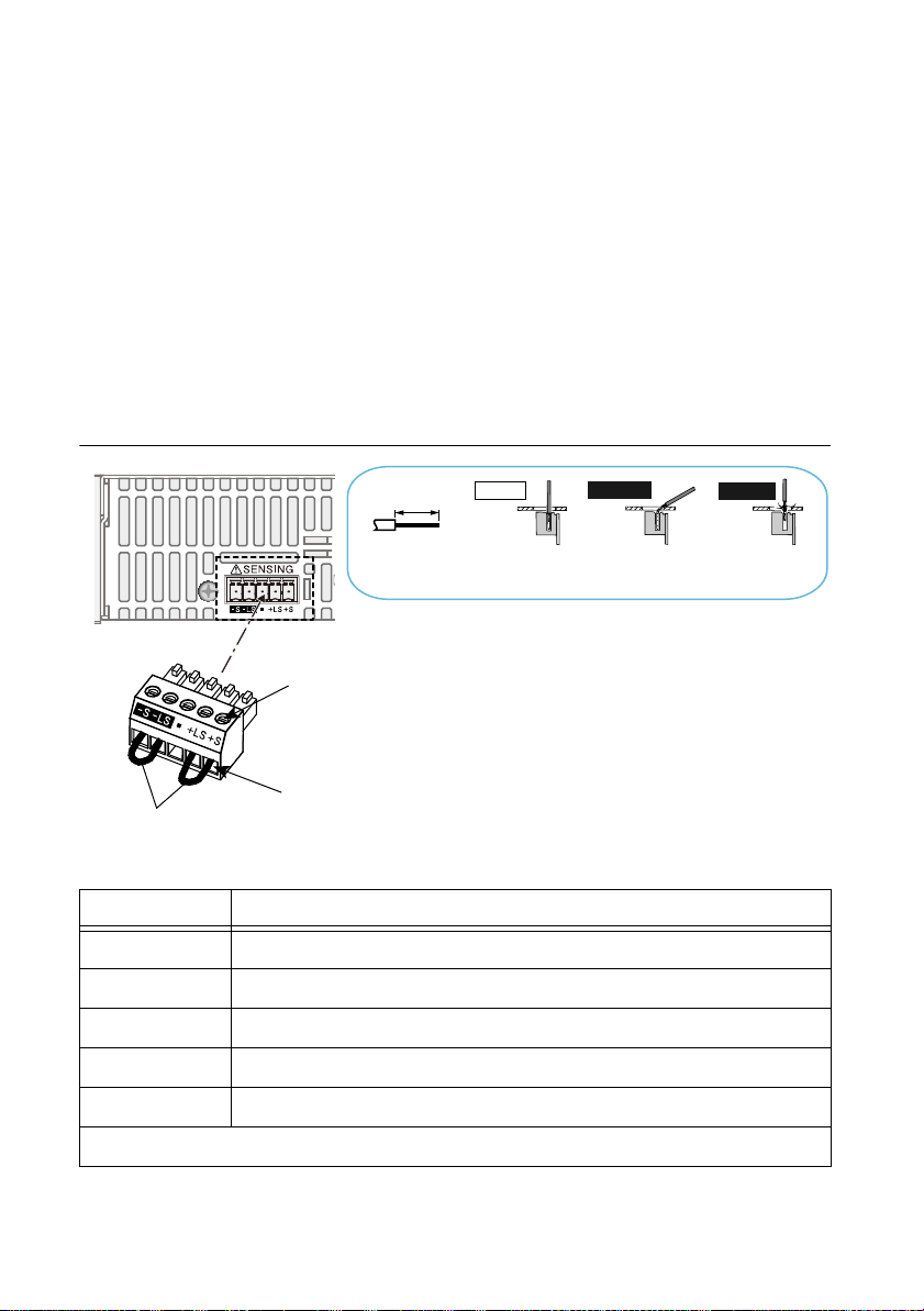
Chapter 1 Installation and Preparation
Strip 7 mm (0.28 inches) of the
cable covering, and then insert
the cable here.
Incorrect
Incorrect
Correct
The wire itself is
in contact with
the chassis.
Wire scraps are
in contact with
the chassis.
Strip gauge
7 mm (0.28 inches)
Use this screw to fix the cables
cables in place so that they do
not come loose.
Local sensing jumpers
Even if you turn the output off or turn the POWER switch off, if the bleeder on/off
setting (CF11) is set to oFF, the voltage that was present when the output was on will
remain at the output terminals. Set the bleeder on/off setting to on before you touch
the sensing terminals.
Regardless of whether local sensing or remote sensing is used, be sure to attach the
sensing terminal cover before turning the POWER switch on.
If the sensing cables come loose, the output voltage across the load may become unstable, and
an excessive voltage may be applied to the load. If an appropriate OVP trip point is set, the OVP
will trip before an excessive voltage is generated.
When you are finished with remote sensing, return to local sensing mode.
Figure 1-19. Sensing Cable Connections
Terminal Function
-S Negative remote sensing terminal.
-LS Negative local sensing terminal connected to the negative output terminal
— Not connected.
+LS Positive local sensing terminal connected to the positive output terminal.
+S Positive remote sensing terminal.
Sensing cable: AWG28 to AWG16
1-18 | ni.com
Table 1-2. Sensing Terminals and Functions
Page 27
RMX Programmable Power Supplies User Manual
+
–
+LS
+S
-LS
-S
Output terminal
Chassis terminal
Sensing terminal
RMX
Load
Use twisted-pair wires for the load cables.
Make the cables as short as possible.
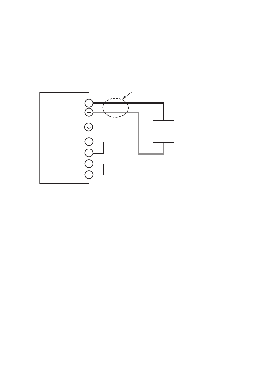
Local Sensing
By factory default, RMX programmable power supplies are set to local sensing (the rear panel
sensing connector is hard wired). The sensing point during local sensing is the output terminal.
This method does not compensate for the voltage drop across the load cable, so use this method
when the load current is small or when you do not need to consider the load effect voltage.
Figure 1-20. Local Sensing
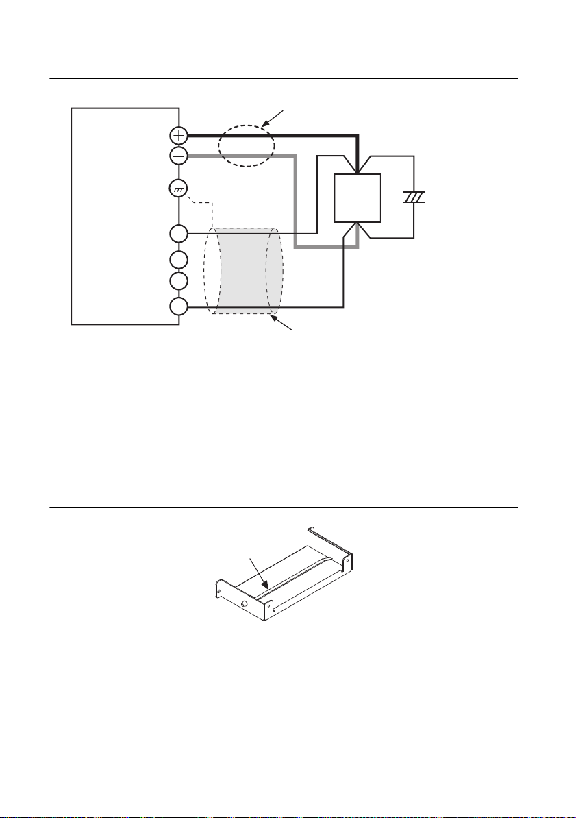
Remote Sensing
Remote sensing is a feature that reduces the effect of voltage drops across load cabling
resulting in a more accurate voltage being applied at the terminals of the load.
Refer to Appendix A, Specifications for the maximum voltage drop each RMX power supply's
remote sense terminals can compensate for. Select a load cable that has sufficient current
capacity to prevent the voltage drop in the load cable from exceeding the compensation voltage.
Refer to the Load Cables section for more information about the cables.
When using remote sensing, the output terminals compensate for the voltage drop across the load
cabling by increasing the output voltage above the programmed setpoint until the sense leads
detect the programmed setpoint at the load itself. This requires the output terminals to generate
a voltage that is greater than the programmed voltage level. If you are performing remote sensing
with the voltage close to the maximum output voltage of the power supply, the total output is
still limited by the maximum output voltage at the terminals of the power supply (105% of the
rated output voltage). If the signal doesn’t seem to be stable, an electrolytic capacitor may be
required at the sensing point (across the load).
To minimize noise on the output signal, use twisted-pair wires or 2-core shielded wires. Connect
the ground of your shielded wire to the ground of the RMX programmable power supply or the
load.
© National Instruments | 1-19
Page 28
Chapter 1 Installation and Preparation
Band
Figure 1-21. Remote Sensing
RMX
Output terminal
Chassis terminal
Sensing terminal
+S
+LS
-LS
-S
Use twisted-pair wires for the load cables.
Make the cables as short as possible.
+
+
Load
–
For the sensing cables, use twisted-pair
wires or shielded wires.
C
–
Connect an
electrolytic
capacitor
across the load
as necessary.
1. Turn the POWER switch off.
2. Remove the sensing connector from the rear panel sensing terminals.
3. Remove the local sensing jumpers from the sensing connector.
4. Remove 7 mm of the wire covering. Connect the negative sensing cable to -S and the
positive sensing cable to +S.
Use cable screws to securely fix the cables in place so that they do not come loose.
5. Pinch the tip of the band, and remove the band from the connector cover.
Figure 1-22. Bottom Cover with Band
6. As shown in the figure, create a ring 40 mm away from the connector, and fasten with the band.
Make the ring as small as possible, and fasten the band as tight as possible. The band can
be reused. Do not cut the extraneous portion of the band.
1-20 | ni.com
Page 29
RMX Programmable Power Supplies User Manual
through the hole by holding this area with
a pair of tweezers.
Figure 1-23. Sensing Wire Assembly
40 mm
You can pull out the band that you passed
7. Firmly attach the sensing connector to the sensing terminals.
8. Fasten the lower side of the connector cover to the panel with the included screws, and then
insert the tip of the band into the hole of the cover. Finally, bring the top and bottom sides
of the connector cover together, and fasten with the included screws.
Figure 1-24. Connector Cover Assembly
9. Turn the power switch on.
© National Instruments | 1-21
Page 30
Chapter 1 Installation and Preparation
Load
S
+
–
C
+
–
+S
–S
+
–
Connecting an Electrolytic Capacitor Across the Load
If the cabling is largely inductive, it may be necessary to connect an electrolytic capacitor across
the load. If you run into this problem, the following symptoms may appear:
• The output of the power supply is oscillating. If very long wires are used to connect the
load, the inductive and capacitive components of the cable can cause phase shifting that
results in oscillation at the output. You can reduce this effect by shortening the load cables.
However, if this does not rectify the problem, connect and electrolytic capacitor across the
load.
• If the load current is changing rapidly in a pulse-shaped pattern, the output voltage may
fluctuate due to inductance in the cabling. You can reduce the inductance component by
twisting the load cables, which stabilizes the voltage. However, if this does not rectify the
problem, connect an electrolytic capacitor across the load.
Table 1-3. Electrolytic Capacitor with RMX Programmable Power Supplies
RMX-4120
RMX-4124
RMX-4121/
RMX-4125
RMX-4122/
RMX-4126
RMX-4123/
RMX-4127
36 V or more 96 V or more 276 V or more 780 V or more
Capacitance: 0.1 μF to a few hundred μF.
Withstand voltage: At least 120% of the rated output voltage of the RMX programmable
power supply.
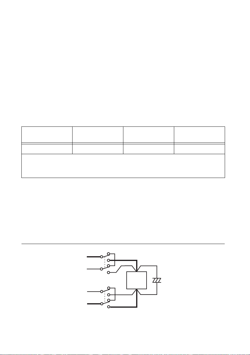
Inserting a Mechanical Switch Between the RMX Programmable Power Supply and the Load
If you want to connect and disconnect the load using a mechanical switch that is inserted
between the RMX programmable power supply and the load, be sure to include switches in the
sensing cables as shown in the following figure. Also make sure to turn on and off the load cable
and sensing cables simultaneously. Before you turn the mechanical switch on or off, be sure to
turn the output or the POWER switch off.
Figure 1-25. Mechanical Switch in a Sensing Cable
1-22 | ni.com
Page 31

RMX Programmable Power Supplies User Manual
Accessories
RMX programmable power supplies have the following available accessories. For more
information about accessories contact National Instruments.
Parallel Operation Signal Cable
This cable is used when you perform parallel operations. The following three types are available:
Part Number Description
784821-01 Cable Assembly, RMX-412x Parallel Operation (2 units)
784822-01 Cable Assembly, RMX-412x Parallel Operation (3 units)
784823-01 Cable Assembly, RMX-412x Parallel Operation (4 units)
Figure 1-26. Parallel Operation Signal Cable
© National Instruments | 1-23
Page 32

2
Lit
Basic Functions
This chapter describes how to turn the output on and off and the basic operations that you can
perform from the front panel.
Measured Value Display and Setting Display
The voltage and current displays have the following two states:
• Measured value display
• Setting display
Measured Value Display
When the SET key LED is off, the front panel will display the measured value of the voltage and
current at the output terminals. You can still change the output voltage and current settings while
in this state, but the front panel will continue to display the values measured at the output. Refer
to the Using the RMX Programmable Power Supplies as a CV or CC Power Supply section for
more information about these functions.
Figure 2-1. Measured Value Display
Power Display
While in the measured value display, press PWR DSPL to display the output power on the
ammeter.
The output power is calculated from the measured output voltage and the measured output current.
When displaying the output power, the PWR DSPL key LED will light up. Press PWR DSPL
again to return to measured value display.
Figure 2-2. Power Display
© National Instruments | 2-1
Page 33

Chapter 2 Basic Functions
Lit
Lit
Setting Display
Press SET to display the present output voltage and output current settings, which will cause the
SET key LED to illuminate. Press SET again to return to the measured value display.
Figure 2-3. Setting Display
When you recall a preset memory entry, the values stored in the preset memory entry are
displayed on the panel.
Overvoltage Protection and Overcurrent Protection Setting Display
Press OCP•OVP to light its LED and display the present overcurrent protection and overvoltage
protection settings.
Figure 2-4. OCP and OVP Display
System Configuration Setting Display
Press CONFIG to light its LED and display the present system configuration settings. Refer to
the CONFIG Settings section for detailed information about these settings.
Figure 2-5. System Configuration Setting Display
Lit
2-2 | ni.com
Page 34

RMX Programmable Power Supplies User Manual
Decrease IncreaseIncrease Decrease
Panel Operations
Measured Value Display, Setting Display, and Set OVP/OCP Display
Turn the VOLTAGE knob to change the voltage. Turn the CURRENT knob to change the
current.
Figure 2-6. Panel Operations
While in setting display mode (the SET key LED is illuminated), turning the VOLTAGE and
CURRENT knobs will update the output voltage and current settings.
You cannot set the output voltage to a value that is 95% of the OVP trip point or higher. You
cannot set the output current to a value that is 95% of the OCP trip point or higher.
The displayed current or voltage may not change when you turn the CURRENT or VOLTAGE
knob. This is because the values are being changed at a finer resolution than the front panel can
display. The display will update when the amount that you change the value by reaches the
smallest display digit of the set voltage or current.
Fine Adjustment
Holding down the SHIFT key while turning the VOLTAGE or CURRENT knobs allows for
finer adjustment of the programmed voltage and current values.
Note When you set a value, it is convenient to first use normal resolution to set the
value roughly and then switch to fine resolution to set it precisely.
Output Operations
The toggles each time you press OUTPUT. When output is on, the OUTPUT LED in the display
area lights. When the output is off, the OUTPUT LED in the display area turns off.
When the OUTPUT key LED is on, the power supply will drive its output terminals to a level
determined by the voltage and current settings. If you change the settings while the output is on,
the changes are applied immediately to the output. If you change the settings while the output is
off, the device will switch to setting display mode (the SET key LED will light up). Pressing
OUTPUT will apply and drive the output terminals using the new settings.
© National Instruments | 2-3
Page 35

Chapter 2 Basic Functions
Lit
You can use external control to toggle the output as well. Refer to Chapter 3, External Control,
for additional information. CONFIG setting CF12 can be used to program the device to prioritize
CC or CV mode at startup.
Figure 2-7. Output Operations
Output State at Power-up
In the factory default settings, the output is off when the RMX programmable power supply
turns on. Using CONFIG parameter CF02, you can set the RMX programmable power supply
so that output is turned on at power on.
If you set the RMX programmable power supply so that output is turned on at power on, be sure
to check that the OVP trip point is set appropriately before you turn the RMX programmable
power supply off.
Caution If you change the load, it may be damaged if the RMX programmable
power supply OVP and OCP settings are not correct.
Operation Overview
The RMX programmable power supply is a constant voltage (CV)/constant current (CC)
regulated DC power supply that can output a wide range of voltage and current within rated
output power.
If you configure the settings so that output voltage × output current is less than or equal to the
rated output power, the RMX programmable power supply operates as a traditional
constant-voltage (CV)/constant-current (CC) power supply.
If you configure the settings so that “output voltage × output current” is greater than the rated
output power, the actual output is limited by the power limit (approximately 105% of the rated
output power), and the output voltage and output current change depending on the load value.
2-4 | ni.com
Page 36

RMX Programmable Power Supplies User Manual
35
30
25
20
15
10
5
0
0 20 40 60 80 100 120 140 150 160
Rated output voltage: 30 V
Rated output power
Rated output current
Output voltage (V)
Output current (A)
RMX-4120: 750 W
RMX-4124: 1500 W
Rated output power
01020304050 80
RMX-4120
60 70 75
RMX-4124
90
80
70
60
50
40
30
20
10
0
Output voltage (V)
Rated output voltage: 80 V
Rated output power
Rated output current
RMX-4121: 750 W
RMX-4125: 1500 W
Rated output power
0 5 10 15 20 25 30
0 102030405060
RMX-4121
RMX-4125
Output current (A)
56
28
Figure 2-8. RMX-4120/4124 Output Power
Figure 2-9. RMX-4121/4125 Output Power
© National Instruments | 2-5
Page 37

Chapter 2 Basic Functions
300
250
200
50
150
100
0
024681012
0 4 8 12162024
RMX-4122: 750 W
RMX-4126: 1500 W
Rated output voltage: 230 V
Rated output power
Rated output power
Rated output current
RMX-4122
RMX-4126
Output voltage (V)
Output current (A)
700
600
500
400
300
200
100
0
012345 786
Rated output voltage: 650 V
Rated output power
Rated output current
Output voltage (V)
Output current (A)
RMX-4123: 750 W
RMX-4127: 1500 W
Rated output power
0 0.5 1 1.5 2 2.5 3.5 43
RMX-4123
RMX-4127
Figure 2-10. RMX-4122/4126 Output Power
Figure 2-11. RMX-4123/4127 Output Power
2-6 | ni.com
Page 38

RMX Programmable Power Supplies User Manual
CV Power Supply and CC Power Supply
The RMX programmable power supply can operate in constant-voltage (CV) or constant-current
(CC) mode. The operation mode is determined by the following three values.
• The set output voltage (VS)
• The set output current (I
• The load resistance (RL)
The operation modes are described below.
Figure 2-12. RMX Programmable Power Supplies Operation Modes
)
S
V
ma x
V
S
out
p
A
Output voltage V
0
Output current I
RL > R
B
out
C
q
I
SImax
RL = R
RL < R
C
Crossover point
C
A = CV mode area
B
= CC mode area
= Set voltage
V
S
I
= Set current
S
R
= Vs/Is (Ohm’s Law)
C
= Load resistance
R
L
V
= Maximum settable voltage
max
= Maximum settable current
I
max
The above figure shows the operation modes of an RMX programmable power supply. The load
resistance is denoted as RL. The compliance resistance RC is calculated from the set voltage and
current (RC=VS/IS). The power supply is designed so that it operates in CV mode in area A and
CC mode in area B. The boundary between the two operation modes is the line defined by R
=
L
RC. This line represents the load at which the output voltage equals the set voltage and the output
current equals the set current. If load resistance RL is greater than the compliance resistance RC,
the operating point falls in area A, and the RMX programmable power supply will operate in CV
mode (point p). In this case, the set current I
operates as a current limit.
S
When operating in CV mode, the output voltage is maintained at the programmed voltage
setpoint. The output current I is determined by the equation I = V
and is less than current
S/RL
limit IS. The actual current that flows is determined by the voltage setpoint and the load
resistance and will not necessarily be equal to the programmed value.
For loads which may cause transient current spikes, current I
must be set so that the peak value
S
does not reach the current limit.
Conversely, if load resistance R
is less than the compliance resistance RC, the operating point
L
falls in area B, and the RMX programmable power supply operates in CC mode (point q). In this
case, set voltage V
operates as a voltage limit.
S
© National Instruments | 2-7
Page 39

Chapter 2 Basic Functions
When operating in CC mode, the output current is maintained at the programmed current
setpoint. The output voltage V is determined by the equation V = I
× RL and is less than voltage
S
limit VS. The actual voltage that flows is determined by the current setpoint and the load
resistance and will not necessarily be equal to the programmed value.
For loads that generate transient voltage spikes, V
must be set so that the surge voltage does not
S
reach the voltage limit.
Crossover Point
The RMX programmable power supply switches automatically between CV mode and CC mode
according to the changes in the load. A crossover point is the point at which the mode switches.
For example, when operating in CV mode, if the load changes and the output current reaches the
current limit, the RMX programmable power supply automatically switches to CC mode to
protect the load. Likewise, when operating in CC mode, if the output voltage reaches the voltage
limit, the RMX programmable power supply switches to CV mode.
CV Mode and CC Mode Operation Examples
This section uses a power supply with a rated output voltage of 100 V and a rated output current
of 10 A as an example.
Example 1
A load resistance (RL) of 8 Ω is connected to the output terminals of the power supply. The
output voltage and output current are set to 30 V and 5 A, respectively. In this case,
= 30 V/5 A = 6 Ω. Because 8 Ω is greater than 6 Ω (RL > RC), the power supply operates in
R
C
CV mode. When you want to increase the voltage in CV mode, you can increase the voltage up
to the voltage defined by the following equation: Vs = Is × R
Vs = 5 A × 8 Ω = 40 V. If you try to increase the voltage above this point, the crossover point is
reached, and the power supply automatically switches to CC mode. To maintain operations in
CV mode, increase the current limit.
. Substituting the values, obtains
L
Example 2
Next, a load resistance (RL) of 5 Ω is connected to the output terminals of the power supply.
The output voltage and output current are set to 30 V and 5 A, respectively. In this case,
= 30 V/5 A = 6 Ω. Because 5 Ω is less than 6 Ω (RL < RC), the power supply operates in
R
C
CC mode. When you want to increase the current in CC mode, you can increase the current up
to the current defined by the following equation: I
IS = 30 V/5 Ω = 6 A. If you try to increase the current above this point, the crossover point is
reached, and the power supply automatically switches to CV mode. To maintain operations in
CC mode, increase the voltage limit.
2-8 | ni.com
= VS/RL. Substituting the values, obtains
S
Page 40

RMX Programmable Power Supplies User Manual
Using the RMX Programmable Power Supplies as a CV or CC Power Supply
When using the RMX programmable power supply as a constant-voltage power supply, the set
current is the limit to the current that can flow through the load.
When using a RMX programmable power supply as a constant-current power supply, the set
voltage is the limit to the voltage that can be applied to the load.
If the specified limit is reached, the RMX programmable power supply automatically switches
its operation mode. When the RMX programmable power supply switches its operation mode,
the lit LED in the display area (CV LED or CC LED) changes to indicate the switch.
1. Turn the POWER switch off.
2. Connect the load to the output terminals.
3. Turn the POWER switch on. If the OUTPUT LED in the display area is lit, press OUTPUT
to turn the output off.
4. Press SET to change to the setting display. The SET key lights.
5. Turn the VOLTAGE knob to set the voltage.
Voltage Range: 0 to 105% of the Rated Output Voltage
RMX-4120 0 to 31.5 V
RMX-4121 0 to 84 V
RMX-4122 0 to 241.5 V
RMX-4123 0 to 682.5 V
RMX-4124 0 to 31.5 V
RMX-4125 0 to 84 V
RMX-4126 0 to 241.5 V
RMX-4127 0 to 682.5 V
© National Instruments | 2-9
Page 41

Chapter 2 Basic Functions
6. Turn the CURRENT knob to set the current.
Current Range: 0 to 105% of the Rated Output Voltage
RMX-4120 0 to 78.75 A
RMX-4121 0 to 29.4 A
RMX-4122 0 to 10.5 A
RMX-4123 0 to 3.675 A
RMX-4124 0 to 157.5 A
RMX-4125 0 to 58.8 A
RMX-4126 0 to 21 A
RMX-4127 0 to 7.35 A
7. Press OUTPUT to turn output on.
The SET LED turns off, and the OUTPUT LED in the display area lights. The voltage and
current are generated from the output terminals. When the device is operating as a
constant-voltage power supply, the CV LED in the display area lights. When the device is
operating as a constant-current power supply, the CC LED lights.
Even when the output is on, you can set the voltage and current by carrying out steps 5 and 6.
Note that the front panel display will continue to display the actual measured voltage or current
values rather than the programmed setpoints that you are adjusting. You can also adjust the
voltage and current setpoints while displaying the output power by using the PWR DSPL key.
You can use CONFIG setting CF12 to tell the device to prioritize CV or CC mode when
powering on the output. Set this according to the operation mode that you are using. You can
prevent overshoot from occurring when the output is turned on by prioritizing CV when using
the RMX programmable power supply as a constant-voltage power supply and by prioritizing
CC when using the RMX programmable power supply as a constant-current power supply.
When used as a slave device, CONFIG setting CF12 is automatically set to CC. To use the RMX
programmable power supply as a standalone unit or master unit after using it as a slave unit, set
the operation mode that you want to use. If you do not set the operation mode, CC will continue
to be prioritized.
When the output is turned on, the power supply's internal capacitors are charged. Depending on
the programmed current setpoint, the device may enter CC mode for an instant.
2-10 | ni.com
Page 42

RMX Programmable Power Supplies User Manual
Protection Functions and Alarms
RMX programmable power supplies are equipped with the following protection functions:
• Overvoltage protection (OVP)
• Overvoltage protection 2 (OVP2)
• Overcurrent protection (OCP)
• Undervoltage limit (UVL)
• Overheat protection (OHP)
• Overheat protection 2 (OHP2)
• Fan failure protection (FAN)
• Incorrect sensing connection protection (SENSE)
• Low AC input protection (AC-FAIL)
• Shutdown (SD)
• Power limit (POWER LIMIT)
• Communication monitoring (WATCHDOG)
© National Instruments | 2-11
Page 43

Chapter 2 Basic Functions
Lit
Alarm Occurrence and Clearing Alarms
Alarm Occurrence
When a protection function is activated, RMX programmable power supplies behave as follows.
Figure 2-13. OHP Alarm Indication with Output Off
Figure 2-14. OHP Alarm Indication with Output On
Blinking (in orange)
Lit
• The output turns off. CONFIG setting CF03 allows the user to set the error clearing method
for overheat protection (OHP), fan failure protection (FAN), and low AC input protection
(AD-FAIL) errors. When CF03 is set to Auto, the output will automatically turn back on
when the problem that caused the alarm is fixed. When CF03 is set to Safe, the output will
remain off even after the problem that caused the alarm is resolved. This parameter is the
same for the OHP, FAN, and AC-FAIL alarms. You cannot set this parameter separately for
each protection function.
• The ALARM LED in the front panel display area lights to indicate that an alarm has
occurred. The voltmeter display indicates the cause of the alarm.
• The ALARM LED on the front panel blinks only when a POWER LIMIT alarm has
occurred.
• The OUTPUT LED on the front panel blinks orange only when a protection function has
been activated while the output is on.
If the RMX programmable power supply is set so that output turns on automatically after
the problem that caused the alarm is fixed (CF03: Auto), the OUTPUT LED lights
automatically when the problem that caused the alarm is fixed. If the RMX programmable
power supply is set so that output remains off even after the problem is fixed (CF03:
SAFE), the OUTPUT LED remains off even after the problem that caused the alarm is
fixed.
• The alarm signal is generated from pin 14 of the J1 connector (when the OVP/ OVP2/OCP/
OHP/ OHP2/ FAN/ SEN/ AC-FAIL/ SD/ WATCHDOG has been activated).
Note When a CONFIG parameter is being displayed, only the ALARM LED turns
on; the cause of alarm is not displayed. To view the cause of the alarm, exit from the
CONFIG parameter display.
2-12 | ni.com
Page 44

RMX Programmable Power Supplies User Manual
Clearing Alarms
To clear alarms, (press ALM CLR (SHIFT+SET); (2) set pin 5 of the J1 connector to LOW
(0 to 0.5 V) or shorted; or (3) turn the RMX programmable power supply off, fix the problem
that caused the alarm, and then turn the RMX programmable power supply on.
If overvoltage protection 2 (OVP2), overheat protection 2 (OHP2) or Shutdown (SD) has been
activated, turn the RMX programmable power supply off, fix the problem that caused the alarm,
and then turn the RMX programmable power supply on.
When the overheat protection (OHP), fan failure protection (FAN), or low AC input protection
(AC-FAIL) function is activated, the output is turned off. You can use the CONFIG settings to
select how the RMX programmable power supply will perform after the problem that caused the
alarm is fixed. You can select to turn the output back on automatically after the problem that
caused the alarm is fixed (CF03: Auto) or to leave the output off (CF03:SAFE).
If an alarm still occurs even after you have corrected all the causes of alarms, the RMX
programmable power supply may be malfunctioning. Stop using it immediately, and contact
National Instruments. For details about the specific conditions that cause each alarm to trigger,
see the explanation of each protection function.
Alarm Signal
The alarm signal is isolated from other terminals as it is through an open collector photocoupler.
Maximum voltage is 30 V and maximum current is 8 mA.
Figure 2-15. Alarm Signal
ALM STATUS
STATUS COM
J2 connector
3
6-9
RMX
© National Instruments | 2-13
Page 45

Chapter 2 Basic Functions
Lit
Protection Function Activation
Setting limitation functions
You can use the CONFIG settings to apply limits to the voltage and current output settings. You
can set limitations so that the programmed values cannot exceed the set overvoltage protection
(OVP trip point) and the set overcurrent protection (OCP trip point) and so that the values cannot
be lower than the set undervoltage limit (UVL trip point).
By using this feature, you can avoid accidentally turning the output off by mistakenly setting the
voltage or current to a value that exceeds the set OVP or OCP or to a value that is lower than the
set UVL.
If you have selected to limit the voltage setting (CF15: on), the valid programmable voltage
values will be limited to voltages that are less than 95% of the OVP trip point and voltages that
are greater than the UVL trip point. In addition, you will no longer be able to set the OVP trip
point to a value that is lower than the set output voltage or the UVL trip point to a value that
exceeds the set output voltage.
If you have selected to limit the current setting (CF14: on), the valid programmable current
values will be limited to currents that are less than 95% of the OCP trip point. In addition, you
will no longer be able to set the OCP trip point to a value that is lower than the set output current.
Overvoltage Protection (OVP), Overvoltage Protection 2 (OVP2), and
Overcurrent Protection (OCP)
The overvoltage protection (OVP) function is activated under the following conditions.
• When the output terminal voltage exceeds the set OVP trip point.
• When the load or the RMX programmable power supply is malfunctioning.
The overvoltage protection 2 (OVP2) function is activated under the following conditions.
• When the output terminal voltage exceeds 120% of the rated output voltage (when a voltage
is being applied from an external source).
• When the load or the RMX programmable power supply is malfunctioning.
If OVP2 is activated, turn the POWER switch off and on.
Figure 2-16. Alarm When OVP2 has been Activated
The overcurrent protection function (OCP) is activated under the following conditions.
• When the output current exceeds the set OCP trip point.
2-14 | ni.com
Page 46

RMX Programmable Power Supplies User Manual
• When the load or the RMX programmable power supply is malfunctioning.
Set the OVP and OCP trip points to appropriate values. Immediately after you purchase the
RMX programmable power supply or immediately after a load is changed, you have to set the
OVP and OCP trip points to values that are appropriate for the load.
The OVP2 trip point is fixed to 120% of the rated output voltage.
RMX-4120/
RMX-4124
RMX-4121/
RMX-4125
RMX-4122/
RMX-4126
RMX-4123/
RMX-4127
OVP2 Trip Point 36 V 96 V 276 V 780 V
Setting the OVP and OCP Trip Points and the Detection Time of OCP Activation
OVP will trigger based on the voltage at the output terminals of the power supply. If you want
to activate the protection function according to the voltage across the load, take the voltage drop
in the load cable into consideration when you set the OVP trip point.
You can use the CONFIG settings to set the detection time of the OCP activation (CF13)
Figure 2-17. OVP and OCP Trip Point Displays
OCP trip point
1. Press OCP•OVP.
The OCP•OVP key LED lights up, and the OVP trip point and OCP trip point are displayed
in the display area.
2. While viewing the panel display, turn the VOLTAGE knob to set the OVP trip point or the
CURRENT knob to set the OCP trip point.
OVP setting range: 10% to 112% of the rated output voltage
OCP setting range: 10% to 112% of the rated output current
OVP trip point
Lit
OVP Setting
OCP Setting 750 W
OCP Setting 1500 W
RMX-4120/
RMX-4124
3 to 33.6 V 8 to 89.6 V 23 to 257.6 V 65 to 728 V
7.5 to 84 A 2.8 to 31.36 A 1 to 11.2 A 0.35 to 3.92 A
15 to 168 A 5.6 to 62.72 A 2 to 22.4 A 0.7 to 7.84 A
RMX-4121/
RMX-4125
3. Press OCP•OVP twice to finalize the settings.
RMX-4122/
RMX-4126
© National Instruments | 2-15
RMX-4123/
RMX-4127
Page 47

Chapter 2 Basic Functions
Lit
Blinking (in orange)
The OCP•OVP key LED turns off, and the RMX programmable power supply returns to
the measured value display.
Checking OVP and OCP Operation
The OVP and OCP functions are designed to protect the load.
If you use the CONFIG settings to limit the voltage setting (CF15: ON), you will no longer be
able to set the output voltage to a value that exceeds the OVP trip point. This means that you
won’t be able to check the operation of the OVP function. If you use the CONFIG settings to
limit the current setting (CF14: ON), you will no longer be able to set the output current to a
value that exceeds the OCP trip point. This means that you won’t be able to check the operation
of the OCP function.
Complete the following steps to check the operation of the OVP function. Ensure CF15 is set to OFF.
1. Check that the OUTPUT LED in the display area is turned off.
2. Set the output voltage to a value lower than the OVP trip point.
3. Press OUTPUT to turn output on. The OUTPUT LED lights.
4. Slowly turn the VOLTAGE knob clockwise.
When the output voltage exceeds the OVP trip point, the front panel display area’s ALARM
LED lights and the OUTPUT LED blinks to indicate that the OVP function has been
activated.
Figure 2-18. Display of the OVP Activation Alarm
5. Check that output has turned off.
6. Turn the POWER switch off.
Complete the following steps to check the operation of the OCP function. Ensure CF14 is set to OFF.
1. Short the output terminal.
2. Turn the POWER switch on.
3. Check that the OUTPUT LED in the display area is turned off.
4. Set the output current to a value lower than the OCP trip point.
5. Press OUTPUT to turn output on. The OUTPUT LED lights.
6. Slowly turn the CURRENT knob clockwise.
2-16 | ni.com
When the output current exceeds the OCP trip point, the front panel display area’s ALARM
LED lights, and the OUTPUT LED blinks to indicate that the OCP function has been
activated.
Page 48

RMX Programmable Power Supplies User Manual
Lit
Blinking (in orange)
Figure 2-19. Display of the OCP Activation Alarm
7. Check the output has turned off.
If you do not change the output settings, the OVP or OCP function will be activated again.
Undervoltage Limit (UVL)
This protection function is activated when you attempt to set the output voltage to a value that
is lower than the set undervoltage limit (the UVL trip point). In other words, it prevents you from
setting the output voltage to a value lower than the set limit. Triggering this protection function
does not turn the output off.
CONFIG setting CF15 allows you to choose whether the output setpoint is limited so that it
cannot be set to a value lower than the UVL trip point.
Complete the following steps to set the UVL trip point.
1. Press OCP•OVP.
The OCP•OVP key lights, and the OVP trip point and OCP trip point are displayed in the
display area.
2. Press OCP•OVP again. The present UVL trip point is displayed.
Figure 2-20. Display Example of the UVL Setting
3. While viewing the panel display, turn the VOLTAGE knob to set the UVL trip point.
UVL Setting 0 to 31.5 V 0 to 84 V 0 to 241.5 V 0 to 682.5 V
4. Press OCP•OVP to finalize setting.
Table 2-1. UVL Setting Range 0 to 105% of the Rated Output Voltage
RMX-4120/
RMX-4124
RMX-4121/
RMX-4125
RMX-4122/
RMX-4126
© National Instruments | 2-17
RMX-4123/
RMX-4127
Page 49

Chapter 2 Basic Functions
Lit
Lit
Lit
Overheat Protection (OHP), Overheat Protection2 (OHP2)
This protection function is activated when the RMX programmable power supply internal
temperature rises to an abnormal level. Abnormal temperature levels can occur under the
following conditions:
• When used in an environment outside its operating ambient temperature range
0°C (32°F) to 50°C (122 °F)
• When used with its air inlet and exhaust port blocked.
• When the fan motor has stopped.
Figure 2-21. Alarm Indication when OHP2 has been Activated
If OHP2 is activated, turn the POWER switch off and on.
If you do not fix the problem that caused the OHP or OHP2 to be activated, OHP or OHP2 will
be activated again even if you restart the RMX programmable power supply.
Fan Failure Protection (FAN)
This function is activated when the number of fan rotations drops to an abnormal level.
Figure 2-22. Alarm Indication when FAN has been Activated
Incorrect Sensing Connection Protection (SENSE)
This function is activated when the remote sensing cables are connected with the incorrect
polarity (positive or negative), and the remote sensing function is then used.
Figure 2-23. Alarm Indication when SENSE has been Activated
Low AC Input Protection (AC-FAIL)
This function is activated when a low AC input is detected.
2-18 | ni.com
Page 50

RMX Programmable Power Supplies User Manual
Figure 2-24. Alarm Indication when (AC-FAIL) has been Activated
Lit
Shutdown (SD)
Shutdown (SD) is not activated as a result of the RMX programmable power supply detecting
an error. It is a function that is used to turn the output off through the application of a signal to
pin 6 of the rear-panel J1 connector when an abnormal condition occurs.
If SD is activated, turn the POWER switch off and on.
Figure 2-25. Alarm Indication when SD has been Activated
Lit
Power Limit (Power Limit)
This function changes the output voltage or output current according to the changes in the load
resistance. This function limits the output power to a value that is approximately 105% of the
rated output power. This function does not turn the output off.
When the power limit function has been activated, the ALARM LED blinks. An alarm signal is
not transmitted.
Table 2-2. Power Limits
750 W Model 1500 W Model
787.5 W 1575.0 W
Communication Monitoring (WATCHDOG)
The watchdog function monitors the SCPI command communication status. Communication is
assumed to have stopped if there is no communication within the time period specified by the
communication monitoring timer setting (CF17).
This function operates regardless of whether the product is in remote or local (panel control)
mode. When using local mode (panel control), set communication monitoring to off in the timer
settings. When using remote mode, you can set the timer using a command
(OUTP:PROT:WDOG).
© National Instruments | 2-19
Page 51

Chapter 2 Basic Functions
Lit
Parameter number,
CF (CONFIG)
+ a two-digit number
Setting display
Lit
You cannot stop communication monitoring with the *RST, *RCL, or *CLS command. In the
alarm state, turn off communication monitoring before clearing the alarm.
Figure 2-26. Alarm Indication when WATCHDOG has been Activated
CONFIG Settings
Use the CONFIG settings to set the RMX programmable power supply’s system configuration.
You can set and display the following parameters in the CONFIG settings.
Effect column † indicates a parameter that may be affected when the panel
settings are reset (CF00), or when a preset memory entry is
loaded.
* indicates a parameter that may be affected when the master unit,
the slave unit, or the number of units is changed (CF01).
‡ indicates a parameter that may be affected when the LAN
interface settings are reset (CF40:LCi/dEF).
Note column A indicates a parameter that is applied immediately.
2-20 | ni.com
B indicates a parameter that is applied when the RMX
programmable power supply is turned on.
C indicates a parameter that is applied when CF40 “APPL” is
executed.
Figure 2-27. CONFIG Setting and Display Examples
Page 52

RMX Programmable Power Supplies User Manual
Table 2-3. CONFIG Settings
Display
Switching
Parameter
Number Description Effect Note
SYSTEM CF00
CF01 Master-slave parallel operation parameter * B
CF02
CF03 Method for clearing OHP, FAN, and AC-FAIL
CF04
CF05
CF06
CF07
CF08 Range during voltage and current monitoring — A
CF09
CF10
CF11 Bleeder on/off parameter — A
CF12
CF13 Detection time of OCP activation — A
CF14
CF15
1
Resets the panel settings — A
1
Power-on status parameter — B
alarms
1
Memory content display parameter — A
1
CC control using an Vext or Rext † A
1
CV control using an Vext or Rext † A
1
CV/CC control range parameter — A
1
External control parameter for turning output on and off † * A
1
External control logic parameter for turning
output on and off
1
Output-on startup state parameter * A
1
Current setting limit † * A
1
Voltage setting limit † * A
— B
* A
CF16 Panel display brightness setting — A
CF17 Communication monitor timer setting — A
CF18 Unused — —
2
CF19
Current and power display on slave units for
— A
master-slave parallel operation
© National Instruments | 2-21
Page 53

Chapter 2 Basic Functions
Table 2-3. CONFIG Settings (Continued)
Display
Switching
Interface
4
LAN
Parameter
Number Description Effect Note
CF20 LAN interface parameter * ‡
3
B
CF21 Command language parameter * B
CF22 Emulation parameter during remote control * B
CF23 SCPI communication error display parameter * A
CF24 Multichannel (VMCB) domain number parameter * ‡
CF25 Multichannel (VMCB) channel number * ‡
3
B or C
3
B or C
CF30 IP address display (1) * —
CF31 IP address display (2) * —
CF32 IP address display (3) * —
CF33 IP address display (4) * —
CF34 MAC address display (1) and (2) * —
CF35 MAC address display (3) and (4) * —
CF36 MAC address display (5) and (6) * —
CF40 Resets (LCI/DEF) or applies (APPL) the LAN settings. * A
CF41 IP address assignment method * ‡ B or C
CF42 Manual IP address setting (1) * ‡ B or C
CF43 Manual IP address setting (2) * ‡ B or C
CF44 Manual IP address setting (3) * ‡ B or C
CF45 Manual IP address setting (4) * ‡ B or C
CF46 IP address subnet mask prefix setting * ‡ B or C
CF47 SCPI-RAW protocol TCP port number * ‡ B or C
USB CF50 VID (vendor ID) display * —
CF51 PID (product ID) display * —
RS232C CF52 RS232C baud rate parameter * B
1
You can only specify this parameter when the RMX programmable power supply is being used as a master unit.
2
You can only specify this parameter only when the RMX programmable power supp ly is being used as a slave unit.
3
This parameter is affected only when the LAN interface settings are reset (CF40: dEF).
4
This parameter is displayed only when the LAN interface is in use (CF20: on).
2-22 | ni.com
Page 54

CONFIG key
CONFIG key
*
CONFIG key
CONFIG key
Displayed only when the RMX series
is being used as a slave unit
CONFIG key
CONFIG key
Displayed only when the
LAN interface is in use
CF00
CF01
CF19*
CF20
CF21
CF25
VOLTAGE knob
Used to select
the value or the
parameter to
display.
CONFIG key
Used to select
the parameter
number.
CURRENT knob
Used to select
the parameter
number.
Measured value display
System settings
Interface settings
. . .
. . .
LAN settings
(Display)
LAN settings
(Parameter)
...
CF30
CF31
CF36
...
CF40
CF41
CF47
CURRENT knob
CURRENT knob
CURRENT knob
CURRENT knob
USB/RS232C
settings
CF50
CF51
CF52
CURRENT knob
RMX Programmable Power Supplies User Manual
Figure 2-28. Selecting CONFIG Parameters
Note CF00, and CF40 are used to execute operations. CF30 to CF36, CF50,
and CF51 are read-only parameters used to display the status of the RMX
programmable power supply. You cannot set the values of any of these CONFIG
parameters.
Note The SET key blinks when you have selected a CONFIG parameter whose
setting you must confirm by pressing SET (CF00, and CF40).
© National Instruments | 2-23
Page 55

Chapter 2 Basic Functions
Specifying CF01 to CF36, CF 41 to CF52 CONFIG Settings
Note Excludes CF00 (Reset panel settings) and CF40 (Resets or applies LAN
interface settings).
Complete the following steps to specify the CONFIG settings.
1. Press CONFIG.
The CONFIG key lights, and the SET key blinks. The ammeter displays the parameter
number—CF00. The voltmeter displays the corresponding setting—rSt.
2. Press CONFIG or turn the CURRENT knob to select the number of the parameter that you
want to set.
When you press CONFIG, the RMX programmable power supply switches between the
parameter ranges in the following order.
CF00 -->CF20 -->CF30 -->CF40 -->CF50 -->measured value display
When you turn the CURRENT knob, the RMX programmable power supply increments
through the parameter numbers within the currently selected parameter range.
Tip Press CONFIG or turn the CURRENT knob to switch between the parameter
numbers. These two methods switch between the parameter numbers differently.
3. Turn the VOLTAGE knob to change the value of the parameter.
4. To specify or display other parameters, repeat steps 2 and 3. To stop specifying CONFIG
settings, proceed to step 5.
5. Continue pressing CONFIG until the measured value display appears. Alternatively, press
OUTPUT or PWR DSPL. If you are configuring a slave unit, press CONFIG or
PWR DSPL.
Some CONFIG parameters will be applied immediately after you set them, some will be
applied after you restart the RMX programmable power supply, and some will be applied
after you execute CF40 “APPL”.
2-24 | ni.com
Page 56

RMX Programmable Power Supplies User Manual
Specifying CF00/CF40 CONFIG Settings
• Resetting the panel settings (CF00)
• Resetting or applying the LAN interface settings (CF40)
Complete the following steps to specify the CONFIG settings for CF00 or CF40
1. Press CONFIG once (for CF00) or four times (for CF40).
The CONFIG key lights and the SET key blinks.
If you pressed CONFIG once, the ammeter displays the parameter number—CF00. The
voltmeter displays the corresponding setting—rSt. If you pressed CONFIG four times, the
ammeter displays the parameter number—CF40. The voltmeter displays the corresponding
setting—Lci/dEF/APPL.
2. Press SET, which is blinking.
The CONFIG key lights, and the SET key, the parameter number displayed on the ammeter,
and the setting displayed on the voltmeter all blink.
3. Press SET, which is blinking, again.
While the parameter number and the setting are blinking, no new settings will be applied
until you press SET.
When setting CF00, the measured value display appears.
When CF40 is set, the LAN LED lights in orange (for about 4 to 5 seconds) while the
setting is being confirmed and then turns green when it is complete. Press SET to exit the
CONFIG settings. The settings will be applied.
If the LAN LED turns red, set the settings again.
CONFIG Parameter Details
The CONFIG parameters are explained in detail below.
CF00 Resets the Panel Settings
This configuration parameter resets all of the settings listed below to their default values. The
following settings will be reset. When the settings are reset, the RMX programmable power
supply settings take on the same values as they do when an *RST command is received.
You can only use this parameter when the RMX programmable power supply is being used as a
master unit.
• Output voltage
• Output current
• Overvoltage protection
• Overcurrent protection
• Undervoltage limit
• Output on/off at power-on
• Constant current control using an Vext or Rext (CF05)
© National Instruments | 2-25
Page 57

Chapter 2 Basic Functions
• Constant voltage control using an Vext or Rext (CF06)
• External control setting for turning output on and off (CF09)
• Voltage and current setting limits (CF15 and CF14)
Value Parameter Description
rSt Resets the panel settings
CF01 Master-slave Parallel Operation Parameter
Sets the total number of units (master unit and slave units) in master-slave parallel operation.
Specify “SLAV” for the units that you want to use as slaves. This parameter is applied when you
turn the POWER switch off and on.
Changing this setting may affect the settings of the master unit or the slave units that are
connected in parallel.
Value Parameter Description
SLAV Use the RMX as a slave unit
1 to 4 Set the total number of units (1 to 4; 1 indicates independent
operation–factory default setting).
CF02 Power-on Status Parameter
Sets the condition that the RMX programmable power supply will be in when the power is turned
on. This setting is invalid when you are using an external contact to turn the output off. This
parameter only applies when you turn the POWER switch off and on.
You can only specify this parameter when the RMX programmable power supply is being used
as a master unit.
Value Parameter Description
SAFE The settings that were in use immediately before the POWER
switch was turned off are used. The output is off (factory default
setting).
Auto The settings that were in use immediately before the POWER
switch was turned off are used. This includes whether output was
on or off.
ForC The settings that were in use immediately before the POWER
switch was turned off are used. The output is turned on.
2-26 | ni.com
Page 58

RMX Programmable Power Supplies User Manual
CF03 Method for Clearing OHP, FAN, and AC-FAIL Alarms
Sets the method for clearing alarms when overheat protection (OHP), fan failure protection
(FAN), or low AC input protection (AC-FAIL) has been activated. You cannot set this parameter
separately for each protection function.
When you select “Auto,” if the overheat protection function (OHP) has been activated, output
will turn on again automatically when the internal temperature drops to a normal level. However,
if you do not fix the problem that caused the alarm to occur, the alarm will occur again, which
will force you to clear the alarm again. The overheat protection devices have long service lives
(approximately 100000 uses), but if they reach the end of their service lives, they will stop
operating. To maintain the performance of the RMX programmable power supply for a long
time, we request that you fully understand the Auto feature and only use it when necessary.
Value Parameter Description
SAFE After the problem that caused an alarm to occur is fixed, the
output is not turned on automatically (factory default setting).
Auto After the problem that caused an alarm to occur is fixed, the
output is turned on automatically.
CF04 Memory Content Display Parameter
Sets whether to display the saved contents in the preset memory before recalling them. You can
use this CONFIG parameter if you forget what settings have been saved to a preset memory entry
or if you want to view the saved settings.
You can only specify this parameter when the RMX programmable power supply is being used
as a master unit.
Value Parameter Description
oFF The saved contents of preset memory will be recalled without
displaying them.
on The saved contents of preset memory will be displayed and then
recalled after confirmation (factory default setting).
CF05 CC Control Using a Vext or Rext
Selects whether constant current will be controlled by an external voltage (Vext) or an external
resistance (Rext) or an external resistance (Rext) via the J1 connector. This is set to “oFF” when
the panel settings are reset (CF00) and when a preset memory entry is recalled.
You can only specify this parameter when the RMX programmable power supply is being used
as a master unit.
© National Instruments | 2-27
Page 59

Chapter 2 Basic Functions
Value Parameter Description
oFF External control will not be performed (factory default setting).
on External control will be performed.
CF06 CV Control Using a Vext or Rext
Selects whether constant voltage will be controlled by an external voltage (Vext) or an external
resistance (Rext) via the J1 connector. This is set to “oFF” when the panel settings are reset
(CF00) and when a preset memory entry is recalled.
You can only specify this parameter when the RMX programmable power supply is being used
as a master unit.
Value Parameter Description
oFF External control will not be performed (factory default setting).
on External control will be performed.
CF07 CV/CC Control Range Parameter
Selects the range that is used when controlling constant current and constant voltage with an
external voltage or an external resistance (the J1 connector).
You can only specify this parameter when the RMX programmable power supply is being used
as a master unit.
Value Parameter Description
Lo 0 to 5 V (factory default setting)
hi 0 to 10 V
CF08 Range During Voltage and Current Monitoring
Selects the range during voltage and current monitoring.
Value Parameter Description
Lo 0 to 5 V (factory default setting)
hi 0 to 10 V
2-28 | ni.com
Page 60

RMX Programmable Power Supplies User Manual
CF09 External Control Parameter for Turning Output On and Off
Selects whether an external contact (pin 18 on the J1 connector) will be used to turn output on
and off. This is set to “oFF” when the panel settings are reset (CF00) and when a preset memory
entry is recalled.
You can only specify this parameter when the RMX programmable power supply is being used
as a master unit.
Value Parameter Description
oFF External control is not performed (factory default setting).
on External control is performed.
CF10 External Control Logic Level for Turning Output On and Off
Sets the logic level used when an external contact (pin 18 on the J1 connector) is being used to
turn output on and off.
You can only specify this parameter when the RMX programmable power supply is being used
as a master unit.
Value Parameter Description
Lo Output is turned on when a LOW signal (0 to 0.5 V) or
short-circuit is received (factory default setting).
hi Output is turned on when a HIGH signal (4.5 to 5 V) or
open-circuit is received.
CF11 Bleeder On or Off
Turns the bleeder circuit on and off. You can turn the bleeder circuit off when you don’t want
the electric charge stored in the output capacitance of the supply to sink into the internal bleeder
circuit, such as when you are charging a battery.
Even when the output terminal is off (open) or when the set voltage is 0 V, if you turn the bleeder
off, a voltage as large as a few hundred millivolts may appear at the output terminal.
Depending on whether the bleeder circuit is enabled, the fall time of the output voltage and the
amount of current sunk into the power supply will vary when an external load is connected.
When using master-slave parallel operation or series operation, use the same settings on all
connected units.
© National Instruments | 2-29
Page 61

Chapter 2 Basic Functions
Value Parameter Description
oFF The bleeder circuit is turned off.
on The bleeder circuit is turned on (factory default setting).
CF12 Output-on Startup State Parameter
Sets the operation mode to be prioritized when the output is turned on. Prioritizing the operation
mode appropriately can prevent unwanted output overshoots at power-up. When used as a slave
device, CC is automatically prioritized. To use the RMX programmable power supply as a
standalone unit or master unit after using it as a slave unit, set the operation mode that you want
to use. If you do not set the operation mode, CC will continue to be prioritized.
You can only specify this parameter when the RMX programmable power supply is being used
as a master unit.
Value Parameter Description
CC CC (constant current) is prioritized.
CV CV (constant voltage) is prioritized (factory default setting).
CF13 Detection Time of OCP Activation
Set the time when the overcurrent protection (OCP) is activated after an overcurrent is detected.
Set this in 100 ms steps.
Value Parameter Description
0 0 ms (factory default setting).
100 to 2000 100 to 2000 ms
CF14 Current Setting Limit
Set whether to limit the set output current so that its value cannot exceed the set overcurrent
protection (approximately 95% of the OCP trip point). When this parameter is set to "oFF" and
you set it to "on" when the OCP is lower than the current setpoint, the value of the current
setpoint is maintained and the OCP value will automatically be increased to be 105% of the
current setpoint. The parameter will also be changed if the output is on.
This is set to “on” when the panel settings are reset (CF00) and when a preset memory entry is
recalled.
You can only specify this parameter when the RMX programmable power supply is being used
as a master unit.
2-30 | ni.com
Page 62

RMX Programmable Power Supplies User Manual
Value Parameter Description
oFF The setting is not limited.
on The setting is limited (factory default setting).
CF15 Voltage Setting Limit
Set whether to limit the set output voltage so that its value cannot exceed the set overvoltage
protection (approximately 95% of the OVP trip point) and cannot be set lower than the set
undervoltage limit. When this parameter is set to "oFF" and you set it to "on" when the OVP is
lower than the voltage setpoint, the value of the voltage setpoint is maintained and the OVP
value will automatically be increased to be 105% of the voltage setpoint. In addition, the set
UVL will be changed to match the voltage setpoint. The parameter will also be changed if the
output is on.
This is set to “on” when the panel settings are reset (CF00) and when a preset memory entry is
recalled.
You can only specify this parameter when the RMX programmable power supply is being used
as a master unit.
Value Parameter Description
oFF The setting is not limited.
on The setting is limited (factory default setting).
CF16 Panel Display Brightness Setting
Adjusts the panel display brightness. The larger the number, the brighter the display. Even if you
specify the same number, the brightness may differ between individual products.
The brightness is not proportional to the setting.
Value Parameter Description
1 to 7 Screen brightness (factory default setting: 7).
CF17 Communication Monitor Timer Setting
Sets the interval for monitoring SCPI command communication. The communication
monitoring function operates regardless of whether the product is in remote or local
(panel control) mode. If this parameter is not set to "oFF" and the specified time expires before
any the device receives any SCPI commands, the Communication Monitoring (WATCHDOG)
alarm will trigger.
When using local mode (panel control), be sure to specify oFF.
© National Instruments | 2-31
Page 63

Chapter 2 Basic Functions
Value Parameter Description
oFF Communication monitor timer is set to off (factory default setting).
1 to 3000 1 s, 3 s, 10s, 30s, 100s, 300s, 1000s, 3000s
CF18 Unused
Value Parameter Description
— Unused
CF19 Current and Power Display on Slave Units for Master-slave Parallel
Operation
Sets whether the current or power on slave units is displayed during master-slave parallel
operation. You can display and specify this parameter only when the RMX programmable power
supply is being used as a slave unit.
If this parameter is set so that the current or power on slave units is not displayed, the ammeter
displays”----.”
Value Parameter Description
oFF The current or power of slave units is not displayed (factory
default setting).
on The current or power of slave units is displayed.
CF20 LAN Interface Parameter
Sets whether the LAN interface will be used. By setting it to “oFF,” you can disable the LAN
interface function even when a LAN cable is connected. You cannot set the LAN CONFIG
settings while this parameter is turned off.
Even when this is set to “on,” if the command language is set to legacy (CF21: LGCy), you
cannot use the LAN interface.
This parameter is applied when you turn the POWER switch off and on.
Value Parameter Description
oFF The LAN interface will not be used.
on The LAN interface will be used (factory default setting).
2-32 | ni.com
Page 64

RMX Programmable Power Supplies User Manual
CF21 Command Language Parameter
Selects the command language that is used in remote control messages. For the LAN interface
to function, this parameter must be set to "SCPi."
This parameter is applied when you turn the POWER switch off and on.
Value Parameter Description
SCPi The SCPi language will be used (factory default setting).
LGCy Legacy languages will be used.
CF22 Emulation Parameter During Remote Control
Selects the emulation that is used during remote control. If you have set the command language
to legacy languages, you can only select “GEn” or “PAG.”
This parameter is applied when you turn the POWER switch off and on.
Value Parameter Description
nonE Remote control is performed using the RMX programmable
power supply’s commands made by National Instruments
(factory default setting).
5700 Remote control is performed using the N5700/N8700 commands
made by Agilent Technologies.
GEn Remote control is performed using the Genesys series commands
made by TDKLambda.
PAG Remote control is performed using the PAG series commands
made by Kikusui.
dCS Remote control is performed using the DCS series commands
made by Sorensen.
CF23 SCPI Communication Error Display Parameter
Selects whether to display communication errors. The errors are only displayed when you are
using the SCPI language.
Value Parameter Description
oFF SCPI communication errors are not displayed (factory default
setting).
on SCPI communication errors are displayed.
© National Instruments | 2-33
Page 65

Chapter 2 Basic Functions
CF24 Multichannel (VMCB) Domain Number Parameter
Set the multichannel domain number. RMX models that have the same domain number perform
multichannel operations. If you do not want to use the multichannel function, set this to 0 (this
is the factory default setting).
If 5700 or DCS emulation is selected, you cannot use multichannel. This parameter is applied
when you turn the POWER switch off and on or when you execute CF34.
Value Parameter Description
0 The multichannel function is not used (factory default setting).
1 to 254 The domain number when the multichannel function is used.
CF25 Multichannel (VMCB) Channel Number
Set the multichannel channel number. Specify a unique number on the network. If you do not
want to use the multichannel function, set this to 0 (this is the factory default setting).
If 5700 or DCS emulation is selected, you cannot use multichannel. This parameter is applied
when you turn the POWER switch off and on or when you execute CF34.
Value Parameter Description
0 The RMX is used as a master unit on the multichannel network
(factory default setting).
1 to 30 1 to 30 The RMX is used as a slave unit with this channel number
on the multichannel network.
CF30 to CF33 IP Address Display
These parameters display the set IP addresses. These parameters are only displayed when you
are using the LAN interface.
To set a fixed IP address use CONFIG parameters CF42 to CF45 and then apply the LAN
settings with CF40. You can also set a fixed IP address when you access the power supply
through a web browser. When you access the power supply through a web browser, do so under
conditions in which a DHCP server or AUTO IP can be used.
Parameter Number Display Description
CF30 0 to 255 Displays the first IP address number
CF31 0 to 255 Displays the second IP address number
2-34 | ni.com
Page 66

RMX Programmable Power Supplies User Manual
Parameter Number Display Description
CF32 0 to 255 Displays the third IP address number
CF33 0 to 255 Displays the fourth IP address number
CF34 to CF36 MAC Address Display
These parameters display the set MAC address. The MAC address is just displayed; it cannot be
set from the panel. To set a fixed MAC address, access the RMX programmable power supply
through a Web browser. When you access the RMX programmable power supply through a Web
browser, do so under conditions in which a DHCP server or AUTO IP can be used. By default,
the MAC address is set to
00.80.2F.11.xx.xx (where x is a hexadecimal number between
0 and F).
Parameter
Number
Display Description
CF34 00.80 Displays the first and second MAC address numbers (read only).
CF35 2F.11 Displays the third and fourth MAC address numbers (read only).
CF36 xx.xx Displays the fifth and sixth MAC address numbers (read only).
CF40 Resetting (LCI/DEF) or applying (APPL) the LAN Interface Settings
Sets whether to reset or apply the LAN interface settings. This parameter is displayed and can
be set only when the LAN interface is in use.
Value Parameter Description
LCI The LAN interface settings will be reset to their factory default settings.
dEF Resets the LAN interface and network settings (factory default values).
APPL Applies the CONFIG settings related to the LAN interface.
CF41 IP Address Assignment Method
Sets the IP address assignment method. This parameter is displayed and can be set only when
the LAN interface is in use.
Set whether to use (on: 1) or not use (off: 0) the following: DHCP server, AUTO IP function
(automatic assignment), and MANUAL IP assignment.
If an IP address is not assigned through a DHCP server, AUTO IP is used.
To use the MANUAL IP function, set the DHCP server and AUTO IP function to off. The
address that is assigned by the AUTO IP function is
between 0 and 254).
169.254.x.x (where x is a number
© National Instruments | 2-35
Page 67

Chapter 2 Basic Functions
This parameter is applied when you turn the POWER switch off and on or when you execute
APPL with CF40.
If the LAN interface settings are reset (CF40: LCi/dEF) this is set to (110).
Value/Display Parameter Description
_ _¯ DHCP:OFF, AUTO IP: OFF, MANUAL IP: ON
_¯_ DHCP:OFF, AUTO IP: ON, MANUAL IP: OFF
_¯ ¯ DHCP:OFF, AUTO IP: ON, MANUAL IP: ON
¯_ _ DHCP:ON, AUTO IP: OFF, MANUAL IP: OFF
¯_¯ DHCP:ON, AUTO IP: OFF, MANUAL IP: ON
¯ ¯_ DHCP:ON, AUTO IP: ON, MANUAL IP: OFF
(factory default setting)
¯ ¯ ¯ DHCP:ON, AUTO IP: ON, MANUAL IP: ON
CF42 to CF45 Manual IP Address Setting (Manual IP Function)
If you do not want to or cannot use a DHCP server or if you do not want to or cannot use the
AUTO IP function, set the IP address manually. This parameter is displayed and can be set only
when the LAN interface is in use.
These parameters are applied when you turn the POWER switch off and on when you execute
APPL with CF40.
Parameter Number Value Description
CF42 0 to 255 Sets the first IP address number.
CF43 0 to 255 Sets the second IP address number.
CF44 0 to 255 Sets the third IP address number.
CF45 0 to 255 Sets the fourth IP address number.
2-36 | ni.com
Page 68

RMX Programmable Power Supplies User Manual
CF46 IP Address Subnet Mask Prefix Setting
If you want to set the IP address manually (MANUAL IP function), set the subnet mask prefix.
This parameter is displayed and can be set only when the LAN interface is in use.
This parameter is applied when you turn the POWER switch off and on or when you execute
APPL with CF40.
Parameter Number Value Description
CF46 16 to 31 Sets the subnet mask prefix.
Examples: Display example when “16” is set 255.255.0.0
Display example when “24” is set 255.255.255.0
Display example when “31” is set 255.255.255.254
CF47 SCPI-RAW Protocol TCP Port Number Setting
Set the TCP port number of the SCPI-RAW protocol for when the LAN interface is in use.
This parameter is applied when you turn the POWER switch off and on or when you execute
CF40. TCP port number 4880 cannot be used.
Value Parameter Description
4000 to 9999
(except 4880, 5024, and 5044)
TCP port number (factory default setting: 5025)
© National Instruments | 2-37
Page 69

Chapter 2 Basic Functions
CF50 Vendor ID Display
Displays the USB Vendor ID.
Display Description
3923 0x3923
CF51 Product ID Display
Displays the USB Product ID.
Display Description
78A3 RMX4121 0x78A3
78A4 RMX4122 0x78A4
78A6 RMX4124 0x78A6
78A7 RMX4125 0x78A7
78A8 RMX4126 0x78A8
78A9 RMX4127 0x78A9
CF52 RS232C Baud Rate Setting
Sets the RS232C baud rate. This parameter is applied when you restart the RMX programmable
power supply.
Value Parameter Description
19.2 19200 bps (factory default setting)
38.4 38400 bps
57.6 57600 bps
115.2 115200 bps
2-38 | ni.com
1.2 1200 bps
2.4 2400 bps
4.8 4800 bps
9.6 9600 bps
Page 70

RMX Programmable Power Supplies User Manual
Preset Memory Function
RMX programmable power supplies have a preset memory function that allow users to store
three sets of the following settings: voltage setpoint, current setpoint, and OVP/OCP/UVL trip
points. These settings can be recalled from the preset memory slots whenever they are needed.
To save the current settings into a preset memory slot, hold down the shift key and the key for
the slot you'd like to save the settings to (A, B, or C) until the key's LED illuminates.
To recall a set of saved settings, hold the shift key and press the key for the slot you'd like to
recall (A, B, or C). The settings will go into effect the moment you press the memory slot key.
The recalling will be effective at the moment when you select the preset memory. To save the
present settings, you need to keep holding down the keys (SHIFT+A, B, or C).
Saving Settings to Preset Memory
1. Press SET.
The SET key will light up, and the present voltage and current settings will be displayed on
the panel.
2. While viewing the values displayed on the panel, use the VOLTAGE and CURRENT knobs
to program the setpoint values you'd like to write to memory.
3. Press OCP•OVP
The OCP•OVP key will light up, and the OVP trip point and OCP trip point will be
displayed in the display area.
4. While viewing the values displayed on the panel, use the VOLTAGE and CURRENT knobs
to program the OVP and OCP trip points you'd like to write to memory.
5. Press OCP•OVP again. The present UVL trip point is displayed.
6. While viewing the value displayed on the panel, turn the VOLTAGE knob to program the
UVL trip point you want to write to memory.
7. Press SHIFT+ the memory key (A, B, or C) to which you want to save the settings. Hold
the keys down until their LEDs turn on.
The PRESET A, PRESET B, or PRESET C LED in the display area—whichever one
corresponds to the memory entry that you selected—lights to indicate that the preset
memory entry has been saved.
You can save preset memory entries when the output is on and the measured value display is
being shown (the SET key LED is off). After you save a preset memory entry, press SET to view
the preset memory values.
© National Instruments | 2-39
Page 71

Chapter 2 Basic Functions
Recalling Preset Memory Entries
You can recall preset memory entries from the measured value display (when the SET key LED
is off) and from the setting display (when the SET key LED is lit). If the output is on, the values
in the preset memory entry are applied to the output the moment that the preset memory entry is
recalled.
There are two methods to recall a preset memory entry. One method is to display the saved
contents for confirmation and then recall (CF04: on). The other is to recall immediately without
displaying the contents (CF04: oFF).
When you recall a preset memory entry, the following items are set to their factory default settings.
• Constant current control using an Vext or Rext (CF05: oFF)
• Constant voltage control using an Vext or Rext (CF06: oFF)
• Output on/off control using an external contact (CF09: oFF)
• Current setting limit (CF14: on)
• Voltage setting limit (CF15: on)
Complete the following steps to display the saved contents for confirmation and recall.
1. Press SHIFT+ the memory key (A, B, or C) from which you want to recall the preset
memory entry.
The SET LED and the contents (voltage and current) of the loaded preset memory that are
shown in the display area blink. If you press another memory key, the contents of the
corresponding memory appear blinking.
Note This is convenient when you want to view the contents that have been saved
to memory.
2. Check the displayed settings, and then press SET.
The SET LED and the LED that corresponds to the loaded preset memory entry both light,
and the set voltage and current are displayed on the panel.
Note Press OCP•OVP, CONFIG, or PWR DSPL to cancel the recall operation.
Complete the following steps to recall without displaying the saved contents.
1. Use the CONFIG settings to set the RMX programmable power supply to hide the saved
contents of preset memory entries (CF04: oFF).
Note This is convenient when you know the contents that have been saved to
memory.
2. While holding down the SHIFT key, press the appropriate memory key (A, B, or C).
The LED that corresponds to the preset memory entry that you have loaded (PRESET A,
B, or C) lights.
2-40 | ni.com
Page 72

RMX Programmable Power Supplies User Manual
Lit
Locking Panel Operations (Key Lock)
The RMX programmable power supply key lock function prevents you from accidentally
changing the settings.
Figure 2-29. Key Lock Display Example
When the keys are locked (when the LOCK LED is lit), only the OUTPUT key is valid.
1. Configure all the settings, such as the output voltage and output current, as necessary.
2. Hold down LOCK (SHIFT+LOCAL) until the LOCK LED in the display area lights.
When the LOCK LED lights, the keys are locked.
To unlock the keys, hold down LOCK again (SHIFT+LOCAL) until the LOCK LED turns off.
Bleeder On/Off Feature
You can turn the bleeder circuit on and off. Turn the bleeder circuit off when you do not want
the internal bleeder circuit to sink output current. When you connect a battery, you can prevent
excessive electrical discharges by turning the bleeder circuit off.
When using master-slave parallel operation or series operation, use the same bleeder circuit
settings on all connected units.
Depending on whether the bleeder circuit is on or off, the sink current and the fall time of output
voltage when an external voltage source is connected will vary. The sink current or fall time
indicated here is a standard value.
Caution Risk of electric shock. Set the bleeder on/off setting to “on” before you
touch the output terminals. Even if you turn the output off or turn the POWER switch
off, if the bleeder on/off setting is set to “oFF” the voltage that was present when the
output was on will remain at the output terminals.
© National Instruments | 2-41
Page 73

Chapter 2 Basic Functions
Table 2-4. Sink Current From an External Source when Bleeder is On/Off
Model
RMX-4120/
RMX-4124
1
Even when the bleeder is on, the sink current decreases gradually at output terminal voltages lower than
Circuit
ON 704 mA 667 mA 630 mA 593 mA 556 mA 519 mA
OFF 0.2 mA 0.4 mA 0.6 mA 0.8 mA 1.0 mA 1.2 mA
Bleeder
5 V
OUT
1
10 V
OUT
Sink Current
15 V
OUT
20 V
OUT
25 V
OUT
30 V
this voltage. If the output terminal voltage is near 0 V, hardly any current will be sunk even when the
bleeder is on.
Note V
= Output terminal voltage.
OUT
Table 2-5. Sink Current From an External Source when Bleeder is On/Off
Sink Current
50 V
OUT
100 V
OUT
200 V
OUT
230 V
Model
RMX-4122
Bleeder
Circuit
10 V
OUT
1
20 V
OUT
ON 746 mA 549 mA 307 mA 177 mA 96 mA 84 mA
OFF 0.2 mA 0.3 mA 0.7 mA 1.3 mA 2.5 mA 2.9 mA
RMX-4126
ON 1097 mA 808 mA 451 mA 260 mA 140 mA 123 mA
OFF 0.3 mA 0.5 mA 1.3 mA 2.5 mA 5.0 mA 5.8 mA
1
Even when the bleeder is on, the sink current decreases gradually at output terminal voltages lower than
this voltage. If the output terminal voltage is near 0 V, hardly any current will be sunk even when the
bleeder is on.
OUT
OUT
Note V
2-42 | ni.com
= Output terminal voltage.
OUT
Page 74

RMX Programmable Power Supplies User Manual
OUT
80 V
OUT
70 V
OUT
60 V
OUT
50 V
OUT
40 V
Sink Current
OUT
30 V
OUT
20 V
OUT
650 V
OUT
600 V
OUT
500 V
OUT
400 V
OUT
300 V
Sink Current
OUT
200 V
OUT
100 V
Table 2-6. Sink Current From an External Source when Bleeder is On/Off
OUT
10 V
1
OUT
5 V
Table 2-7. Sink Current From an External Source when Bleeder is On/Off
= Output terminal voltage.
Circuit
Bleeder
ON 704 mA 667 mA 593 mA 519 mA 444 mA 370 mA 296 mA 222 mA 148 mA
OFF 0.2 mA 0.3 mA 0.5 mA 0.7 mA 0.9 mA 1.1 mA 1.3 mA 1.5 mA 1.7 mA
OUT
Note V
Model
RMX-4121/
RMX-4125
Even when the bleeder is on, the sink current decreases gradually at output terminal voltages lower than this voltage. If the output terminal voltage is near
1
0 V, hardly any current will be sunk even when the bleeder is on.
OUT
50 V
1
OUT
20 V
= Output terminal voltage.
Circuit
Bleeder
ON 463 mA 325 mA 217 mA 130 mA 93 mA 73 mA 59 mA 50 mA 47 mA
OFF 0.2 mA 0.5 mA 0.9 mA 1.7 mA 2.5 mA 3.4 mA 4.2 mA 5.0 mA 5.5 mA
OUT
Note V
Model
RMX-4123/
RMX-4127
Even when the bleeder is on, the sink current decreases gradually at output terminal voltages lower than this voltage. If the output terminal voltage is near
1
0 V, hardly any current will be sunk even when the bleeder is on.
© National Instruments | 2-43
Page 75

Chapter 2 Basic Functions
Fall Time
This is the time period for the rated output voltage to fall from 90% to 10% when the output is
changed from on to off under no load conditions.
Table 2-8. Fall Time of the Output Voltage when the Bleeder is Off
Model Fall Time
RMX-4120 310 seconds
RMX-4121 280 seconds
RMX-4122 110 seconds
RMX-4123 70 seconds
RMX-4124 490 seconds
RMX-4125 460 seconds
RMX-4126 130 seconds
RMX-4127 100 seconds
Switching from Remote Mode to Local Mode
When the RMX programmable power supply is being controlled remotely, the REMOTE LED
in the display area lights.
To switch the RMX programmable power supply to local mode from the front panel, press
LOCAL.
2-44 | ni.com
Page 76

RMX Programmable Power Supplies User Manual
Factory Default Settings (Initialization)
If you hold down SHIFT+LOCAL while you turn the POWER switch on, the RMX
programmable power supply will be reset to the factory default settings.
The factory default settings are shown in the following table.
Table 2-9. Basic Settings
Basic Item Parameter Description
Output Voltage 0 V
Output Current 105% of the rated output current
OVP (Overvoltage Protection) 112% of the rated output current
OCP (Overcurrent Protection) 112% of the rated output current
UVL (Undervoltage Limit) 0 V
Table 2-10. CONFIG Settings
Parameter
Number CONFIG Parameter Parameter Description
CF01 Master-slave parallel operation parameter 1 (independent operation)
1
CF02
CF03 Method for clearing OHP, FAN, and
1
CF04
1
CF05
1
CF06
1
CF07
CF08 Range during voltage and current
1
CF09
1
CF10
CF11 Bleeder on/off parameter ON (bleeder circuit is on)
Power-on status parameter SAFE (panel settings that were in use the
last time the power was turned off)
SAFE (do not clear the alarm
AC-FAIL alarms
automatically)
Memory content display parameter ON (displayed)
CC control using an Vext or Rext OFF
CV control using an Vext or Rext OFF
CV/CC control range parameter LO (0 to 5 V)
LO (0 to 5 V)
monitoring
External control parameter for turning
OFF
output on and off
External control logic parameter for
LO (a LOW signal turns output on)
turning output on and off
2
© National Instruments | 2-45
Page 77

Chapter 2 Basic Functions
Table 2-10. CONFIG Settings (Continued)
Parameter
Number CONFIG Parameter Parameter Description
1
CF12
Output-on startup state parameter CV (CV is prioritized)
CF13 Detection time of OCP activation 0 ms
1
CF14
CF15
1
Current setting limit ON (the setting is limited)
Voltage setting limit ON (the setting is limited)
CF16 Panel display brightness setting 7
CF17 Communication monitor timer setting OFF (Communication monitoring timer off)
CF18 Unused —
3
CF19
Display setting on slave units for
OFF (not displayed on slave units)
master-slave parallel operation
CF20 LAN interface parameter LAN (the LAN interface will be used)
CF21 Command language parameter SCPI
CF22 Emulation parameter during remote
control
CF23 SCPI communication error display
NONE (RMX programmable power supply
commands)
OFF (not displayed)
parameter
CF24 Multichannel (VMCB) domain number 0 (the multichannel function is not used)
CF25 Multichannel (VMCB) channel number 0 (the RMX programmable power supply is
used as a master unit on the multichannel
network)
CF41 IP address assignment method DHCP: ON
AUTO IP: ON
MANUAL IP: OFF
CF47 SCPI-RAW protocol TCP port number 5025
CF52 RS232C baud rate parameter 19.2 (kbit/s)
1
You can only specify this parameter when the RMX programmable power supply is being used as a master unit.
2
0 to 0.5 V or shorted.
3
You can only specify this parameter when the RMX programmable power supply is being used as a slave unit.
2-46 | ni.com
Page 78

3
External Control
This chapter explains external control and external monitoring using the J1 connector.
Overview
You can use the J1 connector on the rear panel of the RMX programmable power supply to
perform the following types of external control.
• Output voltage control (Controlled using an external voltage or external resistance)
• Output current control (Controlled using an external voltage or external resistance)
• Turning output on and off using an external contact
• Output shutdown control using an external contact
• Clearing alarms using an external contact
• Monitoring operation modes
About the J1 Connector
Use the included J1 connector plug kit for connecting to the J1 connector. RMX programmable
power supplies are supplied with a connector cover that fits over the entire sensing, J1, and
J2 connectors. For safety reasons, be sure to attach the connector cover when you use the
RMX programmable power supply.
Figure 3-1. Connector Cover
Plug kit 749809-9 DB25 is included for connecting to the J1 connector.
© National Instruments | 3-1
Page 79

Chapter 3 External Control
Unlock and
open the core
30 mm
Attaching the J1 Cable Core
To connect to the J1 connector, requires a core on the cable for connection. The core is not
included. Use an appropriate core.
1. Unlock the snap-on core and open to split.
Figure 3-2. Unlocking the Snap-on Core
2. Wrap the cable twice around either half of the open core. Wrap the wire so that the distance
between the core and the J1 connector is within 30 mm.
Figure 3-3. Wrapping the Cable Around the Open Core
3. Close the core keeping the J1 cable from being wedged in between. Check that the core is
securely locked.
Figure 3-4. Unlocking the Snap-on Core
Core
To connection
To J1 connector
3-2 | ni.com
Page 80

RMX Programmable Power Supplies User Manual
J1
12345
6789
10111213
141516171819202122232425
Figure 3-5. J1 Connector Pinout
Table 3-1. J1 Connector Signals
Pin Signal Name Description
1 PRL ON COM Common for pin 16.
2 N.C. Not connected.
3 N.C. Not connected.
4 N.C. Not connected.
5 ALM CLR Alarm clear terminal
Alarms are cleared when a LOW (0 to 5 V) or short-circuit is applied
to this terminal.
6 SHUT DOWN Output shutdown control terminal. The output is turned off when a
LOW (0 to 0.5 V) or short-circuit is applied to this terminal.
7 PRL IN- Negative input terminal for master-slave parallel operation.
8 PRL IN+ Positive input terminal for master-slave parallel operation.
9 PRL COMP IN Correction signal input terminal for master-slave parallel operation.
10 A COM External signal common for pins 5 to 9, 11 to 13, 20 to 22, 24, and 25.
During remote sensing, this is the negative electrode (-S) of sensing
input. When remote sensing is not being performed, this is connected
to the negative output.
11 PRL OUT+ Positive electrode output terminal for master-slave parallel operation.
12 PRL COMP OUT Correction signal output terminal for master-slave parallel operation.
13 I SUM Current signal terminal for master-slave parallel operation.
14 N.C Not connected.
15 N.C. Not connected.
16 PRL ON On during master-slave parallel operation (output through an
open-collector photocoupler).
1
17 N.C. Not connected.
© National Instruments | 3-3
Page 81

Chapter 3 External Control
Table 3-1. J1 Connector Signals (Continued)
Pin Signal Name Description
18 OUT ON/OFF CONT Output on/off terminal.
On when set to LOW (0 to 0.5 V) or shorted (CF10: Lo);
Off when set to HIGH (4.5 or 5 V) or open (CF10: Lo)
On when set to HIGH (4.5 to 5 V) or open (CF10: Hi);
Off when set to LOW (0 or 0.5 V) or shorted (CF10: Hi).
19 A COM External signal common for pins 5 to 9, 11 to 13, 20 to 22, 24, and 25.
During remote sensing, this is the negative electrode (-S) of sensing
input. When remote sensing is not being performed, this is connected
to the negative output.
20 REF OUT External resistance control terminal; 5.25 V (CF07: Lo) or 10.5 V
(CF07: Hi). The maximum output current 2.5 mA.
21 I PGM Terminal used to control the output current with an external voltage
or external resistance.
0 to 5 V; 0 to 100% of the rated output current (CF07: Lo).
0 to 10 V; 0 to 100% of the rated output current (CF07: Hi).
22 V PGM Terminal used to control the output voltage with an external voltage
or external resistance.
0 to 5 V; 0 to 100% of the rated output voltage (CF07: Lo).
0 to 10 V; 0 to 100% of the rated output voltage (CF07: Hi).
23 A COM External signal common for pins 5 to 9, 11 to 13, 20 to 22, 24, and 25.
During remote sensing, this is the negative electrode (-S) of sensing
input. When remote sensing is not being performed, this is connected
to the negative output.
24 I MON Output current monitor.
0 to 100% of the rated output current is generated as a voltage
between 0 and 5 V (CF08: Lo) or a voltage between 0 and 10 V
(CF08: Hi).
25 V MON Output voltage monitor.
0 to 100% of the rated output voltage is generated as a voltage
between 0 and 5 V (CF08: Lo) or a voltage between 0 and 10 V
(CF08: Hi).
1
Open collector output: Maximum voltage of 30 V and maximum current of 8 mA.
3-4 | ni.com
Page 82

RMX Programmable Power Supplies User Manual
J2 connector
Strip 7 mm (0.28 inches) of the cable
covering, and then insert the cable here.
Use this screw to fix the wires in place
so that they do not come loose.
About the J2 Connector
The J2 connector can be split into two parts: the socket and the detachable plug. The plug is
attached to the J2 socket when the RMX programmable power supply ships from the factory.
If you damage or lose the detachable plug, contact National Instruments for a replacement.
To minimize the influence of noise, NI recommends using shielded twisted pair wires to make
connections.
Figure 3-6. J2 Connector
© National Instruments | 3-5
Page 83

Chapter 3 External Control
Figure 3-7. J2 Connector Pinout
Table 3-2. J2 Connector Signals
Pin Signal Description
1 CV STATUS On when the RMX programmable power supply is in
CV mode. (open-collector output from a photocoupler)
2 CC STATUS On when the RMX programmable power supply is in
CC mode. (open-collector output from a photocoupler)
3 ALM STATUS On when a protection function (OVP/OVP2/ OCP/ OHP/
OHP2/ FAN/ SEN/ACAC-FAIL) is activated.
(output through an open-collector photocoupler)
1
4 PWR ON STATUS Outputs a low level signal when power is turned on
(output through an open-collector photocoupler)
1
5 OUT ON STATUS On when output is on (output through an open-collector
photocoupler)
1
6 to 9 STATUS COM Status signal common for pins 1 to 52.
The above signal output circuit is protected with reinforced insulation from the MAINS.
1
Open collector output: Maximum voltage of 30 V and maximum current of 8 mA.
2
That status common is floating (isolation voltage of 60 V or less), it is isolated from the control circuit.
1
1
3-6 | ni.com
Page 84

RMX Programmable Power Supplies User Manual
Output Terminal Insulation
Caution Risk of electric shock. For safety reasons, even if the output terminal is
grounded, secure reinforced or double insulation with a capacity greater than or equal
to the isolation voltage of the RMX programmable power supply for the output
terminals (including sensing terminals) and load cables. Refer to Appendix A,
Specifications, for the isolation voltage of your model.
If cables with sufficient voltage rating cannot be obtained, use insulation tubes to
secure reinforced or double insulation with a capacity greater than or equal to the
isolation voltage of the RMX programmable power supply.
Confirm the voltage between any output terminal and ground is lower than the
isolation voltage of the RMX power supply.
The signal cable may burn out. If the RMX programmable power supply is to be
controlled through an external voltage (Vext), do not ground the external voltage
(leave it floating).
The cable and load that are connected to the output terminal (including the sensing terminal)
must have a reinforced or double insulation with a capacity that is greater than or equal to the
isolation voltage of the RMX programmable power supply with respect to the chassis. Isolation
voltage indicates the maximum allowed voltage that appears across the output terminal of the
power supply unit and the protective conductor terminal (chassis terminal).
When the Output Terminal is Not Grounded (Floating)
The output terminal of the RMX programmable power supply is isolated from the protective
conductor terminal. If you connect the GND wire of the power cord to the ground terminal of
the switchboard, the chassis of the RMX programmable power supply is set to ground potential.
Pins 5 to 13 (for external control and parallel operation) and 18 to 25 (for external control and
output monitoring) of the rear panel J1 connector are at approximately the same electric potential
as the RMX programmable power supply negative output terminal. Cables and devices that are
connected to these pins must have a reinforced or double insulation with a capacity greater than
or equal to the isolation voltage of the RMX programmable power supply.
© National Instruments | 3-7
Page 85

Chapter 3 External Control
+
–
+
+S
–S
–
+
–
21
22
20
1
23
24
25
AC
INPUT
DC
OUTPUT
J1
J2
SENS
L
N
Load
Rext
RMX
Vext
Because the output terminal
is floating, the section
shown on a gray
background must have a
reinforced or double
insulation with a capacity
greater than or equal to the
RMX isolation voltage.
5
6
13
12
11
10
9
8
7
6
5
4
3
2
1
9
8
7
16
18
19
Approximately the same
potential as the negative
output terminal
Isolated
Figure 3-8. Output Terminal is Not Grounded (Floating)
3-8 | ni.com
Page 86

RMX Programmable Power Supplies User Manual
When the Output Terminal is Grounded
If the positive output terminal is connected to the chassis terminal, the positive output terminal
is at ground potential. The cable and load that are connected to the output terminal (including
the sensing terminal) will only require an insulation capacity that is greater than or equal to the
maximum output voltage of the RMX programmable power supply with respect to the chassis.
There is no need to provide insulation that is greater than or equal to the isolation voltage of the
RMX programmable power supply.
The same holds true when the negative terminal is connected to the chassis terminal. The cable
and load require a reinforced or double insulation with a capacity that is greater than or equal to
the maximum output voltage of the RMX programmable power supply.
For safety reasons, connect one of the output terminals to the chassis terminal unless your
application requires the output terminals to be floating.
© National Instruments | 3-9
Page 87

Chapter 3 External Control
+
–
+
+S
–S
–
+
–
21
22
20
1
23
24
25
AC
INPUT
DC
OUTPUT
J1
J2
SENS
L
N
Load
Rext
RMX
Vext
Because the positive output
terminal is at ground
potential, the section shown
on a gray background must
have a reinforced or double
insulation with a capacity
greater than or equal to the
maximum output voltage
relative to the chassis.
Chassis terminal
5
6
13
12
11
10
9
8
7
6
5
4
3
2
1
9
8
7
16
18
19
Approximately the same
potential as the negative
output terminal
Isolated
Figure 3-9. Output Terminal is Grounded
3-10 | ni.com
Page 88

RMX Programmable Power Supplies User Manual
Cautions When Controlling the Output with an External Voltage (Vext)
You must take careful precautions when connecting external equipment to the J1 connector to
make sure you do not unknowingly short both output terminals to ground.
Connect the cables so that output is not shorted. See the following figures for examples of
shorted output.
Caution The Vext cable must not be referenced/connected to the chassis ground
terminal. The signal must be floating relative to ground. Connecting/referencing this
signal to ground may cause the cable to be damaged. Refer to Figures 3-10 and 3-11
for more information.
If you are connecting the shield to the Vext side, do not connect the shield to the
output terminal of the RMX programmable power supply.
Figure 3-10. Connection Where the Output is Shorted by the Grounding of Vext
Vext RMX
+
–
+
–
×
Prohibited
2-core shielded wire
J1
+
Approximately the same
electric potential as
the negative output terminal
Ground the
positive output terminal.
–
Output is shorted
by the grounding of Vext,
causing current to flow.
Figure 3-11. Connection Where the Output is Shorted by the Shield
Vext RMX
+
–
+
–
2-core shielded wire
Prohibited
×
J1
Approximately the same
electric potential as
the negative output terminal
+
Ground the
positive output terminal.
–
Output is shorted
by the shield,
causing current to flow.
© National Instruments | 3-11
Page 89

Chapter 3 External Control
Controlling the Output Voltage
This section explains how to control the output voltage using an external voltage (Vext) or an
external variable resistor (Rext) of approximately 10 kΩ.
If no load is connected, it takes some time for the output voltage to decrease. There may be a
delay between when you request a new voltage with Vext or Rext and when it shows up on the
output terminals.
Caution Risk of electric shock. If neither output terminal is tied to chassis ground,
the reinforced or double insulation of Vext or Rext and the connected cable must be
greater than or equal to the isolation voltage of the RMX programmable power supply.
Refer to Appendix A, Specifications, for the isolation voltage of your model.
If one of the output terminals is connected to chassis ground, the insulation of Vext or
Rext and the connected cable must have a reinforced or double insulation with a
capacity greater than or equal to the maximum output voltage relative to the chassis
When using shielded cables for the connection, for uncovered sections of the shielded
cables, use insulation tubes to secure reinforced or double insulation with a capacity
greater than or equal to the isolation voltage of the RMX programmable power supply.
Control Using an External Voltage (Vext)
To use an external voltage (Vext) to control the output voltage, set CONFIG setting CF06 to ON
to enable control of the output voltage using an external voltage.
The output voltage (Eo) varies in the range of 0 to the rated output voltage (Ertg) when the
external voltage (Vext) is changed in the range of 0 to 5 V (CF07: Lo) or in the range of 0 to 10 V
(CF07: Hi).
External voltage (Vext)
0 to 5 V (CF07: Lo)
Eo = Ertg × Vext/5 (in V)
Vext = 5 × Eo/Ertg (in V)
Caution The Vext cable must not be referenced/connected to the chassis ground
terminal. The signal must be floating relative to ground. Connecting/referencing this
signal to ground may cause the cable to be damaged. Refer to Figures 3-10 and 3-11
for more information.
Pay careful attention to the polarity of Vext. Do not apply a voltage of 10.5 V or
greater, or a reverse voltage across the external voltage control pins.
3-12 | ni.com
Eo = Ertg × Vext/10 (in V)
Vext = 10 × Eo/Ertg (in V)
External voltage (Vext)
0 to 10 V (CF07: Hi)
Page 90

RMX Programmable Power Supplies User Manual
External Voltage (Vext) Connection
Use a low-noise, stable voltage source for Vext. The noise in Vext is multiplied by the
amplification factor of the RMX programmable power supply and appears in the output.
A noisy Vext source can cause the output ripple noise of the RMX power supply to not meet its
specifications.
To reduce the noise on the output, connect a 2-core shielded wire or a twisted-pair wire, and keep
the wire as short as possible. If the wiring between the RMX programmable power supply and
the external contact is long, it becomes easy for noise to influence the operation of the RMX
programmable power supply. Even if you use cables that are designed to suppress noise, the
RMX programmable power supply may not operate properly.
Figure 3-12. CV Vext Connection.
Vex t
2-core shielded wire or
twisted-pair wire
J1
22
23
+
–
Output terminals
RMX
If you use a shielded cable, connect the shield to the negative output terminal. Refer to Cautions
When Controlling the Output with an External Voltage (Vext) if the shield needs to be connected
to the Vext side. Use pins 22 and 23 of the J1 connector.
Control Using an External Resistance (Rext)
An external variable resistor (Rext) can be used along with the Reference Voltage Output (pin
20 on the J1 connector) to externally control the output voltage of the power supply. You can
use this method to set the output voltage (Eo) to a value from 0% to 105% of the rated output
voltage (Ertg).
To use an external resistance (Rext) to control the output voltage, set CONFIG setting CF06 to
ON to enable control of the output voltage using an external resistor.
The output voltage (Eo) varies in the range of 0 to the rated output voltage (Ertg) when the
external voltage (Vext) is changed in the range of 0 to 5 V (CF07: Lo) or in the range of 0 to 10 V
(CF07: Hi).
External voltage (Vext)
0 to 5 V (CF07: Lo)
Eo = Ertg × Vext/5 (in V)
Vext = 5 × Eo/Ertg (in V)
External voltage (Vext)
0 to 10 V (CF07: Hi)
Eo = Ertg × Vext/10 (in V)
Vext = 10 × Eo/Ertg (in V)
© National Instruments | 3-13
Page 91

Chapter 3 External Control
2-core shielded wire or
twisted-pair wire
Wiper
Output terminals
J1
20
22
23
RMX
Rext
Vext
External Resistance (Rext) Connection
For Rext, use a resistor that is rated at approximately 10 kΩ, 1/2 W or greater, that has a low
temperature coefficient, and that will change little over time. Examples of such resistors are
metal film or wire wound resistors.
To reduce the noise on the output, connect a 2-core shielded wire or a twisted-pair wire, and keep
the wire as short as possible. If the wiring between the RMX programmable power supply and
the external contact is long, it becomes easy for noise to influence the operation of the RMX
programmable power supply. Even if you use cables that are designed to suppress noise, the
RMX programmable power supply may not operate properly.
Figure 3-13. CV Rext Connection.
If you use a shielded cable, connect the shield to the negative output terminal. Use pins 20, 22,
and 23 of the J1 connector.
Controlling the Output Current
This section explains how to control the output current using an external voltage (Vext) or an
external variable resistor of approximately 10 kΩ (Rext).
Caution Risk of electric shock. If neither output terminal is tied to chassis ground,
the reinforced or double insulation of Vext or Rext and the connected cable must be
greater than or equal than or equal to the isolation voltage of the RMX programmable
power supply. Refer to Appendix A, Specifications, for the isolation voltage of your
model.
If one of the output terminals is connected to chassis ground, the insulation of Vext or
Rext and the connected cable must have a reinforced or double insulation with a
capacity greater than or equal to the maximum output voltage relative to the chassis.
When using shielded cables for the connection, for uncovered sections of the shielded
3-14 | ni.com
cables, use insulation tubes to secure reinforced or double insulation with a capacity
greater than or equal to the isolation voltage of the RMX programmable power supply.
Page 92

RMX Programmable Power Supplies User Manual
2-core shielded wire or
twisted-pair wire
Vex t
+
–
Output terminals
J1
21
23
RMX
Control Using an External Voltage (Vext)
To use an external voltage (Vext) to control the output current, set CONFIG setting CF05 to ON
to enable control of the output current using an external voltage.
The output current (Io) varies in the range of 0 to the rated output current (Irtg) when the external
voltage (Vext) is changed in the range of 0 to 5 V (CF07: Lo) or in the range of 0 to 10 V (CF07: Hi).
External voltage (Vext)
0 to 5 V (CF07: Lo)
Io = Irtg × Vext/5 (in A)
Vext = 5 × Io/Irtg (in A)
Caution The Vext cable must not be referenced/connected to the chassis ground
Io = Irtg × Vext/10 (in A)
Vext = 10 × Io/Irtg (in A)
External voltage (Vext)
0 to 10 V (CF07: Hi)
terminal. The signal must be floating relative to ground. Connecting/referencing this
signal to ground may cause the cable to be damaged. Refer to Figures 3-10 and 3-11
for more information.
Pay careful attention to the polarity of Vext. Do not apply a voltage of 10.5 V or
greater, or a reverse voltage across the external voltage control pins.
External voltage source (Vext) connection
Connect a low-noise, stable voltage source to Vext. The noise in Vext is multiplied by the
amplification factor of the RMX programmable power supply and appears in the output.
A noisy Vext source can cause the output ripple noise of the RMX power supply to not meet its
specifications.
To reduce the noise on the output, connect a 2-core shielded wire or a twisted-pair wire, and keep
the wire as short as possible. If the wiring between the RMX programmable power supply and
the external contact is long, it becomes easy for noise to influence the operation of the RMX
programmable power supply. Even if you use cables that are designed to suppress noise, the
RMX programmable power supply may not operate properly.
Figure 3-14. CC Vext Connection.
© National Instruments | 3-15
Page 93

Chapter 3 External Control
2-core shielded wire or
twisted-pair wire
Output terminals
J1
20
21
23
RMX
Rext
Vext
Wiper
If you use a shielded cable, connect the shield to the negative output terminal. Refer to Cautions
When Controlling the Output with an External Voltage (Vext) if the shield needs to be connected
to the Vext side. Use pins 21 and 23 of the J1 connector.
Control Using an External Resistance (Rext)
An external variable resistor (Rext) can be used along with the Reference Voltage Output (pin
20 on the J1 connector) to externally control the output current of the power supply. You can use
this method to set the output current (Io) to a value from 0% to 105% of the rated output current
(Irtg).
To use an external resistance (Rext) to control the output current, set CONFIG setting CF05 to
ON to enable control of the output current using an external resistor.
The output current (Io) varies in the range of 0 to the rated output current (Irtg) when the external
voltage (Vext) is changed in the range of 0 to 5 V (CF07: Lo) or in the range of 0 to 10 V (CF07: Hi).
External voltage (Vext)
0 to 5 V (CF07: Lo)
Io = Irtg × Vext/5 (in A)
Vext = 5 × Io/Irtg (in A)
Io = Irtg × Vext/10 (in A)
Vext = 10 × Io/Irtg (in A)
External voltage (Vext)
0 to 10 V (CF07: Hi)
External Resistance (Rext) Connection
For Rext, use a resistor that is rated at approximately 10 kΩ, 1/2 W or greater, that has a low
temperature coefficient, and that will change little over time. Examples of such resistors are
metal film or wire wound resistors.
To reduce the noise on the output, connect a 2-core shielded wire or a twisted-pair wire, and keep
the wire as short as possible. If the wiring is long, it becomes easy for noise to influence the
operation of the RMX programmable power supply. Even if you use wires that are designed to
suppress noise, the RMX programmable power supply may not operate properly.
Figure 3-15. CC Rext Connection.
If you use a shielded cable, connect the shield to the negative output terminal. Use pins 20, 21,
and 23 of the J1 connector.
3-16 | ni.com
Page 94

RMX Programmable Power Supplies User Manual
Controlling the Output On and Off States
This section explains how to use an external contact to control the output on and off states.
Caution Risk of electric shock. If neither output terminal is tied to chassis ground,
the reinforced or double insulation of the external contact (S) and the connected cable
must be greater than or equal to the isolation voltage of the RMX programmable power
supply. Refer to Appendix A, Specifications, for the isolation voltage of your model.
If one of the output terminals is connected to chassis ground, the insulation of external
contact (S) and the connected cable must have a reinforced or double insulation with a
capacity greater than or equal to the maximum output voltage relative to the chassis.
When using shielded cables for the connection, for uncovered sections of the shielded
cables, use insulation tubes to secure reinforced or double insulation with a capacity
greater than or equal to the isolation voltage of the RMX programmable power supply.
To reduce the noise on the output, connect a 2-core shielded wire or a twisted pair wire, and keep
the wire as short as possible. If the wiring is long, it becomes easy for noise to influence the
operation of the RMX programmable power supply. Even if you use wires that are designed to
suppress noise, the RMX programmable power supply may not operate properly. If you use a
shielded cable, connect the shield to the negative output terminal.
Set CONFIG parameter CF09 to ON to use an external contact to control the output on and off
state of the device.
• Turn the output on with a low signal (CF10: Lo). Output is turned on when a LOW (0 to
0.5 V) or short-circuit is applied between pin 18 and 19 of the J1 connector.
• Turn the output on with a high signal (CF10: Hi). Output is turned on when a HIGH (4.5 to
5 V) or open-circuit is applied between pin 18 and 19 of the J1 connector.
When the external contact has put the output into the off state, the OUTPUT key on the front
panel will not have any effect on the output signal. When the external contact has put the output
into the on state, the OUTPUT key on the front panel can still turn the output off and on. Refer
to Figure 3-16 for more information about how a high signal is used to turn the output on.
© National Instruments | 3-17
Page 95

Chapter 3 External Control
On
Off
H = On
L = Off
▼ represents that the OUTPUT key has been pressed.
The external contact has
been used to turn output
on, so the OUTPUT key
is enabled.
External
contact
The OUTPUT key is
disabled. Even if you
press it, output is
not generated.
To use the external contact to
turn output on again,
first turn the output off.
Output
2-core shielded wire or
twisted-pair wire
Output terminals
J1
18
19
RMX
S
Figure 3-16. Controlling the Output On and Off States.
External Contact Connection
Connect your external contact between pins 18 and 19 of the J1 connector. The open-circuit
voltage across pins 18 and 19 is approximately 5 V. The short-circuit current across pins 18 and
19 is approximately 0.5 mA.
Figure 3-17. External Contact Connection.
Use external contacts that have a contact rating of 0.5 mA or more at 5 VDC. If two or more
units are floating and you are using a single external contact to turn output on and off for all the
units, use a relay or similar device for the external contact signal to isolate the signal transmitted
to each unit.
Long-Distance Wiring
When you are wiring over a great distance, use a small relay and extend the coil side of the relay.
Figure 3-18. Long Distance Wiring.
S
3-18 | ni.com
Extend this line.
Relay
Page 96

RMX Programmable Power Supplies User Manual
Controlling Output Shutdown
This section explains how to use an external contact to turn output off. This functionality differs
from the Controlling the Output On and Off States external control pin, because recovering from
an output shutdown requires the unit to be power cycled.
Caution Risk of electric shock. If neither output terminal is tied to chassis ground,
the reinforced or double insulation of the external contact (S) and the connected cable
must be greater than or equal to the isolation voltage of the RMX programmable power
supply. Refer to Appendix A, Specifications, for the isolation voltage of your model.
If one of the output terminals is connected to chassis ground, the insulation of the
external contact and the connected cable must have a reinforced or double insulation
with a capacity greater than or equal to the maximum output voltage relative to the
chassis.
When using shielded cables for the connection, for uncovered sections of the shielded
cables, use insulation tubes to secure reinforced or double insulation with a capacity
greater than or equal to the isolation voltage of the RMX programmable power supply.
To reduce the noise on the output, connect a 2-core shielded wire or a twisted pair wire, and keep
the wire as short as possible. If the wiring is long, it becomes easy for noise to influence the
operation of the RMX programmable power supply. Even if you use wires that are designed to
suppress noise, the RMX programmable power supply may not operate properly.
If you use a shielded cable, connect the shield to the negative output terminal.
If you apply a LOW (0 to 0.5 V) or short-circuit pin 6 to pin 19 of the J1 connector, the output
shuts down.
To recover, set pin 6 of the J1 connector to HIGH (4.5 to 5 V) or open the pin, and then turn the
POWER switch off and then on.
Output Shutdown Connection
Connect your external contact between pins 6 and 19 of the J1 connector. The open-circuit
voltage across pins 6 and 19 is approximately 5 V. The short-circuit current across pins 6 and 19
is approximately 0.5 mA.
Use external contacts that have a contact rating greater than or equal to 0.5 mA at 5 VDC.
© National Instruments | 3-19
Page 97

Figure 3-19. Output Shutdown Connection.
2-core shielded wire or
twisted-pair wire
J1
6
19
S
Output terminals
RMX
If two or more units are floating, and you are using a single external contact to turn output off
for all the units, use a relay or similar device for the external contact signal to isolate the signal
transmitted to each unit.
Long-Distance Wiring
When you are wiring over a great distance, use a small relay and extend the coil side of the relay.
Figure 3-20. Long Distance Wiring.
S
Extend this line.
Relay
Controlling the Clearing of Alarms
This section explains how to use an external contact to clear alarms.
Caution Risk of electric shock. If neither output terminal is tied to chassis ground,
the reinforced or double insulation of the external contact (S) and the connected cable
must be greater than or equal to the isolation voltage of the RMX programmable power
supply. Refer to Appendix A, Specifications, for the isolation voltage of your model.
If one of the output terminals is connected to chassis ground, the insulation of the
external contact and the connected cable must have a reinforced or double insulation
with a capacity greater than or equal to the maximum output voltage relative to the
chassis.
When using shielded cables for the connection, for uncovered sections of the shielded
cables, use insulation tubes to secure reinforced or double insulation with a capacity
greater than or equal to the isolation voltage of the RMX programmable power supply.
Page 98

RMX Programmable Power Supplies User Manual
To reduce the noise on the output, connect a 2-core shielded wire or a twisted pair wire, and keep
the wire as short as possible. If the wiring is long, it becomes easy for noise to influence the
operation of the RMX programmable power supply. Even if you use wires that are designed to
suppress noise, the RMX programmable power supply may not operate properly.
If you use a shielded cable, connect the shield to the negative output terminal. If you apply a
LOW (0 to 0.5 V) or short-circuit to pin 5 of the J1 connector, the alarms will be cleared.
Alarm Clear Connection
Connect your external contact between pins 5 and 19 of the J1 connector. The open-circuit
voltage across pins 5 and 19 is approximately 5 V. The short-circuit current across pins 5 and 19
is approximately 0.5 mA.
Use external contacts that have a contact rating greater than or equal to 0.5 mA at 5 VDC.
Figure 3-21. Alarm Clear Connection.
2-core shielded wire or
twisted-pair wire
J1
5
19
S
Output terminals
RMX
If two or more units are floating, and you are using a single external contact to clear alarms, use
a relay or similar device for the external contact signal to isolate the signal transmitted to each
unit.
© National Instruments | 3-21
Page 99

Chapter 3 External Control
Long-Distance Wiring
When you are wiring over a great distance, use a small relay and extend the coil side of the relay.
Figure 3-22. Long Distance Wiring.
S
Extend this line.
Relay
External Monitoring
The J1 connector has monitor outputs for the output voltage and the output current.
Table 3-3. External Monitoring of J1 Connector Output Voltage and Output Current
Pin Signal Name Description
10, 19, 23, A COM Remote control input common
Output monitor common
25 V MON Monitor output of output voltage
0 to approximately 5 V (CF08: Lo) or
0 to approximately 10 V (CF08: Hi) for
0 to the rated output voltage
24 I MON Monitor output of output current
0 to approximately 5 V (CF08: Lo) or
0 to approximately 10 V (CF08: Hi) for
0 to the rated output current
Caution Shorting V MON and I MON to A COM may damage the RMX
programmable power supply.
Monitor Output Rating
• Output impedance: 1 kΩ or less. Maximum output current: Approximately 10 mA.
The monitor output signals are used to monitor the DC voltage (mean value). They cannot be
used to accurately monitor the AC components (such as ripple and transient response waveform)
of the actual output voltage or current.
3-22 | ni.com
Page 100

RMX Programmable Power Supplies User Manual
External Monitoring of the Operation Status
The J2 connector has status outputs that can be used to externally monitor the operation status
of the RMX programmable power supply. The following five items make up the status outputs.
The outputs are open collector outputs of photocouplers; they are isolated from the internal
circuits of the RMX programmable power supply. The status common is floating (that is, it has
an isolation voltage of less than or equal to 60 V).
The above signal output circuit is protected with reinforced insulation from the MAINS.
The maximum ratings of the signal terminals are as follows:
• Maximum voltage: 30 V.
• Maximum current (sink): 8 mA.
Table 3-4. External Monitoring of the J2 Connector Signal Terminals Operation Status
Pin Signal Description Circuit
6-9 STATUS COM This is the status output common.
This is the photocoupler emitter output.
1 CV STATUS This is set to low level when the RMX
programmable power supply is in constant
voltage mode.
This is the photocoupler open collector
output.
2 CC STATUS This is set to low level when the RMX
programmable power supply is in constant
current mode.
This is the photocoupler open collector
output.
3 ALM STATUS This is set to low level when a protection
function (OVP/OVP2/ OCP/ OHP/ OHP2/
FAN/ SEN/ AC-FAIL/ SD) is activated.
This is the photocoupler open collector
output.
4 PWR ON STATUS This is set to low level when the RMX
programmable power supply is turned on
(PWR ON STATUS).
This is the photocoupler open collector
output.
5 OUT ON STATUS This is set to low level when the output is
turned on. This is the photocoupler open
collector output
1
1
2
3
4
5
6 to 9
© National Instruments | 3-23
 Loading...