

Page 1

Programmable DC Electronic Load
RMX-400x Series
ISO-9001 CERTIFIED MANUFACTURER
PROGRAMMING MANUAL
Page 2

This manual contains proprietary information, which is protected by
copyright. All rights are reserved. No part of this manual may be
photocopied, reproduced or translated to another language without
prior written consent of National Instruments.
The information in this manual was correct at the time of printing.
However, National Instruments continues to improve products and
reserves the right to change specification, equipment, and
maintenance procedures at any time without notice.
© 2019 National Instruments. All rights reserved.
378076A-01 May 2019
Page 3

Table of Contents
Table of Contents
INTERFACE OVERVIEW ............................................... 5
Rear Panel Overview ................................. 5
RMX-4002 ................................................ 5
RMX-4000 ................................................ 5
Configuring the USB Interface ................... 6
RS232C Interface Configuration ................ 8
COMMAND OVERVIEW ............................ 11
Command Syntax .................................... 11
List of Commands in Functional Order ...... 14
COMMAND DETAILS ................................................ 22
Common Commands ............................... 24
Abort Subsystem ..................................... 32
Channel Subsystem ................................. 33
CONFIGURE Subsystem ........................... 38
Utility Subsystem .................................... 51
Current Subsystem .................................. 57
FETCH Subsystem .................................... 72
LOAD Subsystem ..................................... 77
Measure Subsystem ................................ 82
MODE Subsystem .................................... 87
OCP Test Automation Commands ............ 89
Program Subsystem ................................. 97
Resistance Subsystem ............................ 107
RUN Subsystem ..................................... 119
SHOW Subsystem .................................. 120
SPECIFICATION Subsystem .................... 122
STATUS Subsystem ................................ 126
Voltage Subsystem ................................ 135
Power Subsystem .................................. 144
3
Page 4

RMX-4000 Series Programming Manual
SYSTEM Subsystem ............................... 150
............................................................. 151
Memory Subsystem ............................... 153
SEQuence Subsystem ............................ 159
GLOBal Subsystem ................................ 170
Command Error Codes ........................... 172
STATUS REGISTERS ............................................... 173
Status Register Overview ....................... 173
4
Page 5
RMX-4000 Series Programming Manual
AWG
24
STRIP GAUGE
10.0 mm
1
CH CONT 11CH CONT 21CH CONT 31CH CONT 4
1
CH CONT 51CH CONT 61CH CONT 71CH CONT 8
SER. NO. LB
2
1
FRAME CONT
GO / NG OUTPUT
GPIB
RS232C
DISCONNECT POWER CORD
BEFORE REPLACING FUSE
50/60 Hz
180 VA MAX
AC
250V
T 3.15A
REPLACE FUSE
115V
230V
FUSE RATING
AS SPECIFIED
WARNING
TO AVOID ELECTRIC SHOCK THE POWER CORD PROTECTIVE
DO NOT REMOVE COVERS. REFER SERVICING TO QUALIFIED PERSONNEL.
250V FUSE OF THE SPECIFIED TYPE AND RATING.
FOR CONTINUED FIRE PROTECTION. REPLACE FUSE ONLY WITH
NO OPERATOR SERVICEABLE COMPONENTS INSIDE.
GROUNDING CONDUCTOR MUST BE CONNECTED TO GROUND.
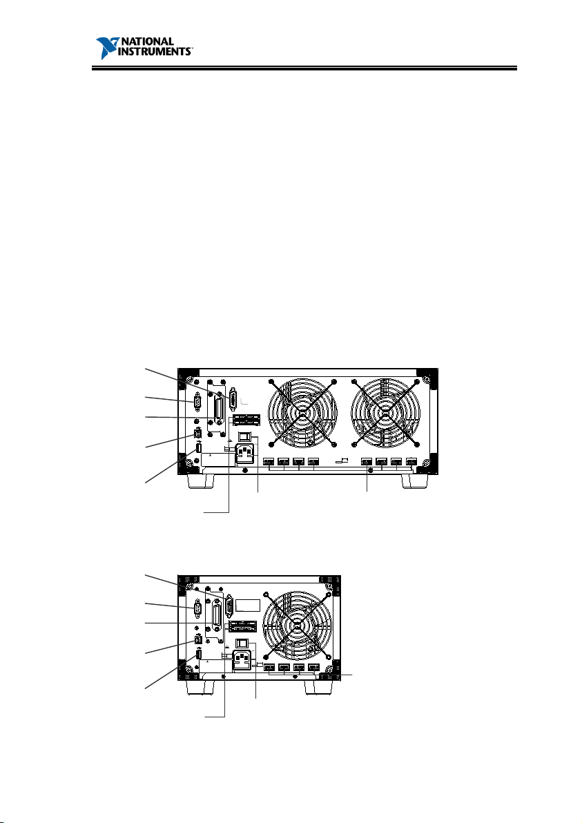
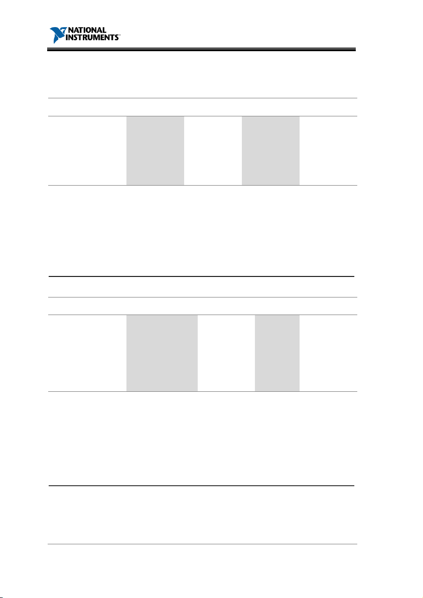
Go/NoGo
Output
GPIB
RS232C
USB-B
terminal
USB-A
terminal
Frame Control 1,2
Power switch,
Power Socket, Fuse
Channel
Control, 1~8
GROUNDING CONDUCTOR MUST BE CONNECTED TO GROUND.
NO OPERATOR SERVICEABLE COMPONENTS INSIDE.
FOR CONTINUED FIRE PROTECTION. REPLACE FUSE ONLY WITH
250V FUSE OF THE SPECIFIED TYPE AND RATING.
DO NOT REMOVE COVERS. REFER SERVICING TO QUALIFIED PERSONNEL.
TO AVOID ELECTRIC SHOCK THE POWER CORD PROTECTIVE
WARNING
AS SPECIFIED
FUSE RATING
230V
115V
REPLACE FUSE
T 3.15A
250V
AC
120 VA MAX
50/60 Hz
BEFORE REPLACING FUSE
DISCONNECT POWER CORD
RS232C
GPIB
GO / NG OUTPUT
FRAME CONT
1
2
SER. NO. LB
CH CONT 41CH CONT 31CH CONT 21CH CONT 1
1
10.0 mm
STRIP GAUGE
AWG 24
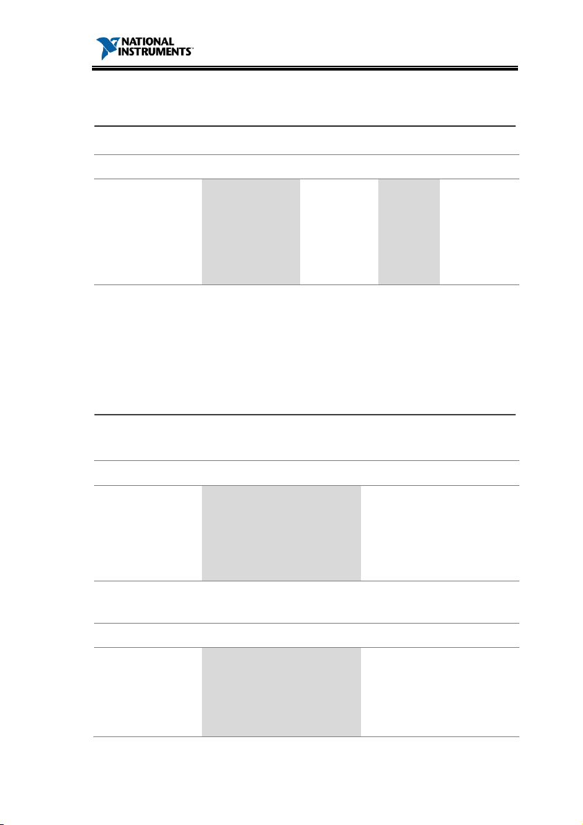
Power switch,
Power Socket, Fuse
Channel
Control, 1~4
Go/NoGo
Output
GPIB
RS232C
USB-B
terminal
USB-A
terminal
Frame Control 1,2
LAN
LAN
INTERFACE OVERVIEW
This manual describes how to use the RMX-400x
remote command functionality and lists the
command details. The Overview chapter describes
how to configure the RMX-400x USB/RS232
remote control interface.
Rear Panel Overview
RMX-4002
RMX-4000
5
Page 6
RMX-4000 Series Programming Manual
USB
PC side connector
Type A, host
RMX
connector
Type B,
Speed
1.1/2.0 (full speed)
Panel
1.
UTILITY
HELP
SHIFT
2.
F3
O
USB
Interface
Configure
Other
System
Info
InterfaceLoad
LOAD
USB
3.
4.
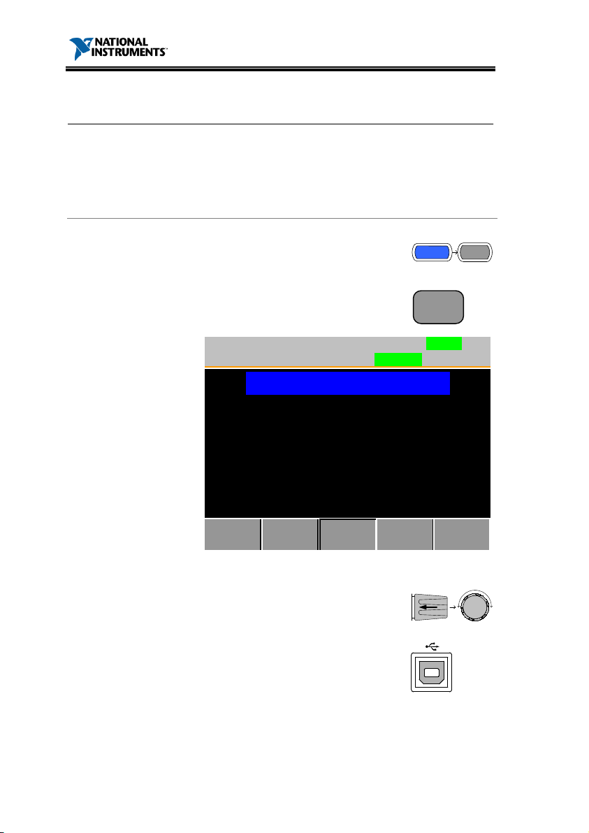
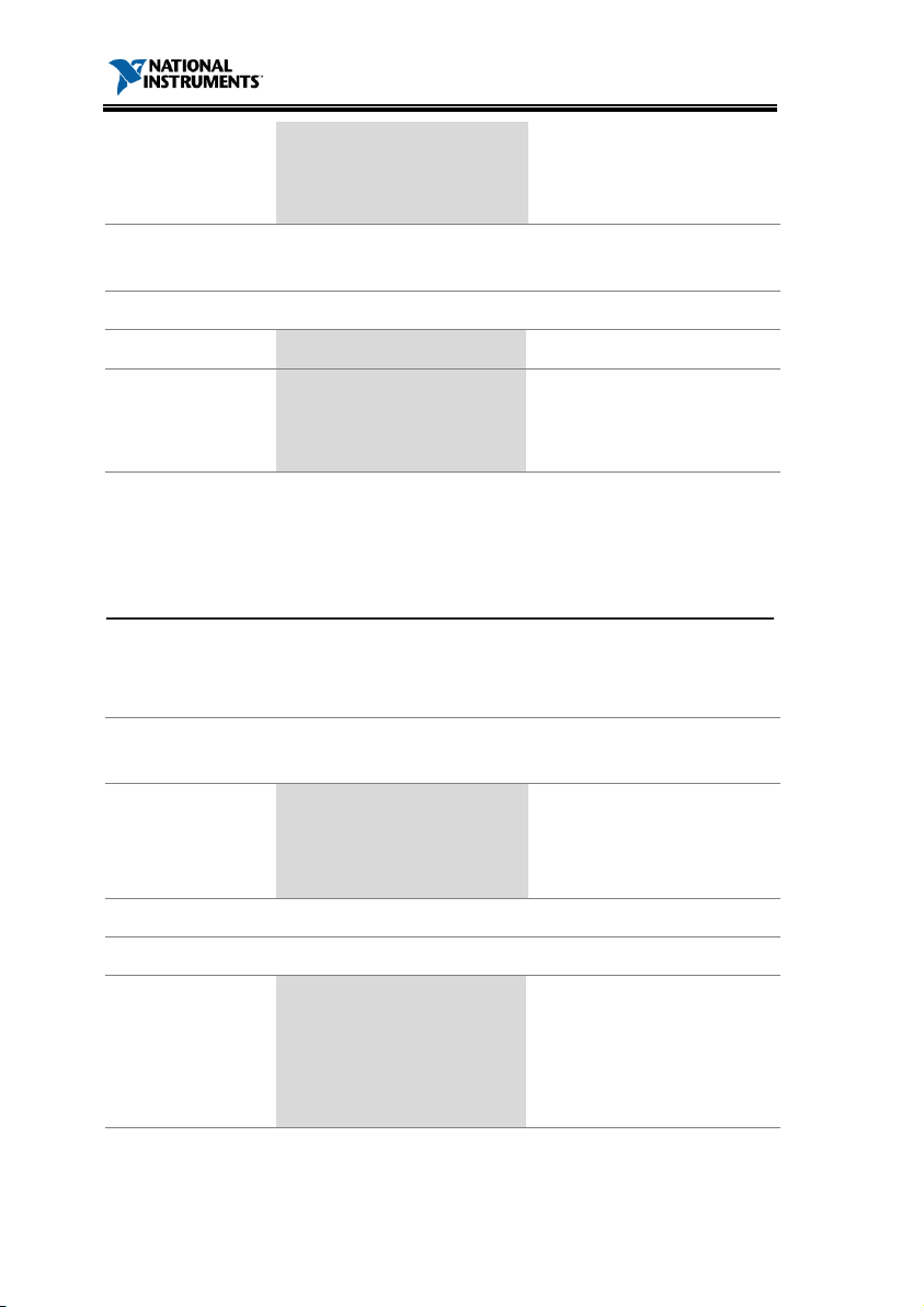
Configuring the USB Interface
Connection
Operat ion
-400x side
device
Press the Shift and Help keys to
access the Utility menu.
Press F3 (Interface Menu).
6
If the interface is not USB, use the
selector knob to choose USB.
Connect the USB cable to the
USB-B slave port on the rear.
Page 7

RMX-4000 Series Programming Manual
5.
website, ni.com.).
6.
Panel → System → Hardware tab.
7.
8.
details.
When the PC asks for the USB driver, select
pel_cdc_2000.inf (downloadable from the RMX400x product page on the National Instruments
On the PC, activate a terminal application such
as MTTTY (Multi-Threaded TTY). To check the
COM port number, refer to the Device Manager
in the PC. For Windows XP, select Control
Run this query command via the terminal
application:
*idn?
This command should return the manufacturer,
model number, serial number, and firmware
version in the following format:
NATIONAL INSTRUMENTS, RMX-4002, NI
00000001, V2.08T
You have finished configuring the command
interface. Refer to the other chapters for more
7
Page 8
RMX-4000 Series Programming Manual
R
C
Con
D
Baud rate
2400, 4800, 9600
Parity
None, Odd, Even
Data bit
8 (fixed)
Stop bit
1, 2
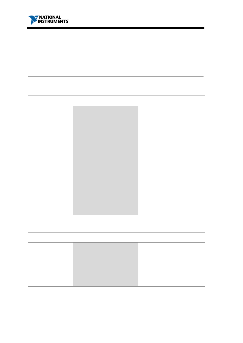
Panel
1.
2.
F3
O
RS232
Interface
ConfigureOther
System
Info
InterfaceLoad
Baud rate
Stop Bit
Parity
38400
1
None
LOAD
RS232
3.
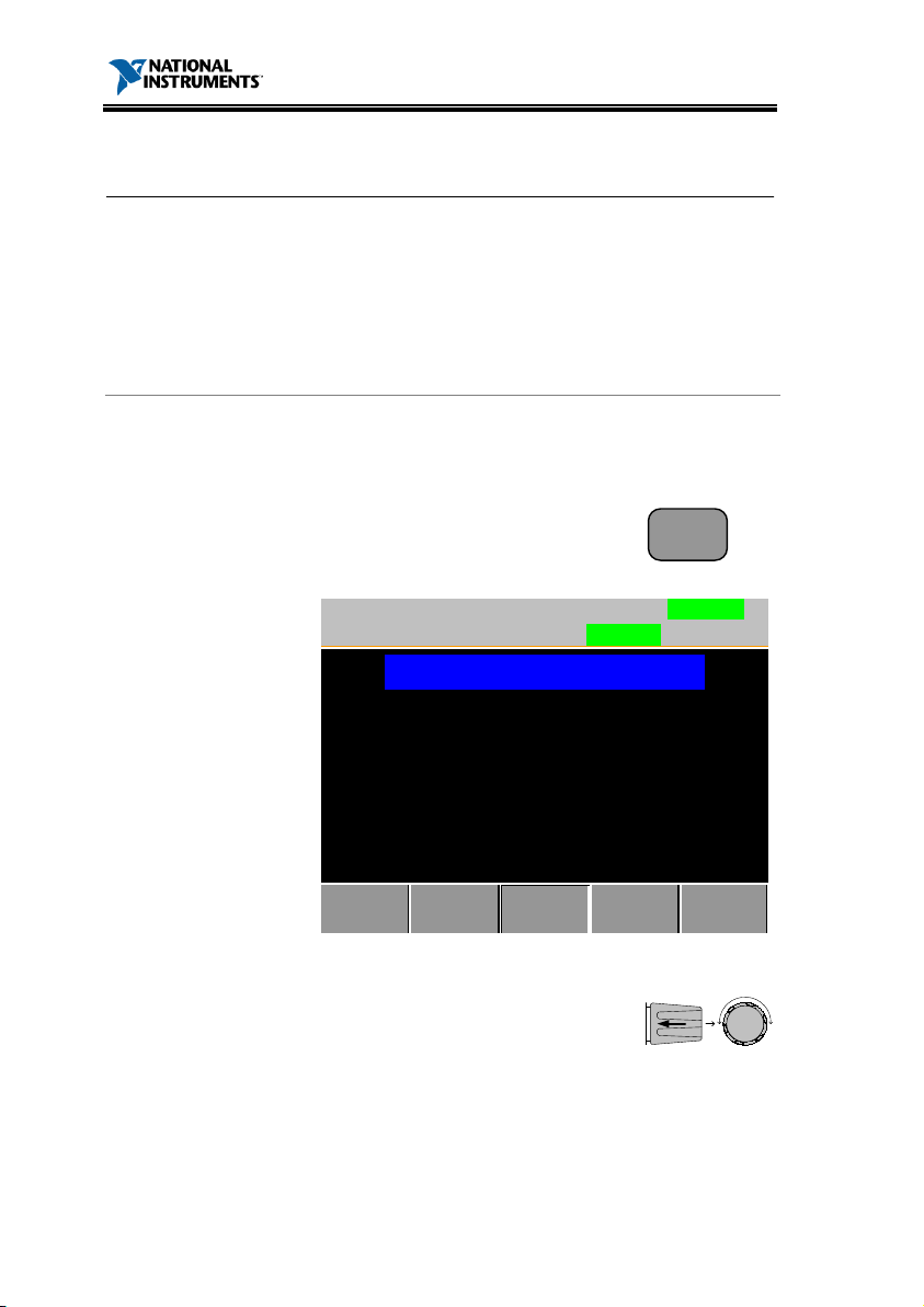
RS232C Interface Configurat ion
S232C
onfigurat ion
nector
B-9, Male
, 19200, 38400
Operat ion
Press the Shift and Help keys to
access the Utility menu.
Press F3 (Interface Menu).
If the interface is not set to RS232,
use the selector knob to change
the interface to RS232.
8
Page 9
RMX-4000 Series Programming Manual
4.
parity.
Baud
2400, 4800, 9600, 19200, 384
Stop
1,2
Parity
None,
5.
RS232C
Terminal
A
Invoke
(Multi
•
To check the CO
the Device Man
select
6.
Stop bits – None
Edit the baud rate, stop bit, and
pplicat ion
rate
bit range
range
Odd, Even
00
Connect the RS232C cable to the
rear panel port DB-9 male
connector.
a terminal application such as MTTTY
-Threaded TTY).
For RS232C, set the COM port, baud rate, stop
bit, data bit, and parity accordingly.
M port No. for RS232C, refer to
ager in the PC. For Windows XP,
Control Panel → System → Hardware tab.
Ensure the terminal application has the
following settings:
Baud rate – as per RMX-400x settings
Com port – as per PC settings (Device
Manager)
Parity – None
Data bits – 8
9
Page 10
Functionality
C
heck
Run this query command via the terminal
*idn?
This should return the
number,
the following
NATIONAL INSTRU
00000001, V2.08T
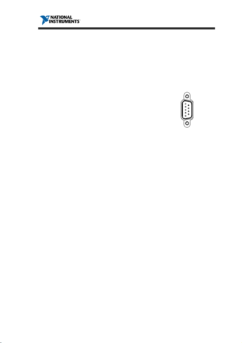
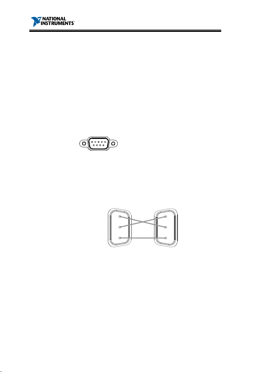
Pin
1 5
6 9
2: RxD (Receive data)
3: TxD (Transmit data)
5: GND
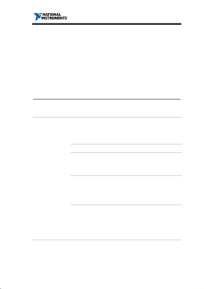
1,
PC
Use the Null Modem connection as s
following
Pin 2 RxD
Pin 3 TxD
Pin 5 GND
Pin 2 RxD
Pin 3 TxD
Pin 5 GND
PEL series PC
RMX-4000 Series Programming Manual
:
manufacturer, model
serial number, and firmware version in
format:
MENTS, RMX-4000/4002, NI
Assignment
Connect ion
diagram.
10
4, 6, 7,8, 9: No connection
hown in the
Page 11
RMX-4000 Series Programming Manual
Compat ible
S
•
•
Command
There are
and queries. A command sends inst
data to the electronic load
data or status information from the electronic load.
Command Types
Simple
A single
a parameter
Example
*O
Compound
Two or more commands
separated by a colon (:)
w
Example
UTILITY
Query
A query is a simple or compound
command followed by a question
mark (?).
ret
Example
UTILITY:SOUND?
COMMAND OVERVIEW
The Command overview chapter lists all the RMX400x commands and command queries. The
command syntax section describes the basic rules
you must apply when using commands.
Command Syntax
IEEE488.2, 1992 (fully compatible)
tandard
SCPI, 1994 (partially compatible)
Typ es
several different instrument commands
ructions or
, and a query receives
command with/without
PC
ith/without a parameter
:SOUND 1
A parameter (data) is
urned.
11
Page 12
Comma
nd Forms
Commands and queries have two different forms,
long
with the short form of the command in capitals
and the remainder (long form) in lower case.
Short
FETCh
:
VOLTage?
Short
Long
You can write
case,
complete. An incomplete comm
recognized.
Below are exa
commands.
LONG
F E TC h :VO LTa ge ?
FETCH:VO
fetch:voltage?
SHORT
FETC:VO
fetc:volt?
Square Brackets
Commands that
that the contents are optio
function is the same wit
bracketed items
Example:
:
= :
= :
Co
F
1
2
3
4
:PROGram:CHAin
<NR1>LF
1:
2:
3:
4:
RMX-4000 Series Programming Manual
and short. The command syntax is written
the commands in capitals or lower
as long as the short or long forms are
and will not be
mples of correctly written
mmand
ormat
12
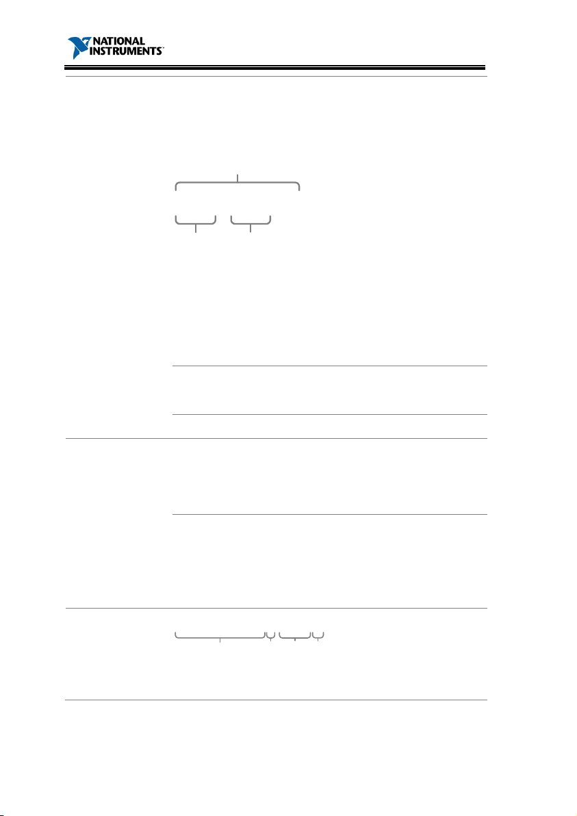
LOAD[:STATe]
LT?
contain squares brackets indicate
, as shown below.
LOAD:STATe
LOAD
nal. The command
h or without the square
Command header
Single space
Parameter
Message terminator
LTAGE?
Page 13

RMX-4000 Series Programming Manual
Parameter
Typ e D
Example
<Boolean>
Boolean
0, 1
<NR1>
integers
0, 1, 2, 3
<NR2>
decimal numbers
0.1, 3.14, 8.5
<NR3>
floatin
4.5e
<NRf>
any of NR1, 2, 3
1, 1.5, 4.5e
<NRf+>
NRf type
including MIN
(minimum) and
MAX (maximum)
limits of the
parameter
1, 1.5, 4.5e
MA
<aard>
Arbitrary
characters
<block data>
IEEE
block data is c
parts:
d
#216<
16_bytes_data
><NL>
ab c
e
a. Initialization character (#)
b. Digit length (in ASCII) of
the number of bytes
c. Number of bytes
d. Binary data
e. New line character
Message
T
LF^END
L
with END message
LF L
<dab>^END
Last data byte with END message
escription
logic
g point
ASCII
-488.2 binary block data. The
omprised of five
-1, 8.25e+1
X, MIN
-1
-1
erminator
ine feed code (hexadecimal 0A)
ine feed code
13
Page 14
RMX-4000 Series Programming Manual
Common
Commands
*CLS
*ESE
*ESR?
*IDN?
*OPC
*RCL
*RDT?
*RST
*SAV
*SRE
*STB?
*TST?
Abort
:ABORt
Channel
:CHANnel[:LOAD]
:CHANnel:SYNCon
:CHANnel:SYNCon:ALL
:CHANnel:ID?
:CHANnel:DISPlay
:CHANnel:MEMo
:MEMo?
List of Commands in Funct ional Order
........................................................................ 24
........................................................................ 25
....................................................................... 25
....................................................................... 26
........................................................................ 26
......................................................................... 27
....................................................................... 27
........................................................................ 29
........................................................................ 29
........................................................................ 29
........................................................................ 30
........................................................................ 30
14
...................................................................... 32
..................................................... 33
.................................................... 34
............................................. 34
............................................................ 35
..................................................... 35
....................................................... 36
..................................................................... 36
Page 15

RMX-4000 Series Programming Manual
Configu
:CONFigure:VOLTage:ON
:CONFigure:VOLTage:RANGe
:CONFigure:VOLTage:LATch
:CONFigure:AUTO:LOAD
:CONFigure:AUTO:MODE
:CONFigure:SOUND
:CONFigure:REMote
:CONFigure:LOAD
:CONFigure:PROTection:CURRent:STATe
:CONFigure:PROTection:CURRent:LEVel
:CONFigure:PROTection:VOLTage:STATe
:CONFigure:PROTection:VOLTage:L
:CON
:CONFigure:PROTection:POWer:LEVel
:CONFigure:PROTection:UVP:CLEar
:CONFigure:PROTection:UVP:L
:CONFigure:RESPonse
:CONFigure:RESEt
:CONFigure:GROup:UNITs
:CONFigure:GROup:MODE
Utility
:UTILity:AUTO:LOAD
:UTILity:AUTO:MODE
:UTILity:SOUNd
:UTILity:REMote
:UTILity:REMote:MODE
:UTILity:TIME
:UTILity:LOAD
:UTILity:IDENtify
:UTILity:FRAMe
re
........................................ 38
.................................. 39
.................................... 40
......................................... 40
........................................ 41
................................................. 41
................................................. 42
.................................................... 42
................ 43
................. 43
............... 45
EVel ................. 45
Figure:PROTection:POWer:STATe ................... 46
.................... 47
........................ 47
EVel......................... 48
.............................................. 48
.................................................... 49
....................................... 49
....................................... 50
............................................... 51
.............................................. 52
........................................................ 52
....................................................... 53
........................................... 53
........................................................... 54
.......................................................... 54
...................................................... 55
........................................................ 55
15
Page 16

RMX-4000 Series Programming Manual
Current
:CURRen
:CURRent:STATic:L1/L2
:CURRent:STATic:RISE/FALL
:CURRent:STATic:LOW:AVALue/BVALue
:CURRent:STATic:L
:CURRent:STATic:HIG
:CURRent:STATic:HIGH:RISE/FALL
:CURRent:DYNamic:L1/L2
:CURRent:DYNamic:RISE/FALL
:CURRent:DYNamic:T1/T2
:CURRent:DYNamic:LOW:L1/L2
:CURRent:DYNamic:LOW:RISE/FALL
:CURRent:DYNamic:
:CURRent:DYNa
:CURRent:DYNamic:HIGH:RISE/FALL
:CURRent:DYNamic:HIGH:T1/T2
Fetch
:FETCh:VOLTage?
:FETCh:
:FETCh:POWer?
:FETCh:STATus?
:FETCh:ALLVoltage?
:FETCh:ALLCurrent?
:FETCh:ALL
Load
:LOAD[:STATe]
:LOAD:SHORt[:STATe]
:LOAD:SHORt:KEY
:LOAD:PROTec
:LOAD:PROTection:CLEar
:LOAD:T
:LOAD:DELay
:LOAD:TYPE
CURRent? ..................................................... 72
IME? ............................................................ 79
16
t:STATic:RECall ........................................... 57
........................................... 58
................................... 59
................ 60
OW:RISE/FALL ........................... 61
H:AVALue/BVALue ................. 61
.......................... 62
......................................... 63
................................ 64
....................................... 65
............................... 66
........................ 67
LOW:T1/T2 .............................. 68
mic:HIGH:L1/L2 .............................. 68
...................... 69
............................... 70
..................................................... 72
........................................................ 73
........................................................ 73
................................................. 73
................................................. 74
Power? ................................................... 74
......................................................... 77
tion? ................................................. 79
........................................................... 80
............................................................ 80
............................................. 77
................................................... 78
......................................... 79
Page 17

RMX-4000 Series Programming Manual
Measure
:
:MEASure:CURRent?
:MEASure:POWer?
:
:MEASure:ALLVoltage?
:MEASure:ALLCur
:MEASure:
Mode
:MODE
OCP
Automat ion
:OCP:EDIT
:OCP:CHANnel:RANGe
:OCP:CHANnel:STARt
:OCP:CHANnel:END
:OCP:CHANnel:STEP:CURRent
:OCP:CHANn
:OCP:CHANnel:STEP:TIME
:OCP:CHANnel:DELay
:OCP:CHANnel:TRIGger
:OCP:CHANnel:ACTive
:OCP:STATu
:OCP:SAVE
:OCP:RESult?
:OCP:RUN
Tes t
MEASure:VOLTage? ................................................ 82
................................................ 82
................................................... 83
MEASure:SCAN ....................................................... 84
............................................ 84
rent? ............................................ 85
ALLPower? .............................................. 85
...................................................................... 87
:CHANnel? ............................................... 89
............................................. 90
.............................................. 90
................................................. 91
................................. 91
el:LAST ................................................ 92
....................................... 92
.............................................. 93
............................................ 93
............................................. 94
s? .......................................................... 94
............................................................... 95
............................................................ 95
................................................................. 95
17
Page 18

RMX-4000 Series Programming Manual
Program
:PROGram:STATe
:PROGram:FILE
:PROGram:SEQuenc
:PROGram:MEMory
:PROGram:SEQuence:SHORt:CHANnel
:PROGram:SEQuence:SHORt:TIME
:PROGra
:PROGram:ACTive
:PROGram:CHAin
:PROGram:ONTime
:PROGram:OFFTime
:PROGram:RUN
:PROGram:SAVE
:PROGram:PFTime
:PROGram:
Resistance
:RES
:RESista
:RESistance:STATic:RECall
:RESistance:STATic:LOW:AVALue/BVALue
:RESistance
:RESistan
:RESistance:STATic:HIGH:RISE/FALL
:RESis
:RES
:
:RESistance:DYNamic:HIGH:L1/L2
:RESistance:DYNamic:HIGH:RISE
:R
RUN
:RUN
m:SEQuence:MODE .................................. 101
18
istance[:STATic]:L1/L2 ..................................... 107
nce[:STATic]:RISE/FALL ............................. 108
ce:STATic:HIGH:AVALue/BVALue ............ 111
tance:DYNamic:LOW:L1/L2 .......................... 113
istance:DYNamic:LOW:RISE/FALL .................. 114
RESistance:DYNamic:LOW:T1/T2 .......................... 114
ESistance:DYNamic:HIGH:T1/T2 .......................... 117
....................................................................... 119
..................................................... 97
........................................................ 98
e .............................................. 98
................................................. 99
................... 99
........................ 100
.................................................. 102
.................................................... 102
................................................ 103
............................................... 104
...................................................... 104
..................................................... 105
.................................................. 105
CHAin:STARt......................................... 105
...................................... 109
............ 109
:STATic:LOW:RISE/FALL ...................... 110
...................... 112
.......................... 115
/FALL .................. 116
Page 19

RMX-4000 Series Programming Manual
SHOW
:SHOW[:DISPlay] dual channel
:SHOW
Sp
:SPECification:
:SPECification[:PASS]?
:SPECification[:PASS]:CHANnel/
ALLCh
:SPECification:VOLTage:H/L/C
:SPECification:CURRent:H/L/C
:SPECification:TEST:
Status
:STATus:CHANnel:CONDition?
:STATus:CHANnel:ENABle
:STATus:CHANnel:EVENt?
:STATus:CHANnel:
:STATus:CSUMmary:ENABle
:STATus:CSUMmary:EVENt?
:STATus:QUEStionable:CONDition?
:STATus:QUEStionable:ENABle
:STATus:QUEStionable[:EVENt]?
:STATus:QUEStionable:NTRansition/
:STATus:PREset
Voltage
:VOLTage:L1/L2
:VOLTage:RECall
:VOLTage:AVALue/BVALue
:VOLTage:CURRent
:VOLTage:MODE
:V
:VOLTage:
:VOLTage:
:VOLTage:
:VOLTage:
ecificat ion
............................... 120
[:DISPlay] single channel ............................. 121
UNIT ................................................ 122
........................................... 123
annel/VOLTage/CURRent? ........................... 123
............................... 124
................................ 124
............................................... 125
............................... 126
..................................... 127
..................................... 127
NTRansition/PTRansition .......... 128
.................................. 129
.................................. 130
....................... 130
.............................. 131
........................... 132
PTRansition .. 132
....................................................... 133
.......................................................135
.................................................... 136
.................................... 136
................................................. 137
.................................................... 138
OLTage:LOW:AVALue/BVALue .......................... 139
HIGH:AVALue/BVALue .......................... 140
LOW:CURRent ....................................... 141
HIGH:CURRent ...................................... 141
IMEasure ................................................ 142
19
Page 20

RMX-4000 Series Programming Manual
Power
:POWer:L1/L2
:POWer:CURRent
:POWer:RECall
:POWer:LOW:AVALue/BVALue
:POWer:LOW:CURRent
:POWer:HIGH:
:POWer:HIGH:CURRent
System
:SYSTem:ERRor?
:SYSTem:VERSion?
:SYSTem:SETup
:SYSTem:KLOCk
:S
. Error! Bookmark not defined.
Memory
:MEMory:SAVE:PREset
:MEMory:SAVE:PROGr
:MEMory:SAVE:ALLPreset
:MEMory:SAVE:SETup
:MEMory:RECall:PREset
:MEMory:RECall:PROGram
:MEMory:RECall:ALLPreset
:MEMory:RECall:SETup
:MEMory:FILE:PRESet
:MEMory:FILE:PROGram
:MEMory:FILE:SETup
:MEMory:FILE:SE
20
.......................................................... 144
.................................................... 145
........................................................ 146
AVALue/BVALue .............................. 148
..................................................... 150
................................................. 150
...................................................... 151
..................................................... 151
YSTemKEYLock:MODE
Quence ........................................ 157
.............................. 146
........................................... 147
.......................................... 149
........................................... 153
am ...................................... 153
...................................... 154
............................................ 154
.......................................... 154
..................................... 155
..................................... 155
........................................... 155
............................................. 156
........................................ 156
.............................................. 157
Page 21
RMX-4000 Series Programming Manual
Sequence
:SEQuence:STATe
:SEQuence:EDIT:POINt
:SEQuence:END
:SEQuence:END:LOAD
:SEQuence:POINt:RESist
:SEQuence:POINt:CURRent
:SEQuence:POINt:RISE/FALL
:SEQuence:POINt:TIME
:SEQuence:REPeat
:SE
:SEQuence:LOOP:STARt
:SEQuence:CHANnel:TIME
:SEQuence:RUN
:SEQuence:SAVE
:S
:SEQ
:SEQuence:TRIGger:IN:CHANnel
Global
:GLOBal:CONFigure:VOLTage:RANGe
:GLOBal:LOAD:SHORt
:GLOBal:MODE
.................................................. 159
.......................................... 160
...................................................... 160
........................................... 161
ance................................. 161
.................................... 162
................................. 163
.......................................... 163
................................................. 164
Quence:VOLTage:RANGe ................................. 165
........................................ 165
..................................... 166
..................................................... 167
.................................................... 167
EQuence:TRIGger:IN ........................................... 167
uence:TRIGger:OUT ....................................... 168
............................ 168
................... 170
........................................... 170
...................................................... 170
21
Page 22
RMX-4000 Series Programming Manual
Common Commands ............................... 24
COMMAND DETAILS
The Command Details chapter describes the
detailed syntax, equivalent panel operation, and
example for each command. For the list of all
commands, refer to page 14. Before programming
the RMX-400x electronic load, become familiar
with the Status registers, detailed on page 173.
Abort Subsystem ..................................... 32
Channel Subsystem ................................. 33
CONFIGURE Subsystem ........................... 38
Utility Subsystem .................................... 51
Current Subsystem .................................. 57
FETCH Subsystem ................................... 72
LOAD Subsystem ..................................... 77
Measure Subsystem ................................. 82
MODE Subsystem .................................... 87
OCP Test Automation Commands ............ 89
Program Subsystem ................................. 97
Resistance Subsystem ............................ 107
RUN Subsystem ..................................... 119
SHOW Subsystem .................................. 120
SPECIFICATION Subsystem .................... 122
STATUS Subsystem ............................... 126
Voltage Subsystem ................................ 135
Power Subsystem .................................. 144
SYSTEM Subsystem ............................... 150
22
............................................................. 151
Page 23

RMX-4000 Series Programming Manual
Memory Subsystem ............................... 153
SEQuence Subsystem ............................ 159
GLOBal Subsystem ................................ 170
23
Page 24
RMX-4000 Series Programming Manual
*CLS
*ESE
*ESR?
*IDN?
*OPC
*RCL
*RDT?
*RST
*SAV
*SRE
*STB?
*TST?
0B*CLS
St
Descript ion
Clears:
Channel Status Register
Channel Summary Register
Questionable Status Re
Standard Events Reg
Operation Status Register
Error Queue
When the *CLS command follows a program
message terminator <nl>
Output Queue
MAV bit
Refer to
Syntax
*CLS
Example
*
Common Commands
........................................................................ 24
........................................................................ 25
....................................................................... 25
....................................................................... 26
........................................................................ 26
......................................................................... 27
....................................................................... 27
........................................................................ 29
........................................................................ 29
........................................................................ 29
........................................................................ 30
........................................................................ 30
24
page 173.
CLS
atus Command
gister
ister
, the following is cleared:
Page 25
RMX-4000 Series Programming Manual
1B*ESE
Status Command
Descript ion
The
determines which events in the Standard Event
Status E
Bit (ESB) of the Status Byte register. Any bit
positions set to 1 enable the cor
Any enab
Byte register.
Synt
*ESE <NRf>
Parameter
<NRf>
Bit(s) Set
<NRf>
Bit(s) Set
4 QYE 32 CME
8 DDE 64 ~
16 EXE 128 ~
Example
*ESE 4
Sets CME and
events
Event Status Event
Register.
Query Syntax
*ESE?
Return Parameter
<NR1>
Bit(s) Set
<NR1>
Bi
4 Q
32 CME
QYE 8 DDE 64 ~
16 EXE 128 ~
Example
*ESE?
40
Returns the settings in
the Standard Event
Sta
Here
enabled.
2B*ESR?
Status Command
Standard Event Status Enable command
vent register can set the Event Summary
responding event.
led events set bit 5 (ESB) of the Status
Refer to page 180.
ax
0
DDE
in the Standard
YE
t(s) Set
tus Enable Register.
CME and QYE are
25
Page 26
RMX-4000 Series Programming Manual
Descript ion
Reads the Standard Event Status Register. This
command also
Register.
Query S
*
Return Parameter
<NR
Bit(s) Set
<NR1>
Bit(s) Set
4 QYE 32 CME
8 DDE 64 ~
16 EXE 128 ~
Example
*ESR
48
The return value i
status
standard Event Status
Register.
3B
System Command
Descript ion
Returns th
Que
*IDN?
Return Parameter
<aard>
Data
<aard>
Data
NATIONAL
INSTRUMENTS
Manufacturer
NI
00000001
Seri
RMX
Model
V2.08T
Firmware
Version
Example
*IDN?
NATIONAL INSTRUMENTS,
RMX
V2.08T
Retur
mainframe
identific
4B*OPC
Status Command
Descript ion
This command
Bit)
after
operations
clears the Standard Event Status
Refer to page 179.
*IDN?
ry Syntax
yntax
ESR?
1>
-4002
?
e electronic load identification.
s the
reading of the
al No.
-4002, NI 00000001,
sets the OPC (Operation Command
bit (bit 0) of the Standard Event Status Register
the mainframe has completed all pending
. Refer to page 179.
26
ns the
ation string.
Page 27

RMX-4000 Series Programming Manual
Syntax
*OPC
Example
*OPC
Sets the OPC bit.
Query
*OPC?
Return Parameter
<NR1>
Operat ion
<NR1>
O
0 P
1 Complete
Query
*OPC?
1
All pending operations
are completed.
5B*RCL
Status Command
D
The Recall Inst
instrument settings from a previously saved
memory setting.
Syntax
*
Parameter
<NRf>
Recall Memory Sett ing
1~120
1~120
Example
*RCL 1
Recalls
1
6B*RDT?
System Command
Descript ion
Returns the
order from
returned
Query
*RDT?
Return
<aard>
Occupied
2020L RMX
0 Empty channel
Syntax
Example
escription
ending
peration
rument State command restores the
RCL <NRf>
setting memory
.
.
Syntax
Parameter
load module type in each channel in
1~8. If no frame is present, a 0 is
channel
-4003 left channel
27
Page 28

RMX-4000 Series Programming Manual
Query
*RDT?
0,0
Chan
empty;
load module
channels
Example
,2020L,2020R,0,0,0,0
nels 1-2 and 5-8 are
the RMX-4003
occupies
3-4.
28
Page 29

RMX-4000 Series Programming Manual
7B*RST
Status Command
Descript ion
Resets the m
and
Syntax
*RST
Example
*RST
8B*SAV
All
Descript ion
Save
Syntax
*
Parameter
<NR
Save slot
1~120
1~120
E
*SAV 2
Saves data memory to
save slot 2.
9B*SRE
Status Command
Descript ion
The
which events in
MSS (Master summary bit)
causes
Refer to page 181 for details.
Syntax
*SRE <NRf>
Parameter
<NRf>
Bit(s) Set
<NRf>
Bit(
4 CSUM
32 ESB
8 QUES
16 MAV
Example
*SRE 12
Sets bits CSUM and
QUES in the Service
Request Enable register.
ainframe by forcing the ABORt, *CLS,
LOAD:PROT:CLE command.
xample
-Channels
s the data memory into the specified save slot.
SAV <NR1>
1>
Service Request Enable Command determines
the Status Byte Register can set the
. Any bit set to “1”
the MSS bit to be set.
s) Set
29
Page 30

RMX-4000 Series Programming Manual
Query Syn
*SRE?
Re
<NR1>
Bit(s) Set
<NRf>
Bit(s) Set
4 CSUM
32 ESB
8 QUES
16 MAV
Example
*SRE?
48
Re
Ser
Register. Here ESB and
MAV are returned.
10B*STB?
Status Command
Descript ion
Reads the Sta
c
If the Master Summary Status bit (MSS) is set, i
indicates there is a re
Query Syntax
*STB
Return Parameter
<NRf>
Bit(s) Set
<NRf>
Bit(s) Set
4 CSUM
32 ESB
8 QUES
64 MSS
16 MAV
Query Example
*STB?
36
Returns status of a byte
query in the Status Byte
Register. Here
and ESB are returned.
11B*TST?
Status Command
Descript ion
Performs a system self
passed. 1 is re
Query
*
Return Parameter
<NR1>
Test result
<NR1>
Test result
tax
turn Parameter
turns settings of the
vice Request Enable
tus Query Byte Register. The *STB?
ommand does not clear the register.
ason for a service request.
t
turned if a test failed.
Syntax
30
TST?
CSUM
-test and returns 0 if all tests
Page 31

RMX-4000 Series Programming Manual
0 Pass 1 Fail
Exa
*
>0
mple
TST?
31
Page 32

RMX-4000 Series Programming Manual
:ABORt
12B
All
Channe
D
Turns all electronic load
Syntax
:ABORt
Example
:
Abort Subsystem
...................................................................... 32
:ABORt
escription
l Command
s to OFF.
ABORt
32
Page 33

RMX-4000 Series Programming Manual
:CHANnel[:LOAD]
:CHANnel:SYNCon
:CHA
:CHANnel:ID?
:CHANnel:DISPlay
:CHANnel:MEMo
:MEMo?
13B:CHANnel[:LOAD]
Channel
Command
Descript ion
S
commands us
the channel in the display screen.
Syntax
:CHANnel
Parameter
<NRf+>
Channel
1~8 CH1 ~ CH8
MAX
CH8
MIN CH1
Exam
:CHAN 1
Sets channel 1 as the
specific channel.
:CHAN:LOAD 1
Sets channel
specific channel.
Query Synt
:CHANnel?
Return Parameter
<NR1>
Current specific channel
1~8 CH1 ~ CH8
LIST Lists available channels
Query Example
:CHA
1
Channel
available
Channel Subsystem
Nnel:SYNCon:ALL ............................................ 34
.................................................................... 36
elects the channel that the channel-specific
..................................................... 33
................................................... 34
............................................................ 35
.................................................... 35
...................................................... 36
-Specific
e. This command does not change
ple
ax
, 2
[:LOAD] <NRf+>
[LIST]
N? LIST
selected
1 as the
1 and 2 are
.
33
Page 34

RMX-4000 Series Programming Manual
14B:CHANnel:SYNCon
Cha
Command
Descript ion
Turns independent
Syntax
:CHANnel:SYNC
Parameter
ON
O
OFF
OFF
Example
:CHAN:SYNC ON
Enables the
channel
synchronized
commands
Query Syntax
:CHANnel:SYNC
Return Parameter
<NR1>
Sync Status
0 Independent
1 Independent
Query Example
:CHAN:SYNC?
0
Ind
to OFF for the channel.
15B:CHANnel:SYNCon:ALL
All
Descript ion
Turns independent mo
channels
Syntax
:CHANnel:SYN
Parameter
ON
ON for all channels
OFF
OFF
Example
:CHAN:SYNC
Enables
receive synchronized
commands
nnel-Specific
mode on or off for the channel.
/1
/0
on {ON|1|OFF|0}
N
current
to receive
.
on?
mode is OFF
mode is ON
ependent mode is set
-Channels
de on or off for all the
.
34
/1
/0
Con:ALL {ON|1|OFF|0}
for all channels
:ALL ON
all channels to
Page 35
RMX-4000 Series Programming Manual
16B:CHANnel:ID?
Channel
C
Descript ion
Queries the load module
Query Syntax
:CHANnel:ID?
Return Parameter
<aard>
Data
<aard>
Dat
NATIONAL
INST
Manufacturer
NI
00000001
Serial
Number
R
Channel
load id
V2.08T
Firmware
Version
Query Example
:C
NATIONAL
INSTRUMENTS,RMX
400
Returns the load
module identification
string.
17B
Ch
Co
Descript ion
Sets or queries which channel
mainframe display.
Syntax
:CHANnel
Parameter
<NRf+>
Channel
1~8 CH1 ~ CH
MAX
Last channel
MIN First channel
Example
:CHAN
Sets
on the display to ch
Query Syntax
:CHANnel
Return Parameter
<NR1>
Channel displayed
1~8 CH1 ~ CH8
MAX/MIN
Returns the allowable
maximum
ommand
identity.
-Specific
MX4003R
HAN:ID?
:CHANnel:DISPlay
RUMENTS
-
3,NI 00000001,V2.08T
:DISPlay <NRf+>
annel-Specific
mmand
is active on the
displayed
8
a
:DISP 1
to the active channel
1.
:DISPlay? [MAX|MIN]
or minimum
35
Page 36

RMX-4000 Series Programming Manual
Query Example
:CHAN
1
Channel 1
active
18B:CHANnel:MEMo
Channel
Command
Descript i
Creates or return
System Informat
This memo applies to
The memo replace
in the System Information screen.
Syntax
:CHANnel
Parameter
Return parameter
<
String containing memo
Example
:CHAN
memo”
Sets
is a memo”.
Query Syntax
:CHANnel
Query Example
:CH
this is a
Returns the memo
message.
19B
Channel
Query
Descript ion
Creates or returns the “memo” displa
System Information screen in the Utility Men
This memo applies to the mainframe. The memo
replace
System Information screen.
Syntax
:MEMo
Parameter/
Return parameter
<
String containing
Example
:MEM
Set the memo to “
a memo”
Query Syntax
:MEMo
:MEMo?
on
:DISP?
is currently
on the display.
-Specific
s the “memo” displayed on the
ion screen in the Utility menu.
only this specific channel.
s the serial number information
:MEMo <string>
/
string>
:MEM “this is a
to the memo to “this
:MEMo?
AN:MEM?
memo
-Specific
yed on the
u.
s the serial number information in the
<string>
string>
36
“this is a memo”
?
memo
this is
.
Page 37

RMX-4000 Series Programming Manual
Query Example
:MEM
this is a
Returns the
message.
?
memo
memo
37
Page 38

RMX-4000 Series Programming Manual
:CONFigure:VOLTage:O
:CONFigure:VOLTage:RANGe
:CONFigure:VOLTage:LATch
:CONFigure:AUTO:LOAD
:CON
:CONFigure:SOUND
:CONFigure:REMote
:CONFigure:LOAD
:CONFigure:PROTection:CURRent:STATe
:CONFigure:PROTection:CURRent:LEVel
:CONFigure:PROTecti
:CONFigure:PROTection:VOLTage:LEVel
:CONFigure:PROTection:POWer:STATe
:CONFigure:PROTection:POWer:LEVel
:CONFigure:PROTection:UVP:CLEar
:CONFigure:PROTection:UVP:LEVel
:CONFigure:RESPonse
:
:CONFigure:GROup:UNITs
:CONFigure:GROup:MO
20B
Channel
Command
Descript ion
Sets Von (vo
values are channel and load module specific.
Syntax
:CONFigure:VOLTage:ON <NRf>[MV
Parameter
<NRf>
Von
3 3
30MV
30
30V 30
CONFIGURE Subsystem
Figure:AUTO:MODE ......................................... 41
:CONFigure:VOLTage:ON
38
CONFigure:RESEt ................................................... 49
ltage on value). The allowable Von
[ MV|V|KV]
N ......................................... 38
................................... 39
................................... 40
......................................... 40
.................................................. 41
................................................ 42
................................................... 42
................ 43
.................. 43
on:VOLTage:STATe ............... 45
................ 45
.................. 46
..................... 47
............................................. 48
......................... 47
........................ 48
....................................... 49
DE ...................................... 50
-Specific
V
|V|KV]
mV
V
Page 39

RMX-4000 Series Programming Manual
Example
:CONF:VOLT:ON 30
Set Von to 30 mV.
Query Syntax
:CONFigu
Return
<NR2>
Von
1 1
Query
:CONF:VOLT:ON
0.03
Von is set
V
21B
Channel
Command
Descript ion
Sets Voltage range
Syntax
:CON
Parameter
<NRf>[ V]
Range
16 Low range*
80V High range*
L Low range
H Hig
*Load m
Example
:CONF:VOLT:
Set
the channel.
Query Syntax
:C
Return
<NR2>
Range
16 Low
4005
125 Low
80 High
4005
500 Hi
Query Example
:CONF:VOLT:
500
Returns the voltage
range. In this case
for the RMX-4006.
Parameter
Example
re:VOLTage:ON?
1 unit = 1 V
MV
?
:CONFigure:VOLTage:RANGe
Figure:VOLTage:RANGe <NRf>[V]|L|H
, L, H
odule dependent, RMX-4003 shown.
for CC mode.
RANG L
value (volts)
V
as 30 mV (0.03
).
-Specific
h range
s the range to Low for
Parameter
ONFigure:VOLTage:RANGe?
RANG?
RMX-4003, 4004,
RMX-4006
RMX-4003, 4004,
gh RMX-4006
, high
39
Page 40

RMX-4000 Series Programming Manual
22B:CONFigure:VOLTage:LATch
Channel
Command
Descript ion
Turn Von Latch on o
Synt
:CONFigure:VOL
Parameter
{OFF|0|ON|1}
Von Latch
OFF
Off
ON
On
Example
:CONF:VOLT:LAT 1
Sets Von latch to ON.
Query Syn
:CONFigure:VOLTage:LATch?
Return Parameter
<NR1>
Von latch status
0 Latched O
1 Latched
Query Example
:C
1
Von latch is set to ON.
23B
All
Descript ion
Configures the
Off at start up.
Syntax
:CONFigure
Parameter
{OFF|0|ON|1}
Auto Load
OFF
Off
ON
On
Example
:CONF:
Configures Auto Load to
On
Query Syntax
:CONFigure
Return Parameter
Auto Load Status
0 Off
1 On
r off for the specific channel.
-Specific
ax
/0
/1
tax
ONF:VOLT:LAT?
:CONFigure:AUTO:LOAD
:AUTO:LOAD {OFF|0|ON|1}
Tage:LATch {OFF|0|ON|1}
ff
On
Channels
electronic load for Auto Load On or
/0
/1
AUTO:LOAD ON
<NR1>
40
.
:AUTO:LOAD?
Page 41

RMX-4000 Series Programming Manual
Query Example
:CONF:
1
Auto load is On.
24B:CONFigure:AUTO:MODE
All
Descript ion
C
or Load.
Syntax
:CONFigure
Parameter
P
Auto Lo
PROGRAM
PROGRAM
LOAD
LOAD
Example
:CONF:
Configures Auto Load to
LOAD
Qu
:CONF
Return Parameter
<NR1>
Auto Load
0 PROGRAM MODE
1 LOAD MODE
Query Example
:CONF:
1
Auto load m
LOAD mode
25B
Channel
Command
Descript ion
Sets the sound of each
Syntax
:CONFigure
Parameter
OFF
Off
ON
On
Example
:CONF
Configures th
the specific
On.
Query Syntax
:CONFigure
ery Syntax
AUTO:LOAD?
Channels
onfigures the Auto Load mode as (run) Program
:AUTO:MODE PROGRAM/0, LOAD/1
ROGRAM/0, LOAD/1
/0
/1
ad Mode
AUTO:MODE 1
igure:AUTO:MODE?
Type Status
AUTO:MODE?
ode is to
.
:CONFigure:SOUND
/0
/1
:SOUND ON
-Specific
load module on or off.
:SOUND {OFF|0|ON|1}
e sound for
channel to
:SOUND?
41
Page 42

RMX-4000 Series Programming Manual
Return Parameter
<NR1>
SOUND Status
0 Off
1 On
Query Example
:C
0
Sound is off for the
specific channel.
26B:CONFigure:REMote
All Channels
Descript ion
Turns remote con
Syntax
:CONFigure:REMOTE
Parameter
OFF
Off
ON
On
Example
:CONF:
Turns Remote c
on.
27B:CONFigure:LOAD
System Command
Descript ion
Configures
or Updated.
Syntax
:CONFi
Example
:CONF:
Sets the load module
selector knob as
Updated.
Parameter
OLD
Old
UPDATED
Updated
Example
:CONF:
Configuration type set as
OLD.
Query Syntax
:CONFigure
Return Parameter
<NR1>
C
0 Old
ONF:SOUND?
/0
/1
REM 1
trol on or off for all interfaces.
{OFF|0|ON|1}
ontrol
the load module selector knob as OLD
42
gure:LOAD {OLD|0|UPDATED|1}
LOAD UPDATED
/0
/1
LOAD OLD
:LOAD?
onfigurat ion type
Page 43

RMX-4000 Series Programming Manual
1 Updated
Query Example
:CONF:
0
Sets the load module
selector configuration
type as OLD.
28B:CONFigure:PROTection:CURRent:STATe
Channel
Command
Descript ion
Sets the current protection for the specific channel
on
cleared.
Syntax
:CONFigure:PROTection:CURRent:STATe
{OFF|0|ON|1|
Par
CLEAR
Cleared
OFF
Off
ON
On Example
:CONF:PROT:CURR:STAT 1
Turns on current protection.
Query Syntax
: CONFigur
Return Parameter
<NR1>
Current Protection
0 Off
1 On
2 Clear
Query Example
:CONF:PROT:CU
1
Current protection is
turned on.
29B:CONFigure:PROTection:CURRent:LEVel
Channel
Command
Descript ion
Sets the cu
current/specific channel.
any applicable level or to the channel
max
Syntax
:CONFigure:PROTection:CURRent:LEVel
<NRf>[A]
ameter
LOAD?
-Specific
or off. The current protection can also be
CLEAR|2}
/2
/0
/1
e:PR OTection:CURRent:STATe?
RR:STAT?
rrent protection level for the
imum/minimum.
|MIN|MAX
-Specific
You can set the level to
43
Page 44

RMX-4000 Series Programming Manual
Parameter
<NRf>
Current
.3 300
0.
30
300MA
300
MIN Sets to the minimum level
MAX
Sets the current limit to
the maximum level
Example
:CONF
MAX
Sets the current limit to
20.40
Query Syntax
: CONFigure:PROTection:CURRent:LEVel?
Retu
<NRf>
Current protection level
1 1
MAX/MIN
Returns the allowable
maximum and minimum
Query
:CONF:PROT:CURR:LEV?
0.30
Current protection level
is at 30
rn Parameter
Example
3A
:PROT:CURR:LEV
1 unit = 1 A
Protect ion Level
mA
0 mA
mA
A (RMX-4003)
[MIN|MAX]
A
0 mA.
44
Page 45

30B:CONFigure:PROTection:VOLTage:STATe
Channel
Comma
D
escription
Sets the voltage protection for the current/specific
channel on or off.
protection.
Syntax
:CONFigure:PROTection:VOLTage:STATe
{OFF|0|ON|1|
Parameter
CLEAR
Clear
OFF
Off
ON
On
Example
:CO
Turns on voltage
protection.
Query Syntax
: CONFigure:PROTection:VOLTage:STATe?
Return Parameter
<NR1
V
0 Off
1 On
2 C
Query Example
:CONF:PROT:VOLT:STAT?
0
Voltage protection is
currently
31B:CONFigure:PROTection:VOLTage:LEVel
Channel
Command
Descript ion
Sets the voltage protection level for the
current/s
any applicable level or to the channel
maximum/minimum.
Syntax
:CONFigure:PROTection:VOL
<NRf>[V]
Parameter
<NRf>
Voltage Protect ion Level
30 30
30V 30
RMX-4000 Series Programming Manual
-Specific
nd
Also can clear the voltage
CLEAR|2}
/2
/0
/1
NF:PROT:VOLT:STAT 1
>
oltage Protect ion state
lear
off.
-Specific
pecific channel. You can set the level to
|MIN|MAX
Tage:LEVel
V
V
45
Page 46
RMX-4000 Series Programming Manual
MIN Sets to the minimum level
M
Sets the voltage limit to
the maximum level
Example
:CONF:PROT:VOLT:LEV
MAX
Sets the voltage limit to
81.6
Qu
: CONFigure:PROTection:VOLTage:LEVel?
Return Parameter
<NRf>
Voltage protect ion level
1
1.00
MAX/MIN
Returns the allowable
maximum and minimum
Query Example
:CONF:PROT:VOLT:LEV?
81.6000
Voltage protection level
is
32B:CONFigure:PROTection:POWer:STATe
Channel
Command
Descript ion
Sets the power protection for the c
channel on or off.
protection.
Syntax
:CONFigure:PROTection:
{OFF|0|ON|1|
P
CLEAR
Cleared
OFF
Off
ON
On
Example
:CONF:PROT:
Turns on
Query Syn
: CONFigure:PROTection:
Return Parameter
<NR1>
Power
0 Off
1 On
2 Clear
Query Example
:CONF:PROT:
1
Power
currently on.
AX
V (RMX-4003).
ery Syntax
arameter
[MIN|MAX]
.00
1 unit = 1 V
V
at 81.6 V.
-Specific
urrent/specific
Also can clear the power
POWer:STATe
CLEAR|2}
/2
/0
/1
POW:STAT 1
power protection.
tax
POW: STAT?
46
POWer:STATe ?
Protect ion
protection is
Page 47

RMX-4000 Series Programming Manual
33B:CONFigure:PROTection:POWer:LEVel
Channel
Command
Descript ion
Set
current/specific channel.
any applicable level or to the channel
maxim
Syntax
:CONFigure:PROTection:
<NRf>[
Parameter
<NRf>
Power
200 200
2
200
MIN Sets to the minimum level
MAX
Sets the
maximum level
Example
:CONF:PROT:
MAX
Sets t
102
Query Syntax
: CONFigure:PROTection:
Return Parameter
<NRf>
Pow
1 unit = 1
Returns the power
protect ion level in
MAX/MIN
Returns the allowable
maximum and minimum
Qu
:CONF:PROT:POW:LEV?
75
Power protection level is
at 75
34B:CONFigure:PROTection:UVP:CLEar
All
Command
Descript ion
Clears the under voltage power protection status.
Syntax
:CONFigure:PROTection:
Example
:CONF:PROT:
Clear
protection.
s the power protection level for the
You can set the level to
um/minimum.
-Specific
ery Example
00W
W]|MIN|MAX
POW:LEV
W
POWer:LEVel
Protect ion Level
W
W
power limit to the
he power limit to
W (RMX-4003).
POWEr:LEVel? [MIN|MAX]
er protect ion level
watts
W.
-Channel
UVP:CLE
UVP:CLEar
s the under voltage
47
Page 48

RMX-4000 Series Programming Manual
35B:CONFigure:PROTection:UVP:LEVel
Channel
Command
Descript ion
Sets the und
current/specific channel.
any applicable level or to the channel
maximu
Syntax
:CONFigure:PROTection:
<NRf>[W]
Parameter
<NRf>
UVP
20 20
20V 20
MIN S
(OFF)
MAX
Sets the
the maximum level
Example
:CONF:PROT:
Sets the
Query Syntax
:CONFigure:PROTection:
Return Parameter
<NRf>
Power protection level
1 unit = 1
Returns the UVP level as
volts
MAX/MIN
Returns the allowable
maximum and minimum
Query Example
:CONF:PROT:UVP:LEV?
75
UVP
36B:CONFigure:RESPonse
Channel
Command
Descript ion
Sets or queries the response rate
c
Syntax
:CONFigure:RESPonse
Parameter
NORMAL
Normal
er voltage protection level for the
You can set the level to
m/minimum.
-Specific
UVP:LEVel
|MIN|MAX
Level
V
V
ets to the minimum level
voltage limit to
UVP:LEV MIN
UVP:LEVel? [MIN|MAX]
UVP limit to OFF.
V
level is at 75 V.
-Specific
for the specific
hannel.
48
/0
{NORMAL|0|FAST|1}
Page 49

RMX-4000 Series Programming Manual
FAST
Fast Example
:CONF:
Response s
Query Syntax
: CONFigure:
Return Parameter
<NR1>
Response
0 Normal
1 Fast
Query Example
:CONF
1
Response is Fast
37B:CONFigure:RESEt
Channel
Command
Descript ion
Recalls the original factory default settings.
Synt
:CONFigure:
Example
:CONF:
38B:CONFigure:GROup:UNITs
Channel
Command
Descript ion
Sets or quer
modules (
use in the parallel mode.
Syntax
CONFigure:GROup
Parameter
<NRf>
Number of units
MIN Sets to the minimum
number
MAX
Sets
number
Exa
CONF:GRO:UNIT
Sets the parallel mode to 2
units.
Query Syntax
CONFigure:GROup:UNITs
Return Parameter
<NR
Retur
units
/1
RESP 0
et to normal.
ax
RESPonse?
:RESP?
.
-Specific
RESEt
RESE
-Specific
ies the number of single channel load
RMX-4005 or RMX-4006) that you can
:UNI Ts <NRf>|MIN|MAX
mple
1>
to the maximum
2
? [MIN|MAX]
ns the number of
49
Page 50

RMX-4000 Series Programming Manual
MAX/MIN
Returns the allowable
maximum and minimum
Query Example
:
2
2 units are set
parallel mode.
39B:CONFigure:GROup:MODE
Channel
Command
Descript ion
Sets or queries the parallel mode.
Syntax
:C
Parameter
SYNC, 0
Sync mode
PARALLEL, 1
Parallel mode
Example
:CONF:GRO:MODE
S
SYNC.
Query Syntax
:CONFigure:GROup:MODE
Return Parameter
Sync mode
1 Parallel mode
Query Example
:
0
T
currently set to SYNC.
CONF:GRO:UNIT?
for the
-Specific
ONFigure:GROup:MODE {SYNC|0|PARALLEL|1}
0
ets the parallel mode to
?
0
CONF:GRO:MODE?
he parallel mode is
50
Page 51

RMX-4000 Series Programming Manual
:
:UTILity:AUTO:MODE
:UTILity:SOUNd
:UTILity:REMote
:UTILit
:UTILity:TIM
:UTILity:LOAD
:UTILity:IDENtify
:UTILity:
40B:UTILity:AUTO:LOAD
System Command
Descript ion
Sets the m
mainframe turn
Syntax
:UTIL
Parameter
OFF
T
ON
Turns auto loading on
Example
:UTIL:AUTO:LOAD 1
Turns auto loading
on.
Query Syntax
:UTIL
Return
<NR1>
Auto load
0 Auto loading is off
1 Auto loading is on
Query
:UTIL:AUTO:LOAD
1
The main frame is
cur
to auto load.
Utility Subsystem
UTILity:AUTO:LOAD ............................................... 51
y:REMote:MODE ........................................... 53
FRAMe ........................................................ 55
.............................................. 52
........................................................ 52
....................................................... 53
E ........................................................... 54
.......................................................... 54
...................................................... 55
ainframe to auto mode. On startup, the
s loads/programs on.
Parameter
Example
ity:AUTO:LOAD {OFF|0|ON|1}
/1
/0
urns auto loading off
ity:AUTO:LOAD?
status
?
rently configured
51
Page 52

RMX-4000 Series Programming Manual
41B:UTILity:AUTO:MODE
System Command
Descript ion
Sets the mainfram
Upon startup the mainframe
turn on loads or automatically run the last
program.
Sy
:UTIL
Parameter
PROGRAM
Sets the auto load mode to
program
LOAD
Sets the auto
load
E
:UTIL:AUTO:
Auto load mode is set to
load.
Query Syntax
:UTIL
Return Parameter
Auto load mode
0 Pr
1 Load
Query
:UTIL:AUTO:MODE?
0
Auto load mode is set to
p
42B
S
Des
Turns the sound on/off for the mainframe/load
modules.
Syntax
:UTIL
Paramete
OFF
Turns sound off
ON
Turns sound on
Example
:UTIL:SOUN 1
Turns sound on.
Query Syntax
:UTIL
Return P
<NR1>
Sound
e auto mode as load or program.
can automatically
ntax
xample
<NR1>
Example
:UTILity:SOUNd
cription
ity:AUTO:MODE {PROGRAM|0|LOAD|1}
/0
/1
MODE 1
ity:AUTO:MODE?
ogram
rogram.
ity:SOUNd {OFF|0|ON|1}
load mode to
ystem Command
r
/0
/1
arameter
52
ity:SOUNd?
Page 53

RMX-4000 Series Programming Manual
0 Off
1 On
Query
:UTIL:SOUN?
0
Sound
off.
43B
System Command
D
Turns the remo
Syntax
:UTIL
Parameter
OFF
Tur ns
ON
Tur ns r
Example
:UTIL:REM 1
Turns
44B:UTILity:REMote:MODE
System Command
Descript ion
S
mode, the
interface time of no more
mo
normal mode
update the screen in
Syntax
:UT
Parameter
NORMAL
NORMAL
FAST
FAST
Example
:UTIL:REM
Turns remote mod
fast.
Example
:UTILity:REMote
escription
is currently set to
te control on or off.
ity:REMote {OFF|0|ON|1}
/0
/1
Remote control off
emote control on
remote control on.
ets the remote mode to fast or normal. In fast
panel interface is deactivated with an
than 10 ms. Normal
de has an interface time of 30~130 ms. In
, the display interface continues to
real time.
ILity:REMote:MODE {NORMAL|0|FAST|1}
/1
/0
:MODE 1
e to
53
Page 54

RMX-4000 Series Programming Manual
45B:UTILity:TIME
System Command
Descript ion
Sets the
Syntax
:UTIL
Paramete
[
1
2
3
“201511131300”
1
2
3
Year
Month/Day
Time (24 hours)
Example
:UTIL:TIME
Sets the time to 1:00 p.m., January 3, 2015.
Query Syntax
:UTIL:TIME?
Return Parameter
1
2
3
2015/11/13/13:00
1
2
3
Year
Mo
Time (24 hours)
Query
:UTIL:TIME?
20
The date is
13
p.m.
46B:UTILity:LOAD
System Command
Descript ion
Sets the knob control style. You can set the load
module control
(OLD
mainframe (UPDATED).
Syntax
:UTIL
Parameter
O
Old
U
Updated
Example
:UTIL:LOAD 1
Set the knob style to
independent.
date and time on the mainframe.
r
Example
ity:TIME [aard]
aard]
“201501031343”
[aard]
15/11/13/13:00
knobs to operate independently
style) to the mainframe or with the
nth/Day
November
, 2015. The time is 1:00
ity:LOAD {OLD|0|Updated|1}
LD/0
PDATED/1
54
Page 55

RMX-4000 Series Programming Manual
Query Syntax
:UTIL
Return Parameter
<NR
Knob style
0 Old
1 Updated
Query
:UTIL:L
The knob style is set to
Updated.
47B:UTILity:IDENtify
Syst
Descript ion
Flashes a message “I am Here!” on the mainframe
display. This command is useful
RMX
on the mainframe also turn
Syntax
:UTIL
P
OFF
Tur ns
ON
Tur ns
Example
:UTIL
Turns
48B
System Command
D
Turns
Syntax
:UTIL
Parameter
{OFF|0|ON|1
Frame Link
OFF
o
ON
on
Example
:UTIL:
Turns
Query Syntax
:UTIL
Return Parameter
<NR1>
F
0 Off
1 O
Example
arameter
:UTILity:FRAMe
escription
ity:LOAD?
1>
OAD? 1
em Command
to identify an
-400x mainframe in a group. Pressing any key
s off the message.
ity:IDENt ify {OFF|0|ON|1}
/0
/1
:IDEN 1
message off
message on
on the message.
Frame Link on or off.
ity:FRAMe {OFF|0|ON|1}
}
/0
/1
FRAM 1
ity:FRAMe?
ff
Frame Link on.
rame Link
n
55
Page 56

RMX-4000 Series Programming Manual
Query Example
:UTIL:
0
Frame Link is on.
FRAM?
56
Page 57

RMX-4000 Series Programming Manual
:CURRen
:CURRent:STATic:L1/L2
:CURRent:STATic:RISE/FALL
:CURRent:STATic:LOW:AVALue/BVALue
:CURRent:STATic:LOW:RISE/FALL
:CURRent:STAT
:CURRent:STATic:HIGH:RISE/FALL
:CURRent:DYNamic:L1/L2
:CURRent:DYNamic:RISE/FALL
:CURRent:DYNamic:T1/T2
:CURRent:DYNamic:LOW:L1/L2
:CURRent:DYNa
:CURRent:DYNamic:LOW:T1/T2
:CURRent:DYNa
:CURRent:DYNamic:HIGH:RISE/FALL
:CURRent:DYNamic:HIGH:T1/T2
49B
Channel
Command
Descript ion
Sets or queries whethe
currently active
Syntax
:
Parameter
A
A
B
B
Example
:
Makes B Value the active
value
Query S
:
Return Parameter
<NR1
Value
0 A
Current Subsystem
t:STATic:RECall .......................................... 57
............................................ 58
.................................... 59
................. 60
........................... 61
ic:HIGH:AVALue/BVALue ................ 61
.......................... 62
........................................ 63
................................ 64
........................................ 65
............................... 66
mic:LOW:RISE/FALL ....................... 67
............................... 68
mic:HIGH:L1/L2 ............................... 68
....................... 69
.............................. 70
:CURRent:STATic:RECall
yntax
CURRent:STATic:RECall {A|0|B|1}
/0
/1
CURR:STAT:REC 1
CURRent:STATic:RECall?
-Specific
r A Value or B Value is the
value in CC static mode.
.
>
57
Page 58

RMX-4000 Series Programming Manual
1 B
Query Example
0
A Value is active
50B:CURRent:STATic:L1/L2
Channel
Command
Descript ion
S
mode
command is range
is Low, the command
range settings.
Syntax
:CURRent:STATic:L
Parameter
<
L1 1 Sets A Value to 1
L2 2 Sets B Value to 2
L
Sets A Value to 1
channel
L1
Sets A Value to the
minimum level for the
specific channel
L1 MAX
Sets A
maximum
specific channel
Exam
:CURR:STAT:L
Sets
the current range.
Que
:CURRent:STATic:L
Return P
<NR2>
Current
1 unit = 1
Returns the A Value (L1) or
B
MAX/MIN
Returns the allowable
maxim
:CURR:STAT:REC?
.
-Specific
ets the A/B Value for constant current static
, where L1 is A Value and L2 is B Value. The
dependent. If the current range
applies to only the low-
NRf+>[A]
1|L2 <NRf+>[A]
A
A
1 1A
A (single
only)
MIN
Value to the
level for the
ple
ry Syntax
arameter
58
1 1
[MAX|MIN]
A
A Value to 1 A for
1?/L2? [MAX|MIN]
Value (L2) current
um and minimum
Page 59

RMX-4000 Series Programming Manual
Query Example
:CURR:STAT:
10.
Returns the m
current allowed for the
channel. (RMX-4003)
Q
:CURR:STAT:
Returns the current
setting (2 A) for B Value
51B
Channel
Command
Des
Sets the
The c
range is Lo
range settings
Syntax
:CURRent:STATic:
Parameter
<NRf+>[A/
Slew
RISE/FALL 0.078
Sets the ris
rate
RISE/FALL 1
Sets the ris
rat
RISE/FALL MIN
Sets
rising/falling slew rate
RISE/FA
Sets to the fastest
rising/falling slew rate
Exam
:CURR:STAT:RISE .01
Sets
to 0.01
Qu
: CURRent:STATic:
Ret
<NR2>
Slew rate
1 unit
Returns the slew rate
M
Returns the allowable
maximum and minimum
Query
:CURR:STAT:RISE? MIN
0.
T
the risin
0.
specific channel.
L2? MAX
2
uery Example
L2? 2
:CURRent:STATic:RISE/FALL
cription
ple
slew rate for constant current static mode.
ommand is range dependent. If the current
w, the command applies to only the low
.
µs]
LL MAX
RISE/FALL <NRf+>[A/µs]
rate
A/µs
to 0.078 A/µs
e to 1 A/µs
to the slowest
the rising slew rate
A/µs.
aximum
.
-Specific
ing/falling slew
ing/falling slew
ery Syntax
urn Parameter
Example
[MAX|MIN]
=1 A/µs
AX/MIN
078
RISE/FALL? [MIN|MAX]
he minimum value for
g slew rate is
078 A/µs for the
59
Page 60
RMX-4000 Series Programming Manual
Query Example
:CURR:STAT:RISE?
0.
T
0.
specific channel.
52B:CURRent:STATic:LOW:AVALue/BVALue
Channel
Command
Descript ion
Sets the
static mode.
Syntax
:CURRe
Parameter
NRf+[A]
AVALue 1
Sets A Va
range only)
BVALue 2
Sets B Value to 2
r
AVALue 1A
Sets A Value to 1
range only)
AVALue MIN
Sets A Value to the
minimum level for t
specific channel
AVALue MAX
Sets A Value to the
maximum
spec
Example
:CURR:STAT:LOW:AVAL 1
Sets low rang
mode A Value to
Query Syntax
:CURRent:STATic:LOW:
Return Parameter
<NR2>
Current
1 unit = 1
Returns the A or B Value
current
MAX/MIN
Retur
maximum and minimum
Query Example
:CURR
MAX
2
Returns the maximum
current allowed for the
c
16800
he rising slew rate is
168 A/µs for the
-Specific
low range A/B Value for constant current
nt:STATic:LOW:AVALue/BVALue <NRf+>[A]
lue to 1 A (low
A (low
ange only)
A (low
he
level for the
ific channel
[MAX|MIN]
A
:STAT:LOW:BVAL?
60
e CC static
1 A.
AVALue/BVAL ue? [MAX|MIN]
ns the allowable
hannel. (RMX-4003)
Page 61

RMX-4000 Series Programming Manual
53B:CURRent:STATic:LOW:RISE/FALL
Cha
Command
Descript ion
Sets the low range rising
Syntax
:CURRent:STATic:LOW:RISE
Parameter
<NRf+>[A/
Slew
RISE
Sets the r
rat
RISE
S
rate
RISE
Sets
ri
RISE
Sets to the fast
rising/falling slew rate
Example
:CURR:STAT:LOW:
Sets
to 0.001
Query Syntax
:
Return Parameter
<NR2>
Slew
1 unit
Returns the slew rate
MAX/MIN
Retu
maximum and minimum
Query
:CURR:STAT:LOW
MIN
0.
For low range CC mode,
the Minimum v
the rising slew rate is
0.
specific channel.
54B:CURRent:STATic:HIGH:AVALue/BVALue
Channel
Command
De
Sets the high range A/B Value for constant current
static mode.
Syntax
:CURRent:STATic:HIGH:AVALue/BVALue <
nnel-Specific
/falling slew rates.
Example
/FALL <NRf+>[A/µs]
µs]
/FALL 0.078 A/µs
rate
ising/falling slew
e to 0.078 A/µs
/FALL 1
ets the rising/falling slew
to 1 A/µs
/FALL MIN
to the slowest
sing/falling slew rate
/FALL MAX
RISE .001
the rising slew rate
est
A/µs.
CURRent:STATic:LOW:RISE/FALL? [MIN|MAX]
[MAX|MIN]
rate
=1 A/µs
rns the allowable
:RISE?
078
078 A/µs for the
alue for
scription
-Specific
NRf+>[A]
61
Page 62

RMX-4000 Series Programming Manual
Parameter
NRf+[A]
AVALue 10
Sets A Value to 10
range only)
BVALue 20
Sets B Value to 20 A
r
AV
Sets A Value to the
minimum level for the
specific channel
A Value MAX
Sets A Value to the
maximum
specific channel
Example
:CURRent:STATic:HIGH:AV
ALue 10
Sets high range CC
mode A Value to 10
Query Syntax
:CURRent:STAT
Return Parameter
<NR2>
Auto load mode
MAX/MIN
Returns the allowable
maxim
1 unit= 1
Returns the A or B Value
current
Query
:C
e? MAX
20
Returns the maximum
cur
channel in high range
mode. (
55B
Channel
Command
Descript ion
Sets the high range
Syntax
:CURRent:ST
Parameter
<NRf+>[A/
Slew
RISE/FALL 0.8A/
Sets the ris
rate
RISE/FALL 1
Sets the ris
r
Example
ALue MIN
ic:HIGH:AVALue/BVALue? [MAX|MIN]
[MAX|MIN]
A
URR:STAT:HIGH:BVALu
.4000
A (high
(high
ange only)
level for the
static
A.
um and minimum
rent allowed for the
RMX-4003)
:CURRent:STATic:HIGH:RISE/FALL
62
rising/falling slew rate.
ATic:HIGH:RISE/FALL <NRf+>[A/µs]
µs]
µs
rate
ing/falling slew
to 0.8 A/µs
ing/falling slew
ate to 1 A/µs
-Specific
Page 63

RMX-4000 Series Programming Manual
RISE/FALL MIN
Sets
rising/falling slew rate
RI
Sets to the fastest
rising/falling slew rate
Example
:CURR:STAT:HIGH:RISE 1.1
Sets the ris
to 1.1
Query Syntax
:CURRent:STATic:HIGH:
Return Parameter
<NR2>
Slew rate
1 unit
Returns th
MAX/MIN
Returns the allowable
maximum and m
Query
:CURR:STAT:
MAX
0.
For high ran
the
the rising slew rat
0.
specific channel.
56B:CURRent:DYNamic:L1/L2
Channel
Command
Descript ion
Sets the current levels (Leve
dynamic mode.
If
only
Syntax
:CURRent:DYNamic:
Parameter
NRf+[A]
Current
L1 1 Sets L1 to 1
L2 2 Sets L2 to 2
L2 2A
Set
L1/L2 MIN
Sets L1 or L2 to the
minimum level for the
specific channel
Example
to the slowest
SE/FALL MAX
ing slew rate
A/µs.
RISE/FALL? [MIN|MAX]
[MAX|MIN]
=1 A/µs
e slew rate
HIGH:RISE?
maximum value for
ge CC mode,
8000
8000 A/µs for the
-Specific
l 1 and 2) for CC
The command is range dependent.
the current range is Low, the settings apply to
low range.
inimum
e is
L1/L2 <NRf+>[A]
A
A
s L2 to 2 A
63
Page 64

RMX-4000 Series Programming Manual
L1/L2 MAX
Sets L1 or L2 to the
ma
specific channel
Example
:CURR:DYN
In CC dynamic
Set L1 (level 1) to 10 A.
Query Syntax
:CURRent:DYNam
Return Parameter
<NR2>
Current
MA
Returns the allowable
maximum and minimum
1 u
Returns the current of
L1/L2, or the maximum or
minimum current allowe
Query Example
:CURR:DYN:
2.0400
Returns current fo
specific
57B
Channel
Command
Descript ion
Sets
mode for the specific channel and range.
Syntax
:CURR
Parameter
<NRf+>[A/
Slew
RISE/FALL 0.8A/
Sets the ris
rate
RISE/FALL 1
Sets the ris
rate
RISE/FALL MIN
Sets
rising/falling slew rate
RI
Sets to the fastest
rising/falling slew rat
Example
:CURR:DYNA:
Sets the rising slew rate
to 1.1
Query Syntax
: CURRent:DYNamic:
ximum level for the
:L1 10
[MAX|MIN]
X/MIN
nit= 1 A
L2?
:CURRent:DYNamic:RISE/FALL
the rising/falling slew rate for CC dynamic
ent:DYNamic:RISE/FALL <NRf+>[A/µs]
µs]
µs
mode,
ic:L1/L2? [MIN|MAX]
d
r the
channel.
-Specific
rate
ing/falling slew
to 0.8 A/µs
SE/FALL MAX
64
RISE 1.1
RISE/FALL? [MIN|MAX]
ing/falling slew
to 1 A/µs
to the slowest
e
A/µs.
Page 65

RMX-4000 Series Programming Manual
Return Parameter
<NR2>
Slew rate
1 unit
Returns the slew
MAX/MIN
Returns the allowable
maximum or minimum
Query Example
:CURR:
0.
Shows the
allowab
falling slew rate
A/
channel
58B:CURRent:DYNamic:T1/T2
Channel
Comm
Descript ion
Sets the
the specific channel
Syntax
:CURRent:DYNam
Parameter
<NRf+>[S]
Time
T1/
Sets the T1/T2 time to 0.1
T1/T2 1
Sets T1/T2 to 1
T1/T2 MIN
Se
minimum value
T1/T2 MAX
Sets the T1
maximum time
Example
:CURR:DYNA
Sets the T1
ms
channel.
Query Synt
: CURRent:DYNamic
Return Parameter
<NR2>
Time
1
Returns T1/T2 t ime.
MAX/MIN
Returns the allo
maximum and minimum.
[MAX|MIN]
=1 A/µs
rate
DYN:FALL? MIN
0003
minimum
le value for the
as 0.0003
µs for the specific
and range.
-Specific
and
timers T1 or T2 for CC dynamic mode for
and range.
T2 0.1S
ic:T1/T2 <NRf+>[S|ms]
s
s
ts the T1/T2 to the
ax
unit=1 s
:T1 .1S
[MAX|MIN]
/T2 time to the
time to 100
for the specific
:T1/T2? [MIN|MAX]
wable
65
Page 66

RMX-4000 Series Programming Manual
Query Example
:CURR:DYN:LOW:T1?
2.5
:CU
0
Returns the T1 time of
2.
Returns the minimum T1
time allowable for the
specific channel
range
59B:CURRent:DYNamic:LOW:L1/L2
Channel
Command
D
Sets the low range current levels
) for
CC
Syntax
:CURRent:DYNamic:LOW:L1/L2 <N
Parameter
NRf+[A]
Current
L1
Sets
only)
L2 2 Sets L2 to 2 A (low
only)
L2 2A
Sets L2 to 2 A.
only)
L1/L2 MIN
Sets L1 or L2 to the
minimum level fo
specific channel
L1/L2 MAX
Sets L1 or L2 to t
maximum
specific channel
Example
:CURR:DYN:LOW:L1 10
In low r
dynamic, Set L1 (level 1)
to 10
Query Syntax
:CURRent:DYNamic:LOW:L1/L2?
Return Parameter
<NR2>
Current
1 unit= 1
Returns the current of
L1
minimum current allowed
escription
5 s.
RR:DYN:LOW:T1? MIN
.000025
and
.
-Specific
(Level 1 and 2
dynamic mode.
Rf+>[A]
1
L1 to 1 A (low range
range
(low range
r the
66
[MAX|MIN]
A
he
level for the
ange CC
A.
[MIN|MAX]
/L2, or the maximum or
Page 67

RMX-4000 Series Programming Manual
MAX/MIN
Returns the allowable
ma
Query Example
:CURR:DYN:LOW:L2?
2.0
Returns current for the
specific
60B
Channel
Command
Descript ion
Sets the low range rising/falling slew rate
dynamic mode for the specific channel.
Syntax
:CURRent:
Parameter
<NRf+>[A/
Slew
RISE/FALL 0.8
Sets
rate
RISE/FALL
Sets the ris
rate
RISE/FALL MIN
Sets
rising/falling slew rate
RISE/FALL MAX
Sets to the
rising/falling slew rate
Example
:CURR:
1.1
S
to 1.1
Query Syntax
:
Return Parameter
<NR2>
Sle
1 unit
Returns the slew rate
MAX/MIN
Re
maximum
Query
:C
MIN
0.
For low range
CC mode, the
allowable
falling
0.
speci
ximum and minimum
400
:CURRent:DYNamic:LOW:RISE/FALL
CURRent:DYNamic:LOW:RISE/FALL? [MIN|MAX]
DYNamic:LOW:RISE/FALL <NRf+>[A/µs]
µs]
A/µs
1
DYNA:LOW:RISE
channel.
-Specific
for CC
rate
the rising/falling slew
to 0.8 A/µs
ing/falling slew
to 1 A/µs
to the slowest
fastest
ets the rising slew rate
A/µs.
[MAX|MIN]
=1 A/µs
Example
URR:DYN:LOW:FALL?
0003
w rate
turns the allowable
or minimum
dynamic
minimum
value for the
slew rate is
0003 A/µs for the
fic channel.
67
Page 68

RMX-4000 Series Programming Manual
61B:CURRent:DYNamic:LOW:T1/T2
Channel
Command
Descript ion
Sets the low range
mode for the specific channel.
Syntax
:CURR
Parameter
<NRf+>[S
Time
T1/T2
Se
0.
T1/T2
Sets
T1/T2
Sets
minimum value
T1/T2
Set
maximum time
Example
:CURR:DYNA:L
Sets the T1 time to
10
channel.
Query Syntax
:
Return Parameter
Time
1
Returns T1/T2 time
MAX/MIN
Retur
maximum and minimum
Query Example
2.5
:CURR:DYN:LOW:T1? MIN
0
Returns the T1 time of
2.5
Returns the minimum T1
time allowable for the
specific
62B:CURRent:DYNamic:HIGH:L1/L2
Channel
Command
Descript ion
Sets the high range current levels (Leve
for CC dynamic mode.
timers T1 or T2 for CC dynamic
-Specific
ent:DYNamic:LOW:T1/T2 <NRf+>[S/ms]
/ms]
0.1S
ts the T1/T2 time to
1 s
1
MIN
T1/T2 to 1 s
the T1/T2 to the
MAX
s the T1/T2 time to the
OW:T1 .1S
0 ms for the specific
CURRent:DYNamic:LOW:T1/T2? [MIN|MAX]
<NR2> [MAX|MIN]
unit=1 s
ns the allowable
:CURR:DYN:LOW:T1?
s.
.000025
channel.
68
-Specific
l 1 and 2)
Page 69

RMX-4000 Series Programming Manual
Syntax
:CURRent:DYNamic:HIGH:L1/L2 <NRf+>[A]
P
NRf+[A]
L1 10
Sets L1 to 10
o
L2 20
Sets L2 to 20 A (
only)
L1/L2 MIN
Sets L1
minimum level for the
specific channel
L1/L2 MAX
Sets L1 or L2 to the
maximum
specific channel
Example
:
In high range CC
dynamic
(level 1) to 10
Query Syntax
:CURRent:DYNamic:HIGH:L1/L2?
Return Parameter
<NR2>
Return va
1 unit= 1
Returns the current of
Level 1/ 2 (L1/L2)
MAX/MIN
Returns t
maximum and minimum
Query Example
:CURR:DYN
MAX
20.4000
Returns the maximum
current allowed for the
c
63B
C
Command
Descript ion
Sets the high range rising/falling slew
dynamic mode for the specific channel.
Syn
:CURRent:DYNamic:HIGH:RISE/FALL <NRf+>[A/
Parameter
<NRf+>[
Slew
arameter
CURR:DYN:HIGH:L1 10
[MAX|MIN]
A
A (high range
nly)
high range
or L2 to the
level for the
mode, sets L1
A.
[MIN|MAX]
lue
he allowable
:CURRent:DYNamic:HIGH:RISE/FALL
tax
A/µs]
:HIGH:L2?
hannel. (RMX-4003)
hannel-Specific
rate for CC
µs]
rate
69
Page 70

RMX-4000 Series Programming Manual
RISE/FALL 0.8
Sets the rising/
rate to 0.8
RISE/FALL 1
Sets the rising/falling slew
rate t
RISE/FALL MIN
Sets to the slowest
rising/falli
RISE/FALL MAX
Sets to the fastest
rising/falling sle
Example
:CURR:DYNA:HIGH:RISE
1.1
Sets the ris
to 1.1
Query Syntax
: CURRent:DYNamic:HIGH:
Return Parameter
<NR2>
Slew rate
1
Returns the slew rate
MAX/MIN
Returns the allowable
ma
Query Example
:CURR:DYN:HIGH:FALL?
MAX
0.8
For high range dynamic
CC mode, the
value for the falling slew
r
specific channel.
64B
Channel
Command
Descript ion
Sets the
the specific ch
Syntax
:CURRent:DYNamic:
Parame
<NRf+>[S]
Time
T1/T2 0.1S
Sets the T1/T2 time to
0
T1/T2 1
Sets T1/T2 to 1
T1/T2 MIN
Sets the T1/T2 to the
m
A/µs
falling slew
A/µs
o 1 A/µs
ng slew rate
w rate
[MAX|MIN]
RISE/FALL? [MIN|MAX]
unit = 1 A/µs
ing slew rate
A/µs.
ximum and minimum
maximum
ate is 0.8 A/µs for the
:CURRent:DYNamic:HIGH:T1/T2
ter
70
-Specific
timers T1 or T2 for CC dynamic mode for
annel in high range.
HIGH:T1/T2 <NRf+>[S|ms]
.1 s
s
inimum value
Page 71

RMX-4000 Series Programming Manual
T1/T2 MAX
Sets the T1/T2 time to the
maximum time
Example
:CURR:DYNA:
Sets the
time to 10
specific channel.
Query Syntax
:CURRent:DYNami
Return Parameter
<NR2>
Time
1
Returns T1/T2 time
MAX/MIN
Returns the all
maximum and minimum
Query Example
:CURR:DYN:
2.5
:CURR:DYN:
0
Returns the T1 time of
2.5 s.
Returns t
time allowable for the
specific channel.
HIGH:T1 10S
high range T1
s for the
[MAX|MIN]
unit=1 s
c:HIGH:T1/T2? [MIN|MAX]
owable
.000025
HIGH:T1?
HIGH:T1? MIN
he minimum T1
71
Page 72

RMX-4000 Series Programming Manual
:FETC
:FETCh:CURRent?
:FETCh:POWer?
:F
:FETCh:ALLVoltage?
:FETCh:ALLCurrent?
:FETCh:ALLPower?
65B:FETCh:VOLTage?
Channel
Status Command
Descript io
This query returns the real
module input for the specific channel.
Syntax
:FETCh:VOLTage? <
Parameter
<NR2>
Voltage
8 8
Query
11.2
The specific channel has
a voltage of 11
input.
66B
Channel
Status Comma
Descript ion
This query returns the real
module input for the specific channel.
Syntax
:FETCh:CURRen
Parameter
<NR2> 1 unit= 1
1 1
Query Example
:FETC:CUR
1.2
The specific channel has
a current of 1.2
load module input.
FETCH Subsystem
h:VOLTage? ..................................................... 72
ETCh:STATus?........................................................ 73
n
..................................................... 72
........................................................ 73
................................................. 73
................................................. 74
................................................... 74
-Specific
-time voltage of the load
1 unit = 1 V
Example :FE TC :V O LT?
:FETCh:CURRent?
72
R?
NR2>
t? <NR2>
A
V
.2 V at the
-Specific
-time current of the load
A
A at the
nd
Page 73

RMX-4000 Series Programming Manual
67B:FETCh:POWer?
Channel
Status Comm
Descript ion
This query returns the real
module input for the specific channel.
Syntax
:FETCh:CURRent? <N
Parameter
<NR2> 1 unit= 1
1 1
Query Exam
:FETC:
1.2
The specific channel
1.2
68B:FETCh:STATus?
Status Command
Descript ion
This query returns
returned value is the Channel Status Register
weight
Syntax
:FETCh:
Parameter
<NR1>
Condit ion
<NR1>
Condi
1 OC 16 OT
2 OV 32 G/N
4 OP 64 UVP
8 RV 16
Not U
Query Example
:FETC:STAT?
2
Over voltage (OV)
protection has been
triggered for the specific
channel.
69B
All
Command
Descript ion
This query returns the
load modules/channels in order from 1
4002
-time power of the load
-Specific
and
R2>
A
A
ple
POW?
is at
W.
the load module status. The
bit
. Refer to page 173.
STATus? <NR1>
tion
-128
sed
:FETCh:ALLVoltage?
)/1-4 (RMX-4000).
-Channel Status
voltage values of all the
-8 (RMX-
73
Page 74

RMX-4000 Series Programming Manual
Syntax
:FETCh:
Parameter
<
CH
H
Returns all
from all channels, 1
(
4000
Qu
:FETC:ALLV?
2.5
0
5
Channel
voltages of 2.5
V,
Channels 3
no voltage
7 is 5.5 V.
70B:FETCh:ALLCurrent?
All
Command
Descript ion
This query returns the current values of all the
l
4002)/1-4 (RMX-4000).
Sy
:FETCh:ALLCurrent? <aard>
Parameter
<aard>
C
H6,CH7,CH8
Returns all current values
from all
(
4000
Query Example
:FETC:ALL
0.0000, 0.0000, 0.0000,
0.0000, 0.0000, 0.0000,
1.2000, 3.5600
Chann
current.
8 have
respectively.
71B:FETCh:ALLPower?
All
C
Descript ion
This query returns the
modules/channels in order from 1
4002)/1-4 (RMX-4000).
ery Example
ntax
ALLVol t ag e ?
aard>
1,CH2,CH3,CH4,CH5,C
6,CH7,CH8
voltage values
-8
RMX-4002)/1-4 (RMX-
)
000, 3.0000, 0.0000,
.0000, 0.0000, 0.0000,
.500, 0.0000
s 1 and 2 have
V and 3
respectively.
-6 and 8 have
, and channel
-Channel Status
oad modules/channels in order from 1-8 (RMX-
H1,CH2,CH3,CH4,CH5,C
channels, 1-8
RMX-4002)/ 1-4 (RMX-
)
C?
74
els 1 to 6 have no
Channels 7 and
1.2 A and 3.56 A,
-Channel Status
ommand
power values of all the load
-8 (RMX-
Page 75

RMX-4000 Series Programming Manual
Syntax
:FETCh:ALL
Power? <aard>
75
Page 76

RMX-4000 Series Programming Manual
Parameter
<aard>
CH1,CH2,CH3,CH4,CH5,C
H6,CH7,CH8
Returns all
from all
(
4000
Query Example
:FETC:ALL
0.0000, 0.0000, 10.200,
5.5000
Channels 1 to
power
have
respectively.
power values
P?
channels, 1-8
RMX-4002)/1-4 (RMX-
)
2 have no
. Channels 3 and 4
10.2 W and 5.5 W,
76
Page 77

RMX-4000 Series Programming Manual
:LOAD[:STATe]
:LOAD:SHORt[:STATe]
:LOAD:SHORt:KEY
:LOAD:
:LOAD:PROTection:CLEar
:LOAD:TIME?
:LOAD:DELay
:LOAD:TYPE
72B
Channel
Speci
Descript ion
This comma
the specific channel.
Syntax
:LOAD
Parameter
ON
Load On
OFF
Lo
Example
:LOAD ON
Turns the specific
channel load on.
Query Syntax
:LOAD
Return
<NR1>
Load modu
1 Load
0 Load
Query Example
:LOAD
Turns the specific
channel
73B
Channel
C
Descript ion
This command shorts the electronic load on/off for
the specific channel.
LOAD Subsystem
PROTection? ................................................. 79
:LOAD[:STATe]
..........................................................77
..............................................77
................................................... 78
........................................ 79
............................................................ 79
........................................................... 80
............................................................. 80
-
fic Command
nd turns the electronic load on/off for
[:S TATe] {ON|1|OFF|0}
/1
/0
:LOAD:SHORt[:STATe]
Parameter
[:STATe]?
?
ad Off
le
is On
is Off
load on.
-Specific
ommand
77
Page 78

RMX-4000 Series Programming Manual
Syntax
:LOAD:SHORt
Parameter
ON
Short ing is On
OFF
Short ing is Off
Example
:LOAD:
Short circuits the load
module channel.
Q
:LOAD:SHORt[
Return Parameter
<NR1>
Short
1 Shorti
0 Shorting is deact
Query Example
:LOAD:SHOR?
0
Shorting is deactivated
on the specific channel
74B:LOAD:SHORt:KEY
Channel
Command
D
You can set t
mode.
Syntax
:LOAD:SHORt:KEY
Parameter
TOGGLE
Sets the SHORT key to
toggle mode
HOLD
Sets the SHORT key to
hold mode
Exampl
:LOAD:SHOR:KEY
Set the SHORT key to
toggle.
Qu
:LOAD:SHORt:KEY?
Return Parameter
<NR1>
M
1 Toggle mode is active
0 Hold mode is act ive
Query Example
0
Hold mode is active for
the specific channel.
uery Syntax
escription
[:S TATe] {ON|1|OFF|0}
/1
/0
SHOR ON
:STATe] ?
load module
ng is act ivated
ivated
.
-Specific
he SHORT key to toggle or hold
{TOGGLE|1|HOLD|0}
/1
e
ery Syntax
78
/0
:LOAD:SHOR:KEY?
1
ode
Page 79

RMX-4000 Series Programming Manual
75B:LOAD:PROTection?
Channel
Command
Descript ion
Returns
Query
:LOAD:PROTection
Query
:LOAD:PROT
Clears the Channel
Sta
Return
<NR1>
Condit ion
<NR1>
Condit ion
1 OC 16 OT
2 OV 32 G/N
4 OP 64 UVP
8 RV 16
Not Used
Qu
:LOAD:PROT
0
Returns the Channel
Status Register
Here 0 is returne
indicating no protection
settings
tripped.
76B:LOAD:PROTection:CLEar
Channel
Command
Descript io
This command
f
Syntax
:LO
Example
:LOAD:
Clears the Channel
Status Register.
77B:LOAD:TIME?
Channel
Command
Descript ion
This command displays the total loa
the load is on, the load time when the command
was issued is displayed.
Query
:LOAD:
the protection levels for electronic load.
-Specific
Syntax
Example
Parameter
ery Example
n
?
?
tus Register.
-128
?
have been
-Specific
clears the Channel Status Register
or the specific channel. Refer to page 173.
AD:PROTection:CLEar
status.
d,
PROT:C LE
Syntax
TIME?
-Specific
d on time. If
79
Page 80

RMX-4000 Series Programming Manual
Return Para
<NR1>1
Load on time
2.2 2.2
Query Example
:LOAD:
5.1
Ret
as 5.1
78B:LOAD:DELay
Ch
Command
Descript ion
Sets
channel
Syntax
:
Parameter
<NRf>[S]
Time
0.1S Sets the
0.1
Example
:
Sets the delay time to
0.1
Query S
:
Return Parameter
<NR2>
Delay t ime in seconds
Query Example
0.10000
Returns the delay time
for
79B:LOAD:TYPE
All Channels
Descript ion
Sets or queries which load type is the active type.
Syntax
:LOAD:
Parameter
LOAD
Normal load
PROGRAM/1
Program
S
Sequence
Example
:LOAD:TYP
Program is active
Query Syntax
:LOAD:
yntax
meter
LOAD:DELay <NRf>[S]
LOAD:DEL 0.1s
LOAD:DEL?
:LOAD:DEL?
unit = 1 s
s
TIME?
urns the load on time
s.
annel-Specific
or queries the load delay time for the specific
.
delay time to
s
s.
the current channel.
TYPE {LOAD|0|PROGRAM|1|SEQUENCE|2}
/0
EQUENCE/2
80
E: 1
TYPE?
.
Page 81

RMX-4000 Series Programming Manual
Return Parameter
<NR1>
Typ e
0 Normal load
1 Program
2 Sequence
Query Exam
:LOAD:
0
The normal load type is
active
ple
TYPE?
.
81
Page 82

RMX-4000 Series Programming Manual
:MEASure:VOLTage?
:MEASure:CURRent?
:MEASure:POWer?
:MEASure:SCAN
:MEASure:ALLVoltage?
:MEASure:ALLCurrent?
:MEASure:ALLPower?
80B:MEASure:VOLTage?
Channel
Command
Descript ion
This query returns
vol
Query Syntax
:ME
Return Parameter
<NR2> 1 unit = 1
Voltage at
0.5000
0.5000
Quer
:ME
8.56
A voltage of 8.56
measured at the specific
channel load input.
81B
Channel
Command
Descr
This query returns
current
Query Syntax
:MEASure:
R
<NR2> 1 unit = 1
Current
1.0000
1.0000
Query Example
:MEAS:
1.5
A
measured at the
channel load input.
Measure Subsystem
tage.
............................................... 82
................................................ 82
.................................................... 83
....................................................... 84
............................................ 84
............................................ 85
.............................................. 85
-Specific
the specific channel’s measured
y Example
:MEASure:CURRent?
iption
eturn Parameter
82
ASure:VOLTage? <NR2>
V
AS:VOLT?
the load input
V
V is
00
-Specific
the specific channel’s measured
.
CURRent? <NR2>
A
CURR?
at the load input
A
current of 1.5 A is
specific
Page 83

RMX-4000 Series Programming Manual
82B:MEASure:POWer?
Channel
Command
Descript ion
This query returns t
power
Query Syntax
:MEASure:
Return Parameter
<NR2> 1 unit = 1
Power
1.0000
1.0
Query Example
:MEAS:
1.5
1.5
specific channel load
input.
he specific channel’s measured
.
-Specific
POWer? <NR2>
W
POW?
at the load input
000 W
W is measured at the
83
Page 84

RMX-4000 Series Programming Manual
83B:MEASure:SCAN
Channel
Command
Descript ion
This command allows the
the load modules.
Syntax
:MEASure:
Parameter
OFF
Disabled
ON
Enabled
Examp
:MEAS:SCAN 0
Disable scanning.
Query Syntax
:MEASure:SCAN
Return Parame
<NR1>
Scan
0 D
1 E
Query
:MEAS:SCAN?
1
Returns the scanning
status. Here scannin
enabled.
84B:MEASure:ALLVoltage?
All
Command
Des
This query measures the voltage values of all the
load modules/channels in
4002
Qu
:MEASure:ALLVoltage? <aard>
Query
<aard>
CH1,CH2,C
H6,CH7,CH8
Returns all th
values
channels, 1
4002
mainframe to scan all
-Specific
le
Example
cription
ery Syntax
Parameter
SCAN {OFF|0|ON|1}
/0
/1
ter
? <NR1>
isabled
nabled
g is
-Channel
order from 1-8 (RMX-
)/1-4 (RMX-4000).
1 unit = 1 V
H3,CH4,CH5,C
84
e voltage
from all the
-8 (RMX-
)/1-4 (RMX-4000).
Page 85

RMX-4000 Series Programming Manual
Query Examp
:MEAS:ALLV?
2.5000, 3.0000, 0.0000,
0.0000, 0
5.500, 0.0000
Channel
voltages of
3
Channels 3
no volta
7 is 5.5
85B:MEASure:ALLCurrent?
All
Command
Descript io
This query returns the current measured of all
load modules/channels in order from 1
4002
Query
:
Query
<aard> 1 unit = 1
CH1,CH2,CH3,CH4,CH5,
CH6,CH7,CH8
Returns all the cur
values
channels, 1
4002
Query Example
:MEAS:ALLC?
0.0000, 0.0000, 0.
0.0000, 0.0000, 0.0
1.2000, 3.5600
Channels 1 to
current. Channels 7
8 have 1.2
respectively.
86B:MEASure:ALLPower?
All
Command
Descript ion
This q
load modules/channel
4002
Query
:MEASure
Query
<aard> 1 unit = 1
CH1,CH2,CH3,CH4,
CH6,CH7,CH8
Returns all the power
values
channels, 1
4002
le
n
Syntax
Parameter
.0000, 0.0000,
)/1-4 (RMX-4000).
MEASure:ALLCurrent? <aard>
A
0000,
000,
s 1 and 2 have
2.5 V and
V, respectively.
-6 and 8 have
ge, and channel
V.
-Channel
the
-8 (RMX-
rent
from all the
-8 (RMX-
)/1-4 (RMX-4000).
6 have no
and
A and 3.56 A,
uery returns the power measured of all the
)/1-4 (RMX-4000).
Syntax
:ALLPower? <aard>
Parameter
-Channel
s in order from 1-8 (RMX-
W
CH5,
from all the
-8 (RMX-
)/1-4 (RMX-4000).
85
Page 86

RMX-4000 Series Programming Manual
Query Exam
:MEAS:ALL
0.0000,
0.0000
0.000
Channels 1 to 6 have no
power
have 1.
respectively.
ple
P?
0.0000,
, 0.0000, 0.0000,
0, 1.5000, 3.2000
. Channels 7 and 8
5 W and 3.2 W,
86
Page 87

RMX-4000 Series Programming Manual
:MODE
87B
Channel
Command
Descript ion
This c
specific channel. Some modes are load module
de
Syntax
:MODE
CRDH
Parameter
CCL CC stat ic
CCH C
CCDL
C
CCDH
C
CRL CR stat ic mode, low range
CRH CR stat ic mode, high range
CRDL
CR dy
CRDH
CR dynamic mode, high range
CV C
CPL CP stat ic mode
CPH CP stat ic mode, h
CVL CV stat ic mode, low range
CVH CV stat ic mode, low range
Example
:M
Set the specific channel
to low range
current static mode.
Query Syntax
:MODE?
Return Pa
CCL CC static mode,
MODE Subsystem
...................................................................... 87
:MODE
ommand sets the operating mode of the
pendent.
-Specific
{CCL|CCH|CCDL|CCDH|CRL|CRH|CRDL|
|CV|CPL|CPH|CVL|CVH}
mode, low range
C static mode, high range
C dynamic mode, low range
C dynamic mode, high range
namic mode, low range
V mode
, low range
igh range
ODE CCL
constant
rameter
low range
87
Page 88

RMX-4000 Series Programming Manual
CCH CC static mode, h
CCDL
CC dynamic mode, low range
CCDH
CC dynamic mode, high range
CRL C
CRH CR stat ic mode
CRDL
CR dynamic mode, low range
CRDH
CR dynamic
CV CV m
CPL CP stat ic mode, low rang
CPH CP stat ic mode, high range
CVL CV stat ic mode, low range
CVH CV stat ic mod
Query Example
:MODE?
CCH
The sp
currently set to CC static
mode, high range.
igh range
R stat ic mode, low range
, high range
mode, high range
ode
e, low range
ecific channel is
e
88
Page 89

RMX-4000 Series Programming Manual
:OCP:EDIT:CHANnel?
:OCP:CHANnel:RANGe
:OCP:CHANnel:STARt
:OCP:CHANnel:END
:OCP:CHANnel
:OCP:CHANnel:LAST
:OCP:CHANnel:STEP:TIME
:OCP:CHANnel:DELay
:OCP:CHANnel:TRIGger
:OCP:C
:OCP:STATus?
:OCP:SAVE
:OCP:RESult?
:OCP:RUN
88B:OCP:EDIT:CHANnel?
Channel
Com
Descript ion
Sets or queries
OCP Test Automation parameters.
pag
Syntax
:OCP:E
Parameter
<
1
Example
:OCP:ED
Sets channel 1 as the
chosen
Query Syntax
:OCP:EDIT:CHANnel?
Return Parameter
<NR1>
1
Query Ex
:OCP:EDIT:C
1
Channel 1 is the
channel.
OCP Test Automat ion Commands
ample
............................................... 89
............................................. 90
.............................................. 90
................................................. 91
:STEP:CURRent ................................. 91
................................................ 92
....................................... 92
.............................................. 93
............................................ 93
HANnel:ACTive ............................................. 94
.......................................................... 94
............................................................... 95
............................................................ 95
................................................................. 95
mand
which channel is used to apply the
Also refer to
e 94 for setting the active channel.
DIT:CHANnel <NR1>
NR1>
IT:CHAN 1
-8
-8
HAN?
channel.
-Specific
chosen
89
Page 90

RMX-4000 Series Programming Manual
89
:OCP:CHANnel:RANGe
Chan
Command
Descript ion
Sets or queries the
High) or L
Syntax
:OCP:CHANnel:RANGe
Parameter
LOW/0
CC M
H
CC Mode High range
Example
:OCP:
Sets
Query Syntax
:OCP:CHANnel:RANGe?
Return Par
CC Mode Low range
1 CC Mode High range
Query Example
:OCP:
0
The range is CC Mode
Low.
90B:OCP:CHANnel:STARt
Channel
Command
Descript ion
Sets or queries the starting cur
Syntax
:OCP:CHANnel:STARt
Parameter
<NRF>[A]
The current value in
MAX
The maximum current value
M
The minimum current value
Example
:OCP:CHAN
Set
the minimum.
Query Syntax
:
Return Parameter
<NR
Retu
Query Example
:OCP:CHAN:STAR
1.5
Returns the minimum
starting current.
nel-Specific
B
channel range High (CC Mode
ow (CC Mode Low).
ameter 0
{LOW|0|HIGH|1}
IGH/1
CHAN:RANG 0
ode Low range
the range to LOW.
CHAN:RANG?
-Specific
rent value.
{<NRf>[ A ] | MIN | MAX}
IN
:STAR MIN
amps
s the start current to
90
OCP:CHANnel:STARt? [ MIN | MAX ]
2>
rns the starting current in amps.
? MIN
Page 91

RMX-4000 Series Programming Manual
91B:OCP:CHANnel:END
Ch
Command
Descript ion
Sets the ending current va
value must be higher than the DUT
Syntax
:OCP:CHANnel:END
Parameter
<NRF>[A]
The current value in
M
The ma
M
The minimum current value
Example
:OCP:CHAN:
Se
the minimum.
Query Syntax
:OCP
Return Parameter
<NR
Returns the ending current in
Query Example
:OCP:CHAN:
10.0
Returns th
current.
92B
Channel
Command
Descript
Sets
A
Syntax
:OCP:CHANnel:STEP:CURRent
MAX
Parameter
<NRF>[A]
The current value in
M
The maximum cur
M
The minimum current value
Example
:OCP:CHAN:ST
:CURRent MIN
Set the step resolution to
the minimum
Query Syntax
:OCP:CHANnel:STEP:CURRent?
Return Parameter
<NR
Returns the current step resolution in
amps
annel-Specific
lue for the test. The
OCP value.
AX
IN
:CHANnel:END?
2>
END MIN
END?
:OCP:CHANnel:STEP:CURRent
ion
the current step resolution for the OCP Test
utomation.
}
AX
{<NRf>[ A ] | MIN | MAX}
amps
ximum current value
t the ending current to
amps.
e ending
-Specific
{<NRf>[ A ] | MIN |
amps
rent value
IN
2>
EP
value.
91
Page 92

RMX-4000 Series Programming Manual
Que
:OCP:C
0.5
Returns the step
resolution.
93B
Channel
Command
Descript ion
Queries or
DUT OCP protection has been activated.
Syntax
:OCP:CHANnel:LAST
Paramete
<NRF>[A]
The current value in
MAX
The maximum current v
M
The minimum current value
Example
:OCP:CHAN
Set the current value to
the maximum value.
Query Syntax
:OCP:CHANnel:LAST?
Return Parameter
<NR
Returns t
Query Example
:OCP:CHAN:LAST?
3.0
Returns the current
value.
94B:OCP:CHANnel:STEP:TIME
Channel
Command
De
Queries or sets how long the step time is for the
OCP Test Automation.
Syntax
:OCP:CHANnel:STEP:TIME
Parameter
<NRF>[S]
The step t ime in seconds
s
M
The maximum step time
M
The minimum step t
E
:OCP:CHAN:STEP:TIME
MIN
Set the step time to the
maximum value.
Query Syntax
:OCP:CHANnel:STEP:TIME?
Retu
<NR
Returns the step t ime in seconds
ry Example
:OCP:CHANnel:LAST
r
IN
2>
scription
HAN:STEP:CURR?
sets the current value for after the
{<NRf>[ A ] | MIN | MAX}
amps
:LAST MAX
he current value in amps
-Specific
alue
-Specific
).
AX
IN
xample
rn Parameter
92
2>
{<NRf>[ S ] | MIN | MAX}
(50 ms~1600
ime
Page 93

RMX-4000 Series Programming Manual
Query Example
:OCP:CHAN:STEP
1
Returns the step time.
95B:OCP:CHANnel:DELay
Chann
Command
Descript ion
Queries or sets the test delay time for the OCP Test
Automation function.
Synt
:OCP:CHANnel:D
Parameter
<NRF>[S]
The delay t ime
M
The maximum delay time
M
The minimum delay t ime
Example
:OCP:CHAN:DEL MAX
Set the delay time to the
maximum value.
Query Syntax
:OCP:CHAN
Retur
<NR
Returns the delay t ime in seconds
Query Examp
:OCP:CHAN:DEL
5.0
Returns the delay time.
96B:OCP:CHANnel:TRIGger
Channel
Command
Descript ion
Queries or sets the
power supply OCP
Syntax
:OCP:CHANnel:TRIGger
Param
<NRF>[
The
MAX
The maxim
M
The minimum
Example
:OCP:CHAN:TRIG MAX
Set the
level
value.
Qu
:OCP:CHANnel:TRIGger?
Return Parameter
<NR
Returns
ax
n Parameter
le
:TIME?
0.0
el-Specific
ELay {<NRf>[ S ] | MIN | MAX}
AX
IN
in seconds (5 ms~160 s).
nel:DELay?
2>
?
-Specific
voltage trigger for when the
has been triggered.
eter
V]
IN
ery Syntax
2>
{<NRf>[ V ] | MIN | MAX}
trigger voltage level
um trigger voltage
trigger voltage
trigger voltage
to the maximum
the trigger voltage level in volts
93
Page 94

RMX-4000 Series Programming Manual
Query Example
:OCP
5.0
Returns the
97B:OCP:CHANnel:ACTive
Channel
Command
Descript ion
Queries or sets
for the OCP Test Automation function. More th
one channel can be activated
weight
Syntax
:OCP:CHANnel:ACTive
Parameter
<NR1>
(BIT WEIGHT)
Channel
number
<NR1>
(BIT
Channel
n
1 1 16 5
2 2 32 6
4 3 64 7
8 4 128 8
Example
:OCP
Activates channel 1 and
2
Query Syntax
:
Return Parameter
<NR1>
(BIT WEIGHT)
Channel
number
<NR1>
(BIT WEIGHT)
Channel
number
1 1 16 5
2 2 32 6
4 3 64 7
8 4 128 8
Query
:OCP:CHAN:ACT?
4
Returns
the active channel
98B:OCP:STATus?
Query
Descr
Queries the OCP Test Automation function
:CHAN:TRIG?
trigger level.
-Specific
which bit(s) are the active channel
an
based on the bit
of the parameter.
{<NR1>0~255}
WEIGHT)
umber
:CHAN:ACT 3
.
OCP:CHANnel:ACTive?
Example
iption
94
channel 4 as
.
status.
Page 95

RMX-4000 Series Programming Manual
Query Syntax
:OCP:STATus?
Return Parameter
Test end
1 OCP test a
Query Example
:OCP:STAT?
0
The test has ended.
99B
Channel
Com
Descript ion
Saves the current
parameters.
Syntax
:OCP:SAVE
100B:OCP:RESult?
Query
De
Returns
Query Syntax
:OCP:RESult?
Q
:OCP:RES?
Ch1 OCP Voltage, Ch1 OCP
Current, Ch2 OCP Voltage,
Ch2 OCP Current, Ch3 OCP
Voltage, Ch3 OCP Current,
Ch4 OCP Volt
Curr
Ch5 OCP Current, Ch6 OCP
Voltage, Ch6 OCP
Ch7 OCP Voltage, Ch7 OCP
Current, Ch8 OCP Volt
C
This is an example of the
results returned for the
RMX
101B:OCP:RUN
Command
Descript ion
Turns
Syntax
:OCP:RUN
Parameter
0/OFF
Tur n off
:OCP:SAVE
scription
uery Example
0
{0 | 1}
ed
ctive
-Specific
mand
OCP Test Automation
the OCP Test Automation results.
-4002.
age, Ch4 OCP
ent, Ch5 OCP Voltage,
Current,
age,
h8 OCP Current
the OCP Test Automation function on or off.
{ 0 | OFF| 1 | ON }
95
Page 96

RMX-4000 Series Programming Manual
1/ON
Tur n on
Example
:OCP
Turn the test off.
:RUN OFF
96
Page 97

RMX-4000 Series Programming Manual
:PROGram:STATe
:PROGram:FILE
:PROGram:SEQuence
:PROGram:MEMory
:PROGram:SEQuence:SHORt:CHANnel
:PROGram:SEQuence:SHORt:TIME
:PROGram:SEQuence:MODE
:PROGram:ACTive
:PROGram:CHAin
:PROGr
:PROGram:OFFTime
:PROGram:RUN
:PROGram:SAVE
:PROGram:PFTime
:PROGram:CHAin:STARt
102B
Set
Query
Descript
Sets or quer
Syntax
:
Query Syntax
:P
Parameter
ON
Turn program on
OFF
Program off
PAUs e
Program pause
RUN
Program running
NEXT
Next s
CONTinue
Program cont inue
Return Parameter
ON,STOP
Program is on, stopped
ON,PAUSE
Program is paused
ON,RUN
Program is running
OFF
Program is off
Program Subsystem
am:ONTime ................................................ 103
..................................................... 97
........................................................ 98
............................................... 98
.................................................. 99
................... 99
........................ 100
................................. 101
.................................................. 102
................................................... 102
............................................... 104
...................................................... 104
.................................................... 105
................................................. 105
........................................ 105
:PROGram:STATe
ion
PROGram:STATe {ON|OFF|PAUSe|CONTinue|NEXT}
ROGram:STATe? {{ON,STOP|RUN|PAUSe}|OFF}
ies the state of the program function.
tep in the program
97
Page 98

RMX-4000 Series Programming Manual
Example
:PROGram:STATe
Turns “Program” on.
Query example
>
“Program” is off.
103B
Program Numb
Specific
Descript ion
Sets the program
Syntax
:PROGram:FILE <NR1>
Parame
<NR1>
Program number
1~12 Number 1~12
Example
:
Sets the program
number to 5.
Query
:
Return Parameter
<NR1>
Mainframe
1
Returns the current
program number
Query Example
5
The set program
is 5.
104B:PROGram:SEQuence
Program Number
Specific
Descript ion
Sets the
number.
Syntax
:PROGram:
Para
<NR1>
Sequence
1~10 Number 1~1
:PROGram:STATe?
:PROGram:FILE
ter
Syntax
:PROG:FILE?
OFF
PROG:FILE 5
PROGram:FILE?
-12
ON
er
number.
scanning
number
meter
98
sequence number for the current program
SEQuence <NR1>
number
0
Page 99

RMX-4000 Series Programming Manual
Example
:PRO
Sets the
nu
current program
number
Query Syntax
:PROGram:
Return Parameter
<NR1>
Ma
1
Returns the current
sequence
Quer
:PR OG:
1
The set
number is
105B:PROGram:MEMory
Program Number
Sp
Descript ion
Sets the
program/sequence
Syntax
:PROGram:
Par
<NR1>
Memory number
1~120
Number 1~120
E
:PR OG:
Sets the
to
Query S
:PROGram:
Retu
<NR1>
Mainframe
1
Returns the current
program number
Query Example
:PR OG:
1
The
the current
program/sequence
001
106B
Program Number
Specific
y Example
ameter
xample
G:SEQ 1
sequence
mber to 1 for the
.
SEQuence?
inframe scanning
-10
number
SEQ?
sequence
1.
ecific
memory number used for the current
.
MEMory <NR1>
MEM 1
memory number
001.
rn Parameter
:PROGram:SEQuence:SHORt:CHANnel
yntax
MEMory?
scanning
-120
MEM?
memory number for
is
.
99
Page 100

RMX-4000 Series Programming Manual
Descript ion
Simulates shor
current sequence number.
Syntax
:PROGram:SEQuence:SHORt:CHANnel
Parameter
<NR1>
(BIT WEIGHT)
Channel
number
<NR1>
(BIT W
Channel
number
1 1 16 5
2 2 32 6
4 3 64 7
8 4 128 8
Example
:PROG:SEQ:SH
12
Simulates a short circuit
for channels 3 and 4.
Query Syntax
:PROGram:SEQuence:SHORt:CHANn
Retur
<NR1>
(BIT WEIGHT)
Short
Channel
num
<NR1>
(BIT WEIGHT)
Short
Channel
number
1 1 16 5
2 2 32 6
4 3 64 7
8 4 128 8
Query
:PROG:SEQ:SHOR:CHAN
12
Return
are set as shorted for
the program seq
107B
Program Number
Specific
D
Sets the short time
pr
Syntax
:PRO
Parameter
<NRf>[S]
Short T ime
0.0 0
0.1~
0.1~
n Parameter
t circuits for load channels for the
<NR1>
EIGHT)
OR:CHAN
el? <NR1>
ber
Example
:PROGram:SEQuence:SHORt:TIME
escription
ogram sequence.
100
Gram:SEQuence:SHORt:TIME <NRf>[S]
60
?
channels 3 and 4
uence.
(seconds) for the current
s = OFF
60 s
 Loading...