

Page 1
USER GUIDE
RMX-10050/10051
Power Distribution Units
Overview
The RMX-10050/10051 are a series of Power Distribution Units (PDUs) installed in integrated test
equipment platforms. Each PDU receives mains power through an inlet, and distributes that power to
various outlets. Some models may include an output sequencing feature, additional DC power
outputs, or a remote EPO feature. All models are constructed of a steel chassis and designed for fixed
mounting within an EIA-310 compliant rack enclosure.
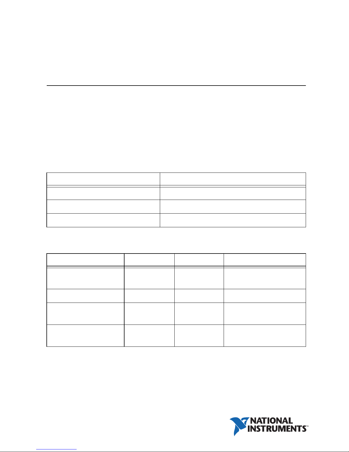
There are two single-phase and two three-phase PDUs. The following tables provide
environmental ratings and feature information.
Table 1. RMX-10050/10051 Environmental Ratings (All Models)
Category Rating
Operational Maximum Altitude 3000 m
Operational Temperature Range 0 °C to 50 °C
Operational Humidity Range 5% to 85% relative humidity, noncondensing
Table 2. RMX PDU Family and Features
Product Model Part Number Included Features
Single Phase PDU
with DC Output
Single Phase PDU RMX-10050 (785342-01) Remote EPO
Three Phase PDU (Wye) RMX-10051 (785344-01) DC Output, Remote EPO,
Three Phase PDU (Delta) RMX-10051 (785343-01) DC Output, Remote EPO,
RMX-10050 (785341-01) DC Output, Remote EPO,
Sequencing
Sequencing
Sequencing
Page 2
The AC output voltages provided by each PDU are based on the mains voltage and the specific
configuration. AC output ratings are also affected by the specific configuration.
Table 3. RMX-10050/10051 Input and AC Output Ratings
Product
RMX-10050
(785341-01)
Single Phase
with DC Output
RMX-10050
(785342-01)
Single Phase
RMX-10051
(785344-01)
Three Phase
Wye 4P5W
RMX-10051
(785343-01)
Three Phase
Delta 3P4W
Mains Inlet
Connector
IEC 60320 C20 100-240 V~
IEC 60320 C20 100-240 V~
IEC 60309
ABL Sursum
S51S30
IEC 60309
ABL Sursum
S51S30
Mains Inlet
Rating
2P3W 16A
50/60 Hz
2P3W 16A
50/60 Hz
220/380240/415 V~ L-L
4P5W 16A
50/60 Hz
200-208 V~ L-L
3P4W 16A
50/60 Hz
AC Output Ratings
C13: 100-240V~, 10 A max per receptacle
Total AC output:
8.7 A max with DC fully loaded,
16 A max with DC disabled
C13: 100-240V~, 10 A max per receptacle
Total AC output: 16 A max
C13: 220-240 V~, 10 A max per receptacle
C19: 220-240 V~, 16 A max per receptacle
Total AC output
Group J3: 16 A max
Group J2: 16 A max
Group J1: 12.7 A max with DC fully loaded,
16 A max with DC disabled
C13: 200-208 V~, 10 A max per receptacle
C19: 200-208 V~, 12.8 A max per receptacle
Total AC output with balanced load
Group J3: 9.2 A max
Group J2: 9.2 A max
Group J1: 5.6 A max with DC fully loaded,
9.2 A max with DC disabled
Note For the RMX-10051 (785344-01), the neutral pin in the inlet connector is not used.
2 | ni.com | RMX-10050/10051 User Guide
Page 3
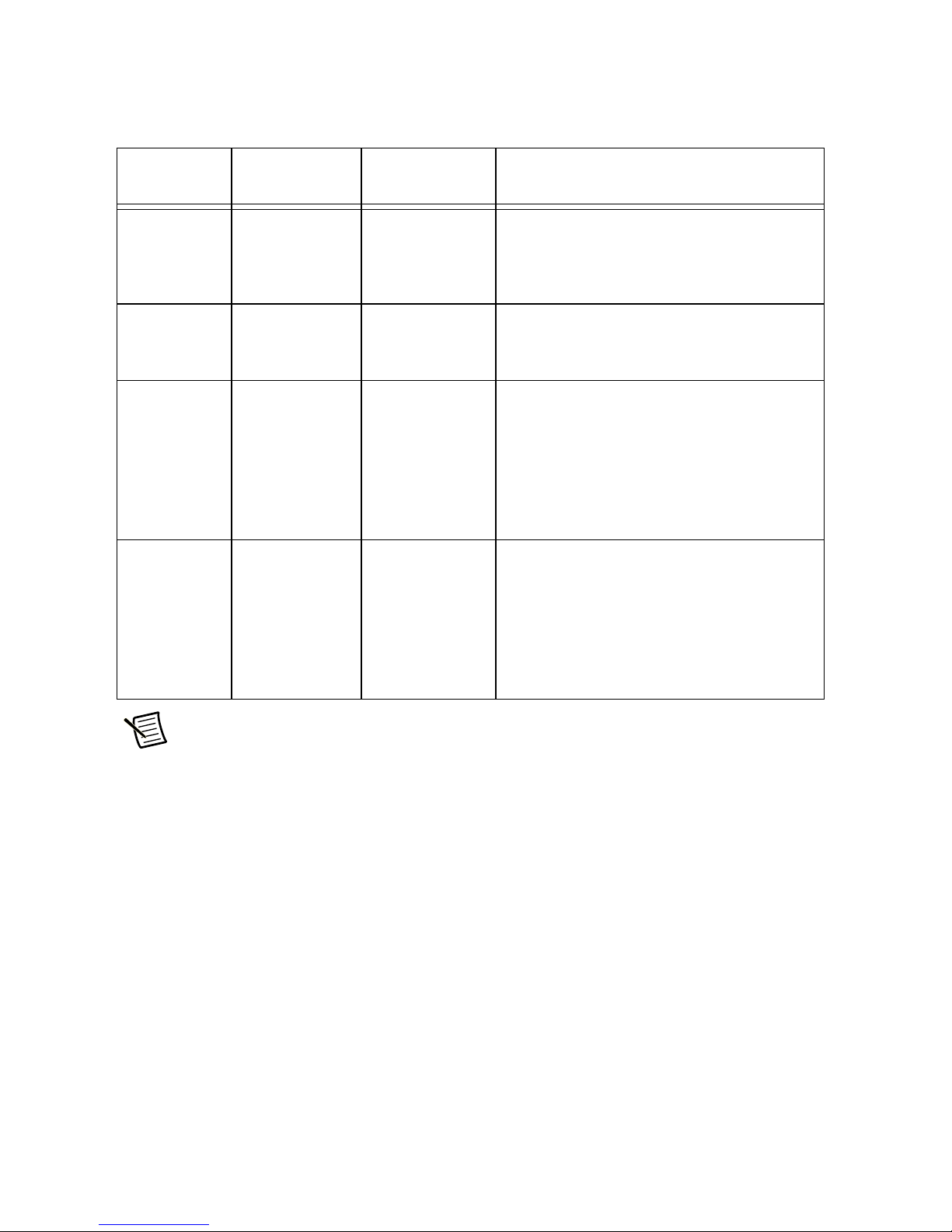
When the DC output feature is included, it draws power from the AC mains, and affects the
available AC Output power. DC output ratings are shown in the following table.
Table 4. RMX-10050/10051 Family DC Output Ratings
DC
Channel
Power
Capacity
Voltage
RMX-10050
(785341-01)
Output
Rating
RMX-10051
(785344-01)
Output
Rating
RMX-10051
(785343-01)
Output
Rating
DC1 125 W 12 VDC 10.4 A max 12.5 A max 12.5 A max
DC2 125 W 24 VDC 5.2 A max 6.25 A max 6.25 A max
DC3 125 W 24 VDC 5.2 A max 6.25 A max 6.25 A max
DC4 125 W 48 VDC 2.6 A max 3.13 A max 3.13 A max
Note All models, except the RMX-10050 (785342-01), include a DC output
feature. The total DC Output is always limited to 500 W. This is divided evenly as
125 W per each of the four output channels.
Safety
• This product is intended for indoor use only and should not be exposed to excess moisture.
• This product is intended for installation in a restricted access location by a skilled person.
• This product is intended for use by an instructed person.
• This product is classified as pluggable equipment. The mains inlet plug serves as the
disconnect device. The mains inlet plug shall be installed so that it is easily accessible.
• This product is equipped with a safety ground connection through the mains inlet plug,
as well as a redundant chassis ground screw on the rear panel. Ensure that the product is
properly grounded before applying power.
• Disconnect all power to the product prior to servicing.
• Do no open this product as it contains no user serviceable parts inside. All service concerns
should be directed to National Instruments.
• The ratings for all output receptacles are marked on the top cover of the chassis. Be sure to
observe the ratings for all connected load equipment.
• If this product is used in a manner which does not comply with this instruction manual,
the protection provided by the equipment may be impaired.
Hot Surface Contact with the top cover of chassis may cause burns. Ensure the
unit has cooled prior to handling.
RMX-10050/10051 User Guide | © National Instruments | 3
Page 4

Installation
Mounting
This product is designed for mounting in an EIA-310 compliant 19 in. rack. It includes
adjustable rack ears for mounting in either a flush or recessed configuration. The user is
responsible for ensuring the mounting method provides adequate structural support for the
product and any attached cables. Ensure the product is securely mounted before applying power.
Ventilation
The user is responsible for ensuring the mounting location provides adequate ventilation to
dissipate heat generated during operation of the product. Some models include an air intake on
the front panel and an exhaust fan on the rear panel. Ensure no external equipment or cables
restrict the airflow through the intake or exhaust ports.
Chassis Ground
The rear of the chassis includes a redundant chassis ground screw and ground wire. If desired
for your installation location, connect the chassis ground wire to the rack cabinet using an
appropriate fastener.
Main CB Off
Ensure the main CB on the front of the product is in the OFF position before connecting mains
power.
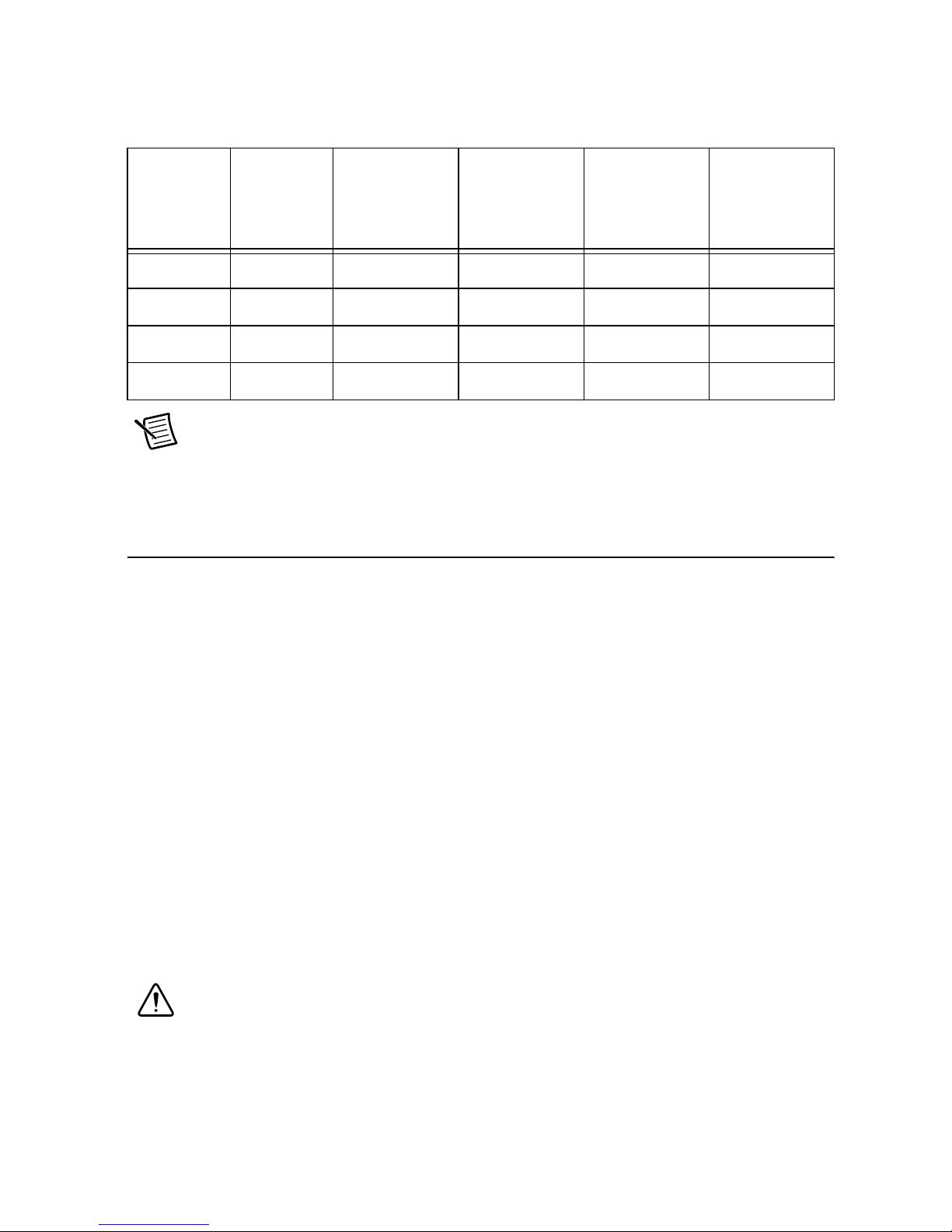
Facility Power Source
The facility power source or upstream equipment feed for this product must include an
overcurrent protective device with a maximum rating as shown in the following table.
Table 5. Required Facility or Equipment Overcurrent Protection
Related
Model (Part Number)
RMX-10050 (785341-01, 785342-01) 16 A 20 A
RMX-10051 (785344-01) 16 A 20 A
RMX-10051 (785343-01) 16 A 20 A
Continuous Current
Required
Mains Protection
4 | ni.com | RMX-10050/10051 User Guide
Page 5

Operation
1. Connect load equipment, making sure to observe the outlet ratings.
2. Turn on the main circuit breaker for the PDU.
3. Confirm that the main power indicator shows power is present.
Optional Features
Sequencing
The optional sequencing feature is used to support sequential power-up of the outlets. With this
feature, the sequenced start up begins when the remote EPO interface is used to enable the
PDU outputs. The specific start up sequence is defined in the following table.
Table 6. Sequencing Behavior
Model Step Timing Outlets Controlled
RMX-10050 (785341-01) 1 Immediate Group A, DC Outputs
2 After two seconds Group B
RMX-10051 (785344-01) 1 Immediate J1, DC Outputs
2 After two seconds J2, J3
RMX-10051 (785343-01) 1 Immediate J1, DC Outputs
2 After two seconds J2, J3
DC Output
The optional DC output feature provides four independent DC outputs via terminal blocks on the
rear panel. The total DC output is always limited to 500 W. This is divided evenly as 125 W per
each of the four output channels.
The ratings table in this manual describes the specific outputs and ratings for all models except
the RMX-10050 (785342-01). The DC output feature also includes a DC inhibit connector
which can be used to individually control each DC output channel. The connector mounted on
the rear of the PDU is Molex 39-01-2126, and the mating connector is Molex 39-01-2125.
The following table shows the DC Inhibit Connector Pinout.
RMX-10050/10051 User Guide | © National Instruments | 5
Page 6

Table 7. DC Inhibit Connector Pinout
Pin Name Description
1 PG1 Power Good Channel 1
2 INH1 Inhibit Channel 1
3 PG2 Power Good Channel 2
4 INH2 Inhibit Channel 2
5 PG3 Power Good Channel 3
6 INH3 Inhibit Channel 3
7 PG4 Power Good Channel 4
8 INH4 Inhibit Channel 4
9 GINH Global Inhibit
10 ACOK AC ains signal
11 +5 V Global 5 V bias
12 COM Common
Remote-EPO
The optional Remote-EPO feature allows external control of all outlets. The toggle switch on the
front panel selects the Remote-EPO mode.
• OFF will prevent all outlets from being powered.
• LOCAL/ON will enable power to all outlets, unless they are being disabled by the outlet
control bus.
• REMOTE will place all outlets under the control of the outlet control bus. The outlet
control bus includes three 3-pin connectors which are wired in parallel. This arrangement
allows multiple PDUs to be connected in a daisy-chain configuration and controlled from
a single control panel. The connectors mounted on the PDU are Amp/TE 1-480304-0, and
the mating connector is Amp/TE 1-480305-0. The 3-pin connectors use two low-voltage
signals as follows:
– Shorting the ENABLE pin to the RETURN pin with a dry contact will trigger the
Enable signal.
– Opening the DISABLE pin from the RETURN pin will trigger the Disable signal.
This signal is intended to be operated from a normally-closed contact on a control
switch. Note that the DISABLE pin must be shorted to the RETURN pin to allow the
switched outlets to operate, regardless of the toggle switch positions noted above.
– Note that the Disable signal has priority, so that if both signals are triggered at the same
time, the net result will be Disable.
6 | ni.com | RMX-10050/10051 User Guide
Page 7

Figure 1. RMX-10050 Dimensions
438.912 mm
(17.28 in.
)
Front View
Rear View
Side View
63.50 mm
(2.50 in.
)
63.50 mm
(2.50 in.
)
63.50 mm
(2.50 in.
)
303.02 mm
(11.93 in.)
19.30 mm
(0.76 in.
)
20.066 mm
(0.79 in.
)
482.60 mm
(19.00 in.
)
44.196 mm
(1.74 in.
)
Black #27038
All Outside Surfaces
Exhaust Air
#4–4 X 0.20 DP Holes
2X Both Sides
OffOff OnOn
BreakerBreaker
Main BreakerMain Breaker
GROUP AGROUP A
OnOn
Main PowerMain Power
PoweredPowered ControlControl
ControlControl
Switched OutletsSwitched OutletsSwitched OutletsSwitched Outlets Outlet Control BusOutlet Control Bus
Local/OnLocal/On
OffOff
A
Remote
Remote
DC 1DC 1
+ – + – + – + –
DC 1
DC 1 DC 1DC 1 DC 1DC 1
GROUP AGROUP A
GROUP BGROUP B
DC INHIBITDC INHIBIT
EnableEnable
DisableDisable
ReturnReturn
Note DC outputs and DC Inhibit Bus are not available on the
RMX-10050 (785342-01).
RMX-10050/10051 User Guide | © National Instruments | 7
Page 8

Figure 2. RMX-10051 Dimensions
Front View
486.60 mm
(
19. 00 in.)
88.14 mm
(
3.47 in.) 2U
ONONON
438.658 mm
(
17.27 in.)
Black #27038
All Outside Surfaces
Rear View
Side View
63.50 mm
(2.50 in.
)
63.50 mm
(2.50 in.
)
63.50 mm
(2.50 in.
)
309.118 mm
(12.17 in.
)
19.30 mm
(0.76 in.
)
38.862 mm
(1.53 in.
)
259.08 cm
(8.5 ft.
)
Harmonized Cord
#4–4 X 0.20 DP Holes
3X Both Sides
IEC 60309 6H
Exhaust Air
Main BreakerMain Breaker
DC INHIBITDC INHIBIT
J 8J 8
DC 1DC 1
+ – + – + – + –
DC 2
DC 2 DC 3DC 3 DC 4DC 4
J 3 - 2J 3 - 2
J 3 - 1J 3 - 1
J 2 - 2J 2 - 2
J 2 - 1J 2 - 1
J 1 - 2J 1 - 2
J 1 - 1J 1 - 1 InletInlet
J 7J 7 J 6J 6
CB 1CB 1 CB 2CB 2 CB 3CB 3
J 4J 4 J 5J 5
BreakerBreaker
EnableEnable
DisableDisable
ReturnReturn
PoweredPowered ControlControl
ControlControl Switched OutletsSwitched Outlets
Local/OnLocal/On
OffOff
RemoteRemote
A
B
C
EnableEnable
DisableDisable
ReturnReturn
8 | ni.com | RMX-10050/10051 User Guide
Page 9

Worldwide Support and Services
The NI website is your complete resource for technical support. At ni.com/support you have
access to everything from troubleshooting and application development self-help resources to
email and phone assistance from NI Application Engineers.
ni.com/services for NI Factory Installation Services, repairs, extended warranty, and
Visit
other services.
ni.com/register to register your NI product. Product registration facilitates technical
Visit
support and ensures that you receive important information updates from NI.
A Declaration of Conformity (DoC) is our claim of compliance with the Council of the European
Communities using the manufacturer’s declaration of conformity. This system affords the user
protection for electromagnetic compatibility (EMC) and product safety. You can obtain the DoC
for your product by visiting
you can obtain the calibration certificate for your product at ni.com/calibration.
NI corporate headquarters is located at 11500 North Mopac Expressway, Austin, Texas,
78759-3504. NI also has offices located around the world. For telephone support in the United
States, create your service request at
For telephone support outside the United States, visit the Worldwide Offices section of
ni.com/niglobal to access the branch office websites, which provide up-to-date contact
information, support phone numbers, email addresses, and current events.
ni.com/certification. If your product supports calibration,
ni.com/support or dial 1 866 ASK MYNI (275 6964).
RMX-10050/10051 User Guide | © National Instruments | 9
Page 10

Information is subject to change without notice. Refer to the NI Trademarks and Logo Guidelines at ni.com/trademarks for more information
on NI trademarks. Other product and company names mentioned herein are trademarks or trade names of their respective companies. For patents
covering NI products/technology, refer to the appropriate location: Help»Patents in your software, the patents.txt file on your media, or the
National Instruments Patents Notice at ni.com/patents. You can find information about end-user license agreements (EULAs) and third-party
legal notices in the readme file for your NI product. Refer to the Export Compliance Information at ni.com/legal/export-compliance
for the NI global trade compliance policy and how to obtain relevant HTS codes, ECCNs, and other import/export data. NI MAKES NO EXPRESS OR
IMPLIED WARRANTIES AS TO THE ACCURACY OF THE INFORMATION CONTAINED HEREIN AND SHALL NOT BE LIABLE FOR ANY ERRORS. U.S.
Government Customers: The data contained in this manual was developed at private expense and is subject to the applicable limited rights and
restricted data rights as set forth in FAR 52.227-14, DFAR 252.227-7014, and DFAR 252.227-7015.
© 2017-2018 National Instruments. All rights reserved.
376892B-01 Jul18
 Loading...