

Page 1

RMC-8357
User Manual
RMC-8357 User Manual
September 2017
377265A-01
Page 2

Support
Worldwide Technical Support and Product Information
ni.com
Worldwide Offices
Visit ni.com/niglobal to access the branch office websites, which provide up-to-date
contact information, support phone numbers, email addresses, and current events.
National Instruments Corporate Headquarters
11500 North Mopac Expressway Austin, Texas 78759-3504 USA Tel: 512 683 0100
For further support information, refer to the NI Services appendix. To comment on NI
documentation, refer to the NI website at ni.com/info and enter the Info Code feedback.
© 2017 National Instruments. All rights reserved.
Page 3

Legal Information
Limited Warranty
This document is provided ‘as is’ and is subject to being changed, without notice, in future editions. For the latest version,
ni.com/manuals. NI reviews this document carefully for technical accuracy; however, NI MAKES NO EXPRESS
refer to
OR IMPLIED WARRANTIES AS TO THE ACCURACY OF THE INFORMATION CONTAINED HEREIN AND
SHALL NOT BE LIABLE FOR ANY ERRORS.
NI warrants that its hardware products will be free of defects in materials and workmanship that cause the product to fail to
substantially conform to the applicable NI published specifications for one (1) year from the date of invoice.
For a period of ninety (90) days from the date of invoice, NI warrants that (i) its software products will perform substantially
in accordance with the applicable documentation provided with the software and (ii) the software media will be free from
defects in materials and workmanship.
If NI receives notice of a defect or non-conformance during the applicable warranty period, NI will, in its discretion: (i) repair
or replace the affected product, or (ii) refund the fees paid for the affected product. Repaired or replaced Hardware will be
warranted for the remainder of the original warranty period or ninety (90) days, whichever is longer. If NI elects to repair or
replace the product, NI may use new or refurbished parts or products that are equivalent to new in performance and reliability
and are at least functionally equivalent to the original part or product.
You must obtain an RMA number from NI before returning any product to NI. NI reserves the right to charge a fee for
examining and testing Hardware not covered by the Limited Warranty.
This Limited Warranty does not apply if the defect of the product resulted from improper or inadequate maintenance,
installation, repair, or calibration (performed by a party other than NI); unauthorized modification; improper environment;
use of an improper hardware or software key; improper use or operation outside of the specification for the product; improper
voltages; accident, abuse, or neglect; or a hazard such as lightning, flood, or other act of nature.
THE REMEDIES SET FORTH ABOVE ARE EXCLUSIVE AND THE CUSTOMER’S SOLE REMEDIES, AND SHALL
APPLY EVEN IF SUCH REMEDIES FAIL OF THEIR ESSENTIAL PURPOSE.
EXCEPT AS EXPRESSLY SET FORTH HEREI N, PRODUCTS ARE PROVIDED "AS IS" WITHOUT WARRANTY OF
ANY KIND AND NI DISCLAIMS ALL WARRANTIES, EXPRESSED OR IMPLIED, WITH RESPECT TO THE
PRODUCTS, INCLUDING ANY IMPLIED WARRANTIES OF MERCHANTABILITY, FITNESS FOR A
PARTICULAR PURPOSE, TITLE OR NON-INFRINGEMENT, AND ANY WARRANTIES THAT MAY ARISE FROM
USAGE OF TRADE OR COURSE OF DEALING. NI DOES NOT WARRANT, GUARANTEE, OR MAKE ANY
REPRESENTATIONS REGARDING THE USE OF OR THE RESULTS OF THE USE OF THE PRODUCTS IN TERMS
OF CORRECTNESS, ACCURACY, RELIABILITY, OR OTHERWISE. NI DOES NOT WARRANT THAT THE
OPERATION OF THE PRODUCTS WILL BE UNINTERRUPTED OR ERROR FREE.
In the event that you and NI have a separate signed written agreement with warranty terms covering the products, then the
warranty terms in the separate agreement shall control.
Copyright
Under the copyright laws, this publication may not be reproduced or transmitted in any form, electronic or mechanical,
including photocopying, recording, storing in an information retrieval system, or translating, in whole or in part, without the
prior written consent of National Instruments Corporation.
National Instruments respects the intellectual property of others, and we ask our users to do the same. NI software is protected
by copyright and other intellectual property laws. Where NI software may be used to reproduce software or other materials
belonging to others, you may use NI software only to reproduce materials that you may reproduce in accordance with the
terms of any applicable license or other legal restriction.
End-User License Agreements and Third-Party Legal Notices
You can find end-user license agreements (EULAs) and third-party legal notices in the following locations:
• Notices are located in the
directories.
• EULAs are located in the
•Review
<National Instruments>\_Legal Information.txt for information on including legal information in
installers built with NI products.
U.S. Government Restricted Rights
If you are an agency, department, or other entity of the United States Government (“Government”), the use, duplication,
reproduction, release, modification, disclosure or transfer of the technical data included in this manual is governed by the
Restricted Rights provisions under Federal Acquisition Regulation 52.227-14 for civilian agencies and Defense Federal
Acquisition Regulation Supplement Section 252.227-7014 and 252.227-7015 for military agencies.
Trademarks
Refer to the NI Trademarks and Logo Guidelines at ni.com/trademarks for more information on NI trademarks.
ARM, Keil, and µVision are trademarks or registered of ARM Ltd or its subsidiaries.
LEGO, the LEGO logo, WEDO, and MINDSTORMS are trademarks of the LEGO Group.
TETRIX by Pitsco is a trademark of Pitsco, Inc.
FIELDBUS FOUNDATION
®
EtherCAT
is a registered trademark of and licensed by Beckhoff Automation GmbH.
<National Instruments>\_Legal Information and <National Instruments>
<National Instruments>\Shared\MDF\Legal\license directory.
™
and FOUNDATION™ are trademarks of the Fieldbus Foundation.
Page 4

CANopen® is a registered Community Trademark of CAN in Automation e.V.
™
DeviceNet
Go!, SensorDAQ, and Vernier are registered trademarks of Vernier Software & Technol ogy. Vernier Software & Technology
and
and EtherNet/IP™ are trademarks of ODVA.
vernier.com are trademarks or trade dress.
Xilinx is the registered trademark of Xilinx, Inc.
Taptite and Trilobular are registered trademarks of Research Engineering & Manufacturing Inc.
®
is the registered trademark of Apple Inc.
FireWire
®
Linux
is the registered trademark of Linus Torvalds in the U.S. and other countries.
Handle Graphics
Simulink Coder
Tektronix
The Bluetooth
The ExpressCard
license.
The mark LabWindows is used under a license from Microsoft Corporation. Windows is a registered trademark of Microsoft
Corporation in the United States and other countries.
®
, MATLAB®, Simulink®, Stateflow®, and xPC TargetBox® are registered trademarks, and
™
, TargetBox™, and Target Language Compiler™ are trademarks of The MathWorks, Inc.
®
, Tek, and Tektronix, Enabling Technology are registered trademarks of Tektronix, Inc.
®
word mark is a registered trademark owned by the Bluetooth SIG, Inc.
™
word mark and logos are owned by PCMCIA and any use of such marks by National Instruments is under
Other product and company names mentioned herein are trademarks or trade names of their respective companies.
Members of the National Instruments Alliance Partner Program are business entities independent from NI and have no
agency, partnership, or joint-venture relationship with NI.
Patents
For patents covering NI products/technology, refer to the appropriate location: Help»Patents in your software,
the patents.txt file on your media, or the National Instruments Patent Notice at ni.com/patents.
Export Compliance Information
Refer to the Export Compliance Information at ni.com/legal/export-compliance for the NI global trade compliance
policy and how to obtain relevant HTS codes, ECCNs, and other import/export data.
WARNING REGARDING USE OF NATIONAL INSTRUMENTS PRODUCTS
YOU ARE ULTIMATELY RESPONSIBLE FOR VERIFYING AND VALIDATING THE SUITABILITY AND
RELIABILITY OF THE PRODUCTS WHENEVER THE PRODUCTS ARE INCORPORATED IN YOUR SYSTEM OR
APPLICATION, INCLUDING THE APPROPRIATE DESIGN, PROCESS, AND SAFETY LEVEL OF SUCH SYSTEM
OR APPLICATION.
PRODUCTS ARE NOT DESIGNED, MANUFACTURED, OR TESTED FOR USE IN LIFE OR SAFETY CRITICAL
SYSTEMS, HAZARDOUS ENVIRONMENTS OR ANY OTHER ENVIRONMENTS REQUIRING FAIL-SAFE
PERFORMANCE, INCLUDING IN THE OPERATION OF NUCLEAR FACILITIES; AIRCRAFT NAVIGATION; AIR
TRAFFIC CONTROL SYSTEMS; LIFE SAVING OR LIFE SUSTAINING SYSTEMS OR SUCH OTHER MEDICAL
DEVICES; OR ANY OTHER APPLICATION IN WHICH THE FAILURE OF THE PRODUCT OR SERVICE COULD
LEAD TO DEATH, PERSONAL INJURY, SEVERE PROPERTY DAMAGE OR ENVIRONMENTAL HARM
(COLLECTIVELY, “HIGH-RISK USES”). FURTHER, PRUDENT STEPS MUST BE TAKEN TO PROTECT AGAINST
FAILURES, INCLUDING PROVIDING BACK-UP AND SHUT-DOWN MECHANISMS. NI EXPRESSLY DISCLAIMS
ANY EXPRESS OR IMPLIED WARRANTY OF FITNESS OF THE PRODUCTS OR SERVICES FOR HIGH-RISK
USES.
Page 5

Contents
About This Manual
Related Documentation .................................................................................................... xiii
Chapter 1
Getting Started
Unpacking......................................................................................................................... 1-1
What You Need to Get Started ......................................................................................... 1-1
RMC-8357 Overview ....................................................................................................... 1-2
Key Features ..................................................................................................................... 1-2
Mainboard Features .................................................................................................. 1-2
CPU .................................................................................................................. 1-2
Memory ............................................................................................................ 1-2
Slots .................................................................................................................. 1-2
Video ................................................................................................................ 1-2
HDD.................................................................................................................. 1-2
Blu-ray .............................................................................................................. 1-3
Onboard LAN ................................................................................................... 1-3
Onboard I/O...................................................................................................... 1-3
Power Supply.................................................................................................... 1-3
Power Management Features............................................................................ 1-3
Front Panel LEDs ............................................................................................. 1-3
System Management......................................................................................... 1-3
RMC-8357 Description .................................................................................................... 1-4
Chapter 2
Installation and BIOS Setup
Safety Information ............................................................................................................ 2-1
Chassis Cooling Considerations ....................................................................................... 2-2
Providing Adequate Clearance ................................................................................. 2-2
Installation ........................................................................................................................ 2-2
Connecting Safety Ground ............................................................................................... 2-3
Connecting to Power Source ............................................................................................ 2-3
BIOS Setup ....................................................................................................................... 2-3
Starting the BIOS Setup Utility ................................................................................ 2-4
How to Change the Configuration Data ........................................................... 2-4
How to Start the Setup Utility .......................................................................... 2-4
Main Setup........................................................................................................................ 2-5
System Date/System Time................................................................................ 2-5
BIOS Version ................................................................................................... 2-5
Build Date......................................................................................................... 2-5
© National Instruments | v
Page 6

Contents
Memory Information.................................................................................................2-5
Total Memory ................................................................................................... 2-5
Memory Speed ..................................................................................................2-5
Advanced Setup Configurations ....................................................................................... 2-5
Boot Feature.............................................................................................................. 2-6
Quiet Boot......................................................................................................... 2-6
AddOn ROM Display Mode............................................................................. 2-6
Bootup NumLock State .................................................................................... 2-6
Wait For F1 If Error.......................................................................................... 2-6
INT19 (Interrupt 19) Trap Response ................................................................2-6
Re-try Boot ....................................................................................................... 2-6
Power Configuration................................................................................................. 2-6
DeepSx Power Policies ..................................................................................... 2-6
Watch Dog Function ......................................................................................... 2-7
Power Button Function ..................................................................................... 2-7
Restore on AC Power Loss............................................................................... 2-7
Chipset Configuration............................................................................................... 2-7
CPU Configuration ........................................................................................... 2-7
Clock Spread Spectrum .................................................................................... 2-8
Hyper-Threading............................................................................................... 2-8
Performance/Watt ............................................................................................. 2-8
Execute Disable Bit .......................................................................................... 2-8
PPIN Control..................................................................................................... 2-8
Hardware Prefetcher ........................................................................................ 2-8
Adjacent Cache Line Prefetch .......................................................................... 2-8
DCU Streamer Prefetcher ................................................................................. 2-9
DCU IP Prefetcher ............................................................................................ 2-9
DCU (Data Cache Unit) Mode ......................................................................... 2-9
Direct Cache Access (DCA) .............................................................................2-9
DCA Prefetch Delay ......................................................................................... 2-9
X2APIC (Extended Advanced Programmable Interrupt Controller) ............... 2-9
AES-NI ............................................................................................................. 2-9
Intel Virtualization Technology........................................................................ 2-10
Advanced Power Management Configuration.......................................................... 2-10
Power Technology ............................................................................................ 2-10
Config TDP...................................................................................................... 2-10
CPU P State Control .................................................................................................2-10
EIST (P-State)................................................................................................... 2-10
Turbo Mode ...................................................................................................... 2-10
P-state Coordination ......................................................................................... 2-10
CPU C State Control................................................................................................. 2-10
CPU C3 Report ................................................................................................. 2-11
CPU C6 Report ................................................................................................. 2-11
Enhanced Halt State (C1E) ............................................................................... 2-11
vi | ni.com
Page 7

RMC-8357 User Manual
CPU T State Control................................................................................................. 2-11
ACPI (Advanced Configuration Power Interface) T-States ............................. 2-11
Socket RAPL (Running Average Power Limit) Configuration................................ 2-11
FAST-RAPL-NSTRIKE-PL2-DUTY-CYCLE ................................................ 2-11
Turbo Power Limit Lock .................................................................................. 2-11
Long Power Limit Override ............................................................................. 2-11
Long Duration Power Limit ............................................................................. 2-11
Package Clamping Limit1 ................................................................................ 2-12
Short Duration Power Limit Enable ................................................................. 2-12
Short Duration Power Limit ............................................................................. 2-12
Package Clamping Limit2 ................................................................................ 2-12
Chipset Configuration....................................................................................................... 2-12
North Bridge ............................................................................................................. 2-12
IIO Configuration ..................................................................................................... 2-12
EV DFX (Device Function On-Hide) Feature.................................................. 2-12
IIO1 Configuration/IIO2 Configuration ........................................................... 2-12
IOAT Configuration ................................................................................................. 2-13
Enable I/OAT ................................................................................................... 2-13
No Snoop .......................................................................................................... 2-13
Relaxed Ordering.............................................................................................. 2-13
Intel VT for Directed I/O (VT-d) ............................................................................. 2-14
Interrupt Remapping......................................................................................... 2-14
Coherency Support (Non-Isoch)....................................................................... 2-14
Coherency Support (Isoch)............................................................................... 2-14
QPI (Quick Path Interconnect) Configuration.......................................................... 2-14
QPI Status ......................................................................................................... 2-14
Link Speed Mode.............................................................................................. 2-14
Link Frequency Select ...................................................................................... 2-14
Link L0p Enable ............................................................................................... 2-15
Link L1 Enable ................................................................................................. 2-15
Isoc Mode ......................................................................................................... 2-15
Memory Configuration ............................................................................................. 2-15
Enforce POR..................................................................................................... 2-15
Memory Frequency........................................................................................... 2-15
ECC Support..................................................................................................... 2-15
Data Scrambling ............................................................................................... 2-15
Enable ADR...................................................................................................... 2-15
DRAM RAPL (Running Average Power Limit) Baseline ............................... 2-15
Set Throttling Mode.......................................................................................... 2-16
Socket Interleave Below 4GB .......................................................................... 2-16
Channel Interleaving......................................................................................... 2-16
Rank Interleaving ............................................................................................. 2-16
A7 Mode ........................................................................................................... 2-16
DIMM Information................................................................................................... 2-16
© National Instruments | vii
Page 8

Contents
Memory RAS (Reliability_Availability_Serviceability) Configuration................... 2-16
RAS Mode ........................................................................................................ 2-16
Lockstep x4 DIMMs ......................................................................................... 2-17
Memory Rank Sparing...................................................................................... 2-17
Patrol Scrub....................................................................................................... 2-17
Patrol Scrub Interval ......................................................................................... 2-17
Demand Scrub................................................................................................... 2-17
Device Tagging................................................................................................. 2-17
South Bridge ............................................................................................................. 2-17
Legacy USB Support ........................................................................................2-17
XHCI Hand-Off ................................................................................................ 2-18
EHCI Hand-Off................................................................................................. 2-18
USB Mass Storage Driver Support................................................................... 2-18
Port 60/64 Emulation ........................................................................................ 2-18
USB 3.0 Support ...............................................................................................2-18
EHCI1 ............................................................................................................... 2-18
EHCI2 ............................................................................................................... 2-18
XHCI Pre-Boot Drive ....................................................................................... 2-18
XHCI Idle L1 .................................................................................................... 2-18
PCH DMI ASPM ..............................................................................................2-18
SATA Configuration.................................................................................................2-19
SATA Controller............................................................................................... 2-19
Configure SATA as .......................................................................................... 2-19
sSATA Configuration ............................................................................................... 2-21
sSATA Controller ............................................................................................. 2-21
Configure sSATA as......................................................................................... 2-21
Server ME (Management Engine) Configuration ..................................................... 2-23
PCIe/PCI/PnP Configuration ....................................................................................2-23
PCI AER (Advanced Error-Reporting) Support ............................................... 2-23
VGA Palette Snoop........................................................................................... 2-23
PERR# Generation Support..............................................................................2-23
SERR# Generation Support..............................................................................2-24
Above 4G Decoding .........................................................................................2-24
SR-IOV Support .............................................................................................. 2-24
Maximum Payload ............................................................................................2-24
Maximum Read Request...................................................................................2-24
ASPM Support..................................................................................................2-24
MMIOHBase .................................................................................................... 2-24
MMIO High Size .............................................................................................. 2-24
Onboard LAN OPROM .................................................................................... 2-25
VGA Priority..................................................................................................... 2-25
w
ork Stack...................................................................................................2-25
Net
Ipv6 PXE Support ............................................................................................ 2-25
viii | ni.com
Page 9

RMC-8357 User Manual
Super IO Configuration ............................................................................................ 2-25
Serial Port 1 Configuration/Serial Port 2 Configuration ................................. 2-25
Device Settings ................................................................................................. 2-25
Change Port 1 Settings/Change Port 2 Settings................................................ 2-25
Serial Port 2 Attribute....................................................................................... 2-26
Serial Port Console Redirection ............................................................................... 2-26
COM 1 Console Redirection ............................................................................ 2-26
COM1 Console Redirection ..................................................................................... 2-26
SOL/COM2 Console Redirection............................................................................. 2-28
SOL/COM2 Console Redirection Settings ............................................................... 2-28
EMS Console Redirection Settings .......................................................................... 2-30
Trusted Computing ................................................................................................... 2-30
Configuration.................................................................................................... 2-30
ACPI Settings ........................................................................................................... 2-31
WHEA Support................................................................................................. 2-31
Event Logs........................................................................................................................ 2-31
Change SMBIOS Event Log Settings ...................................................................... 2-31
Enabling/Disabling Options ............................................................................. 2-31
SMBIOS Event Log.......................................................................................... 2-31
Runtime Error Logging Support....................................................................... 2-31
Memory Corrected Error Enabling ................................................................... 2-32
PCI-Ex (PCI-Express) Error Enable................................................................. 2-32
Memory Correctable Error Threshold .............................................................. 2-32
Erasing Settings ................................................................................................ 2-32
SMBIOS Event Log Standard Settings ............................................................ 2-32
IPMI.................................................................................................................................. 2-33
IPMI Firmware Revision .................................................................................. 2-33
IPMI Status ....................................................................................................... 2-33
System Event Log..................................................................................................... 2-33
Enabling/Disabling Options ............................................................................. 2-33
Erasing Settings ................................................................................................ 2-33
BMC Network Configuration ................................................................................... 2-33
IPMI LAN Selection......................................................................................... 2-33
IPMI Network Link Status ............................................................................... 2-33
Update IPMI LAN Configuration..................................................................... 2-34
Configuration Address Source.......................................................................... 2-34
Security Settings ...............................................................................................................2-34
Password Check................................................................................................ 2-34
Administrator Password ................................................................................... 2-34
Secure Boot Menu ............................................................................................ 2-35
Boot Settings..................................................................................................................... 2-35
Setup Prompt Timeout...................................................................................... 2-35
Boot Mode Select ............................................................................................. 2-35
Fixed Boot Order Priorities .............................................................................. 2-35
Add New Boot Option ...................................................................................... 2-36
© National Instruments | ix
Page 10

Contents
Boot Option File Path ............................................................................................... 2-36
Create ................................................................................................................ 2-36
Delete Boot Option ........................................................................................... 2-36
Save & Exit ....................................................................................................................... 2-36
Discard Changes and Exit ................................................................................. 2-36
Save Changes and Reset ................................................................................... 2-36
Save Options .............................................................................................................2-36
Save Changes.................................................................................................... 2-36
Discard Changes ............................................................................................... 2-37
Restore Defaults................................................................................................ 2-37
Save As User Defaults ...................................................................................... 2-37
Restore User Defaults ....................................................................................... 2-37
Boot Override ................................................................................................... 2-37
BIOS Error Beep Codes.................................................................................................... 2-37
OS Reinstallation and Recovery ....................................................................................... 2-38
Cleaning ............................................................................................................................ 2-39
Exterior Cleaning ...................................................................................................... 2-39
Rack Mounting ................................................................................................................. 2-39
Installing the Inner Slides ......................................................................................... 2-39
Installing the Slide Mounting Brackets in the Rack .................................................2-41
Installing the Outer Slides in the Rack ..................................................................... 2-42
Installing the Chassis into the Rack .......................................................................... 2-43
Chapter 3
I/O Information
Front Panel Connectors.....................................................................................................3-1
Rear Panel Connectors...................................................................................................... 3-1
Universal Serial Bus ................................................................................................. 3-2
Serial ......................................................................................................................... 3-3
VGA.......................................................................................................................... 3-4
Ethernet ..................................................................................................................... 3-5
MXI-Express Connectors ................................................................................................. 3-5
Chapter 4
Common Configuration Questions
General Questions............................................................................................................. 4-1
Boot Options .....................................................................................................................4-2
Chassis Configuration.......................................................................................................4-2
Chapter 5
Troubleshooting
x | ni.com
Page 11

Appendix A
Specifications
Appendix B
Hardware Configuration
Appendix C
NI Services
Glossary
Index
RMC-8357 User Manual
© National Instruments | xi
Page 12

About This Manual
The RMC-8357 User Manual contains information about installing, configuring, using, and
maintaining the RMC-8357.
Related Documentation
The following documents contain information that you may find helpful as you read this manual:
• CompactPCI Specification PICMG 2.0 R 3.0
• PXI Hardware Specification, Revision 2.1
• PXI Software Specification, Revision 2.1
• ANSI/IEEE Standard 1014-1987, IEEE Standard for a Versatile Backplane Bus: VMEbus
• ANSI/VITA 1-1994, VME64
• NI-VISA User Manual
• NI-VISA Programmer Reference Manual
• Read Me First: Safety and Electromagnetic Compatibility, National Instruments
© National Instruments | xiii
Page 13

1
Getting Started
This chapter describes the key features of the RMC-8357 and lists the kit contents and optional
equipment you can order from National Instruments.
Unpacking
Carefully inspect the shipping container and the RMC-8357 for damage. Check for visible
damage to the metal work. Check to make sure all hardware and switches are undamaged. If
damage appears to have been caused during shipment, file a claim with the carrier. Retain the
packing material for possible inspection and/or reshipment.
What You Need to Get Started
The RMC-8357 kit contains the following items:
RMC-8357 rack mount controller
RMC-8357 Installation Guide
RMC-8357 User Manual (available at ni.com/support)
Windows recovery media (not included in diskless versions)
23-36 VDC 3-pin cable (ships with the DC option)
A power cable is not included with the RMC-8357 kit. Contact National Instruments if you need
help finding a power cable.
Table 1-1. AC Power Cables
Power Cable Reference Standards
Standard 120 V (USA) ANSI C73.11/NEMA 5-15-P/IEC83
Switzerland 220 V SEV
Australia 240 V AS C112
Universal Euro 230 V CEE (7), II, IV, VII IEC83
North America 240 V ANSI C73.20/NEMA 5-15-P/IEC83
© National Instruments | 1-1
Page 14

Chapter 1 Getting Started
Table 1-1. AC Power Cables (Continued)
Power Cable Reference Standards
United Kingdom 230 V BS 1363/IEC83
Japan 100 V ANSI C73.11/NEMA 5-15-P/IEC83
RMC-8357 Overview
The RMC-8357 is a rugged 1U PC-based controller for remote control of PXI chassis. The
controller provides leading-edge processing power with Intel Xeon E5-2620 v4 processors, high
disk bandwidth with software RAID support, high I/O bandwidth with two PCI Express 3.0 x16
slots, and up to 32 GB of memory.
Key Features
The RMC-8357 offers the performance of a high-end PC in a compact 1U rack-mountable form
factor for controlling a PXI or PXI Express system using a National Instruments remote
controller.
Mainboard Features
CPU
• Intel Xeon E5-2620 v4 Eight Core Processor, LGA 2011
Memory
• 32 GB DDR4 RAM
Slots
• One PCI Express 3.0 x16 slot, full height
• One PCI Express 3.0 x16 slot (requires a custom PCI Express bracket)
Note The x16 bottom slot requires a custom bracket and supports only half-height
cards.
Video
• PCIe video graphics card
HDD
• One 1 TB 2.5 in. SSD
• Supports up to four 2.5 in. drives
1-2 | ni.com
Page 15

Blu-ray
• Slim DVD-R/W Blu-ray drive
Onboard LAN
• Two Gigabit Ethernet ports
Onboard I/O
• Two Serial ports
• One DisplayPort
• One DVI port
• One VGA port (disabled by default)
• Two USB 2.0 ports (rear)
• Two USB 3.0 ports (front)
• Two USB 3.0 ports (rear)
Power Supply
• Supports redundant AC and DC power supplies
Power Management Features
• ACPI/ACPM power management
• Wake-On-LAN (WOL) header
• Power-on mode from AC power recovery
RMC-8357 User Manual
Front Panel LEDs
• Power indicator
• Power shuttle indicators
• LAN status indicators
• HDD indicator
• System temp (overheat) and fan (fail) warning indicator
System Management
• Monitoring for CPU and chassis environment
• CPU thermal trip support
• +5 V standby alert LED
• Fan speed control
© National Instruments | 1-3
Page 16
Chapter 1 Getting Started
Rugged Rackmount ControllerRugged Rackmount Controller
NI RMC-8357NI RMC-8357
4
4
32
12
9876
5 10
11
1
RMC-8357 Description
Figures 1-1 1-2 and shows the key features of the RMC-8357 front and rear panels. For detailed
information about the RMC-8357 front and rear panel, refer to Chapter 3, I/O Information.
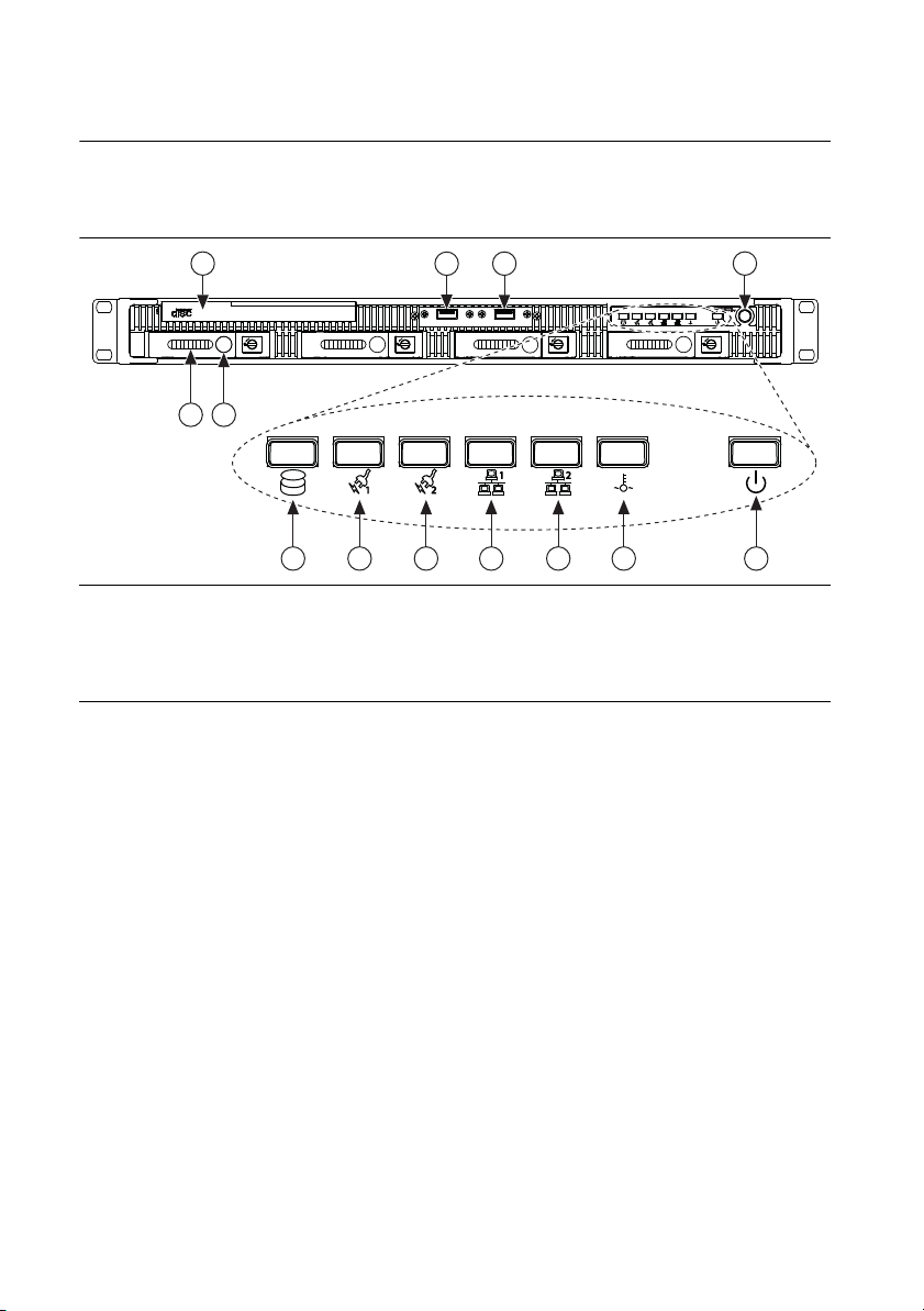
Figure 1-1. Front View of the RMC-8357
1 DVD-R/W Blu-ray Drive
2 Hard Drives
3 Hard Drive Ejector Buttons
4USB Ports
5 Hard Drive Activity Indicator
6 Power Shuttle 1 Indicator
7 Power Shuttle 2 Indicator
8 LAN1 Status Indicator
9 LAN2 Status Indicator
10 System Temp and Fan Warning Indicator
11 Power Indicator
12 Power Button
The front panel includes the following LEDs:
• Hard drive activity indicator—Glows when there is hard drive activity.
• Power shuttle indicators—Glow when power shuttles are powered on.
• LAN status indicators—Flash when there is activity on LAN1 or LAN2.
• Overheat/fan fail indicator
– Off—Normal
– On—Overheat
– Flashing—Fan failure warning
• Power indicator—Glows when the RMC-8357 is powered on.
1-4 | ni.com
Page 17

RMC-8357 User Manual
Figure 1-2. Rear View of the RMC-8357
1 2 3
11 10 9 8 7 6 5 4
1 IPMI Management Port
2DVI Port
3DisplayPort
4 MXI x1 Ports
5 UID Switch
6 VGA Port (Disabled By Default)
7 LAN Ports
8 USB 3.0 Ports
9 USB 2.0 Ports
10 Serial Ports
11 Power Connector
© National Instruments | 1-5
Page 18

2
Installation and BIOS Setup
This chapter describes how to install, configure, and use the RMC-8357. Read this chapter
before connecting the RMC-8357 to a power source.
Safety Information
Caution Before undertaking any troubleshooting, maintenance, or exploratory
procedure, carefully read the following caution notices.
Caution Product functionality can be disrupted if the knurled thumbscrews on the
back of the top cover are subjected to Electrostatic Discharge (ESD). To prevent
damage, you must employ industry-standard ESD prevention measures during
installation, maintenance, and operation.
Caution Overloading the circuits may damage supply wiring. Do not exceed the
ratings on the equipment nameplate when connecting equipment to the supply circuit.
Note Tighten the thumbscrew for the top panel cover with a tool after both initial
installation and subsequent access.
Caution To avoid risk of explosion, do not replace the battery (JBAT1) with an
incorrect battery type. Dispose of used batteries according to the battery instructions.
This equipment contains voltage hazardous to human life and safety, and is capable of inflicting
personal injury.
• Chassis Grounding—The RMC-8357 requires a connection from the premise wire safety
ground to the RMC-8357 chassis ground. The earth safety ground must be connected during
use of this equipment to minimize shock hazards. Refer to the Connecting Safety Ground
section for instructions on connecting safety ground.
• Mechanical Loading—To avoid a hazardous load condition, be sure the mechanical load
is even when rack mounting the equipment.
• Live Circuits—Operating personnel and service personnel must not remove protective
covers when operating or servicing the RMC-8357. Adjustments and service to internal
components must be undertaken by qualified service technicians. During service of
this product, the mains connector to the premise wiring must be disconnected. Dangerous
voltages may be present under certain conditions; use extreme caution.
© National Instruments | 2-1
Page 19

Chapter 2 Installation and BIOS Setup
• Explosive Atmosphere—Do not operate the chassis in conditions where flammable gases
are present. Under such conditions, this equipment is unsafe and may ignite the gases or gas
fumes.
• Parts Replacement—Service this equipment only with parts that are exact replacements,
both electrically and mechanically. Contact National Instruments for replacement part
information. Installation of parts with those that are not direct replacements may cause
harm to personnel operating the chassis. Furthermore, damage or fire may occur if
replacement parts are unsuitable.
• Modification—Do not modify any part of the RMC-8357 from its original condition.
Unsuitable modifications may result in safety hazards.
Chassis Cooling Considerations
The RMC-8357 is designed to operate on a bench or in an instrument rack. Determine how you
want to use the RMC-8357 and follow the appropriate installation instructions.
Caution If installed in a closed or multiunit rack assembly, the rack environment
operating ambient temperature may be greater than room ambient temperature.
Therefore, install the equipment in an environment compatible with the maximum
ambient operating temperature (Tma) specified in Appendix A, Specifications.
Providing Adequate Clearance
Apertures in the front and rear of the chassis facilitate power supply and motherboard cooling.
Air enters through the front of the chassis and exits through the fans on the rear of the chassis.
Place the RMC-8357 on a bench top or in an instrument rack so that the fans (air outlets) and the
air inlet apertures in the front and rear of the chassis have adequate ventilation. Keep other
equipment a minimum of 76.2 mm (3 in.) away from the air outlets on the rear of the chassis.
Installation
Follow these steps to connect devices to the RMC-8357:
1. Connect a keyboard and mouse to the appropriate connectors on the RMC-8357 rear panel.
2. Connect the DVI or DisplayPort monitor video cable to the DVI or DisplayPort connector
on the rear panel.
3. Connect the USB and serial devices as necessary to the RMC-8357 front and rear panel
ports.
Caution To minimize shock hazard, make sure the electrical power outlet you use
to power the RMC-8357 has an appropriate earth safety ground. Refer to the
Connecting Safety Ground section for more information.
Caution Use the DC power cable provided with DC power supplies for VDC input.
2-2 | ni.com
Page 20

RMC-8357 User Manual
4. Connect the AC power cable to the AC inlet on the rear panel and to an AC power outlet.
For more information, refer to the Connecting to Power Source section.
5. For the DC option, connect the DC positronic connector to the DC inlet on the rear panel
and wire to a DC power source.
6. Power on the RMC-8357.
7. Verify that the RMC-8357 boots. If it does not boot, refer to the What if the RMC-8357 does
not boot? section of Chapter 5, Troubleshooting.
Connecting Safety Ground
The RMC-8357 is designed with a three-position IEC C14 style plug that connects the ground
line to the chassis ground. To minimize shock hazard, make sure the electrical power outlet you
use to power the chassis has an appropriate earth safety ground.
Note The RMC-8357 also includes a grounding screw (8-32 thread size nut) on the
back of the chassis. (The nut is not supplied with the RMC-8357.)
Connecting to Power Source
Attach input power through the rear AC/DC inlet using the appropriate AC/DC power cable
supplied.
Caution Overloading the circuits may damage supply wiring. Do not exceed the
ratings on the equipment nameplate when connecting equipment to the supply circuit.
Caution To completely remove power, you must disconnect the AC/DC power cable.
Caution For a DC power supply, provide a 30 A or higher overcurrent protection
device external to the equipment.
The power switch allows you to power on the chassis or place it in standby mode. Push the power
switch to the On position (if not already on). Observe that all fans become operational and the
power indicator is lit.
BIOS Setup
This section describes the AMI BIOS™ Setup utility for the RMC-8357 motherboard. The ROM
BIOS is stored in a Flash EEPROM and can be easily updated.
Note Due to periodic changes to the BIOS, some settings may have been added
or deleted and might not yet be recorded in this manual. Refer to
downloads
for any changes to BIOS that may not be reflected in this manual.
© National Instruments | 2-3
ni.com/
Page 21

Chapter 2 Installation and BIOS Setup
Starting the BIOS Setup Utility
To enter the BIOS Setup Utility, press the <Delete> key while the system is booting-up.
Note In
screen. There are a few cases when other keys are used, such as <F1>, <F2>, etc...
Each main BIOS menu option is described in this manual. The AMI BIOS setup menu screen
has two main frames. The left frame displays all the options that can be configured. grayed-out
options cannot be configured. Options in blue can be configured by the user. The right frame
displays the key legend. Above the key legend is an area reserved for a text message. When
an option is selected in the left frame, it is highlighted in white. Often a text message will
accompany it.Highlighting a submenu and pressing the <Enter> key will open the list of
settings within that submenu.
Note The AMI BIOS has default text messages built in.
The BIOS setup utility uses a key-based navigation system called hot keys. Most of these hot
keys (<F1>, <F10>, <Enter>, <ESC>, <Arrow> keys, etc.) can be used at any time during the
setup navigation process.
Note Options in Bold are default settings.
most cases, the <Delete> key is used to invoke the A M I BIOS setup
How to Change the Configuration Data
The configuration data that determines the system parameters may be changed by entering the
AMI BIOS setup utility. This setup utility can be accessed by pressing <Del> at the appropriate
time during system boot.
How to Start the Setup Utility
Normally, the only visible Power-On Self-Test (POST) routine is the memory test. As the
memory is being tested, press the <Delete> key to enter the main menu of the AMI BIOS setup
utility. From the main menu, you can access the other setup screens. An AMI BIOS
identification string is displayed at the left bottom corner of the screen, below the copyright
message.
2-4 | ni.com
Caution Do not upgrade the BIOS unless your system has a BIOS-related issue.
Flashing the wrong BIOS can cause irreparable damage to the system. In no event
shall National Instruments be liable for direct, indirect, special, incidental, or
consequential damages arising from a BIOS update.
Page 22

RMC-8357 User Manual
Main Setup
When you first enter the AMI BIOS setup utility, you will enter the Main setup screen. You can
always return to the Main setup screen by selecting the Main tab on the top of the screen.
The following Main menu items will be displayed:
System Date/System Time
Use this option to change the system date and time. Highlight System Date or System Time using
the arrow keys. Enter new values using the keyboard. Press the <Tab> key or the arrow keys to
move between fields. The date must be entered in Day MM/DD/YYYY format. The time is
entered in HH:MM:SS format.
Note The time is in the 24-hour format. For example, 5:30 P.M. appears as
17:30:00. The date's default value is 01/01/2015 after RTC reset.
BIOS Version
This item displays the version of the BIOS ROM used in the system.
Build Date
This item displays the date when the version of the BIOS ROM used in the system was built.
Memory Information
Total Memory
This item displays the total size of memory available in the system.
Memory Speed
This item displays the de faul speed of the memory modules installed in the system.
Advanced Setup Configurations
Use the arrow keys to select Advanced Setup and press <Enter> to access the submenu items.
Caution Take caution when changing the Advanced settings. An incorrect value,
a very high DRAM frequency, or an incorrect BIOS timing setting may cause the
system to malfunction. When this occurs, restore the sett ing t o the default setting.
© National Instruments | 2-5
Page 23

Chapter 2 Installation and BIOS Setup
Boot Feature
Quiet Boot
Use this feature to select the screen display between the POST messages or the OEM logo at
bootup. Select Disabled to display the POST messages. Select Enabled to display the OEM
logo instead of the normal POST messages. The options are Enabled and Disabled.
AddOn ROM Display Mode
Use this item to set the display mode for the Option ROM. Select Keep Current to display the
current AddOn ROM display setting. Select Force BIOS to use the Option ROM display set
by the system BIOS. The options are Force BIOS and Keep Current.
Bootup NumLock State
Use this feature to set the Power-on state for the <Numlock> key. The options are Off and On.
Wait For F1 If Error
Use this feature to force the system to wait until the <F1> key is pressed if an error occurs.
The options are Disabled and Enabled.
INT19 (Interrupt 19) Trap Response
Interrupt 19 is the software interrupt that handles the boot disk function. When this item is
set to Immediate, the ROM BIOS of the host adapters will capture Interrupt 19 at bootup
immediately and allow the drives that are attached to these host adapters to function as
bootable disks. If this item is set to Postponed, the ROM BIOS of the host adapters will not
capture Interrupt 19 immediately and allow the drives attached to these adapters to function as
bootable devices at bootup. The options are Immediate and Postponed.
Re-try Boot
When EFI Boot is selected, the system BIOS will automatically reboot the system from an
EFI boot device after its initial boot failure. Select Legacy Boot, to allow the BIOS to
automatically reboot the system from a Legacy boot device after its initial boot
fa ilu re. The options are Disabled, Legacy Boot, and EFI Boot.
Power Configuration
DeepSx Power Policies
Use this item to configure the Advanced Configuration and Power Interface (ACPI) settings for
the system. Enable S3 to use Standby Mode (Suspend-to-RAM) and maintain power supply to
the system RAM when the system is in the sleep mode. Enable S4 to use Hibernation mode
(Suspend to Disk) so that all data stored in of the main memory can be saved in a non-volatile
memory area such as in a hard drive and then power down the system. Enable S5 to power off
the whole system except the power supply unit (PSU) and keep the power button alive so that
2-6 | ni.com
Page 24

RMC-8357 User Manual
the user can wake-up the system by using an USB keyboard or mouse. The options are Disabled,
Enabled in S5, Enabled in S4-S5, and Enabled in S3-S4-S5.
Watch Dog Function
Select Enabled to allow the Watch Dog Timer to reboot the system when it is inactive for
more than 5 minutes. The options are Enabled and Disabled.
Power Button Function
This feature controls how the system shuts down when the power button is pressed. Select
4_Seconds_Override for the user to power off the system after pressing and holding the power
button for 4 seconds or longer. Select Instant Off to instantly power off the system as soon
as the user presses the power button. The options are 4 Seconds Override and Instant Off.
Restore on AC Power Loss
Use this feature to set the power state after a power outage. Select Stay-Off for the system
power to remain off after a power loss. Select Power-On for the system power to be
turned on after a power loss. Select Last State to allow the system
state before a power loss. The options are Power-On, Stay-Off and Last State.
to resume its last power
Chipset Configuration
Caution Setting the wrong values in the following sections may cause the system
to malfunction.
CPU Configuration
The following CPU information will display:
• Processor Socket
• Processor ID
• Processor Frequency
• Max (Maximum) CPU Speed
• Min (Minimum) CPU Speed
• Processor Max Ratio
• Processor Min Ratio
• Microcode Revision
• L1 Cache RAM
• L2 Cache RAM
• L3 Cache RAM
• CPU1 Version
© National Instruments | 2-7
Page 25

Chapter 2 Installation and BIOS Setup
Clock Spread Spectrum
Select Enable for Clock Spectrum support, which will allow the BIOS to monitor and attempt
to reduce the level of Electromagnetic Interference caused by the components whenever needed.
Select Disabled to enhance system stability. The options are Disabled and Enabled.
Hyper-Threading
Select Enable to use Intel Hyper-Threading Technology to enhance CPU performance.
The options are Enable and Disable.
Performance/Watt
Select Power Optimized to use Intel Turbo Boost Technology to maximize system performance
(with maximum cooling) when performance state P0 lasts more than two seconds. If Traditional
is selected, Intel Turbo Boost Technology will be activated even when performance state P0 lasts
less than two seconds. The options are Traditional and Power Optimized.
Execute Disable Bit
Set to Enabled for Execute Disable Bit support which will allow the processor to designate areas
in the system memory where an application code can execute and where it cannot, thus
preventing a worm or a virus from looding illegal codes to overwhelm the processor or damaging
the system during a virus attack. The options are Enable and Disable. (Refer to Intel and
Microsoft websites for more information.)
Note Available when supported by the CPU.
PPIN Control
Select Unlock/Enable to use the Protected-Processor Inventory Number (PPIN) in the system.
The options are Unlock/Enable and Unlock/Disable.
Hardware Prefetcher
If this item is set to Enable, the hardware prefetcher will prefetch streams of data and
instructions from the main memory to the Level 2 (L2) cache to improve CPU performance. The
options are Disable and Enable.
Note Available when supported by the CPU.
Adjacent Cache Line Prefetch
Select Enable for the CPU to prefetch both cache lines for 128 bytes as comprised.
Select Disable for the CPU to prefetch both cache lines for 64 bytes. The options are Disable
and Enable.
Note Available when supported by the CPU.
2-8 | ni.com
Page 26

RMC-8357 User Manual
Note If there is any change to this setting, you will need to power off and reboot
the system for the change to take effect. Please refer to Intel’s web site for detailed
information.
DCU Streamer Prefetcher
If this item is set to Enable, the DCU (Data Cache Unit) streamer prefetcher will prefetch data
streams from the cache memory to the DCU (Data Cache Unit) to speed up data accessing and
processing for CPU performance enhancement. The options are Disable and Enable.
Note Available when supported by the CPU.
DCU IP Prefetcher
If this item is set to Enable, the IP prefetcher in the DCU (Data Cache Unit) will prefetch IP
addresses to improve network connectivity and system performance. The options are Enable
and Disable.
DCU (Data Cache Unit) Mode
Use this item to set the DCU data-prefecting mode. The options are 32KB 8Way Without ECC
and 16KB 4Way With ECC.
Direct Cache Access (DCA)
Select Enable to use Intel DCA (Direct Cache Access) Technology to maximize efficiency in
memory data transferring and accessing. The options are Auto, Enable and Disable.
DCA Prefetch Delay
A DCA prefetcher is used with a TOE (TCP/IP Ofload Engine) adapter to prefetch data to
shorten execution cycles and to maximize data processing efficiency. Prefetching data too
frequently can saturate the cache directory and delay necessary cache access. This feature
reduces or increases the frequency of system data prefetching activities. The options are Disable,
[8], [16], [32], [40], [48], [56], [64], [72], [80], [88], [96], [104], and [112].
X2APIC (Extended Advanced Programmable Interrupt Controller)
Based on the Intel Hyper-Threading technology, each logical processor (thread) is assigned
256 APIC IDs (APIDs) in 8-bit bandwidth. When this item is set to Enable, the APIC ID will
be expanded from 8 bits to 16 bits to provide 512 APIDs to each thread to enhance CPU
performance. The options are Disable and Enable.
AES-NI
Select Enable to use the Intel Advanced Encryption Standard (AES) New Instructions (NI) to
ensure data security. The options are Enable and Disable.
© National Instruments | 2-9
Page 27

Chapter 2 Installation and BIOS Setup
Intel Virtualization Technology
Select Enable to use Intel Virtualization Technology so that I/O device assignments will be
reported directly to the VMM (Virtual Memory Management) through the DMAR ACPI Tables.
This feature offers fully-protected I/O resource-sharing across the Intel platforms, providing the
user with greater reliability, security and availability in networking and data-sharing.
The settings are Enable and Disable.
Advanced Power Management Configuration
Power Technology
Select Energy Efficient to support power-saving mode. Select Custom to customize system
power settings. Select Disabled to disable power-saving settings. The options are Disable,
Energy Efficient, and Custom.
Config TDP
Select Enable to allow the user to configure the Thermal Design Power (TDP) settings for
the system. The TDP refers to the maximum amount of power allowed for running “real
applications” without triggering an overheating event. The options are Disable and Enable.
CPU P State Control
EIST (P-State)
EIST (Enhanced Intel SpeedStep Technology) allows the system to automatically adjust
processor voltage and core frequency in an effort to reduce power consumption and heat
dissipation. Please refer to Intel’s website for detailed information. The options are Disable
and Enable.
Turbo Mode
Select Enable for processor cores to run faster than the frequency specified by the manufacturer.
The options are Disable and Enable.
P-state Coordination
Use this item to configure the processor's P-State coordination settings. During a P-State, the
voltage and frequency of the processor will be reduced when it is in operation. This makes the
processor more energy efficient, resulting in further energy gains. The options are HW_ALL,
SW_ALL and SW-ANY.
CPU C State Control
Package C State limit
Use this item to set the limit on the C-State package register. The options are C0/1 state, C2
state, C6 (non-Retention) state, and C6 (Retention) state.
2-10 | ni.com
Page 28

RMC-8357 User Manual
CPU C3 Report
Select Enable to allow the BIOS to report the CPU C3 State (ACPI C2) to the operating system.
During the CPU C3 State, the CPU clock generator is turned off. The options are Enable and
Disable.
CPU C6 Report
Select Enable to allow the BIOS to report the CPU C6 state (ACPI C3) to the operating system.
During the CPU C6 state, power to all caches is turned off. The options are Enable and Disable.
Note Available when Power Technology is set to Custom.
Enhanced Halt State (C1E)
Select Enabled to enable "Enhanced Halt State" support, which will significantly reduce the
CPU's power consumption by minimizing CPU's clock cycles and voltage use during a "Halt
State." The options are Disable and Enable.
CPU T State Control
ACPI (Advanced Configuration Power Interface) T-States
If this item is set to Enable, CPU throttling will be supported by the operating system to reduce
power consumption. The options are Enable and Disable.
Socket RAPL (Running Average Power Limit) Configuration
FAST-RAPL-NSTRIKE-PL2-DUTY-CYCLE
This feature displays the value of the item above within the range between 25 (10%) and
64 (25%).
Turbo Power Limit Lock
Select Enable to set the power use limit for the machine when it is running in the turbo mode.
The options are Enable and Disable.
Long Power Limit Override
Select Enable to support long-term power limit override. If this feature is disabled, BIOS will
set the default value. The options are Enable and Disable.
Long Duration Power Limit
This item displays the power limit set by the user during which long duration power is
maintained. The default setting is 0.
© National Instruments | 2-11
Page 29

Chapter 2 Installation and BIOS Setup
Package Clamping Limit1
Use this item to set the limit on power performance states for the run-time processor, with P0
being the state with the highest frequency (clock speed) and power (consumption), and P1, a step
lower in performance than P0, with its frequency and voltage scaled back a notch. The options
are Between P1/P0 and Below P1.
Short Duration Power Limit Enable
Select Enable to support Short Duration Power Limit (Power Limit 2). The options are Enable
and Disable.
Short Duration Power Limit
This item displays the time period during which short duration power is maintained. The default
setting is 0.
Package Clamping Limit2
Use this item to set the limit on power performance states for the processor operating in turbo
mode, with P0 being the state with the highest frequency (clock speed) and power
(consumption), and P1, a step lower in performance than P0, with its frequency and voltage
scaled back a notch. The options are Between P1/P0 and Below P1.
Chipset Configuration
North Bridge
This feature allows the user to configure the settings for the Intel North Bridge.
IIO Configuration
EV DFX (Device Function On-Hide) Feature
When this feature is set to Enable, the EV_DFX Lock Bits that are located on a processor will
always remain clear during electric tuning. The options are Disable and Enable.
IIO1 Configuration/IIO2 Configuration
IOU2 (II0 PCIe Port 1)
This item configures the PCI-E port Bifuraction setting for a PCI-E port specified by the user.
The options are x4x4, X8, and Auto.
PORT 1A Link Speed
This item configures the link speed of a PCI-E port specified by the user. The options are
Gen 1 (Generation 1) (2.5 GT/s), Gen 2 (Generation 2) (5 GT/s) and Gen 3 (Generation 3)
(8 GT/s).
2-12 | ni.com
Page 30

RMC-8357 User Manual
IOU0 (II0 PCIe Port 2)
This item configures the PCI-E port Bifuraction setting for a PCI-E port specified by the user.
The options are x4x4x4x4, x4x4x8, x8x4x4, x8x8, x16, and Auto.
PORT 2A Link Speed
Use this item to configure the link speed of a PCI-E port specified by the user. The options
are Gen 1 (Generation 1) (2.5 GT/s), Gen 2 (Generation 2) (5 GT/s) and
Gen 3 (Generation 3) (8 GT/s).
IOU1 (II0 PCIE Port 3)
Use this item to configure the PCI-E port Bifuraction setting for a PCI-E port specified by the
user. The options are x4x4x4x4, x4x4x8, x8x4x4, x8x8, x16, and Auto.
PORT 3A Link Speed
Use this item to configure the link speed of a PCI-E port specified by the user. The options are
Gen 1 (Generation 1) (2.5 GT/s), Gen 2 (Generation 2) (5 GT/s) and Gen 3 (Generation 3)
(8 GT/s).
PCI-E Completion Timeout
Select Enable for PCI-E Completion Timeout support for electric tuning. The options are
Enable and Disable.
PCI-E Completion Timeout Value
Use this item to set the PCI-E Completion Time-out value for electric tuning. Enter a value
between 260 ms to 900 ms.
IOAT Configuration
Enable I/OAT
Select Enable to enable Intel I/OAT (I/O Acceleration Technology), which significantly reduces
CPU overhead by leveraging CPU architectural improvements and freeing the system resource
for other tasks. The options are Enable and Disable.
No Snoop
Select Enable to support no-snoop mode for each CB device. The options are Disable and
Enable.
Relaxed Ordering
Select Enable to enable Relaxed Ordering support which will allow certain transactions to
violate the strict-ordering rules of PCI and to be completed prior to other transactions that have
already been enqueued. The options are Disable and Enable.
© National Instruments | 2-13
Page 31

Chapter 2 Installation and BIOS Setup
Intel VT for Directed I/O (VT-d)
Select Enable to use Intel Virtualization Technology support for Direct I/O VT-d support by
reporting the I/O device assignments to the VMM (Virtual Machine Monitor) through the
DMAR ACPI Tables. This feature offers fully-protected I/O resource sharing across Intel
platforms, providing greater reliability, security and availability in networking and data-sharing.
The options are Enable and Disable.
Interrupt Remapping
Select Enable for Interrupt Remapping support to enhance system performance. The options are
Enable and Disable.
Coherency Support (Non-Isoch)
Select Enable for the Non-Iscoh VT-d engine to pass through DMA (Direct Memory Access) to
enhance system performance. The options are Enable and Disable.
Coherency Support (Isoch)
Select Enable for the Iscoh VT-d engine to pass through ATS to enhance system performance.
The options are Enable and Disable.
QPI (Quick Path Interconnect) Configuration
QPI Status
The following information will display:
• Number of CPU
• Number of IIO
• Current QPI Link Speed
• Current QPI Link Frequency
• QPI Global MMIO Low Base/Limit
• QPI Global MMIO High Base/Limit
• QPI PCIe Configuration Base/Size
Link Speed Mode
Use this item to select the data transfer speed for QPI Link connections. The options are Fast
and Slow.
Link Frequency Select
Use this item to select the desired frequency for QPI Link connections. The options are 6.4 GB/s,
8.0 GB/s, 9.6 GB/s, Auto, and Auto Limited.
2-14 | ni.com
Page 32

RMC-8357 User Manual
Link L0p Enable
Select Enable for Link L0p support. The options are Enable, Auto, and Disable.
Link L1 Enable
Select Enable for Link L1 support. The options are Enable, Auto, and Disable.
Isoc Mode
Select Enabled for Isochronous support to meet QoS (Quality of Service) requirements.
This feature is especially important for Virtualization Technology. The options are Enable
and Disable.
Memory Configuration
Enforce POR
Select Enable to enforce POR restrictions for DDR4 frequency and voltage programming.
The options are Enabled and Disabled.
Memory Frequency
Use this feature to set the maximum memory frequency for onboard memory modules.
The options are Auto, 1333, 1400, 1600, 1800, 1867, 2000, 2133, 2200, 2400, 2600, 2667,
and Reserved (Do not select Reserved).
ECC Support
Select Enable to enable Error Checking & Correction (ECC) support for onboard memory
modules. The options are Auto, Enable and Disable.
Data Scrambling
Select Enabled to enable data scrambling to enhance system performance and data integrity.
The options are Auto, Disabled and Enabled.
Enable ADR
Select Enabled for ADR (Automatic Diagnostic Repository) support to enhance memory
performance. The options are Enabled and Disabled.
DRAM RAPL (Running Average Power Limit) Baseline
Use this feature to set the run-time power-limit baseline for DRAM modules. The options are
Disable, DRAM RAPL Mode 0, and DRAM RAPL Mode 1.
© National Instruments | 2-15
Page 33

Chapter 2 Installation and BIOS Setup
Set Throttling Mode
Throttling improves reliability and reduces power consumption in the processor via automatic
voltage control during processor idle states. The options are Disabled and CLTT (Closed Loop
Thermal Throttling).
Socket Interleave Below 4GB
Select Enabled for the memory above the 4G Address space to be split between two sockets.
The options are Enable and Disable.
Channel Interleaving
Use this item to set DIMM channel interleaving mood. The options are Auto, 1 Way Interleave,
2 Way Interleave, 3, Way Interleave, and 4 Way Interleave.
Rank Interleaving
Use this item to select a rank memory interleaving method. The options are Auto, 1 Way, 2
Way, 4 Way, and 8 Way.
A7 Mode
Select Enabled to support A7 (Addressing) Mode to improve memory performance. The options
are Enable and Disable.
DIMM Information
This item displays the status of a DIMM module specified.
• DIMMA1
• DIMMA2
• DIMMB1
• DIMMB2
• DIMMC1
• DIMMC2
• DIMMD1
• DIMMD2
Memory RAS (Reliability_Availability_Serviceability) Configuration
Use this submenu to configure the following Memory RAS settings.
RAS Mode
Select Enable to enable RAS support to enhance reliability, availability and serviceability of
onboard memory modules. The options are Enable and Disable.
2-16 | ni.com
Page 34

RMC-8357 User Manual
Lockstep x4 DIMMs
Select Enable to enable Lockstep Technology support for x4 DIMM modules. The options are
Auto, Disabled, and Enabled.
Memory Rank Sparing
This item indicates if memory rank sparing is supported by the motherboard. Memory rank
sparing enhances system memory performance. The options are Enabled and Disabled.
Patrol Scrub
Patrol Scrubbing is a process that allows the CPU to correct correctable memory errors detected
in a memory module and send the correction to the requestor (the original source). When this
item is set to Enable, the IO hub will read and write back one cache line every 16 K cycles if
there is no delay caused by internal processing. By using this method, roughly 64 GB of memory
behind the IO hub will be scrubbed every day. The options are Enable and Disable.
Patrol Scrub Interval
Use this item to specify the number of hours (between 0 to 24) required for the system to
complete a full patrol scrubbing. Enter 0 for patrol scrubbing to be performed automatically.
The default setting is 24.
Demand Scrub
Demand Scrubbing is a process that allows the CPU to correct correctable memory errors found
in a memory module. When the CPU or I/O issues a demand-read command, and the read data
from memory turns out to be a correctable error, the error is corrected and sent to the requestor
(the original source). Memory is corrected as well. Select Enable to use Demand Scrubbing for
ECC memory correction. The options are Enable and Disable.
Device Tagging
Select Enable to support device tagging. The options are Disable and Enable.
South Bridge
The following South Bridge information will display:
• USB Configuration
• USB Module Version
• USB Devices
Legacy USB Support
Select Enabled to support onboard legacy USB devices. Select Auto to disable legacy support
if there are no legacy USB devices present. Select Disable to have all USB devices available for
EFI applications only. The options are Enabled, Disabled and Auto.
© National Instruments | 2-17
Page 35

Chapter 2 Installation and BIOS Setup
XHCI Hand-Off
This is a work-around solution for operating systems that do not support XHCI (Extensible Host
Controller Interface) hand-off. The XHCI ownership change should be claimed by the XHCI
driver. The settings are Enabled and Disabled.
EHCI Hand-Off
This item is for operating systems that do not support Enhanced Host Controller Interface
(EHCI) hand-off. When this item is enabled, EHCI ownership change will be claimed by the
EHCI driver. The settings are Enabled and Disabled.
USB Mass Storage Driver Support
Select Enabled for USB mass storage device support. The options are Disabled and Enabled.
Port 60/64 Emulation
Select Enabled for I/O port 60h/64h emulation support, which in turn, will provide complete
legacy USB keyboard support for the operating systems that do not support legacy USB devices.
The options are Disabled and Enabled.
USB 3.0 Support
Select Enabled for USB 3.0 support. The options are Disabled, Enabled and Auto.
EHCI1
Select Enabled to enable EHCI (Enhanced Host Controller Interface) support on USB 2.0
connector #1 (-at least one USB 2.0 connector should be enabled for EHCI support.) The options
are Disabled and Enabled.
EHCI2
Select Enabled to enable EHCI (Enhanced Host Controller Interface) support on USB 2.0
connector #2 (-at least one USB 2.0 connector should be enabled for EHCI support.) The options
are Disabled and Enabled.
XHCI Pre-Boot Drive
Select Enabled to enable XHCI (Extensible Host Controller Interface) support on a pre-boot
drive specified by the user. The options are Enabled and Disabled.
XHCI Idle L1
Select Enabled for XHCI (Extensible Host Controller Interface) Idle Level 1 support on a
USB 3.0 connector specified by the user. The options are Enabled and Disabled.
PCH DMI ASPM
Select Enabled to enable ASPM (Active State Power Management) support for a PCH DMI
drive. The options are Disabled and Enabled.
2-18 | ni.com
Page 36

RMC-8357 User Manual
SATA Configuration
When this submenu is selected, the AMI BIOS automatically detects the presence of the SATA
devices that are supported by the Intel PCH chip and displays the following items:
SATA Controller
This item enables or disables the onboard SATA controller supported by the Intel PCH chip.
The options are Enabled and Disabled.
Configure SATA as
Select IDE to configure a SATA drive specified by the user as an IDE drive. Select AHCI to
configure a SATA drive specified by the user as an AHCI drive. Select RAID to configure a
SATA drive specified by the user as a RAID drive. The options are IDE, AHCI, and RAID.
If the item above "Configure SATA as" is set to AHCI, the following items will display:
Support Aggressive Link Power Management
When this item is set to Enabled, the SATA AHCI controller manages the power usage of the
SATA link. The controller will put the link in a low power mode during extended periods of I/O
inactivity, and will return the link to an active state when I/O activity resumes. The options are
Enabled and Disabled.
SATA Port 0 ~ Port 5
This item displays the information detected on the installed SATA drive on the particular
SATA port.
• Model number of drive and capacity
• Software Preserve Support
Port 0 ~ Port 5
Select Enabled to enable a SATA port specified by the user. The options are Disabled and
Enabled.
Port 0 ~ Port 5 Hot Plug
This feature designates the port specified for hot plugging. Set this item to Enabled for
hot-plugging support, which will allow the user to replace a SATA disk drive without shutting
down the system. The options are Enabled and Disabled.
Port 0 ~
On an edge detect from 0 to 1, set this item to allow the PCH to initialize the device. The options
are Enabled and Disabled.
Port 0 ~
Use this item to specify if the SATA port specified by the user should be connected to a Solid
State drive or a Hard Disk Drive. The options are Hard Disk Drive and Solid State Drive.
Port 5 Spin Up Device
Port 5 SATA Device Type
© National Instruments | 2-19
Page 37

Chapter 2 Installation and BIOS Setup
If the item above "Configure SATA as" is set to IDE, the following items will display:
Serial ATA Port 0 ~ Port 5
This item indicates that a SATA port specified by the user is not installed or not present.
Port 0 ~
Use this item to specify if the SATA port specified by the user should be connected to a Solid
State drive or a Hard Disk Drive. The options are Hard Disk Drive and Solid State Drive.
*If the item above "Configure SATA as" is set to RAID, the following items will display:
Port 5 SATA Device Type
Note Available when a SATA port is detected.
Support Aggressive Link Power Management
When this item is set to Enabled, the SATA AHCI controller manages the power usage of the
SATA link. The controller will put the link in a low power mode during extended periods of I/O
inactivity, and will return the link to an active state when I/O activity resumes. The options are
Enabled and Disabled.
SATA RAID Option ROM/UEFI Driver
Select EFI to load the EFI driver for system boot. Select Legacy to load a legacy driver for
system boot. The options are Disabled, EFI, and Legacy.
Serial ATA Port 0 ~ Port 5
This item displays the information detected on the installed SATA drives on the particular
SATA port.
• Model number of drive and capacity
• Software Preserve Support
Port 0 ~ Port 5
Select Enabled to enable a SATA port specified by the user. The options are Disabled and
Enabled.
Port 0 ~ Port 5 Hot Plug
This feature designates this port for hot plugging. Set this item to Enabled for hot-plugging
support, which will allow the user to replace a SATA drive without shutting down the system.
The options are Enabled and Disabled.
Port 0 ~
On an edge detect from 0 to 1, set this item to allow the PCH to start a COMRE- SET
initialization to the device. The options are Enabled and Disabled.
2-20 | ni.com
Port 5 Spin Up Device
Page 38

RMC-8357 User Manual
Port 0 ~
Use this item to specify if the SATA port specified by the user should be connected to a
Solid State drive or a Hard Disk Drive. The options are Hard Disk Drive and Solid State Drive.
Port 5 SATA Device Type
sSATA Configuration
When this submenu is selected, the AMI BIOS automatically detects the presence of the SATA
devices that are supported by the SCU controller and displays the following items:
sSATA Controller
This item enables or disables the onboard SATA controller supported by the Intel SCU chip.
The options are Enabled and Disabled.
Configure sSATA as
Select IDE to configure an sSATA drive specified by the user as an IDE drive. Select AHCI to
configure an sSATA drive specified by the user as an AHCI drive. Select RAID to configure an
sSATA drive specified by the user as a RAID drive. The options are IDE, AHCI, and RAID.
If the item above "Configure sSATA as" is set to AHCI, the following items will display:
Support Aggressive Link Power Management
When this item is set to Enabled, the sSATA AHCI controller manages the power usage of the
sSATA link. The controller will put the link in a low power mode during extended periods of
I/O inactivity, and will return the link to an active state when I/O activity resumes. The options
are Enabled and Disabled.
sSATA Port 0 ~ Port 3
This item displays the information detected on the installed sSATA drives on the particular
sSATA port.
• Model number of drive and capacity
• Software Preserve Support
sSATA Port 0 ~ Port 3
Select Enabled to enable an sSATA port specified by the user. The options are Disabled and
Enabled.
sSATA Port 0 ~ Port 3 Hot Plug
This feature designates the sSATA port specified for hot plugging. Set this item to Enabled for
hot-plugging support, which will allow the user to replace an sSATA disk drive without shutting
down the system. The options are Enabled and Disabled.
sSATA Port 0 ~
On an edge detect from 0 to 1, set this item to allow the PCH to start a COMRE- SET
initialization to the device. The options are Enabled and Disabled.
Port 3 Spin Up Device
© National Instruments | 2-21
Page 39

Chapter 2 Installation and BIOS Setup
Port 0 ~
Use this item to specify if the sSATA port specified by the user should be connected to a Solid
State drive or a Hard Disk Drive. The options are Hard Disk Drive and Solid State Drive.
If the item above "Configure sSATA as" is set to IDE, the following items will display:
Port 3 sSATA Device Type
sSATA Port 0 ~ Port 3
This item indicates that an sSATA port specified by the user is not installed or not detected.
Port 0 ~
Use this item to specify if the sSATA port specified by the user should be connected to a Solid
State drive or a Hard Disk Drive. The options are Hard Disk Drive and Solid State Drive.
If the item above "Configure sSATA as" is set to RAID, the following items will display:
Port 3 sSATA Device Type
Note Available when supported a SATA port is detected.
Support Aggressive Link Power Management
When this item is set to Enabled, the SATA AHCI controller manages the power usage of the
SATA link. The controller will put the link in a low power mode during extended periods of I/O
inactivity, and will return the link to an active state when I/O activity resumes. The options are
Enabled and Disabled.
sSATA RAID Option ROM/UEFI Driver
Select EFI to load the EFI driver for system boot. Select Legacy to load a legacy driver for
system boot. The options are Disabled, EFI, and Legacy.
sSATA Port 0 ~ Port 3
This item displays the information detected on the installed sSATA drives on the particular
sSATA port.
• Model number of drive and capacity
• Software Preserve Support
sSATA Port 0 ~ Port 3
Select Enabled to enable an sSATA port specified by the user. The options are Disabled and
Enabled.
sSATA Port 0 ~ Port 3 Hot Plug
This feature designates this port for hot plugging. Set this item to Enabled for hot-plugging
support, which will allow the user to replace an sSATA drive without shutting down the system.
The options are Enabled and Disabled.
2-22 | ni.com
Page 40

RMC-8357 User Manual
sSATA Port 0 ~
On an edge detect from 0 to 1, set this item to allow the PCH to start a COMRE- SET
initialization to the device. The options are Enabled and Disabled.
Port 0 ~
Use this item to specify if the sSATA port specified by the user should be connected to a Solid
State drive or a Hard Disk Drive. The options are Hard Disk Drive and Solid State Drive.
Port 3 sSATA Device Type
Port 3 Spin Up Device
Server ME (Management Engine) Configuration
This feature displays the following system ME configuration settings.
• General ME Configuration
• Operational Firmware Version
• Recovery Firmware Version
• ME Firmware Features
• ME Firmware Status #1
• ME Firmware Status #2
• Current State
• Error Code
PCIe/PCI/PnP Configuration
The following PCI information will be displayed:
• PCI Bus Driver Version
• PCI Latency Timer
PCI AER (Advanced Error-Reporting) Support
Use this item to configure the PCI-X latency timer for a device installed on a PCI-X bus. Select
64 to set the PCI-X latency timer to 64 PCI clock cycles. The options are 32, 64, 96, 128, 160,
192, 224 and 248 (PCI Bus Clocks).
VGA Palette Snoop
Select Enabled to support VGA palette register snooping which will allow a PCI card that does
not contain its own VGA color palette to examine a video card palette and mimic it for proper
color display. The options are Disabled and Enabled.
PERR# Generation Support
Select Enabled to allow a PCI device to generate a PERR (PCI/PCI-E Parity Error) number for
a PCI bus error event. The options are Enabled and Disabled.
© National Instruments | 2-23
Page 41

Chapter 2 Installation and BIOS Setup
SERR# Generation Support
Select Enabled to allow a PCI device to generate an SERR (System Error) number for a PCI bus
error event. The options are Enabled and Disabled.
Above 4G Decoding
Select Enabled to decode a PCI device that supports 64-bit in the space above 4G Address.
The options are Enabled and Disabled.
Note Available if the system supports 64-bit PCI decoding.
SR-IOV Support
Select Enabled for Single-Root IO Virtualization support. The options are Enabled and Disabled.
Note Available if the system supports Single-Root Virtualization.
Maximum Payload
Select Auto for the system BIOS to automatically set the maximum payload value for a
PCI-E device to enhance system performance. The options are Auto, 128 Bytes and 256 Bytes.
Maximum Read Request
Select Auto for the system BIOS to automatically set the maximum size for a read request for
a PCI-E device to enhance system performance. The options are Auto, 128 Bytes, 256 Bytes,
512 Bytes, 1024 Bytes, 2048 Bytes, and 4096 Bytes.
ASPM Support
Use this item to set the Active State Power Management (ASPM) level for a PCI-E device.
Select Auto for the system BIOS to automatically set the ASPM level based on the system
configuration. Select Disabled to disable ASPM support. The options are Disabled and Auto.
Caution Enabling ASPM support may cause some PCI-E devices to fail.
MMIOHBase
Use this item to select the base memory size according to memory-address mapping for the
IO hub. The base memory size must be between 4032G to 4078G. The options are 56T, 48T,
24T, 512G, and 256G.
MMIO High Size
Use this item to select the high memory size according to memory-address mapping for the
IO hub. The options are 256G, 128G, 512G, and 1024G.
2-24 | ni.com
Page 42

RMC-8357 User Manual
RSC-R2UW-2E8R Slot1 PCI-E x8 (OPROM)/RSC-R2UW-4E8 Slot4 PCI-E x8
(OPROM)/RSC-R2UW-4E8 Slot3 PCI-E x8 (OPROM)/RSC-R2UW-4E8 Slot1
PCI-E x8 (OPROM)/ RSC-R2UW-4E8 Slot2 PCI-E x8 (OPROM)
Select Enabled to enable Option ROM support to boot the computer using a device installed on
the slot specified by the user. The options are Disabled, Legacy, and EFI.
Onboard LAN OPROM
Use this option to select the type of device installed in LAN Port used for system boot.
The default setting for LAN OPROM is EFI.
VGA Priority
Use this item to select the graphics device to be used as the primary video display at bootup.
The options are Onboard and Offboard.
Network Stack
Select Enabled to enable PXE (Preboot Execution Environment) or UEFI (Unified Extensible
Firmware Interface) for network stack support. The options are Enabled and Disabled.
Ipv6 PXE Support
Select Enabled to enable Ipv6 PXE (Preboot Execution Environment) for boot support. If this
feature is set to Disabled, Ipv6 PXE boot option will not be supported. The options are Enabled
and Disabled.
Note Available when Network Stack is set to Enabled.
Super IO Configuration
Super IO Chip AST2400
Serial Port 1 Configuration/Serial Port 2 Configuration
Select Enabled to enable the onboard serial port specified by the user. The options are Enabled
and Disabled.
Device Settings
This item displays the base I/O port address and the Interrupt Request address of a serial port
specified by the user.
Change Port 1 Settings/Change Port 2 Settings
This feature specifies the base I/O port address and the Interrupt Request address of Serial Port 1
or Serial Port 2. Select Auto for the BIOS to automatically assign the base I/O and IRQ address
to a serial port specified.
© National Instruments | 2-25
Page 43

Chapter 2 Installation and BIOS Setup
The options for Serial Port 1 are Auto, (IO=3F8h; IRQ=4), (IO=3F8h; IRQ=3, 4, 5, 6, 7, 9,
10, 11, 12), (IO=2F8h; IRQ=3, 4, 5, 6, 7, 9, 10, 11, 12); (IO=3E8h; IRQ=3, 4, 5, 6, 7, 9, 10,
11, 12), and (IO=2E8h; IRQ=3, 4, 5, 6, 7, 9, 10, 11, 12).
The options for Serial Port 2 are Auto, (IO=3F8h; IRQ=4), (IO=3F8h; IRQ=3, 4, 5, 6, 7, 9,
10, 11, 12), (IO=2F8h; IRQ=3, 4, 5, 6, 7, 9, 10, 11, 12); (IO=3E8h; IRQ=3, 4, 5, 6, 7, 9, 10,
11, 12), and (IO=2E8h; IRQ=3, 4, 5, 6, 7, 9, 10, 11, 12).
Serial Port 2 Attribute
Select SOL to use COM Port 2 as a Serial_Over_LAN (SOL) port for console redirection. The
options are COM and SOL.
Serial Port Console Redirection
COM 1 Console Redirection
Select Enabled to enable COM Port 1 for Console Redirection, which will allow a client
machine to be connected to a host machine at a remote site for networking. The options are
Enabled and Disabled.
If the item above set to Enabled, the following items will become available for configuration:
COM1 Console Redirection
Ter m i n a l Ty p e
This feature allows the user to select the target terminal emulation type for Console Redirection.
Select VT100 to use the ASCII Character set. Select VT100+ to add color and function key
support. Select ANSI to use the Extended ASCII Character Set. Select VT-UTF8 to use UTF8
encoding to map Unicode characters into one or more bytes. The options are ANSI, VT100,
VT100+, and VT-UTF8.
Bits Per second
Use this item to set the transmission speed for a serial port used in Console Redirection. Make
sure that the same speed is used in the host computer and the client computer. A lower
transmission speed may be required for long and busy lines. The options are 9600, 19200, 38400,
57600 and 115200 (bits per second).
Data Bits
Use this feature to set the data transmission size for Console Redirection. The options are 7
(Bits) and 8 (Bits).
Parity
A parity bit can be sent along with regular data bits to detect data transmission errors. Select
Even if the parity bit is set to 0, and the number of 1s in data bits is even. Select Odd if the parity
bit is set to 0, and the number of 1s in data bits is odd. Select None if you do not want to send a
2-26 | ni.com
Page 44

RMC-8357 User Manual
parity bit with your data bits in transmission. Select Mark to add a mark as a parity bit to be sent
along with the data bits. Select Space to add a Space as a parity bit to be sent with your data bits.
The options are None, Even, Odd, Mark and Space.
Stop Bits
A stop bit indicates the end of a serial data packet. Select 1 Stop Bit for standard serial data
communication. Select 2 Stop Bits if slower devices are used. The options are 1 and 2.
Flow Control
Use this item to set the low control for Console Redirection to prevent data loss caused by buffer
overflow. Send a "Stop" signal to stop sending data when the receiving buffer is full. Send a
"Start" signal to start sending data when the receiving buffer is empty. The options are None and
Hardware RTS/CTS.
VT-UTF8 Combo Key Support
Select Enabled to enable VT-UTF8 Combination Key support for ANSI/VT100 terminals. The
options are Enabled and Disabled.
Recorder Mode
Select Enabled to capture the data displayed on a terminal and send it as text messages to a
remote server. The options are Disabled and Enabled.
Resolution 100x31
Select Enabled for extended-terminal resolution support. The options are Disabled and
Enabled.
Legacy OS Redirection Resolution
Use this item to select the number of rows and columns used in Console Redirection for legacy
OS support. The options are 80x24 and 80x25.
Putty KeyPad
This feature selects Function Keys and KeyPad settings for Putty, which is a terminal emulator
designed for the Windows OS. The options are VT100, LINUX, XTERMR6, SCO, ESCN, and
VT400.
Redirection After BIOS Post
Use this feature to enable or disable legacy Console Redirection after BIOS POST. When set to
Bootloader, legacy Console Redirection is disabled before booting the OS. When set to Always
Enable, legacy Console Redirection remains enabled when booting the OS. The options are
Always Enable and Bootloader.
© National Instruments | 2-27
Page 45

Chapter 2 Installation and BIOS Setup
SOL/COM2 Console Redirection
Select Enabled to use the SOL port for Console Redirection. The options are Enabled and
Disabled.
If the item above set to Enabled, the following items will become available for user's
configuration:
SOL/COM2 Console Redirection Settings
Use this feature to specify how the host computer will exchange data with the client computer,
which is the remote computer used by the user.
Terminal Type
Use this feature to select the target terminal emulation type for Console Redirection. Select
VT100 to use the ASCII Character set. Select VT100+ to add color and function key support.
Select ANSI to use the Extended ASCII Character Set. Select VT-UTF8 to use UTF8 encoding
to map Unicode characters into one or more bytes. The options are ANSI, VT100, VT100+, and
VT-UTF8.
Bits Per second
Use this feature to set the transmission speed for a serial port used in Console Redirection. Make
sure that the same speed is used in the host computer and the client computer. A lower
transmission speed may be required for long and busy lines. The options are 9600, 19200, 38400,
57600 and 115200 (bits per second).
Data Bits
Use this feature to set the data transmission size for Console Redirection. The options are
7 (Bits) and 8 (Bits).
Parity
A parity bit can be sent along with regular data bits to detect data transmission errors. Select
Even if the parity bit is set to 0, and the number of 1s in data bits is even. Select Odd if the parity
bit is set to 0, and the number of 1's in data bits is odd. Select None if you do not want to send a
parity bit with your data bits in transmission. Select Mark to add a mark as a parity bit to be sent
along with the data bits. Select Space to add a Space as a parity bit to be sent with your data bits.
The options are None, Even, Odd, Mark and Space.
Stop Bits
A stop bit indicates the end of a serial data packet. Select 1 Stop Bit for standard serial data
communication. Select 2 Stop Bits if slower devices are used. The options are 1 and 2.
Flow Control
Use this feature to set the low control for Console Redirection to prevent data loss caused by
buffer overflow. Send a "Stop" signal to stop sending data when the receiving buffer is full. Send
2-28 | ni.com
Page 46

RMC-8357 User Manual
a "Start" signal to start sending data when the receiving buffer is empty. The options are None
and Hardware RTS/CTS.
VT-UTF8 Combo Key Support
Select Enabled to enable VT-UTF8 Combination Key support for ANSI/VT100 terminals.
The options are Enabled and Disabled.
Recorder Mode
Select Enabled to capture the data displayed on a terminal and send it as text messages to a
remote server. The options are Disabled and Enabled.
Resolution 100x31
Select Enabled for extended-terminal resolution support. The options are Disabled and
Enabled.
Legacy OS Redirection Resolution
Use this feature to select the number of rows and columns used in Console Redirection for legacy
OS support. The options are 80x24 and 80x25.
Putty KeyPad
This feature selects Function Keys and KeyPad settings for Putty, which is a terminal emulator
designed for the Windows OS. The options are VT100, LINUX, XTERMR6, SCO, ESCN, and
VT400.
Redirection After BIOS Post
Use this feature to enable or disable legacy Console Redirection after BIOS POST. When set to
Bootloader, legacy Console Redirection is disabled before booting the OS. When set to Always
Enable, legacy Console Redirection remains enabled when booting the OS. The options are
Always Enable and Bootloader.
Serial Port for Out-of-Band Management/Windows Emergency Management
Services (EMS)
The submenu allows the user to configure Console Redirection settings to support Out-of-Band
Serial Port management.
EMS (Emergency Management Services) Console Redirection
Select Enabled to use a COM port selected by the user for EMS Console Redirection.
The options are Enabled and Disabled.
If the item above set to Enabled, the following items will become available for user's
configuration:
© National Instruments | 2-29
Page 47

Chapter 2 Installation and BIOS Setup
EMS Console Redirection Settings
This feature allows the user to specify how the host computer will exchange data with the client
computer, which is the remote computer used by the user.
Out-of-Band Management Port
The feature selects a serial port in a client server to be used by the Microsoft Windows
Emergency Management Services (EMS) to communicate with a remote host server.
The options are COM1 and COM2/SOL.
Terminal Type
Use this feature to select the target terminal emulation type for Console Redirection. Select VT100
to use the ASCII character set. Select VT100+ to add color and function key support. Select ANSI
to use the extended ASCII character set. Select VT-UTF8 to use UTF8 encoding to map Unicode
characters into one or more bytes. The options are ANSI, VT100, VT100+, and VT-UTF8.
Bits Per Second
This item sets the transmission speed for a serial port used in Console Redirection. Make sure
that the same speed is used in the host computer and the client computer. A lower transmission
speed may be required for long and busy lines. The options are 9600, 19200, 57600, and 115200
(bits per second).
Flow Control
Use this item to set the low control for Console Redirection to prevent data loss caused by buffer
overflow. Send a "Stop" signal to stop sending data when the receiving buffer is full. Send a
"Start" signal to start sending data when the receiving buffer is empty. The options are None,
Hardware RTS/CTS, and Software Xon/Xoff.
The setting for each these features is displayed:
Data Bits, Parity, Stop Bits
Trusted Computing
Note Available when a TPM device is installed and detected by the BIOS.
Configuration
Security Device Support
If this feature and the TPM jumper on the motherboard are both set to Enabled, onboard security
devices will be enabled for TPM support to enhance data integrity and network security. Please
reboot the system for a change on this setting to take effect. The options are Enabled and Disabled.
2-30 | ni.com
Page 48

RMC-8357 User Manual
TPM State
Select Enabled to use TPM (Trusted Platform Module) settings to enhance system data security.
Please reboot your system for any change on the TPM state to take effect. The options are
Disabled and Enabled.
Pending Operation
Use this item to schedule a TPM-related operation to be performed by a security device for
system data integrity. Your system will reboot to carry out a pending TPM operation.
The options are 0, Enable Take Ownership, Disable Take Ownership, and TPM Clear.
Note Your system will reboot to carry out a pending TPM operation.
Current Status Information
This item displays the status of the TPM support on this motherboard.
ACPI Settings
WHEA Support
Select Enabled to support the Windows Hardware Error Architecture (WHEA) platform and
provide a common infrastructure for the system to handle hardware errors within the Windows
OS environment to reduce system crashes and to enhance system recovery and health
monitoring. The options are Enabled and Disabled.
Event Logs
Use this feature to configure Event Log settings.
Change SMBIOS Event Log Settings
This feature allows the user to configure SMBIOS Event settings.
Enabling/Disabling Options
SMBIOS Event Log
Change this item to enable or disable all features of the SMBIOS Event Logging during system
boot. The options are Enabled and Disabled.
Runtime Error Logging Support
Select Enabled to support Runtime Error Logging. The options are Enable and Disable. If this
item is set to Enable, the following item will be available for configuration:
© National Instruments | 2-31
Page 49

Chapter 2 Installation and BIOS Setup
Memory Corrected Error Enabling
Select Enable for the BIOS to correct a memory error if it is correctable. The options are Enable
and Disable.
Note Available when the item above Runtime Error Logging Support is set to
Enable.
PCI-Ex (PCI-Express) Error Enable
Select Yes for the BIOS to correct errors occurred in the PCI-E slots. The options are Yes and No.
Memory Correctable Error Threshold
Use this item to enter the threshold value for correctable memory errors. The default setting is 10.
Erasing Settings
Erase Event Log
Select Enabled to erase all error events in the SMBIOS (System Management BIOS) log before
an event logging is initialized at bootup. The options are No and Yes.
When Log is Full
Select Erase Immediately to immediately erase all errors in the SMBIOS event log when the
event log is full. Select Do Nothing for the system to do nothing when the SMBIOS event log
is full. The options are Do Nothing and Erase Immediately.
SMBIOS Event Log Standard Settings
Log System Boot Event
Select Enabled to log system boot events. The options are Disabled and Enabled.
MECI (Multiple Event Count Increment)
Enter the increment value for the multiple event counter. Enter a number between 1 to 255.
The default setting is 1.
METW (Multiple Event Count Time Window)
This item is used to determine how long (in minutes) should the multiple event counter wait
before generating a new event log. Enter a number between 0 to 99. The default setting is 60.
Note Please reboot the system for the changes to take effect.
View System Event Log
This item allows the user to view the event in the system event log. Select this item and press
<Enter> to view the status of an event in the log.
Date/Time/Sensor/Type
2-32 | ni.com
Page 50

RMC-8357 User Manual
IPMI
Use this feature to configure Intelligent Platform Management Interface (IPMI) settings.
IPMI Firmware Revision
This item indicates the IPMI firmware revision used in your system.
IPMI Status
This item indicates the status of the IPMI firmware installed in your system.
System Event Log
Enabling/Disabling Options
SEL Components
Select Enabled for all system event logging at bootup. The options are Enabled and Disabled.
Erasing Settings
Erase SEL
Select Yes, On next reset to erase all system event logs upon next system reboot. Select Ye s ,
On every reset to erase all system event logs upon each system reboot. Select No to keep all
system event logs after each system reboot. The options are No, Yes, On next reset, and Yes,
On every reset.
When SEL is Full
This feature allows the user to decide what the BIOS should do when the system event log is
full. Select Erase Immediately to erase all events in the log when the system event log is full.
The options are Do Nothing and Erase Immediately.
Note After making changes on a setting, be sure to reboot the system for the
changes to take effect.
BMC Network Configuration
The following items will be displayed:
IPMI LAN Selection
This item displays the IPMI LAN setting. The default setting is Failover.
IPMI Network Link Status
This item displays the IPMI Network Link status. The default setting is Shared LAN.
© National Instruments | 2-33
Page 51

Chapter 2 Installation and BIOS Setup
Update IPMI LAN Configuration
Select Ye s for the BIOS to implement all IP/MAC address changes at the next system boot.
The options are No and Yes.
Configuration Address Source
This feature allows the user to select the source of the IP address for this computer. If Static is
selected, you will need to know the IP address of this computer and enter it to the system
manually in the field. If DHCP is selected, the BIOS will search for a DHCP (Dynamic Host
Configuration Protocol) server in the network that is attached to and request the next available IP
address for this computer. The options are DHCP and Static.
The following items are assigned IP addresses automatically if DHCP is selected, or they can
be configured manually if Static is selected.
Station IP Address
This item displays the Station IP address for this computer. This should be in decimal and in
dotted quad form (i.e., 192.168.10.253).
Subnet Mask
This item displays the sub-network that this computer belongs to. The value of each three-digit
number separated by dots should not exceed 255.
Station MAC Address
This item displays the Station MAC address for this computer. Mac addresses are 6 two-digit
hexadecimal numbers.
Gateway IP Address
This item displays the Gateway IP address for this computer. This should be in decimal and
in dotted quad form (i.e., 192.168.10.253).
Security Settings
This menu allows the user to configure the following security settings for the system.
Password Check
Select Setup for the system to check for a password at Setup. Select Always for the system to
check for a password at bootup or upon entering the BIOS Setup utility. The options are Setup
and Always.
Administrator Password
Use this feature to set the administrator password which is required to enter the BIOS setup
utility. The length of the password should be from 3 characters to 20 characters long.
2-34 | ni.com
Page 52

RMC-8357 User Manual
Secure Boot Menu
Customizable secure boot settings.
Secure Boot
Options are Enabled and Disabled.
Secure Boot Mode
Options are Standard and Custom.
CSM Support
Options are Enabled and Disabled.
Key Management
Enables experienced users to modify Secure Boot Variables.
Boot Settings
Use this feature to configure Boot Settings:
Setup Prompt Timeout
Use this item to indicate the length of time (the number of seconds) for the BIOS to wait before
rebooting the system when the setup activation key is pressed. Enter the value of 65535(0xFFFF)
for the BIOS to wait indefinitely. The default setting is 1.
Boot Mode Select
Use this item to select the type of device that the system is going to boot from. The options are
Legacy, UEFI, and Dual. The default setting is UEFI.
Fixed Boot Order Priorities
This option prioritizes the order of bootable devices that the system to boot from.
Press <Enter> on each entry from top to bottom to select devices.
• UEFI Boot Order #1
• UEFI Boot Order #2
• UEFI Boot Order #3
• UEFI Boot Order #4
• UEFI Boot Order #5
• UEFI Boot Order #6
• UEFI Boot Order #7
• UEFI Boot Order #8
© National Instruments | 2-35
Page 53

Chapter 2 Installation and BIOS Setup
Add New Boot Option
This feature allows the user to add a new boot option to system boot priority features.
Add Boot Option
Use this item to specify the name of the driver that the new boot option is added to.
Path for Boot Option
This item is used to specify the path to the driver that the new boot option is added to. The format
for the path is fsx:\path\filename\efi.
Boot Option File Path
Create
After the driver option name and the file path are set, press <Enter> to enter to submenu and click
OK to create the new boot option drive.
Delete Boot Option
Use this item to select a boot device to delete from the boot priority list. Select the target boot
device to delete.
Save & Exit
Select the Save & Exit tab from the BIOS setup utility screen to enter the Exit BIOS Setup
screen.
Discard Changes and Exit
Select this option to quit the BIOS Setup without making any permanent changes to the
system configuration, and reboot the computer. Select Discard Changes and Exit from the
Exit menu and press <Enter>.
Save Changes and Reset
When you have completed the system configuration changes, select this option to leave the
BIOS setup utility and reboot the computer, so the new system configuration parameters can
take effect. Select Save Changes and Exit from the Exit menu and press <Enter>.
Save Options
Save Changes
After completing the system configuration changes, select this option to save the changes you
have made. This will not reset (reboot) the system.
2-36 | ni.com
Page 54

RMC-8357 User Manual
Discard Changes
Select this option and press <Enter> to discard all the changes and return to the AMI BIOS
utility Program.
Restore Defaults
To set this feature, select Restore Defaults from the Exit menu and press <Enter>. These are
factory settings designed for maximum system performance, but not for maximum stability.
Save As User Defaults
To set this feature, select Save as User Defaults from the Exit menu and press <Enter>.
This enables the user to save any changes to the BIOS setup for future use.
Restore User Defaults
To set this feature, select Restore User Defaults from the Exit menu and press <Enter>.
Use this feature to retrieve user-defined settings that were saved previously.
Boot Override
This feature allows the user to override the Boot Option Priorities sequence in the Boot menu,
and immediately boot the system with another device specified by the user. This is a one-time
override.
BIOS Error Beep Codes
Errors may occur during the Power-On Self-Test (POST) routines, which are performed each
time the system is powered on.
Non-fatal errors are those which, in most cases, allow the system to continue the boot-up
process. The error messages normally appear on the screen.
Fatal errors will not allow the system to continue to boot-up. If a fatal error occurs, consult with
your system manufacturer about possible repairs.
These fatal errors are usually communicated through a series of audible beeps. The numbers on
the fatal error list correspond to the number of beeps for the corresponding error.
Table 2-1. BIOS Error Beep Codes
Beep Code Error Message Description
One beep Refresh Circuits have been reset.
(Ready to power up.)
Five short beeps and
one long beep
Memory error No memory is detected in
the system
© National Instruments | 2-37
Page 55

Chapter 2 Installation and BIOS Setup
Table 2-1. BIOS Error Beep Codes (Continued)
Beep Code Error Message Description
Eight beeps Display memory read/write
error
Video adapter missing or
with faulty memory
OH LED On System OH System Overheat
OS Reinstallation and Recovery
Caution Recovering the OS using the hard drive-based recovery or the OS
recovery media erases the contents of your hard disk. Before recovering the OS, back
up any files you want to keep.
The RMC-8357 includes a preinstalled OS from the factory. The RMC-8357 also includes
two methods of restoring/reinstalling the OS to your system.
• Hard drive-based recovery stores a factory backup on a separate portion of your hard drive,
allowing you to restore your server without additional media.
– This option is not available on systems with Windows Server operating systems
preinstalled.
Note The hard drive recovery hot key is <F4>. To access the hard drive-based
recovery tool, press and hold <F4> when video first appears during the boot process.
• The RMC-8357 also ships with an OS recovery media you can use to reinstall your
operating system onto your hard drive.
If you need to reinstall your operating system, you can use the included OS recovery media.
Boot the RMC-8357 using the OS recovery media to recover the OS.
Note You also may need to update or reinstall software after using the OS
reinstallation media to recover your OS. The OS reinstallation media may contain
drivers that are older or newer than the factory-installed version of the OS and may
not contain the latest RAID drivers. To ensure you have the latest drivers, go to
www.intel.com and install the Intel Rapid Storage Technology (Intel RST) RAID
software package.
2-38 | ni.com
Page 56

RMC-8357 User Manual
Cleaning
Caution Always disconnect the AC power cable before cleaning or servicing the
chassis.
Exterior Cleaning
Caution Avoid getting moisture inside the chassis during exterior cleaning,
especially through the top vents.
Do not wash the front- or rear-panel connectors or switches. Cover these components
while cleaning the chassis.
Do not use harsh chemical cleaning agents; they may damage the chassis. Avoid
chemicals that contain benzene, toluene, xylene, acetone, or similar solvents.
Clean the exterior surfaces of the chassis with a dry lint-free cloth or a soft-bristle brush. Do not
use abrasive compounds on any part of the chassis.
Rack Mounting
Caution When mounting the equipment in the rack, do not create a hazardous
condition due to uneven mechanical loading.
The RMC-8357 rack mounting hardware includes:
• One pair of inner slides to be installed on the chassis.
• One pair of outer slides to be installed in the rack.
• Two pairs of brackets (4 in. and 12 in.) for attaching the outer slides to racks of different
depths.
• Bag of assorted fasteners.
Installing the Inner Slides
Install the inner slides to the RMC-8357 as shown in Figure 2-1.
Note The following figure shows an example controller that may differ from
your product.
© National Instruments | 2-39
Page 57

Chapter 2 Installation and BIOS Setup
Figure 2-1. Installing Inner Slides
2
1
1 Retaining Screw (x14) 2 Inner Slide
2-40 | ni.com
Page 58

RMC-8357 User Manual
Installing the Slide Mounting Brackets in the Rack
Install the slide mounting brackets in the rack as shown in Figure 2-2.
Figure 2-2. Installing Slide Mounting Brackets in Rack
1 Retaining Screw (x4)
2 Slide Mounting Bracket (x4)
2
1
4
3
3 Washer (x8)
4 Nut (x4)
© National Instruments | 2-41
Page 59

Chapter 2 Installation and BIOS Setup
Installing the Outer Slides in the Rack
Install the outer slides in the rack as shown in Figure 2-3.
Figure 2-3. Installing Outer Slides in Rack
1
2
3
1Nut (x6) 2 Outer Slide 3 Retaining Screw (x6)
2-42 | ni.com
Page 60

RMC-8357 User Manual
Installing the Chassis into the Rack
Push the inner slides, attached to the chassis, into the grooves of the outer slides in the rack and
slide the RMC-8357 into the rack, as shown in Figure 2-4.
Note The following figure shows an example controller that may differ from
your product.
Figure 2-4. Installing RMC-8357 in Rack
© National Instruments | 2-43
Page 61

3
I/O Information
This chapter describes the RMC-8357 I/O connectors.
Front Panel Connectors
Table 3-2 lists various peripherals and their corresponding RMC-8357 external connectors,
bus interfaces, and functions.
Table 3-1. RMC-8357 Front Panel Peripherals Overview
Peripheral External Connector Description
USB USB 4-pin Series A stacked receptacle USB 3.0 capable
Rear Panel Connectors
Table 3-2 lists various peripherals and their corresponding RMC-8357 external connectors,
bus interfaces, and functions.
Table 3-2. RMC-8357 Rear Panel Peripherals Overview
Peripheral External Connector Description
Keyboard USB USB-style keyboard
Mouse USB USB-style mouse
USB USB 4-pin Series A stacked receptacles USB 2.0 capable
USB USB 4-pin Series A stacked receptacles USB 3.0 capable
IPMI IPMI dedicated LAN Not supported
Serial COM1 (9-pin DSUB)
COM2 (9-pin DSUB)
Video VGA (15-pin DSUB) Onboard graphics controller
Ethernet LAN (RJ45) 10/100/1000 Ethernet
Ethernet LAN (RJ45) 10/100/1000 Ethernet
16550 RS-232 serial ports
connection
connection
© National Instruments | 3-1
Page 62

Chapter 3 I/O Information
Figure 3-1 shows the rear panel layout of the RMC-8357.
Figure 3-1. Rear Panel of the RMC-8357
1 2 3
11 10 9 8 7 6 5 4
1 IPMI Management Port
2DVI Port
3DisplayPort
4 MXI x1 Ports
5 UID Switch
6 VGA Port (Disabled By Default)
7 LAN Ports
8 USB 3.0 Ports
9 USB 2.0 Ports
10 Serial Ports
11 Power Connector
Universal Serial Bus
Figure 3-2 shows the location and pinouts for the Universal Serial Bus (USB) connectors on the
RMC-8357. Table 3-3 lists and describes the USB connector signals.
Figure 3-2. USB Connector Location and Pinout
1
4
USB
Table 3-3. USB Connector Signals
Pin Signal Name Signal Description
1 VCC Cable Power (+5 V)
2 -Data USB Data-
3 +Data USB Data+
4 GND Ground
3-2 | ni.com
Page 63

RMC-8357 User Manual
Serial
Figure 3-3 shows the location and pinouts for the serial connector on the RMC-8357. Table 3-4
lists and describes the serial connector signal.
Figure 3-3. Serial Connector Location and Pinout
1
6
Serial
Table 3-4. Serial Connector Signals
Pin Signal Name Signal Description
5
9
1 DCD* Data Carrier Detect
2 SIN* Receive Data
3 SOUT* Transmit Data
4 DTR* Data Terminal Ready
5 GND Ground
6 DSR* Data Set Ready
7 RTS* Ready to Send
8 CTS* Clear to Send
9 RI* Ring Indicator
© National Instruments | 3-3
Page 64

Chapter 3 I/O Information
VGA
Figure 3-4 shows the location and pinouts for the VGA connector on the RMC-8357. Table 3-5
lists and describes the VGA connector signals.
Figure 3-4. VGA Connector Location and Pinout
11
6
1
Table 3-5. VGA Connector Signals
Pin Signal Name Signal Description
15
10
5
VGA
1 R Red
2 G Green
3 B Blue
4 NC Not Connected
5 GND Ground
6 GND Ground
7 GND Ground
8 GND Ground
9 +5V 5 V
10 GND Ground
11 NC Not Connected
12 SD Serial Data
13 HSync Horizontal Sync
14 VSync Ve r t i c a l Sy nc
15 SC Serial Clock
3-4 | ni.com
Page 65

RMC-8357 User Manual
Ethernet
Figure 3-5 shows the location and pinouts for the Ethernet connectors on the RMC-8357.
Table 3-6 lists and describes the Ethernet connector signals.
Figure 3-5. Ethernet Connector Location and Pinout
8
Ethernet
Table 3-6. Ethernet Connector Signals
Pin Signal Name Signal Description
1
1 D0P Differential Pair 0+
2 D0N Differential Pair 0-
3 D1P Differential Pair 1+
4 D2P Differential Pair 2+
5 D2N Differential Pair 2-
6 D1N Differential Pair 1-
7 D3P Differential Pair 3+
8 D3N Differential Pair 3-
MXI-Express Connectors
Refer to your MXI-Express hardware user manual for connector information.
Note The RMC-8357 BIOS supports only 188 PCI buses by default. For large
multichassis systems requiring more than 188 PCI buses, use the NI MXI-Express
BIOS Compatibility Software to work around this limitation on Windows. To access
the NI MXI-Express BIOS Compatibility Software, search for MXI-Express BIOS
Compatibility Software at
ni.com/drivers.
© National Instruments | 3-5
Page 66

4
Common Configuration
Questions
This chapter answers common configuration questions you may have when using the
RMC-8357.
General Questions
What do the LEDs on the RMC-8357 front panel mean?
The power indicator lights when the main power is turned on. The LAN status LEDs flash to
when there is activity on LAN1 and LAN2. The hard drive LED lights when there is hard drive
activity on the RMC-8357. For more information, refer to Figure 1-1, Front View of the
RMC-8357.
How do I check the configuration of the memory, hard drive, time/date, and so on?
You can view these parameters in the BIOS setup. To enter the BIOS setup, reboot the
RMC-8357 and press <Delete> during the memory tests. Refer to the BIOS Setup section
of Chapter 2, Installation and BIOS Setup, for more information.
Can I use the internal SATA drive and an external hard drive at the same time?
Ye s.
What RAID modes are supported?
The RMC-8357 supports only RAID 0, 1, and 5.
What is the shortcut key to get to the boot menu while the BIOS is going through POST?
The shortcut key is <F11>.
© National Instruments | 4-1
Page 67

Chapter 4 Common Configuration Questions
Boot Options
What devices can I boot from?
The RMC-8357 can boot from the following devices:
• The internal SATA hard drive
• The internal CD/DVD/Blu-ray drive
• A network PXE server on the same subnet
• An external USB mass storage device
Note You should enable Legacy USB support to boot from USB devices. Refer
to the BIOS Setup section of Chapter 2, Installation and BIOS Setup, for more
information.
How do I configure the controller to boot from these devices?
Press <Delete>, enter the BIOS, and select Boot. Set the order by device type and set the order
for the devices listed within the device type. Refer to BIOS Setup in Chapter 2, Installation and
BIOS Setup, for more information.
Chassis Configuration
How do I set up the RMC-8357 to work with my PXIe chassis?
Configuration of the PXI system is handled through Measurement & Automation Explorer
(MAX), included with the software pre-installed on your RMC-8357. MAX creates the
pxisys.ini file, which defines the layout and parameters of your PXI system.
The configuration steps for single or multiple-chassis systems are the same. In MAX, select
Help»Help Topics»PXI to configure your chassis.
The PXI specification allows many combinations of PXIe chassis and system modules. To assist
system integrators, the manufacturers of PXIe chassis and system modules must document the
capabilities of their products. The minimum documentation requirements are contained in
files, which consist of ASCII text. System integrators, configuration utilities, and device drivers
can use these
The capability documentation for the chassis is contained in a chassis.ini file provided by
the chassis manufacturer. The information in this file is combined with information about the
system controller to create a single system initialization file called
Initialization). The RMC-8357 uses MAX to generate the pxisys.ini file from the
chassis.ini file.
Device drivers and other utility software read the pxisys.ini file to obtain system
information. For detailed information about initialization files, refer to the PXI specification
www.pxisa.org.
at
4-2 | ni.com
.ini files.
pxisys.ini (PXI System
.ini
Page 68

5
Troubleshooting
This chapter answers common troubleshooting questions you may have when using the
RMC-8357.
What if the RMC-8357 does not boot?
Several problems can cause a controller not to boot. Here are some things to look for and
possible solutions.
Things to Notice:
• Which LEDs come on? The power indicator LED should stay lit. The hard disk drive LEDs
should blink during boot as the disk is accessed.
• What appears on the display? Does it hang at some particular point (BIOS, Operating
System, and so on)? If nothing appears on the screen, try a different monitor. Does your
monitor work with a different PC? If it hangs, note the last screen output that you saw for
reference when consulting National Instruments technical support.
• What has changed about the system? Did you recently move the system? Was there
electrical storm activity? Did you recently add a new module, memory chip, or piece
of software?
• Has the system overheated? If the Overheat/FanFail LED is lit, this indicates overheating.
Unplug the AC power cord from the controller and allow it to cool down before powering
it on again.
Things to Try:
• Make sure the RMC-8357 is plugged in to a working power source.
• Make sure the monitor is plugged into the DisplayPort or DVI port. The VGA port is
disabled by default.
• Remove the power supply and reinsert it.
• Remove any nonessential cables or devices.
• Make sure the CPU and memory modules are properly seated in their slots.
• Recover the hard drive on the RMC-8357. (Refer to the OS Reinstallation and Recovery
section of Chapter 2, Installation and BIOS Setup.)
• Remove memory from unsupported slots.
© National Instruments | 5-1
Page 69

Chapter 5 Troubleshooting
My RMC-8357 boots fine until I get to Windows, at which point I cannot read the screen.
This may include garbled output, white screen, black screen, or an out of synch message
from the monitor.
This problem usually results from having the video card output set past the limits of the monitor.
You will need to boot Windows in Safe Mode. To do this, reboot the RMC-8357. As Windows
begins to boot, hold down <F8>. You should now be able to reset the video driver to lower
settings. Try setting the resolution to 640 × 480 and the refresh rate to 60 Hz. Once you reboot,
you can raise these values again, using the test option in Windows. These settings are accessible
through the Advanced tab of the Display item in the Control Panel. Alternately, you can try a
different monitor, preferably a newer and larger one.
My system boots fine as long as a particular module is not in my chassis.
The most common cause of this is a damaged module. Try the module in a different chassis or
with a different controller. Also, remove any external cables or terminal blocks connected to the
system. If the module does not work in these cases, it is likely damaged. Contact the module
manufacturer for further troubleshooting.
Refer to the KnowledgeBase or product manuals section at
ni.com for more information
specific to the chassis and module with which you are having difficulties.
5-2 | ni.com
Page 70

A
Specifications
This appendix lists the RMC-8357 electrical, mechanical, and environmental specifications.
Electrical
AC Input
Input voltage range 100 to 240 VAC
Operating voltage range 90 to 264 VAC
Input frequency 50/60 Hz
Operating frequency range 47 to 63 Hz
Current rating 12 to 6 A max (750 W max single power supply)
Power disconnect The AC power cable provides main power
disconnect. Depressing the front panel power
switch enables or inhibits the internal power
supply.
DC Input
Input 23 V to 36 V, 16 A to 8 A ±10%
Current rating +12 V -41 A
+5 VSB 0 to 3 A
DC output 500 W (max)
Note The connection to a DC mains supply is considered an energy hazard and
must not be in an operator access area. The DC product must be located in a
Restricted Access Location.
Caution Use the DC power cable provided with DC power supplies for VDC input.
Caution Using the RMC-8357 in a manner not described in this document may
impair the protection the RMC-8357 provides.
© National Instruments | A-1
Page 71

Appendix A Specifications
Mainboard
Socket LGA 2011
Chipset Xeon E5-2620 v4
Memory slots Eight 240-pin DIMM DDR4 slots
PCI Express One PCI Express 3.0 x16 slot and
one PCI Express 3.0 x16 slot (half height)
SATA Four SATA III ports
USB ports Four USB 3.0 ports, two USB 2.0 ports
Video VGA port (disabled by default), DVI,
DisplayPort, PCIe video graphics card
Serial Two RS-232 serial port
LAN Two RJ45 LAN jacks
CPU
CPU Xeon E5-2620 v4 Eight Core
Clock speed 2.10 GHz
Max turbo frequency 3.0 GHz
Intel Smart Cache 20 MB
Package LGA 2011
Hard Disk Drive
Capacity Up to four front removeable 2.5 in. drives
Interface SATA III
Drive options 1 TB 2.5 in. SSD ( NI part number 785672-01)
Memory
Standard memory configuration 32 GB (4 × 8 GB), DDR4 SDRAM
A-2 | ni.com
Page 72

Notes 8 × 288-pin DDR4 DIMM slots.
Up to 256 GB ECC RDIMM.
RDIMM size: 32 GB, 16 GB, 8 GB, 4 GB.
Mechanical
Overall dimensions (standard chassis)
Height 1U
Width 432 mm (17.0 in.)
Depth 538.5 mm (21.2 in.)
Depth (including handles) 563.9 mm (22.2 in.)
Weight 8.1 kg (17.8 lbs)
Shock and Vibration
Mechanical Shock
Operating 30 g, 11 ms
RMC-8357 User Manual
Test Procedures Standard
Operating IEC 68-2-27
Operational Random
Frequency (Hz) Vibration Level
5 to 350 0.0002 g2/Hz
350 to 500 -3 dB/octave
500 0.00014 g2/Hz
Tot a l g
rms
= 0.31
© National Instruments | A-3
Page 73

Appendix A Specifications
Operational Random
Frequency (Hz) Vibration Level
5 to 100 0.02 g2/Hz
100 to 200 -3 dB/octave
200 to 350 0.01 g2/Hz
350 to 500 -3 dB/octave
500 0.007 g2/Hz
Tot al g
rms
= 2.46
Random Vibration Test Procedures
Test Standard
Operating IEC 68-2-64
Non-operating IEC 68-2-64
Environmental
Caution If installed in a closed or multiunit rack assembly, the rack environment
operating ambient temperature may be greater than room ambient temperature.
Therefore, install the equipment in an environment compatible with the maximum
ambient temperature (Tma) the manufacturer specifies.
Operating temperature (Single Xeon) 0 to 50 °C (CPU turbo mode off)
(Tested in accordance with IEC 60068-2-1,
IEC 60068-2-2. Meets MIL-PRF-28800F
Class 3 low temperature limit and
MIL-PRF-28800F Class 2 high temperature
limit.)
Storage temperature -40 to 70 °C
(Tested in accordance with IEC 60068-2-1 and
IEC 60068-2-2. Meets MIL-PRF-28800F
Class 3 temperature limits.)
Relative humidity (tested in accordance with IEC 60068-2-56)
Operating 10 to 90% noncondensing
Nonoperational (storage) 5 to 95% noncondensing
A-4 | ni.com
Page 74

RMC-8357 User Manual
Operating location Indoor use only
Maximum altitude 2,000 m
Installation Category II
Pollution Degree 2
Acoustic Emissions
Sound pressure level (at operator position) < 70 dBA
Safety
This product is designed to meet the requirements of the following standards of safety for
information technology equipment:
• IEC 60950-1, EN 60950-1
• UL 60950-1, CSA 60950-1
Caution Overloading the circuits may damage supply wiring. Do not exceed the
ratings on the equipment nameplate when connecting equipment to the supply circuit.
Note For UL and other safety certifications, refer to the product label or the Online
Product Certification section.
Online Product Certification
Refer to the product Declaration of Conformity (DoC) for additional regulatory compliance
information. To obtain product certifications and the DoC for this product, visit ni.com/
certification
the Certification column.
, search by model number or product line, and click the appropriate link in
© National Instruments | A-5
Page 75

Appendix A Specifications
Cd/Hg/Pb
⬉ᄤֵᙃѻક∵ᶧࠊㅵ⧚ࡲ⊩ ˄Ё
RoHS
˅
Ёᅶ᠋
National Instruments
ヺড়Ё⬉ᄤֵᙃѻકЁ䰤ࠊՓ⫼ᶤѯ᳝ᆇ⠽䋼ᣛҸ
(RoHS)
DŽ݇Ѣ
National InstrumentsЁRoHS
ড়㾘ᗻֵᙃˈ䇋ⱏᔩ
ni.com/
environment/rohs_china
DŽ
(For information about China RoHS compliance,
go to
ni.com/environment/rohs_china
.)
Environmental Management
NI is committed to designing and manufacturing products in an environmentally responsible
manner. NI recognizes that eliminating certain hazardous substances from our products is
beneficial to the environment and to NI customers.
For additional environmental information, refer to the NI and the Environment Web page at
ni.com/environment. This page contains the environmental regulations and directives with
which NI complies, as well as other environmental information not included in this document.
Waste Electrical and Electronic Equipment (WEEE)
EU Customers At the end of the product life cycle, all products must be sent
to a WEEE recycling center. For more information about WEEE recycling centers,
National Instruments WEEE initiatives, and compliance with WEEE Directive
2002/96/EC on Waste and Electronic Equipment, visit
.
weee
Battery Replacement and Disposal
Battery Directive This device contains a long-life coin cell battery. If you need
to replace it, use the Return Material Authorization (RMA) process or contact an
authorized National Instruments service representative. For more information
about compliance with the EU Battery Directive 2006/66/EC about Batteries
and Accumulators and Waste Batteries and Accumulators, visit
environment/batterydirective
.
ni.com/environment/
ni.com/
A-6 | ni.com
Page 76

B
Hardware Configuration
The RMC-8357 uses a Supermicro X10SRW-F motherboard. For detailed information about this
motherboard visit www.supermicro.com.
© National Instruments | B-1
Page 77

C
NI Services
NI provides global services and support as part of our commitment to your success. Take
advantage of product services in addition to training and certification programs that meet your
needs during each phase of the application life cycle; from planning and development through
deployment and ongoing maintenance.
To get started, register your product at
As a registered NI product user, you are entitled to the following benefits:
• Access to applicable product services.
• Easier product management with an online account.
• Receive critical part notifications, software updates, and service expirations.
Log in to your MyNI user profile to get personalized access to your services.
ni.com/myproducts.
Services and Resources
• Maintenance and Hardware Services—NI helps you identify your systems’ accuracy and
reliability requirements and provides warranty, sparing, and calibration services to help you
maintain accuracy and minimize downtime over the life of your system. Vis it
services
– Warranty and Repair—All NI hardware features a one-year standard warranty that
– Calibration—Through regular calibration, you can quantify and improve the
• System Integration—If you have time constraints, limited in-house technical resources, or
other project challenges, National Instruments Alliance Partner members can help. To learn
more, call your local NI office or visit ni.com/alliance.
for more information.
is extendable up to five years. NI offers repair services performed in a timely manner
by highly trained factory technicians using only original parts at an NI service center.
measurement performance of an instrument. NI provides state-of-the-art calibration
services. If your product supports calibration, you can obtain the calibration certificate
for your product at ni.com/calibration.
ni.com/
© National Instruments | C-1
Page 78

Appendix C NI Services
• Training and Certification—The NI training and certification program is the most
effective way to increase application development proficiency and productivity. Visit
ni.com/training for more information.
– The Skills Guide assists you in identifying the proficiency requirements of your
current application and gives you options for obtaining those skills consistent with
your time and budget constraints and personal learning preferences. Visit ni.com/
skills-guide
to see these custom paths.
– NI offers courses in several languages and formats including instructor-led classes at
facilities worldwide, courses on-site at your facility, and online courses to serve your
individual needs.
• Technical Support—Support at ni.com/support includes the following resources:
– Self-Help Technical Resources—Visit
ni.com/support for software drivers and
updates, a searchable KnowledgeBase, product manuals, step-by-step troubleshooting
wizards, thousands of example programs, tutorials, application notes, instrument
drivers, and so on. Registered users also receive access to the NI Discussion Forums
ni.com/forums. NI Applications Engineers make sure every question submitted
at
online receives an answer.
– Software Support Service Membership—The Standard Service Program (SSP) is
a renewable one-year subscription included with almost every NI software product,
including NI Developer Suite. This program entitles members to direct access to
NI Applications Engineers through phone and email for one-to-one technical support,
as well as exclusive access to online training modules at
training
. NI also offers flexible extended contract options that guarantee your
ni.com/self-paced-
SSP benefits are available without interruption for as long as you need them. Visit
ni.com/ssp for more information.
• Declaration of Conformity (DoC)—A DoC is our claim of compliance with the Council
of the European Communities using the manufacturer’s declaration of conformity. This
system affords the user protection for electromagnetic compatibility (EMC) and product
safety. You can obtain the DoC for your product by visiting
ni.com/certification.
For information about other technical support options in your area, visit ni.com/services,
or contact your local office at ni.com/contact.
You also can visit the Worldwide Offices section of
ni.com/niglobal to access the branch
office websites, which provide up-to-date contact information, support phone numbers, email
addresses, and current events.
C-2 | ni.com
Page 79

Glossary
Symbol Prefix Value
ppico10
nnano10
μ micro 10
m milli 10
k kilo 10
Mmega10
Ggiga10
Ttera10
Symbols
°Degrees
W Ohms
%Percent
-12
-9
-6
-3
3
6
9
12
A
AAmperes
A/D
AC Alternating Current
ACPI Advanced Configuration and Power Management Interface
ANSI
API Application Programming Interface—A standardized set of
APIC Advanced Programmable Interrupt Controller
Analog-to-digital. Most often used as A/D converter.
American National Standards Institute
subroutines or functions along with the parameters that a program
can call.
© National Instruments | G-1
Page 80

Glossary
ASCII
ASIC Application-Specific Integrated Circuit
ATA
American Standard Code for Information Exchange
The specification formulated in the 1980s that defines the IDE
drive interface.
B
BBytes
BIOS Basic Input/Output System—BIOS functions are the
fundamental level of any PC or compatible computer. BIOS
functions embody the basic operations needed for successful use
of the computer’s hardware resources.
C
CCelsius
CAS Column Address Strobe
CMOS Complementary Metal Oxide Semiconductor—A process used in
making chips.
COM Communications port
CPU Central Processing Unit
CSA
Carrier Serving Area
D
D/A
DC Direct Current
DDR Double Data Rate
DIMM Dual In-line Memory Module
G-2 | ni.com
Digital-to-analog—Most often used as an abbreviation for a D/A
converter (also known as DAC).
Page 81

RMC-8357 User Manual
DMA Direct Memory Access—A method by which data is transferred
between devices and internal memory without intervention of the
central processing unit.
DMI Desktop Management Interface
DRAM Dynamic RAM (Random Access Memory)—Storage that the
computer must refresh at frequent intervals.
E
ECC Error-Correcting Code
EDO RAM Extended Data Output RAM—A type of random access memory
(RAM) chip that improves the time to read from memory on
faster microprocessors such as the Intel Pentium.
EEPROM Electronically Erasable Programmable Read Only Memory
EMC Electromagnetic Compatibility
EMI Electromagnetic Interference
EPP Enhanced Parallel Port
F
FCC Federal Communications Commission
G
GB Gigabytes of memory
GPIB General Purpose Interface Bus (IEEE 488)
H
HDD Hard Disk Drive
Hz Hertz; cycles per second
© National Instruments | G-3
Page 82

Glossary
I
I/O Input/output—The techniques, media, and devices used to
achieve communication between machines and users.
IDE Integrated Drive Electronics—Hard disk and built-in controller.
IEEE Institute of Electrical and Electronics Engineers
IRQ* Interrupt signal
ISA Industry Standard Architecture—The original PC bus
architecture, specifically the 16-bit AT bus.
K
KB Kilobytes of memory
L
LAN Local Area Network—Communications network that serves
users within a confined geographical area. It is made up of
servers, workstations, a network operating system, and a
communications link.
LCD
LED Light-emitting diode
Liquid Crystal Display—A display technology using polarizing
filters and liquid crystal cells.
M
MAX Measurement & Automation Explorer
MB Megabytes of memory
MPS Multiprocessor Specification
MTBF Mean Time Between Failure
G-4 | ni.com
Page 83

MTTR Mean Time to Repair
RMC-8357 User Manual
MXI
Multisystem eXtension Interface
N
NI-DAQ The National Instruments software for data acquisition
instruments.
NI-VISA The National Instruments implementation of the VISA
standard—An interface-independent software that provides
a unified programming interface for VXI, GPIB, and serial
instruments.
P
PCI Peripheral Component Interconnect. The PCI bus is a
high-performance 32-bit or 64-bit bus with multiplexed address
and data lines.
PEF Platform Event Filter
PIO Programmed Input/Output
POSC Power On Self Configuration
POST Power On Self Test
PXI PCI eXtensions for Instrumentation—An open implementation
of CompactPCI that adds electrical features that meet the
high-performance requirements of instrumentation applications
by providing triggering, local buses, and system clock
capabilities. PXI also offers two-way interoperability with
CompactPCI products.
R
RAM Random Access Memory—The computer’s primary workspace.
RAS Row Address Strobe
© National Instruments | G-5
Page 84

Glossary
RMS Root Mean Squared
RTC Real Time Clock—An electronic circuit that maintains the time
of day and also can provide timing signals for timesharing
operations.
S
SATA Serial-ATA. See also ATA.
SCSI Small Computer System Inteface
SDRAM
SO-DIMM Small Outline Dual In-line Memory Module
SPD Serial Presence Detect EEPROM
SRAM Static RAM—A memory chip that requires power to hold its
A form of dynamic RAM memory that is about 20% faster than
EDO RAM. SDRAM interleaves two or more internal memory
arrays so that while one array is being accessed, the next one is
being prepared for access. SDRAM-II is a faster version of
SDRAM technology.
content. It does not require refresh circuitry as a dynamic RAM
chip, but it does take up more space and uses more power.
U
UDMA Ultra Direct Memory Access. See also DMA.
USB Universal Serial Bus
G-6 | ni.com
Page 85

RMC-8357 User Manual
V
VVolts
VGA Video Graphics Array—The minimum video display standard for
all PCs.
VISA Virtual Instrument Software Architecture—A single interface
library for controlling GPIB, VXI, RS232, and other types of
instruments. VISA has been standardized by the VXI Plug&Play
Systems Alliance.
VME Versa Module Eurocard
VXI
VME eXtensions for Instrumentation
W
WWatts
WDT Watchdog Timer
© National Instruments | G-7
Page 86

Index
A
AC power cables (table), 1-1
acoustic emissions specifications, A-5
B
BIOS checking settings, 4-1
boot options, configuring controller, 4-2
C
cables, power (table), 1-1
common configuration questions, 4-1
boot options, 4-2
chassis configuration, 4-2
general questions, 4-1
connectors
Ethernet connector and signals, 3-5
peripheral expansion overview
(table), 3-1
serial connector and signals, 3-3
Universal Serial Bus (USB) connector
and signals, 3-2
VGA connector and signals, 3-4
CPU specifications, A-2
D
documentation, related, xiii
E
electrical specifications, A-1
environmental management
specifications, A-6
environmental specifications, A-4
Ethernet connector and signals, 3-5
location and pinout (figure), 3-5
signals (table), 3-5
Ethernet, overview (table), 3-1
H
hard disk drives specifications, A-2
I
IDE controller, using SCSI hard drive in
addition, 4-1
inner slides, installing (figure), 2-40
installation
configuration and operation
site considerations, 2-2
unpacking the RMC-8357, 1-1
installing RMC-8356, 2-1
K
key features, 1-2
keyboard, overview (table), 3-1
kit contents, 1-1
L
LEDs, front panel, 4-1
M
mainboard specifications, A-2
maintenance of RMC-8356
cleaning, exterior, 2-39
mechanical specifications, A-3
memory specifications, A-2
O
outer slides, installing in rack (figure), 2-42
overview, 1-2
P
peripheral expansion overview (table), 3-1
power cables (table), 1-1, 4-2
R
rack mounting
installing chassis into rack, 2-43
installing outer slides in rack, 2-42
installing slide mounting brackets, 2-41
rear panel connectors, 3-1
related documentation, xiii
© National Instruments | I-1
Page 87

Index
RMC-8356
chassis cooling considerations, 2-2
installation, 2-1
RMC-8357
boot options, 4-2
chassis configuration, 4-2
common configuration questions, 4-1
configuration, hardware, B-1
connectors, 3-1
Ethernet, 3-5
serial connector and signals, 3-3
Universal Serial Bus (USB)
connector and signals, 3-2
VGA, 3-4
description, 1-4
front panel LEDs, 4-1
hardware configuration, B-1
installing in rack (figure), 2-43
key features, 1-2
overview, 1-2
peripheral expansion overview
(table), 3-1
troubleshooting, 5-1
using with PXI chassis, 4-2
S
safety specifications, A-5
serial connector, 3-3
connector locations and pinout
(figure), 3-3
connector signals (table), 3-3
serial ports, 3-1
See also COM1 and COM2 connectors
shock and vibration specifications, A-3
slide mounting brackets, installing in rack
(figure), 2-41
specifications
acoustic emissions, A-5
CPU, A-2
electrical, A-1
environmental, A-4
environmental management, A-6
hard disk drive, A-2
mainboard, A-2
mechanical, A-3
memory, A-2
safety, A-5
shock and vibration, A-3
T
troubleshooting
controller does not boot, 5-1
damaged module, 5-2
video display, 5-2
U
Universal Serial Bus (USB), 3-1
connector location and pinout
(figure), 3-2
connector signals (table), 3-2
connectors and signals, 3-2
overview (table), 3-1
unpacking the RMC-8357, 1-1
V
VGA
connector and signals, 3-4
connector signals (table), 3-4
location and pinout (figure), 3-4
overview (table), 3-1
video, 3-1
See also VGA
I-2 | ni.com
 Loading...