

Page 1

NI RMC-8354
User Manual
NI RMC-8354 User Manual
June 2014
373136C-01
Page 2

Support
Worldwide Technical Support and Product Information
ni.com
Worldwide Offices
Visit
ni.com/niglobal to access the branch office websites, which provide up-to-date
contact information, support phone numbers, email addresses, and current events.
National Instruments Corporate Headquarters
11500 North Mopac Expressway Austin, Texas 78759-3504 USA Tel: 512 683 0100
For further support information, refer to the NI Services appendix. To comment on National
Instruments documentation, refer to the National Instruments website at
enter the Info Code
feedback.
ni.com/info and
© 2010–2014 National Instruments. All rights reserved.
Page 3

Legal Information
Limited Warranty
This document is provided ‘as is’ and is subject to being changed, without notice, in future editions. For the latest version,
ni.com/manuals. NI reviews this document carefully for technical accuracy; however, NI MAKES NO EXPRESS
refer to
OR IMPLIED WARRANTIES AS TO THE ACCURACY OF THE INFORMATION CONTAINED HEREIN AND
SHALL NOT BE LIABLE FOR ANY ERRORS.
NI warrants that its hardware products will be free of defects in materials and workmanship that cause the product to fail to
substantially conform to the applicable NI published specifications for one (1) year from the date of invoice.
For a period of ninety (90) days from the date of invoice, NI warrants that (i) its software products will perform substantially
in accordance with the applicable documentation provided with the software and (ii) the software media will be free from
defects in materials and workmanship.
If NI receives notice of a defect or non-conformance during the applicable warranty period, NI will, in its discretion: (i) repair
or replace the affected product, or (ii) refund the fees paid for the affected product. Repaired or replaced Hardware will be
warranted for the remainder of the original warranty period or ninety (90) days, whichever is longer. If NI elects to repair or
replace the product, NI may use new or refurbished parts or products that are equivalent to new in performance and reliability
and are at least functionally equivalent to the original part or product.
You must obtain an RMA number from NI before returning any product to NI. NI reserves the right to charge a fee for
examining and testing Hardware not covered by the Limited Warranty.
This Limited Warranty does not apply if the defect of the product resulted from improper or inadequate maintenance,
installation, repair, or calibration (performed by a party other than NI); unauthorized modification; improper environment;
use of an improper hardware or software key; improper use or operation outside of the specification for the product; improper
voltages; accident, abuse, or neglect; or a hazard such as lightning, flood, or other act of nature.
THE REMEDIES SET FORTH ABOVE ARE EXCLUSIVE AND THE CUSTOMER’S SOLE REMEDIES, AND SHALL
APPLY EVEN IF SUCH REMEDIES FAIL OF THEIR ESSENTIAL PURPOSE.
EXCEPT AS EXPRESSLY SET FORTH HEREI N, PRODUCTS ARE PROVIDED "AS IS" WITHOUT WARRANTY OF
ANY KIND AND NI DISCLAIMS ALL WARRANTIES, EXPRESSED OR IMPLIED, WITH RESPECT TO THE
PRODUCTS, INCLUDING ANY IMPLIED WARRANTIES OF MERCHANTABILITY, FITNESS FOR A
PARTICULAR PURPOSE, TITLE OR NON-INFRINGEMENT, AND ANY WARRANTIES THAT MAY ARISE FROM
USAGE OF TRADE OR COURSE OF DEALING. NI DOES NOT WARRANT, GUARANTEE, OR MAKE ANY
REPRESENTATIONS REGARDING THE USE OF OR THE RESULTS OF THE USE OF THE PRODUCTS IN TERMS
OF CORRECTNESS, ACCURACY, RELIABILITY, OR OTHERWISE. NI DOES NOT WARRANT THAT THE
OPERATION OF THE PRODUCTS WILL BE UNINTERRUPTED OR ERROR FREE.
In the event that you and NI have a separate signed written agreement with warranty terms covering the products, then the
warranty terms in the separate agreement shall control.
Copyright
Under the copyright laws, this publication may not be reproduced or transmitted in any form, electronic or mechanical,
including photocopying, recording, storing in an information retrieval system, or translating, in whole or in part, without the
prior written consent of National Instruments Corporation.
National Instruments respects the intellectual property of others, and we ask our users to do the same. NI software is protected
by copyright and other intellectual property laws. Where NI software may be used to reproduce software or other materials
belonging to others, you may use NI software only to reproduce materials that you may reproduce in accordance with the
terms of any applicable license or other legal restriction.
End-User License Agreements and Third-Party Legal Notices
You can find end-user license agreements (EULAs) and third-party legal notices in the following locations:
• Notices are located in the
directories.
• EULAs are located in the
•Review
<National Instruments>\_Legal Information.txt for information on including legal information in
installers built with NI products.
U.S. Government Restricted Rights
If you are an agency, department, or other entity of the United States Government (“Government”), the use, duplication,
reproduction, release, modification, disclosure or transfer of the technical data included in this manual is governed by the
Restricted Rights provisions under Federal Acquisition Regulation 52.227-14 for civilian agencies and Defense Federal
Acquisition Regulation Supplement Section 252.227-7014 and 252.227-7015 for military agencies.
Trademarks
Refer to the NI Trademarks and Logo Guidelines at ni.com/trademarks for more information on National Instruments
trademarks.
ARM, Keil, and µVision are trademarks or registered of ARM Ltd or its subsidiaries.
LEGO, the LEGO logo, WEDO, and MINDSTORMS are trademarks of the LEGO Group.
TETRIX by Pitsco is a trademark of Pitsco, Inc.
FIELDBUS FOUNDATION
<National Instruments>\_Legal Information and <National Instruments>
<National Instruments>\Shared\MDF\Legal\license directory.
™
and FOUNDATION™ are trademarks of the Fieldbus Foundation.
Page 4

EtherCAT® is a registered trademark of and licensed by Beckhoff Automation GmbH.
®
CANopen
DeviceNet
Go!, SensorDAQ, and Vernier are registered trademarks of Vernier Software & Techn ology. Vernier Software & Technology
and
is a registered Community Trademark of CAN in Automation e.V.
™
and EtherNet/IP™ are trademarks of ODVA.
vernier.com are trademarks or trade dress.
Xilinx is the registered trademark of Xilinx, Inc.
Taptite and Trilobular are registered trademarks of Research Engineering & Manufacturing Inc.
®
FireWire
is the registered trademark of Apple Inc.
®
Linux
is the registered trademark of Linus Torvalds in the U.S. and other countries.
Handle Graphics
trademarks, and TargetBox
Tektronix
The Bluetooth
The ExpressCard
license.
The mark LabWindows is used under a license from Microsoft Corporation. Windows is a registered trademark of Microsoft
Corporation in the United States and other countries.
®
, MATLAB®, Real-Time Workshop®, Simulink®, Stateflow®, and xPC TargetBox® are registered
™
®
, Tek, and Tektronix, Enabling Technology are registered trademarks of Tektronix, Inc.
®
word mark is a registered trademark owned by the Bluetooth SIG, Inc.
™
and Target Language Compiler™ are trademarks of The MathWorks, Inc.
word mark and logos are owned by PCMCIA and any use of such marks by National Instruments is under
Other product and company names mentioned herein are trademarks or trade names of their respective companies.
Members of the National Instruments Alliance Partner Program are business entities independent from National Instruments
and have no agency, partnership, or joint-venture relationship with National Instruments.
Patents
For patents covering National Instruments products/technology, refer to the appropriate location: Help»Patents in your
software, the
patents.txt file on your media, or the National Instruments Patent Notice at ni.com/patents.
Export Compliance Information
Refer to the Export Compliance Information at ni.com/legal/export-compliance for the National Instruments global
trade compliance policy and how to obtain relevant HTS codes, ECCNs, and other import/export data.
WARNING REGARDING USE OF NATIONAL INSTRUMENTS PRODUCTS
YOU ARE ULTIMATELY RESPONSIBLE FOR VERIFYING AND VALIDATING THE SUITABILITY AND
RELIABILITY OF THE PRODUCTS WHENEVER THE PRODUCTS ARE INCORPORATED IN YOUR SYSTEM OR
APPLICATION, INCLUDING THE APPROPRIATE DESIGN, PROCESS, AND SAFETY LEVEL OF SUCH SYSTEM
OR APPLICATION.
PRODUCTS ARE NOT DESIGNED, MANUFACTURED, OR TESTED FOR USE IN LIFE OR SAFETY CRITICAL
SYSTEMS, HAZARDOUS ENVIRONMENTS OR ANY OTHER ENVIRONMENTS REQUIRING FAIL-SAFE
PERFORMANCE, INCLUDING IN THE OPERATION OF NUCLEAR FACILITIES; AIRCRAFT NAVIGATION; AIR
TRAFFIC CONTROL SYSTEMS; LIFE SAVING OR LIFE SUSTAINING SYSTEMS OR SUCH OTHER MEDICAL
DEVICES; OR ANY OTHER APPLICATION IN WHICH THE FAILURE OF THE PRODUCT OR SERVICE COULD
LEAD TO DEATH, PERSONAL INJURY, SEVERE PROPERTY DAMAGE OR ENVIRONMENTAL HARM
(COLLECTIVELY, “HIGH-RISK USES”). FURTHER, PRUDENT STEPS MUST BE TAKEN TO PROTECT AGAINST
FAILURES, INCLUDING PROVIDING BACK-UP AND SHUT-DOWN MECHANISMS. NI EXPRESSLY DISCLAIMS
ANY EXPRESS OR IMPLIED WARRANTY OF FITNESS OF THE PRODUCTS OR SERVICES FOR HIGH-RISK
USES.
Page 5

Compliance
Electromagnetic Compatibility Information
This hardware has been tested and found to comply with the applicable regulatory requirements and limits
for electromagnetic compatibility (EMC) as indicated in the hardware’s Declaration of Conformity (DoC)
These requirements and limits are designed to provide reasonable protection against harmful interference
when the hardware is operated in the intended electromagnetic environment. In special cases, for example
when either highly sensitive or noisy hardware is being used in close proximity, additional mitigation
measures may have to be employed to minimize the potential for electromagnetic interference.
While this hardware is compliant with the applicable regulatory EMC requirements, there is no guarantee
that interference will not occur in a particular installation. To minimize the potential for the hardware to
cause interference to radio and television reception or to experience unacceptable performance degradation,
install and use this hardware in strict accordance with the instructions in the hardware documentation and
1
.
the DoC
If this hardware does cause interference with licensed radio communications services or other nearby
electronics, which can be determined by turning the hardware off and on, you are encouraged to try to correct
the interference by one or more of the following measures:
• Reorient the antenna of the receiver (the device suffering interference).
• Relocate the transmitter (the device generating interference) with respect to the receiver.
• Plug the transmitter into a different outlet so that the transmitter and the receiver are on different branch
circuits.
Some hardware may require the use of a metal, shielded enclosure (windowless version) to meet the EMC
requirements for special EMC environments such as, for marine use or in heavy industrial areas. Refer to
the hardware’s user documentation and the DoC
When the hardware is connected to a test object or to test leads, the system may become more sensitive to
disturbances or may cause interference in the local electromagnetic environment.
Operation of this hardware in a residential area is likely to cause harmful interference. Users are required to
correct the interference at their own expense or cease operation of the hardware.
Changes or modifications not expressly approved by National Instruments could void the user’s right to
operate the hardware under the local regulatory rules.
1
for product installation requirements.
1
.
1
The Declaration of Conformity (DoC) contains important EMC compliance information and instructions
for the user or installer. To obtain the DoC for this product, visit
model number or product line, and click the appropriate link in the Certification column.
ni.com/certification, search by
Page 6

Contents
About This Manual
Related Documentation .................................................................................................... xi
Chapter 1
Getting Started
Unpacking......................................................................................................................... 1-1
What You Need to Get Started ......................................................................................... 1-1
NI RMC-8354 Overview .................................................................................................. 1-2
Key Features ..................................................................................................................... 1-2
Mainboard Features .................................................................................................. 1-2
CPU .................................................................................................................. 1-2
Chipset .............................................................................................................. 1-2
Memory ............................................................................................................ 1-2
Slots .................................................................................................................. 1-3
Video ................................................................................................................ 1-3
HDD.................................................................................................................. 1-3
DVD-ROM ....................................................................................................... 1-3
Onboard LAN ................................................................................................... 1-3
Onboard I/O...................................................................................................... 1-3
Power Management Features............................................................................ 1-3
Front Panel LEDs ............................................................................................. 1-3
System Management......................................................................................... 1-4
NI RMC-8354 Description ............................................................................................... 1-4
Optional Equipment.......................................................................................................... 1-5
Memory Upgrades .................................................................................................... 1-5
USB Floppy Disk Drive ........................................................................................... 1-5
National Instruments Software ......................................................................................... 1-5
Chapter 2
Installation and BIOS Setup
Safety Information ............................................................................................................ 2-1
Chassis Cooling Considerations ....................................................................................... 2-2
Providing Adequate Clearance ................................................................................. 2-2
Installation ........................................................................................................................ 2-2
Connecting Safety Ground ............................................................................................... 2-3
Connecting to Power Source ............................................................................................ 2-3
BIOS Setup ....................................................................................................................... 2-3
Main BIOS Setup Menu ........................................................................................... 2-4
Advanced Setup Configurations............................................................................... 2-4
Boot Feature ..................................................................................................... 2-4
Processor and Clock Options............................................................................ 2-5
Advanced Chipset Control................................................................................ 2-7
© National Instruments | vii
Page 7

Contents
SATA/Floppy Configuration ............................................................................ 2-8
PCI/PnP Configuration ..................................................................................... 2-10
Super IO Device Configuration ........................................................................ 2-12
Remote Access Configuration .......................................................................... 2-12
Hardware Health Configuration........................................................................ 2-13
ACPI Configuration .......................................................................................... 2-15
Event Log Configuration .................................................................................. 2-16
Security Settings ...................................................................................................... 2-16
Supervisor Password......................................................................................... 2-16
User Password................................................................................................... 2-16
Change Supervisor Password............................................................................ 2-16
User Access Level ............................................................................................ 2-17
Change User Password ..................................................................................... 2-17
Clear User Password ......................................................................................... 2-17
Password Check ................................................................................................ 2-17
Boot Sector Virus Protection ............................................................................ 2-17
Boot Settings ............................................................................................................ 2-17
Boot Device Priority ......................................................................................... 2-17
Hard Disk Drives .............................................................................................. 2-17
Removable Drives............................................................................................. 2-18
Retry Boot Devices ........................................................................................... 2-18
Exit Options ............................................................................................................. 2-18
Save Changes and Exit ..................................................................................... 2-18
Discard Changes and Exit................................................................................. 2-18
Discard Changes ............................................................................................... 2-18
Load Optimal Defaults...................................................................................... 2-18
Load Fail-Safe Defaults ....................................................................................2-18
POST Error Beep Codes ...........................................................................................2-18
Recoverable POST Error Beep Codes .............................................................. 2-19
Rack Mounting ................................................................................................................. 2-19
Installing the Inner Slides ......................................................................................... 2-20
Assembling the Outer Slide Assemblies................................................................... 2-21
Installing the Outer Slide Assemblies in the Rack ................................................... 2-22
Installing the Chassis into the Rack .......................................................................... 2-23
OS Reinstallation and Recovery ....................................................................................... 2-25
Cleaning ............................................................................................................................ 2-26
Exterior Cleaning ......................................................................................................2-26
viii | ni.com
Page 8

NI RMC-8354 User Manual
Chapter 3
I/O Information
Rear Panel Connectors...................................................................................................... 3-1
PS/2........................................................................................................................... 3-2
Universal Serial Bus ................................................................................................. 3-3
Serial ......................................................................................................................... 3-4
VGA.......................................................................................................................... 3-4
Ethernet..................................................................................................................... 3-6
MXI-Express Connectors ................................................................................................. 3-7
Chapter 4
Common Configuration Questions
General Questions............................................................................................................. 4-1
Boot Options..................................................................................................................... 4-2
Chassis Configuration....................................................................................................... 4-2
Upgrade Information ........................................................................................................ 4-3
Chapter 5
Troubleshooting
Appendix A
Specifications
Appendix B
Hardware Configuration
Appendix C
Intel SATA RAID Utility for Intel ICH10R
Appendix D
NI Services
Glossary
Index
© National Instruments | ix
Page 9

About This Manual
The User Manual contains information about installing, configuring, using, and maintaining the
NI RMC-8354.
Related Documentation
The following documents contain information that you may find helpful as you read this manual:
• CompactPCI Specification PICMG 2.0 R 3.0
• PXI Hardware Specification, Revision 2.1
• PXI Software Specification, Revision 2.1
• ANSI/IEEE Standard 1014-1987, IEEE Standard for a Versatile Backplane Bus: VMEbus
• ANSI/VITA 1-1994, VME64
• NI-VISA User Manual
• NI-VISA Programmer Reference Manual
• Read Me First: Safety and Electromagnetic Compatibility, National Instruments
© National Instruments | xi
Page 10

1
Getting Started
This chapter describes the key features of the NI RMC-8354 and lists the kit contents and
optional equipment you can order from National Instruments.
Unpacking
Carefully inspect the shipping container and the NI RMC-8354 for damage. Check for visible
damage to the metal work. Check to make sure all hardware and switches are undamaged. If
damage appears to have been caused during shipment, file a claim with the carrier. Retain the
packing material for possible inspection and/or reshipment.
What You Need to Get Started
The NI RMC-8354 kit contains the following items:
NI RMC-8354 rack mount controller
NI RMC-8354 User Manual
Windows recovery CD/DVD
Rack mount kit
Front bezel
AC power cable (refer to Table 1-1 for a list of AC power cables)
© National Instruments | 1-1
Page 11

Chapter 1 Getting Started
Table 1-1. AC Power Cables
Power Cable Reference Standards
Standard 120 V (USA) ANSI C73.11/NEMA 5-15-P/IEC83
Switzerland 220 V SEV
Australia 240 V AS C112
Universal Euro 230 V CEE (7), II, IV, VII IEC83
North America 240 V ANSI C73.20/NEMA 6-15-P/IEC83
United Kingdom 230 V BS 1363/IEC83
Japan 100 V ANSI C73.11/NEMA 5-15-P/IEC83
The unit comes with the standard 120 V (USA) cable. If you have the incorrect AC power cable,
contact National Instruments.
NI RMC-8354 Overview
The NI RMC-8354 is a 1U PC-server-based controller for remote control of PXI chassis. The
controller provides leading-edge processing power with Intel Core i7 Quad Core processors,
high disk bandwidth with hardware RAID support, high I/O bandwidth with a PCI Express 2.0
x16 slot, and up to 16 GB of memory.
Key Features
The NI RMC-8354 offers the performance of a high-end PC in a compact 1U rack-mountable
form factor for controlling a PXI or PXI Express system using a National Instruments remote
controller.
Mainboard Features
CPU
• Intel Core i7-860 Quad Core 2.8 GHz, 8 MB Cache, LGA1156
Chipset
• Intel 3420 chipset
Memory
• 1/2 GB DDR3 memory standard (1/2 × 1 GB)
• Maximum memory supported: 16 GB DDR3-1333 in 4 DIMM sockets
1-2 | ni.com
Page 12

Slots
• One PCI Express 2.0 x16 slot
Video
• Matrox G200eW 16 MB DDR2 (max resolution 1280 × 1024)
HDD
• 1 × 500 GB or 4 × 500 GB SATA (3 Gbps) hard drive JBOD/RAID5
DVD-ROM
• Slim DVD-ROM drive
Onboard LAN
• 2 × Intel 82574L Gigabit Ethernet controller
Onboard I/O
• PS/2 keyboard port
• PS/2 mouse port
• Serial port
• VGA port
• Two USB 2.0 ports (rear)
• Two USB 2.0 ports (front)
• Two RJ-45 ports
NI RMC-8354 User Manual
Power Management Features
• ACPI/ACPM power management
• Main switch override mechanism
• Wake-On-LAN (WOL) header
• Wake up on keyboard/mouse from Soft-Off
• Power-on mode from AC power recovery
• Internal/external modem ring-on
Front Panel LEDs
• Power indicator
• LAN status indicators
• HDD indicator
• System temp (overheat) and fan (fail) warning indicator
© National Instruments | 1-3
Page 13
Chapter 1 Getting Started
System Management
• Monitoring for CPU and chassis environment
• CPU thermal trip support
• +5 V standby alert LED
• Fan speed control
NI RMC-8354 Description
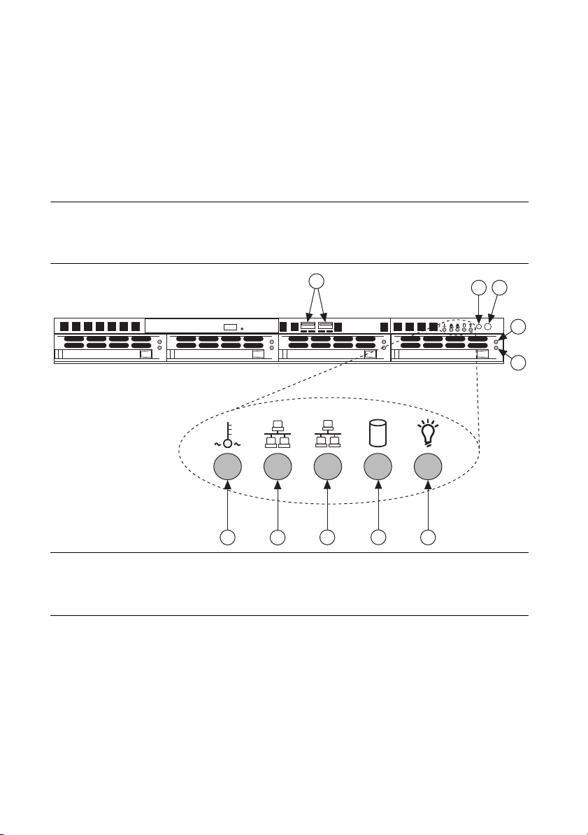
Figure 1-1 shows the key features of the NI RMC-8354 front panel. For detailed information
about the NI RMC-8354 rear panel, refer to Chapter 3, I/O Information.
Figure 1-1. Front View of the NI RMC-8354
1
7
6
1USB Ports
2 Reset Switch
3 Power Switch
4 Hard Drive Activity Indicator
5 Hard Drive Error Indicator
10
9
8
6 Power Indicator
7 HDD Indicator
8 LAN1 Status Indicator
9 LAN2 Status Indicator
10 System Temp and Fan Warning Indicator
The front panel includes the following LEDs:
• Power indicator—glows when the NI RMC-8354 is powered on.
• LAN status indicators—flash when there is activity on LAN1 or LAN2.
• Overheat/FanFail LED
– Off—Normal
– On—Overheat
– Flashing—Fan failure warning
2
3
4
RESET
5
1-4 | ni.com
Page 14

NI RMC-8354 User Manual
Optional Equipment
Memory Upgrades
You can upgrade the NI RMC-8354 memory to a maximum of 16 GB.
Note A 32-bit operating system such as Windows XP Pro addresses a maximum
of 4 GB.
The NI RMC-8354 supports dual-channel DDR-3 SDRAM unbuffered memory in four 240-pin
DIMM sockets. The NI RMC-8354 is compatible with ECC memory.
Note Supported DIMM sizes are 1 GB, 2 GB, and 4 GB.
Note National Instruments has tested and verified that the DDR-3 DIMMs we sell
work with the NI RMC-8354. We recommend you purchase your DDR-3 DIMM
modules from National Instruments. Other off-the-shelf DDR-3 DIMM modules
are not guaranteed to work properly.
USB Floppy Disk Drive
A USB floppy drive is available from National Instruments, part number 778492-02.
National Instruments Software
National Instruments hardware and software work together to help you make the most of your
PXI Express system. The LabVIEW, Measurement Studio, and LabWindows™/CVI™
application development environments combine with leading hardware drivers such as
NI-DAQmx to provide exceptional control of NI hardware. Instrument drivers are available at
ni.com/idnet to simplify communication with instruments over a variety of buses.
LabVIEW is a powerful and easy-to-use graphical programming environment you can use to
acquire data from thousands of different instruments including USB, IEEE 488.2, VXI, serial,
PLCs, and plug-in boards. LabVIEW helps you convert acquired data into meaningful results
using powerful data analysis routines. Add-on tools provide additional specialized functionality.
For more information, visit
If you prefer to use Microsoft’s Visual Basic, Visual C++, and Visual Studio .NET for the core
of your application, Measurement Studio adds tools for measurement and automation to each
language. For more information, visit
LabWindows/CVI is an interactive ANSI C programming environment designed for building
virtual instrument applications. LabWindows/CVI includes a drag-and-drop editor for building
user interfaces, a complete ANSI C environment for building your test program logic, and a
collection of automated code generation tools, as well as utilities for building automated test
ni.com/labview and ni.com/toolkits.
ni.com/mstudio.
© National Instruments | 1-5
Page 15

Chapter 1 Getting Started
systems, monitoring applications, or laboratory experiments. For more information, visit
ni.com/lwcvi.
NI-DAQmx provides an extensive library of functions you can call from your application
development environment or interactive environment, such as NI Signal Express. These
functions provide an intuitive API for National Instruments multifunction DAQ products.
Features include analog input (A/D conversion), buffered data acquisition (high-speed A/D
conversion), analog output (D/A conversion), waveform generation, digital I/O, counter/timer
operations, SCXI signal conditioning, RTSI or PXI synchronization, self-calibration, messaging,
and acquiring data to extended memory. For more information, visit
ni.com/daq.
National Instruments modular instruments use specialized drivers suited to each product’s
specialization. Express VIs provide customized, interactive programming of instruments in a
single interface, and soft front panels provide an interface for testing the functionality of each
instrument with no programming required. NI switches, DMMs, high-speed DIO, high-speed
digitizers, and sources each have customized drivers for high-end modular instrumentation
systems. RF applications leverage two drivers, NI-RFSG and NI-RFSA, and dynamic signal
acquisition is available through NI-DAQmx. For more information, visit
modularinstruments
.
ni.com/
You can expand the timing and triggering functionality of your PXI system with PXI timing and
synchronization products. These products provide precision clock sources, custom routing of
triggers for multichassis synchronization, clock sharing, and more, and are programmed with
NI-Sync. For more information, visit
ni.com/pxi.
NI-VISA is the National Instruments implementation of the VISA specification. VISA is a
uniform API for communicating and controlling USB, Serial, GPIB, PXI, VXI, and various
other types of instruments. This API aids in the creation of portable applications and instrument
drivers. For information about writing your own PXI instrument driver with NI-VISA, refer to
the NI-VISA Help and the
readme.txt file in the NI-VISA directory. For more information,
visit ni.com/visa.
1-6 | ni.com
Page 16

2
Installation and BIOS Setup
This chapter describes how to install, configure, and use the NI RMC-8354.
Before connecting the NI RMC-8354 to a power source, read this chapter and the Read Me First:
Safety and Electromagnetic Compatibility document included with your NI RMC-8354.
Safety Information
Caution Before undertaking any troubleshooting, maintenance, or exploratory
procedure, carefully read the following caution notices.
Caution Overloading the circuits may damage supply wiring. Do not exceed the
ratings on the equipment nameplate when connecting equipment to the supply circuit.
Caution Risk of explosion if battery is replaced by an incorrect type. dispose of
used batteries according to instructions.
This equipment contains voltage hazardous to human life and safety, and is capable of inflicting
personal injury.
• Chassis Grounding—The NI RMC-8354 requires a connection from the premise wire
safety ground to the NI RMC-8354 chassis ground. The earth safety ground must be
connected during use of this equipment to minimize shock hazards. Refer to the Connecting
Safety Ground section for instructions on connecting safety ground.
• Live Circuits—Operating personnel and service personnel must not remove protective
covers when operating or servicing the NI RMC-8354. Adjustments and service to internal
components must be undertaken by qualified service technicians. During service of
this product, the mains connector to the premise wiring must be disconnected. Dangerous
voltages may be present under certain conditions; use extreme caution.
• Explosive Atmosphere—Do not operate the chassis in conditions where flammable gases are
present. Under such conditions, this equipment is unsafe and may ignite the gases or gas fumes.
• Parts Replacement—Service this equipment only with parts that are exact replacements,
both electrically and mechanically. Contact National Instruments for replacement part
information. Installation of parts with those that are not direct replacements may cause
harm to personnel operating the chassis. Furthermore, damage or fire may occur if
replacement parts are unsuitable.
• Modification—Do not modify any part of the NI RMC-8354 from its original condition.
Unsuitable modifications may result in safety hazards.
© National Instruments | 2-1
Page 17
Chapter 2 Installation and BIOS Setup
Chassis Cooling Considerations
The NI RMC-8354 is designed to operate in an instrument rack. Follow the appropriate
installation instructions.
Caution If installed in a closed or multiunit rack assembly, the rack environment
operating ambient temperature may be greater than room ambient temperature.
Therefore, install the equipment in an environment compatible with the maximum
ambient operating temperature (Tma) specified in Appendix A, Specifications.
Providing Adequate Clearance
Apertures in the front, top, rear, and along both sides of the chassis facilitate power supply and
motherboard cooling. Air enters through the front and top inlets of the chassis and exits through
the fans on the rear of the chassis. Place the NI RMC-8354 in an instrument rack so that the fans
(air outlets) and the air inlet apertures along the top and front of the chassis have adequate
ventilation. Keep other equipment a minimum of 76.2 mm (3 in.) away from the air outlets on
the rear of the chassis.
Installation
Follow these steps to connect devices to the NI RMC-8354:
Caution Because of the risk of high energy (>240VA), the unit must be installed
only in a Restricted Access Location.
1. Connect a keyboard and mouse to the appropriate connectors on the NI RMC-8354 rear
panel.
2. Connect the VGA monitor video cable to the VGA connector on the rear panel.
3. (Optional) To boot into LabVIEW RT, connect the network cable to LAN jack 1 on the rear
panel. (Refer to Figure 3-1, NI RMC-8354 Rear Panel Layout, for the location of LAN jack 1.)
4. Connect the USB, serial, and parallel devices as necessary to the NI RMC-8354 front and
rear panel ports.
Caution To minimize shock hazard, make sure the electrical power outlet you use
to power the NI RMC-8354 has an appropriate earth safety ground. Refer to the
Connecting Safety Ground section for more information.
5. Connect the AC power cable to the AC inlet on the rear panel and to an AC power outlet.
For more information, refer to the Connecting to Power Source section.
6. Power on the NI RMC-8354.
7. Verify that the NI RMC-8354 boots. If it does not boot, refer to the What if the NI
RMC-8354 does not boot? section of Chapter 5, Troubleshooting.
2-2 | ni.com
Page 18
NI RMC-8354 User Manual
Connecting Safety Ground
The NI RMC-8354 is designed with a three-position NEMA 5-15 style plug for the U.S. that
connects the ground line to the chassis ground. To minimize shock hazard, make sure the
electrical power outlet you use to power the chassis has an appropriate earth safety ground.
Connecting to Power Source
Attach input power through the rear AC inlet using the appropriate AC power cable supplied.
Caution Overloading the circuits may damage supply wiring. Do not exceed the
ratings on the equipment nameplate when connecting equipment to the supply circuit.
Caution To completely remove power, you must disconnect the AC power cable.
The power switch allows you to power on the chassis or place it in standby mode. Push the power
switch to the On position (if not already on). Observe that all fans become operational and the
power indicator is lit.
BIOS Setup
This section describes all main BIOS setup options.
To enter the BIOS menu, press <Del>. Use the up and down arrow keys to move among the
different settings in each menu. Use the left and right arrow keys to change the options for each
setting.
Press <Esc> to exit the CMOS setup menu. The next section describes in detail how to navigate
through the menus.
To access submenus, highlight a menu item and press <Enter>.
Note To reset the BIOS to the default settings, load the optimal defaults by pressing
<F9> in the BIOS Setup Utility. Optimal default settings default to the following:
• Disable the floppy controller
• Disable serial port 2 (COM2)
• Enable RAID (Intel)
• Set the fan speed control modes to balanced
• Enable Intel C-STATE tech
• Disable Remote Access configuration
© National Instruments | 2-3
Page 19

Chapter 2 Installation and BIOS Setup
Main BIOS Setup Menu
The main BIOS setup menu includes the following items:
• Device name: Supermicro X8SIE/X8SIE-F/X8SIE-LN4/X8SI6-F
•Version
• Build date
• Processor
The AMI BIOS automatically displays the following processor status items:
– Type of processor
–Speed
– Physical count
– Logical count
• System memory
The system memory displays the following memory sizes available in the system:
– Populated size
– Available size
Advanced Setup Configurations
Use the arrow keys to select Boot Setup and press <Enter> to access the submenu items.
Boot Feature
This menu includes the following options.
Quick Boot
If enabled, this option skips certain tests during POST to reduce the time needed for system boot.
The options are Enabled and Disabled.
Quiet Boot
Use this option to modify the bootup screen options between POST messages or the OEM logo.
Select Disabled to display the POST messages. Select Enabled to display the OEM logo instead
of the normal POST messages. The options are Enabled and Disabled.
AddOn ROM Display Mode
This option sets the option ROM display mode. The options are Force BIOS and Keep Current.
Bootup Num-Lock
This option selects the numlock key power-on state. The options are Off and On.
PS/2 Mouse Support
This option enables support for the PS/2 mouse. The options are Disabled, Enabled, and Auto.
2-4 | ni.com
Page 20

NI RMC-8354 User Manual
Wait For “F1” If Error
This option forces the system to wait until <F1> is pressed if an error occurs. The options are
Disabled and Enabled.
Hit “Del” Message Display
This option displays Press DEL to run Setup during POST. The options are Enabled and
Disabled.
Watch Dog Function
If enabled, the watch dog timer allows the system to reboot when it is inactive for more than
5 minutes. The options are Enabled and Disabled.
Power Button Mode
Use this option to decide whether the power button turns off the system instantly or waits
4 seconds when pressed. The options are Instant Off and 4 Seconds Override.
Restore on AC Power Loss
Use this option to set the power state after a power outage. Select Power-Off for the system
power to remain off after a power loss. Select Power-On for the system power to be turned on
after a power loss. Select Last State to allow the system to resume its last state before a power
loss. The options are Power-On, Power-Off, and Last State.
Interrupt 19 Capture
Interrupt 19 is the software interrupt that handles the boot disk function. When you set this item
to Enabled, the host adaptors ROM BIOS “captures” interrupt 19 at boot and allows the drives
attached to these host adaptors to function as bootable disks. If you set this item to Disabled, the
host adaptors ROM BIOS does not capture interrupt 19, and the drives attached to these adaptors
do not function as bootable devices. The options are Enabled and Disabled.
Processor and Clock Options
Caution Be careful when changing the advanced settings. An incorrect value, very
high DRAM frequency, or incorrect DRAM timing may cause the system to become
unstable. If this occurs, revert to the default setting.
CPU Ratio
Use this option to use the CPU clock multiplier to multiply CPU speed to enhance performance.
Select Manual to set the multiplier setting manually. Select Auto for the BIOS to select the CPU
multiplier setting for your system automatically. The options are Default and Manual.
Clock Spread Spectrum
Select Enable to use the clock spectrum feature, which allows the BIOS to monitor and reduce
the electromagnetic interference level that the components cause. Select Disabled to enhance
system stability. The options are Disabled and Enabled.
© National Instruments | 2-5
Page 21

Chapter 2 Installation and BIOS Setup
Hardware Prefetcher (Available Subject to CPU Support)
If set to Enabled, the hardware prefetcher prefetches streams of data and instructions from the
main memory to the L2 cache in the forward or backward manner to improve CPU performance.
The options are Disabled and Enabled.
Adjacent Cache Line Prefetch (Available Subject to CPU Support)
The CPU fetches the cache line for 64 bytes if you set this option to Disabled. If you set this
option to Enabled, the CPU fetches both cache lines for 128 bytes as comprised.
MPS and ACPI MADT Ordering
Use this option to choose the ordering method for the Multiple ACPI Description Table
(MADT). Select Modern Ordering for Windows XP or later. Select Legacy Ordering for
Microsoft Windows 2000 or earlier. The options are Modern Ordering and Legacy Ordering.
Intel Virtualization Technology (Available Subject to CPU Support)
Select Enabled to use the virtualization technology feature to allow one platform to run multiple
OSs and applications in independent partitions, creating multiple “virtual” systems in one
physical computer. The options are Enabled and Disabled.
Note If you change to this setting, you must power off and restart the system for the
change to take effect. Refer to
virtualization
for detailed information.
www.intel.com/technology/
Execute Disable Bit Capability (Available Subject to OS and CPU Support)
Set to Enabled to enable the Execute Disable Bit, which allows the processor to designate areas
in the system memory where application code can execute and where it cannot, thus preventing
a worm or virus from flooding illegal codes to overwhelm the processor or damage the system
during an attack. The default is Enabled. (Refer to the Intel and Microsoft Web sites for more
information.)
Simultaneous Multithreading (Available Subject to CPU Support)
Set to Enabled to use hyperthreading technology for increased CPU performance. The options
are Disabled and Enabled.
Active Processor Cores
Set to Enabled to use a processor’s second core and beyond. (Refer to the Intel Web site for
more information.) The options are All, 1, 2, 3, and 4.
Intel EIST Technology
With Enhanced Intel SpeedStep Technology (EIST), the system can adjust processor voltage and
core frequency automatically to reduce power consumption and heat dissipation. Refer to the
Intel Web site for detailed information. The options are Disabled and Enabled.
2-6 | ni.com
Page 22

NI RMC-8354 User Manual
Intel Turbo Boost Technology (Available If Intel EIST is Enabled)
With this option, processor cores can run faster than the marked frequency in specific conditions.
The options are Disabled and Enabled.
C1E Support
Select Enabled to use the Enhanced Halt State feature. C1E significantly reduces CPU power
consumption by reducing the CPU clock cycle and voltage during a Halt State. The options are
Disabled and Enabled.
Intel C-State Tech
If enabled, the system automatically sets the C-state to either C2, C3, or C4 state. The options
are Default and Enabled.
C-State Package Limit Setting
If set to Auto, the AMI BIOS automatically sets the C-state package register limit. The options
are Auto, C1, C3, C6, and C7.
C1 Auto Demotion
When enabled, the CPU conditionally demotes C3, C6, or C7 requests to C1 based on un-core
auto-demote information. The options are Disabled and Enabled.
C3 Auto Demotion
When enabled, the CPU conditionally demotes C6 or C7 requests to C3 based on un-core
auto-demote information. The options are Disabled and Enabled.
Advanced Chipset Control
The Advanced Chipset Control submenu includes the following items.
Memory Remap Feature
Enable this option to remap overlapped PCI memory above the total physical memory. The
settings are Enabled and Disabled.
Intel VT-d
Select Enabled to enable Intel virtualization technology support for direct I/O VT-d by
reporting the I/O device assignments to VMM through the DMAR ACPI tables. This feature
offers fully protected I/O resource sharing across Intel platforms for greater reliability, security,
and availability in networking and data sharing. The settings are Enabled and Disabled.
Active State Power Management
Select Enabled to start Active State Power Management for signal transactions between L0 and
L1 links on the PCI Express bus. This maximizes power saving and transaction speed. The
options are Enabled and Disabled.
© National Instruments | 2-7
Page 23

Chapter 2 Installation and BIOS Setup
Route Port 80h Cycles to
Use this option to send debug information to a specific bus. The options are Disabled, PCI,
and LPC.
USB Functions
Use this option to decide the number of onboard USB ports to enable. The options are Disabled
and Enabled.
Legacy USB Support (Available if USB Functions is Enabled)
Select Enabled to use legacy USB devices. If you set this item to Auto, legacy USB support is
enabled automatically if a legacy USB device is installed on the motherboard, and vise versa.
The settings are Disabled, Enabled, and Auto.
SATA/Floppy Configuration
When you select this submenu, the AMI BIOS automatically detects IDE device presence and
displays the following items.
Floppy A
Use this option to select the type of floppy drive connected to the system. The options are
Disabled, 360 KB 5 1/4”, 1.2 MB 5 1/4”, 720 KB 3 1/2”, 1.44 MB 3 1/2”, and 2.88 MB 3 1/2”.
SATA#1 Configuration
Selecting Compatible sets SATA#1 to legacy compatibility mode, while selecting Enhanced
sets SATA#1 to native SATA mode. The options are Disabled, Compatible, and Enhanced.
Configure SATA as
Use this item to select the SATA#1 drive type. The options are IDE, RAID, and AHCI.
PCH RAID CodeBase
Select Intel to enable the Intel SATA HostRAID Utility. Select Adaptec to use the Adaptec
HostRAID Utility. The options are Intel and Adaptec.
SATA#2 Configuration (Available If IDE Is Enabled Under Configure
SATA#1 as)
Select Enhanced to set SATA#2 to native SATA mode. The options are Disabled and
Enhanced.
IDE Detect Timeout (sec)
Use this option to set the timeout value for the BIOS to detect the ATA and ATAPI devices
installed in the system. The options are 0 (seconds), 5, 10, 15, 20, 25, 30, and 35.
2-8 | ni.com
Page 24

NI RMC-8354 User Manual
SATA 0 ~ 5r
Use these settings to set the parameters of the disc storage devices attached to the SATA ports.
Press <Enter> to activate the submenu screen for detailed item options. Set the correct
configurations accordingly. The submenu items are listed below.
Type
Select the device type connected to the system. The options are Not Installed, Auto, CD/DVD,
and ARMD.
LBA/Large Mode
Logical Block Addressing (LBA) is a method of addressing data on a disk drive. In the LBA
mode, the maximum drive capacity is 137 GB. For drive capacities over 137 GB, your system
must be equipped with a 48-bit LBA mode addressing. If not, install an ATA/133 IDE controller
card that supports 48-bit LBA mode. The options are Disabled and Auto.
Block (Multi-Sector Transfer)
Block Mode boosts the IDE drive performance by increasing the amount of data transferred. You
can transfer only 512 bytes of data per interrupt if you do not use Block Mode. Block Mode
allows transfers of up to 64 KB per interrupt. If you select Disabled, data can transfer to and
from the device one sector at a time. If you select Auto, data can transfer to and from the device
multiple sectors at a time if the device supports this transfer method. The options are Auto and
Disabled.
PIO Mode
The IDE Programmable I/O (PIO) mode programs timing cycles between the IDE drive and
programmable IDE controller. As the PIO mode increases, the cycle time decreases. The options
are Auto, 0, 1, 2, 3, and 4.
If you select Auto, the AMI BIOS detects the PIO mode automatically. Use this value if you
cannot determine IDE disk drive support.
If you select 0, the AMI BIOS uses PIO mode 0. The data transfer rate is 3.3 Mbytes/s.
If you select 1, the AMI BIOS uses PIO mode 1. The data transfer rate is 5.2 Mbytes/s.
If you select 2, the AMI BIOS uses PIO mode 2. The data transfer rate is 8.3 Mbytes/s.
If you select 3, the AMI BIOS uses PIO mode 3. The data transfer rate is 11.1 Mbytes/s.
If you select 4, the AMI BIOS uses PIO mode 4. The data transfer bandwidth is 32 bits. Select
Enabled to enable 32-bit data transfer.
DMA Mode
If you select Auto, the BIOS detects IDE DMA mode automatically when you cannot determine
IDE disk drive support.
If you select SWDMA0, the BIOS uses single word DMA mode 0. The data transfer rate is
2.1 Mbytes/s.
© National Instruments | 2-9
Page 25

Chapter 2 Installation and BIOS Setup
If you select SWDMA1, the BIOS uses single word DMA mode 1. The data transfer rate is
4.2 Mbytes/s.
If you select SWDMA2, the BIOS uses single word DMA mode 2. The data transfer rate is
8.3 Mbytes/s.
If you select MWDMA0, the BIOS uses multiword DMA mode 0. The data transfer rate is
4.2 Mbytes/s.
If you select MWDMA1, the BIOS uses multiword DMA mode 1. The data transfer rate is
13.3 Mbytes/s.
If you select MWDMA2, the BIOS uses multiword DMA mode 2. The data transfer rate is
16.6 Mbytes/s.
If you select UDMA0, the BIOS uses ultra DMA mode 0. The data transfer rate is 16.6 Mbytes/s.
It has the same transfer rate as PIO mode 4 and multiword DMA mode 2.
If you select UDMA1, the BIOS uses ultra DMA mode 1. The data transfer rate is 25 Mbytes/s.
If you select UDMA2, the BIOS uses ultra DMA mode 2. The data transfer rate is 33.3 Mbytes/s.
If you select UDMA3, the BIOS uses ultra DMA mode 3. The data transfer rate is 66.6 Mbytes/s.
If you select UDMA4, the BIOS uses ultra DMA mode 4. The data transfer rate is 100 Mbytes/s.
The options are Auto, SWDMAn, MWDMAn, and UDMAn.
SMART for Hard Disk Drives
Self-Monitoring Analysis and Reporting Technology (SMART) helps predict impending drive
failures. If you select Auto, the AMI BIOS detects hard disk drive support automatically. Select
Disabled to prevent the AMI BIOS from using the SMART. Select Enabled to allow the AMI
BIOS to use the SMART. to support the hard drive disk. The options are Disabled, Enabled,
and Auto.
32-Bit Data Transfer
Select Enable to enable the function of 32-bit IDE data transfer. The options are Enabled and
Disabled.
PCI/PnP Configuration
Use this menu to set the PCI/PnP configurations for the following items.
Clear NVRAM
This option clears the NVRAM during system boot. The options are No and Yes.
2-10 | ni.com
Page 26

NI RMC-8354 User Manual
Plug & Play OS
If you select Yes, the OS configures Plug & Play devices. (This is not required for system boot
if your system has an OS that supports Plug & Play.) If you select No, the AMI BIOS configures
all devices in the system.
PCI Latency Timer
This option sets the latency timer of each PCI device installed on a PCI bus. Select 64 to set the
PCI latency to 64 PCI clock cycles. The options are 32, 64, 96, 128, 160, 192, 224, and 248.
PCI IDE Bus Master
When enabled, the BIOS uses PCI bus mastering for reading/writing to IDE drives. The options
are Disabled and Default.
PCIE I/O Performance
This feature selects the setting for the IOH PCI Express maximum payload size. The options are
128B and 256B.
ROM Scan Ordering
This option determines what kind of option ROM activates over another. The options are
Onboard First and Add-On First.
PCI Slot 1, PCIe Slot 2 & 6 OPROM
Use this option to enable or disable PCI slot option ROMs. The options are Disabled and
Enabled.
Load Onboard LAN1 Option ROM
This option enables or disables the onboard LAN option ROMs. The options are Disabled and
Enabled.
Load Onboard LAN2 Option ROM
This option enables or disables the onboard LAN option ROMs. The options are Disabled and
Enabled.
Boot Graphics Adapter Priority
Use this option to select the graphics controller used as the primary boot device. The options are
Other, Onboard VGA, and Slot 6. Select Slot 6 if a graphics controller is installed in the
CPU-controlled slot 6 slot.
© National Instruments | 2-11
Page 27

Chapter 2 Installation and BIOS Setup
Super IO Device Configuration
This menu includes the following options.
Serial Port1 Address/Serial Port2 Address
This option specifies the Serial Port 1 and Serial Port 2 base I/O port address and Interrupt
Request address. Select Disabled to prevent the serial port from accessing any system resources.
When you set this option to Disabled, the serial port physically becomes unavailable. If you
select 3F8/IRQ4, the serial port uses 3F8 as its I/O port address and IRQ 4 for the interrupt
address. The options for Serial Port1 are Disabled, 3F8/IRQ4, and 2E8/IRQ3. The options for
Serial Port2 are Disabled, 2F8/IRQ3, and 2E8/IRQ3.
Onboard Floppy Controller
Select Enabled to enable the onboard floppy controller. The options are Enabled and Disabled.
Remote Access Configuration
This menu includes the following items.
Remote Access
Use this option to enable the Remote Access feature. The options are Disabled and Enabled.
If you set Remote Access to Enabled, the following items display.
Serial Port Number
Use this option to select the serial port for console redirection. The options are COM 1,
COM 2, and COM 3.
Note Serial Over LAN (SOL) is enabled on COM 3 on the X8SIE-F and X8SI6-F.
Serial Port Mode
Use this option to set the serial port mode for Console Redirection. The options are 115200 8, n,
1; 57600 8, n, 1; 38400 8, n, 1; 19200 8, n, 1; and 9600 8, n, 1.
Flow Control
Use this option to set the flow control for Console Redirection. The options are None,
Hardware, and Software.
Redirection After BIOS POST
Select Disabled to turn off Console Redirection after Power-On Self-Test (POST). Select
Always to keep Console Redirection active all the time after POST. (Some OSs may not support
this setting.) Select Boot Loader to keep Console Redirection active during POST and Boot
Loader. The options are Disabled, Boot Loader, and Always.
Terminal Type
Use this option to select the target terminal type for Console Redirection. The options are ANSI,
VT100, and VT-UTF8.
2-12 | ni.com
Page 28

NI RMC-8354 User Manual
VT-UTF8 Combo Key Support
This option is a terminal keyboard definition for sending commands from a remote console.
Available options are Enabled and Disabled.
Sredir Memory Display Delay
This feature defines the length of time in seconds to display memory information. The options
are No Delay, Delay 1 Sec, Delay 2 Sec, and Delay 4 Sec.
Hardware Health Configuration
Use this menu to monitor system hardware health and review the status of each item when
displayed.
CPU Overheat Alarm
Use this option to select the CPU Overheat Alarm setting, which determines when the CPU
overheat alarm is activated to warn of possible CPU overheat.
Caution Any temperature that exceeds the CPU threshold temperature that the
CPU manufacturer predefines may result in CPU overheat or system instability.
When the CPU temperature reaches this predefined threshold, the CPU and system
cooling fans run at full speed.
The options are:
• Early Alarm—Select this setting to trigger the CPU overheat alarm (including the LED
and buzzer) as soon as the CPU temperature reaches the CPU overheat threshold that the
CPU manufacturer predefines.
• Default Alarm—Select this setting to trigger the CPU overheat alarm (including the LED
and buzzer) when the CPU temperature reaches about 5 °C above the threshold temperature
that the CPU manufacturer predefines, to give the CPU and system fans additional time
needed for CPU and system cooling. In both the alarms above, take immediate action as
described below.
System Temperature
This option displays the absolute system temperature (for example, 34 °C).
CPU Temperature
The CPU Temperature option displays the CPU temperature status as the BIOS detects it:
• Low—This level is considered the normal operating state. The CPU temperature is well
below the CPU temperature tolerance. The motherboard fans and CPU run normally as
configured in the BIOS (Fan Speed Control).
User Intervention: No action required.
• Medium—The processor is running warmer. This is a precautionary level and generally
means there may be factors contributing to this condition, but the CPU still is within its
normal operating state and below the CPU temperature tolerance. The motherboard fans
© National Instruments | 2-13
Page 29

Chapter 2 Installation and BIOS Setup
and CPU run normally as configured in the BIOS. The fans may adjust to a faster speed
depending on the Fan Speed Control settings.
User Intervention: No action is required. However, consider checking the CPU fans and
chassis ventilation for blockage.
• High—The processor is running hot. This is a caution level, because the CPU temperature
tolerance has been reached (or has been exceeded) and may activate an overheat alarm:
– Default Alarm—The Overheat LED and system buzzer activate if the High condition
continues for some time after it is reached. The CPU fan runs at full speed to bring
down the CPU temperature. If the CPU temperature still increases even with the CPU
fan running at full speed, the system buzzer activates and the Overheat LED turns on.
– Early Alarm—The Overheat LED and system buzzer are activated exactly when the
High level is reached. The CPU fan runs at full speed to bring down the CPU
temperature.
Caution In both the alarms above, take immediate action as described below.
Refer to the CPU Overheat Alarm section to modify the above alarm settings.
User Intervention: If the system buzzer and Overheat LED has activated, take action
immediately by checking the system fans, chassis ventilation, and room temperature to
correct any problems.
Note The system may shut down if it continues for a long period to prevent damage
to the CPU.
Note In its newer processors, Intel has upgraded the CPU thermal technology that
reports absolute temperatures (Celsius/Fahrenheit) to a more advanced feature. The
basic concept is that each CPU has unique embedded temperature information that
the motherboard can read. This temperature threshold or temperature tolerance is
assigned at the factory and is the baseline by which the motherboard takes action
during different CPU temperature conditions (for example, increasing CPU fan
speed, triggering the overheat alarm, etc.). Because CPUs can have different
temperature tolerances, the installed CPU now can send its temperature tolerance to
the motherboard, resulting in better CPU thermal management.
The information provided above is for your reference only. For more information about thermal
management, refer to the Intel Web site at
www.Intel.com.
Fan Speed Control Modes
Use this option to decide how the system controls the speeds of the onboard fans. The CPU
temperature and fan speed are correlative. When the CPU on-die temperature increases, the fan
speed also increases for effective system cooling.
2-14 | ni.com
Page 30

NI RMC-8354 User Manual
Select Full Speed to allow the onboard fans to run at full speed (100 percent Pulse Width
Modulation Duty Cycle) for maximum cooling. The Full Speed setting is recommended for
special system configuration or debugging.
Select Performance for the onboard fans to run at 70 percent of the Initial PWM Cycle for better
system cooling. The Performance setting is recommended for high-power-consuming and
high-density systems.
Select Balanced for the onboard fans to run at 50 percent of the Initial PWM Cycle to balance
the needs between system cooling and power saving. The Balanced setting is recommended for
regular systems with normal hardware configurations.
Select Energy Saving for the onboard fans to run at 30 percent of the Initial PWM Cycle for
best power efficiency and maximum quietness.
The options are Full Speed (@100% of PWM Cycle), Performance (@70% of PWM Cycle),
Balanced (@50% of PWM Cycle), and Energy Saving (@30% of PWM Cycle).
Fan1 ~ Fan 6 Reading
This option displays the fan speed readings from fan interfaces Fan1 through Fan5. The options
are Vcore, AVCC, 3.3Vcc, 12V, V_DIMM, 5V, –12V, 3.3Vsb, and Vbat.
ACPI Configuration
Use this menu to configure Advanced Configuration and Power Interface (ACPI) power
management settings for your system.
High-Performance Event Timer
Select Enabled to activate the High-Performance Event Timer (HPET) that produces periodic
interrupts at a much higher frequency than a real-time clock (RTC) does in synchronizing
multimedia streams. This provides smooth playback and reduces the dependency on other
timestamp calculation devices such as an x86 RDTSC Instruction embedded in the CPU. The
High-Performance Event Timer replaces the 8254 Programmable Interval Timer. The options
are Enabled and Disabled.
ACPI Aware O/S
This option enables ACPI support (if the OS supports it) to control ACPI through the OS.
Otherwise, disable this feature. The options are Yes (enabled) and No (disabled).
ACPI APIC Support
Select Enabled to include the ACPI APIC Table Pointer in the Root System Description Table
(RSDT) pointer list. The options are Enabled and Disabled.
APIC ACPI SCI IRQ
When you set this item to Enabled, the system supports APIC ACPI SCI IRQ. The options are
Enabled and Disabled.
© National Instruments | 2-15
Page 31

Chapter 2 Installation and BIOS Setup
Headless Mode
Use this feature to enable the system to function without a keyboard, monitor, or mouse attached.
The options are Enabled and Disabled.
ACPI Version Features
The options are ACPI v1.0, ACPI v2.0, and ACPI v3.0. Refer to the ACPI Web site at
www.acpi.info/ for further explanation.
Event Log Configuration
This menu includes the following items.
View Event Log
Use this option to view the System Event Log.
Mark All Events as Read
This option marks all events as read. The options are OK and Cancel.
Clear Event Log
This option clears the event log memory of all messages. The options are OK and Cancel.
PCIE Error Log
Use this option to enable logging of errors encountered in the system PCI Express bus. The
options are Yes and No.
Security Settings
The AMI BIOS provides a supervisor and user password. If you use both passwords, you must
set the supervisor password first.
Supervisor Password
This option indicates whether you have set a supervisor password for the system. Clear means
you have not set a supervisor password, and Set means you have set one.
User Password
This item indicates whether you have set a user password for the system. Clear means you have
not set a user password, and Set means you have set one.
Change Supervisor Password
Select this feature and press <Enter> to access the submenu, then type in a new supervisor
password.
2-16 | ni.com
Page 32

NI RMC-8354 User Manual
User Access Level
This option is available when you set a supervisor password. Available options are:
• Full Access—You have full read and write access to the setup utility.
• View Only—You can access to the setup utility, but cannot change the fields.
• Limited—You can change only limited fields such as Date and Time.
• No Access—You do not have access to the setup utility.
Change User Password
Select this feature and press <Enter> to access the submenu, then type in a new user password.
Clear User Password
This option is available only if you set a user password.
Password Check
Available options are Setup and Always.
Boot Sector Virus Protection
When enabled, the AMI BOIS displays a warning when any program (or virus) issues a disk
format command or attempts to write to the hard disk drive boot sector. The options are Enabled
and Disabled.
Boot Settings
Use the following options in this menu to configure boot settings.
Boot Device Priority
Use this option to specify the boot device priority sequence. The settings are 1st boot device,
2nd boot device, 3rd boot device, 4th boot device, 5th boot device, and Disabled.
• 1st boot device: First floppy drive
• 2nd boot device: [USB: XXXXXXXXX]
• 3rd boot device: [SATA: XXXXXXXXX]
• 4th boot device: [Network: XXXXXXXXX]
• 5th boot device: [Network: XXXXXXXXX]
Hard Disk Drives
Use this option to specify the hard drive priority sequence.
• 1st drive: [SATA: XXXXXXXXXX]
• 2nd drive: [SATA: XXXXXXXXXX]
© National Instruments | 2-17
Page 33

Chapter 2 Installation and BIOS Setup
Removable Drives
Use this option to specify the removable drive boot sequence. The settings are 1st boot device,
2nd boot device, and Disabled.
•1st drive
• 2nd drive: [USB: XXXXXXXXX]
Retry Boot Devices
Select this option to retry booting from the configured boot devices if the systems fail to boot
initially. The options are Disabled and Enabled.
Exit Options
Select the Exit tab from the AMI BIOS Setup Utility screen to enter the Exit BIOS Setup screen.
Save Changes and Exit
When you have completed the system configuration changes, select this option to leave the
BIOS Setup Utility and reboot the computer so the new system configuration parameters can
take effect. Select Save Changes and Exit from the Exit menu and press <Enter>.
Discard Changes and Exit
Select this option to quit the BIOS Setup Utility without making any permanent changes to the
system configuration and reboot the computer. Select Discard Changes and Exit from the Exit
menu and press <Enter>.
Discard Changes
Select this option and press <Enter> to discard all changes and return to the AMI BIOS Setup
Utility.
Load Optimal Defaults
To set this option, select Load Optimal Defaults from the Exit menu and press <Enter>. Then
select OK to allow the AMI BIOS to load optimal defaults to the BIOS settings automatically.
The optimal settings are for maximum system performance, but may not work best for all
computer applications.
Load Fail-Safe Defaults
To set this option, select Load Fail-Safe Defaults from the Exit menu and press <Enter>. The
fail-safe settings are for maximum system stability, but not for maximum performance.
POST Error Beep Codes
This section lists Power On Self Test (POST) error beep codes for the AMI BIOS. POST error
beep codes are in two categories: recoverable and terminal. This section lists beep codes for
recoverable POST errors.
2-18 | ni.com
Page 34

NI RMC-8354 User Manual
Recoverable POST Error Beep Codes
When a recoverable error occurs during POST, the BIOS displays a POST code that describes
the problem. The BIOS also may issue one of the following beep codes:
• One long and eight short beeps: Video configuration error.
• One repetitive long beep: No memory detected.
• One continuous beep with the front panel Overheat LED on: System overheat.
Rack Mounting
Note The rack mount kit provided with the NI RMC-8354 is intended to work with
racks that are 26 to 33 in. deep. For information about installing the NI RMC-8354
into a rack that is less than 26 in. deep, refer to KnowledgeBase 4GCEKKMT at
ni.com/support.
The rack mounting hardware includes:
• One pair of inner slides to be installed on the chassis.
• One pair of outer slides to be installed in the rack.
• Three pairs of short brackets for the outer slides.
• Bag of assorted fasteners.
• One pair of long brackets for the rear of the outer slides.
Caution When mounting the equipment in the rack, do not create a hazardous
condition due to uneven mechanical loading.
Note One pair of short brackets includes screw threads, and the other two pairs
have slots. If the short brackets are required for your specific rack mounting
configuration, use the pair(s) that fits into your rack best.
Note Rack mounting hardware provided in the accessory kit, but not specifically
described in the following instructions, is for other possible rack mounting
configurations not mentioned in this manual. Consult any relevant literature provided
with the intended rack for specific mounting information before attempting to install
the NI RMC-8354.
© National Instruments | 2-19
Page 35

Chapter 2 Installation and BIOS Setup
1
3
2
Installing the Inner Slides
Follow these steps to install the inner slides to the NI RMC-8354:
1. Locate the right inner slide (the slide used on the right side of the chassis when facing the
chassis front panel).
2. Align the four square holes on the right inner slide against the hooks on the right side of the
chassis, as shown in Figure 2-1.
3. Securely attach the slide to the chassis with two M4 flathead screws.
4. Repeat steps 1–3 to install the left inner slide to the left side of the chassis.
Figure 2-1. Installing Inner Slides
1 Hooks on Chassis 2 Square Holes on Right Inner Slide 3 Holes for M4 Screws
2-20 | ni.com
Page 36

NI RMC-8354 User Manual
Assembling the Outer Slide Assemblies
Follow these steps to assemble the outer slide assemblies:
1. Measure the distance from the front rail of the rack to the rear rail of the rack.
2. Attach a long bracket to the rear of the right outer slide, as shown in Figure 2-2.
3. Adjust the outer slide assembly to the proper distance so that the chassis fits snugly into the
rack.
4. Repeat steps 1 to 3 for the left outer slide.
Figure 2-2. Assembling Outer Slide Assemblies
2
1
1 Outer Slide 2 Long Bracket
© National Instruments | 2-21
Page 37

Chapter 2 Installation and BIOS Setup
1
1
2
Installing the Outer Slide Assemblies in the Rack
Use the M5 screws and washers to secure the slide assemblies to the rack, as shown in
Figure 2-3.
Figure 2-3. Installing Slide Assemblies into Rack
1 M5 Screws and Washers 2 Slide Assemblies
2-22 | ni.com
Page 38

NI RMC-8354 User Manual
1
2
Installing the Chassis into the Rack
Follow these steps to install the chassis in the rack:
1. Push the inner slides, attached to the chassis, into the grooves of the outer slide assemblies
installed in the rack, as shown in Figure 2-4.
Figure 2-4. Installing Inner Slides into Outer Slides
1 Inner Slides 2 Grooves of Outer Slide Assemblies
© National Instruments | 2-23
Page 39

Chapter 2 Installation and BIOS Setup
2. Push the chassis all the way to the back of the outer slide assemblies, as shown in
Figure 2-5.
Figure 2-5. Installing Chassis Into Rack
2-24 | ni.com
Page 40

NI RMC-8354 User Manual
OS Reinstallation and Recovery
Caution Recovering the OS using the hard drive-based recovery or the OS
recovery CD/DVD erases the contents of your hard disk. Before recovering the OS,
back up any files you want to keep.
The NI RMC-8354 includes a preinstalled OS from the factory. The NI RMC-8354 also includes
two methods of restoring/reinstalling the OS to your system.
• Hard drive-based recovery stores a factory backup on a separate portion of your hard drive,
allowing you to restore your server without additional media.
Note The hard drive recovery hot key is <F4>. To access the hard drive-based
recovery tool, press and hold <F4> when video first appears during the boot process.
• The NI RMC-8354 also ships with an OS recovery CD/DVD you can use to reinstall your
operating system onto your hard drive.
If you need to reinstall your operating system, you can use the included OS recovery
CD/DVD. Boot the NI RMC-8354 using the OS recovery CD/DVD to recover the OS.
Note You also may need to update or reinstall software after using the OS
reinstallation CD/DVD to recover your OS. The OS reinstallation CD/DVD may
contain drivers that are older or newer than the factory-installed version of the OS and
may not contain the latest RAID drivers. To ensure you have the latest drivers, go to
www.intel.com and install the Intel Rapid Storage Technology (Intel RST) RAID
software package.
Note After you reinstall or recover your OS, you may find shortcuts on the desktop
that require you to install specific drivers or software (for example, video drivers).
Due to driver and software packaging, it was not possible to preinstall this software
during the OS installation.
© National Instruments | 2-25
Page 41

Chapter 2 Installation and BIOS Setup
Cleaning
Caution Always disconnect the AC power cable before cleaning or servicing the
chassis.
Exterior Cleaning
Caution Avoid getting moisture inside the chassis during exterior cleaning,
especially through the top vents.
Do not wash the front- or rear-panel connectors or switches. Cover these components
while cleaning the chassis.
Do not use harsh chemical cleaning agents; they may damage the chassis. Avoid
chemicals that contain benzene, toluene, xylene, acetone, or similar solvents.
Clean the exterior surfaces of the chassis with a dry lint-free cloth or a soft-bristle brush. Do not
use abrasive compounds on any part of the chassis.
2-26 | ni.com
Page 42

3
I/O Information
This chapter describes the NI RMC-8354 I/O connectors.
Rear Panel Connectors
Table 3-1 lists various peripherals and their corresponding NI RMC-8354 external connectors,
bus interfaces, and functions.
Table 3-1. NI RMC-8354 Peripherals Overview
Peripheral External Connector Description
Keyboard PS/2 (5-pin Din) PS/2-style keyboard
Mouse PS/2 (5-pin Din) PS/2-style mouse
USB USB 4-pin Series A stacked
receptacle
USB USB 4-pin Series A stacked
receptacle
Serial COM1 (9-pin DSUB) 16550 RS-232 serial port
Video VGA (15-pin DSUB) Matrox G200eW graphics controller
Ethernet LAN (RJ45) 10/100/1000 Ethernet connection
Ethernet LAN (RJ45) 10/100/1000 Ethernet connection
USB 2.0 capable
USB 2.0 capable
© National Instruments | 3-1
Page 43

Chapter 3 I/O Information
1
7
6
5
4
32
PS/2
12
4 3
56
Figure 3-1 shows the rear panel layout of the NI RMC-8354.
Figure 3-1. NI RMC-8354 Rear Panel Layout
1 PS/2 Mouse Connector
2 PS/2 Keyboard Connector
3USB Ports
4Serial Port
5 VGA Port
6LAN 1
7LAN 2
PS/2
Figure 3-2 shows the location and pinouts for the PS/2 keyboard and mouse connectors on the
NI RMC-8354. Table 3-2 lists and describes the PS/2 connector signals.
Figure 3-2. PS/2 Connector Location and Pinout
Table 3-2. PS/2 Connector Signals
Pin Signal Name Signal Description
1 DATA Data Keyboard
2 NC Data Mouse
3 GND Ground
4 VCC VCC
5 CLK Clock Keyboard
6 NC Clock Mouse
3-2 | ni.com
Page 44

NI RMC-8354 User Manual
Universal Serial Bus
Figure 3-3 shows the location and pinouts for the Universal Serial Bus (USB) connectors on the
NI RMC-8354. Table 3-3 lists and describes the USB connector signals.
AMP manufactures a USB mating connector, part number 787633.
Figure 3-3. USB Connector Location and Pinout
41
USB
Table 3-3. USB Connector Signals
Pin Signal Name Signal Description
1 VCC Cable Power (+5 V)
2 -Data USB Data-
3 +Data USB Data+
4 GND Ground
© National Instruments | 3-3
Page 45

Chapter 3 I/O Information
Serial
Figure 3-4 shows the location and pinouts for the serial connector on the NI RMC-8354.
Table 3-4 lists and describes the serial connector signal.
AMP manufactures a serial port mating connector, part number 745491-5.
Figure 3-4. Serial Connector Location and Pinout
1
6
Serial
Table 3-4. Serial Connector Signals
Pin Signal Name Signal Description
5
9
1 DCD* Data Carrier Detect
2 SIN* Receive Data
3 SOUT* Transmit Data
4 DTR* Data Terminal Ready
5 GND Ground
6 DSR* Data Set Ready
7 RTS * Ready to Send
8 CTS* Clear to Send
9 RI* Ring Indicator
VGA
Figure 3-5 shows the location and pinouts for the VGA connector on the NI RMC-8354.
Table 3-5 lists and describes the VGA connector signals.
AMP manufactures a mating connector with part numbers 748364-1 (housing) and 748333-2
(pin contact).
3-4 | ni.com
Page 46

Figure 3-5. VGA Connector Location and Pinout
NI RMC-8354 User Manual
11
6
1
VGA
15
10
5
Table 3-5. VGA Connector Signals
Pin Signal Name Signal Description
1 R Red
2 G Green
3 B Blue
4 NC Not Connected
5 GND Ground
6 GND Ground
7 GND Ground
8 GND Ground
9 +5V 5 V
10 GND Ground
11 NC Not Connected
12 SD Serial Data
13 HSync Horizontal Sync
14 VSync Ve r ti c al S y n c
15 SC Serial Clock
© National Instruments | 3-5
Page 47

Chapter 3 I/O Information
Ethernet
18
Ethernet
Figure 3-6 shows the location and pinouts for the Ethernet connectors on the NI RMC-8354.
Table 3-6 lists and describes the Ethernet connector signals.
AMP manufactures a mating connector, part number 554739-1.
Figure 3-6. Ethernet Connector Location and Pinout
Table 3-6. Ethernet Connector Signals
Pin Signal Name Signal Description
1 D0P Differential Pair 0+
2 D0N Differential Pair 0-
3 D1P Differential Pair 1+
4 D2P Differential Pair 2+
5 D2N Differential Pair 2-
6 D1N Differential Pair 1-
7 D3P Differential Pair 3+
8 D3N Differential Pair 3-
3-6 | ni.com
Page 48

NI RMC-8354 User Manual
MXI-Express Connectors
Refer to your MXI-Express hardware user manual for connector information.
Note The NI RMC-8354 BIOS supports only 188 PCI buses by default. For large
multichassis systems requiring more than 188 PCI buses, use the NI MXI-Express
BIOS compatibility software to work around this limitation on Windows. At this
time, there is no workaround available for systems running LabVIEW RT. To access
NI MXI-Express BIOS Compatibility Software, search for MXI-Express BIOS
Compatibility Software at
ni.com/drivers.
© National Instruments | 3-7
Page 49

4
Common Configuration
Questions
This chapter answers common configuration questions you may have when using the
NI RMC-8354.
General Questions
What do the LEDs on the NI RMC-8354 front panel mean?
The power indicator lights when the main power is turned on. The LAN status LEDs flash to
when there is activity on LAN1 and LAN2. The hard drive LED lights when there is hard drive
activity on the NI RMC-8354. For more information, refer to Figure 1-1, Front View of the NI
RMC-8354.
How do I check the configuration of the memory, hard drive, time/date, and so on?
You can view these parameters in the BIOS setup. To enter the BIOS setup, reboot the
NI RMC-8354 and press <Delete> during the memory tests. Refer to the BIOS Setup section of
Chapter 2, Installation and BIOS Setup, for more information.
Can I use the internal SATA drive and an external hard drive at the same time?
Ye s.
How much noise do the fans generate?
The fans have the following noise specifications:
Sound pressure level (at operator position)
Minimum .................................................. 53.9 dBA
Maximum.................................................. 64.9 dBA
Sound power
Minimum .................................................. 61.6 dBA
Maximum.................................................. 72.0 dBA
What RAID modes are supported?
The NI RMC-8354 officially supports only RAID 5. Other RAID configurations such as
RAID-0 and RAID-1 are known to function, but are not fully validated.
© National Instruments | 4-1
Page 50

Chapter 4 Common Configuration Questions
Does the NI RMC-8354 support a PCI card?
No, the NI RMC-8354 can support only PCI Express cards while using a riser card (provided).
What is the shortcut key to get to the boot menu while the BIOS is going through POST?
The shortcut key is <F11>.
Boot Options
What devices can I boot from?
The NI RMC-8354 can boot from the following devices:
• The internal SATA hard drive
• The internal CD-ROM drive
• A network PXE server on the same subnet
• An external USB mass storage device such as a USB hard drive or CD-ROM
Note You should enable Legacy USB support to boot from USB devices. Refer to
the BIOS Setup section of Chapter 2, Installation and BIOS Setup, for more
information.
• An external USB floppy drive
Note There are some limitations when booting from a USB device. Windows XP
can be installed from a USB CD-ROM, but earlier versions of Windows cannot. The
NI RMC-8354 BIOS configures the USB devices so that they will work in a DOS
environment.
How do I configure the controller to boot from these devices?
Press <Delete>, enter the BIOS, and select Boot. Set the order by device type and set the order
for the devices listed within the device type. Refer to BIOS Setup in Chapter 2, Installation and
BIOS Setup, for more information.
Chassis Configuration
How do I set up the NI RMC-8354 to work with my PXI chassis?
Configuration of the PXI system is handled through Measurement & Automation Explorer
(MAX), included with the software pre-installed on your NI RMC-8354. MAX creates the
pxisys.ini file, which defines the layout and parameters of your PXI system.
The configuration steps for single or multiple-chassis systems are the same. In MAX, select
Help»Help Topics»PXI to configure your chassis.
4-2 | ni.com
Page 51

NI RMC-8354 User Manual
The PXI specification allows many combinations of PXI chassis and system modules. To assist
system integrators, the manufacturers of PXI chassis and system modules must document the
capabilities of their products. The minimum documentation requirements are contained in
.ini
files, which consist of ASCII text. System integrators, configuration utilities, and device drivers
can use these
.ini files.
The capability documentation for the chassis is contained in a chassis.ini file provided by
the chassis manufacturer. The information in this file is combined with information about the
system controller to create a single system initialization file called
pxisys.ini (PXI System
Initialization). The NI RMC-8354 uses MAX to generate the pxisys.ini file from the
chassis.ini file.
Device drivers and other utility software read the
pxisys.ini file to obtain system
information. For detailed information about initialization files, refer to the PXI specification at
www.pxisa.org.
Upgrade Information
How do I upgrade system memory?
Refer to the Upgrading Memory section in Appendix B, Hardware Configuration.
How do I flash a new BIOS?
To see if the latest BIOS is available, go to ni.com/downloads/.
Where do I get the latest software drivers?
The latest National Instruments software is available from
My NI RMC-8354 does not have an internal floppy drive. Is there a way to use an external
drive?
Yes. The NI RMC-8354 controller supports and can boot from USB floppy drives. A USB floppy
drive will not work with Windows NT4, but will work with Windows 2000 or Windows XP.
Refer to the Boot Options section for more information.
A USB floppy drive is available from National Instruments, part number 778492-02.
ni.com/downloads/.
© National Instruments | 4-3
Page 52

5
Troubleshooting
This chapter answers common troubleshooting questions you may have when using the
NI RMC-8354.
What if the NI RMC-8354 does not boot?
Several problems can cause a controller not to boot. Here are some things to look for and
possible solutions.
Things to Notice:
• Which LEDs come on? The power indicator LED should stay lit. The hard disk drive LEDs
should blink during boot as the disk is accessed.
• What appears on the display? Does it hang at some particular point (BIOS, Operating
System, and so on)? If nothing appears on the screen, try a different monitor. Does your
monitor work with a different PC? If it hangs, note the last screen output that you saw for
reference when consulting National Instruments technical support.
• What has changed about the system? Did you recently move the system? Was there
electrical storm activity? Did you recently add a new module, memory chip, or piece of
software?
• Has the system overheated? If the Overheat/FanFail LED is lit, this indicates overheating.
Unplug the AC power cord from the server and allow it to cool down before powering it on
again.
• Has any memory been installed in the unsupported slots? (Refer to the Memory Upgrades
section in Chapter 1, Getting Started, for more information.)
Things to Try:
• Make sure the NI RMC-8354 is plugged in to a working power source.
• Remove any nonessential cables or devices.
• Make sure the CPU and memory modules are properly seated in their slots.
• Clear the CMOS. (Refer to the Clear CMOS Jumper: JBT1 section of Appendix B,
Hardware Configuration.)
• Recover the hard drive on the NI RMC-8354. (Refer to the OS Reinstallation and Recovery
section of Chapter 2, Installation and BIOS Setup.)
• Remove memory from unsupported slots.
© National Instruments | 5-1
Page 53

Chapter 5 Troubleshooting
My NI RMC-8354 boots fine until I get to Windows, at which point I cannot read the
screen. This may include garbled output, white screen, black screen, or an out of synch
message from the monitor.
This problem usually results from having the video card output set past the limits of the monitor.
You will need to boot Windows in Safe Mode. To do this, reboot the NI RMC-8354. As Windows
begins to boot, hold down <F8>. You should now be able to reset the video driver to lower
settings. Try setting the resolution to 640 × 480 and the refresh rate to 60 Hz. Once you reboot,
you can raise these values again, using the test option in Windows. These settings are accessible
through the Advanced tab of the Display item in the Control Panel. Alternately, you can try a
different monitor, preferably a newer and larger one.
My system boots fine as long as a particular module is not in my chassis.
The most common cause of this is a damaged module. Try the module in a different chassis or
with a different controller. Also, remove any external cables or terminal blocks connected to the
system. If the module does not work in these cases, it is likely damaged. Contact the module
manufacturer for further troubleshooting.
Refer to the KnowledgeBase or product manuals section at
ni.com for more information
specific to the chassis and module with which you are having difficulties.
How do I set Windows to prompt me before shutting down when I press the power button?
Select Start»Control Panel»Power Options to open the Power Options Properties window.
Select the Advanced tab. In the Power buttons section, select Ask me what to do from the
pull-down menu. When this is selected, Windows prompts you to cancel, shut down, or restart
when you press the power button.
5-2 | ni.com
Page 54

A
Specifications
This appendix lists the NI RMC-8354 electrical, mechanical, and environmental specifications.
Electrical
AC Input
Input voltage range ........................................... 100 to 240 VAC
1
Operating voltage range
Input frequency................................................. 50/60 Hz
Operating frequency range
Input current rating ........................................... 5 A max
Power disconnect.............................................. The AC power cable provides main power
Power Requirements
Measured, peak inrush (power ON) .................197 W
Measured, idle .................................................. 92 W
Measured, active (100% CPU) ......................... 203 W
.................................. 90 to 264 VAC
1
.............................. 47 to 63 Hz
disconnect. Depressing the front panel power
switch enables or inhibits the internal power
supply.
Mainboard
Socket ............................................................... LGA 1156
Chipset .............................................................. Intel 3420 chipset
Memory Slots ................................................... Four 240-pin DIMM slots, three per channel,
1066/1333 16 GB max memory
PCI Express ...................................................... One PCI Express 2.0 x16 slot
SATA................................................................. Six SATA ports compliant with the
Serial-ATA 2.0 specification.
USB ports ......................................................... Four USB 2.0 ports
Keyboard .......................................................... PS/2 keyboard port
Mouse ............................................................... PS/2 mouse port
1
Operating range is guaranteed by design.
© National Instruments | A-1
Page 55

Appendix A Specifications
Video.................................................................VGA port, onboard Matrox G200eW 16 MB
DDR2 (max resolution 1280 × 1024)
Serial .................................................................One RS-232 serial port
LAN .................................................................. Two RJ45 LAN jacks
Onboard LAN controller................................... Intel 82574L Gigabit Ethernet controller
CPU
CPU...................................................................Intel i7 860 Quad Core
Clock speed.......................................................2.86 GHz
Max turbo frequency (single core)....................3.46 GHz
Intel Smart Cache..............................................8 MB
Package .............................................................LGA 1156
Hard Disk Drive
Capacity ............................................................500 GB in one, two, or four-drive configurations
for maximum capacity of 2 TB (maximum
usable capacity shown by Windows in RAID 5 is
1.36 TB)
Interface ............................................................ Serial-ATA
Memory
Standard memory.............................................. 1/2 × 1 GB (128 M × 72 bit), DDR-III SDRAM,
ECC 1333 MHz
4 GB memory upgrade......................................2 × 2 GB (128 M × 72 bit), DDR-III SDRAM,
ECC 1333 MHz
8 GB memory upgrade (64-bit OS) ..................4 × 2 GB (128 M × 72 bit), DDR-III SDRAM,
ECC 1333 MHz
16 GB memory upgrade (64-bit OS) ................4 × 4 GB (512 M × 72 bit), DDR-III SDRAM,
ECC 1333 MHz
Mechanical
Overall dimensions (standard chassis)
Height........................................................1U
Width.........................................................437 mm (17.2 in.)
Depth......................................................... 503 mm (19.8 in.)
Weight (with four 500 GB drives) ....................10.75 kg (23.7 lbs)
A-2 | ni.com
Page 56

Environmental
Caution If installed in a closed or multiunit rack assembly, the rack environment
operating ambient temperature may be greater than room ambient temperature.
Therefore, install the equipment in an environment compatible with the maximum
ambient temperature (Tma) the manufacturer specifies.
Operating temperature ...................................... 5 to 35 °C
(Tested in accordance with IEC 60068-2-1.)
Storage temperature .......................................... -40 to 70 °C
(Tested in accordance with IEC 60068-2-1 and
IEC 60068-2-2.)
Relative humidity (tested in accordance with IEC 60068-2-56)
Operating ..................................................10 to 90% noncondensing
Nonoperational (storage) .......................... 5 to 95% noncondensing
Operating location ............................................ Indoor use
Altitude ............................................................. 2,000 m
Installation Category......................................... II
Pollution Degree ............................................... 2
NI RMC-8354 User Manual
Acoustic Emissions
Sound pressure level (at operator position)
Minimum .................................................. 53.9 dBA
Maximum.................................................. 64.9 dBA
Sound power
Minimum .................................................. 61.6 dBA
Maximum.................................................. 72.0 dBA
1
Safety
This product is designed to meet the requirements of the following standards of safety for
information technology equipment:
• IEC 60950-1, EN 60950-1
• UL 60950-1, CSA 60950-1
Caution Overloading the circuits may damage supply wiring. Do not exceed the
ratings on the equipment nameplate when connecting equipment to the supply circuit.
Note For UL and other safety certifications, refer to the product label or the Online
Product Certification section.
1
Typical data. Tested in accordance with ISO 7779; meets MIL-PRF-28800F requirements.
© National Instruments | A-3
Page 57

Appendix A Specifications
Electromagnetic Compatibility
This product meets the requirements of the following EMC standards for electrical equipment
for measurement, control, and laboratory use:
• EN 61326 (IEC 61326): Class A emissions; Basic immunity
• EN 55011 (CISPR 11): Group 1, Class A emissions
• AS/NZS CISPR 11: Group 1, Class A emissions
• FCC 47 CFR Part 15B: Class A emissions
• ICES-001: Class A emissions
Note For the standards applied to assess the EMC of this product, refer to the
Online Product Certification section.
Note For EMC compliance, operate this device with shielded cabling.
CE Compliance
This product meets the essential requirements of applicable European Directives as follows:
• 2006/95/EC; Low-Voltage Directive (safety)
• 2004/108/EC; Electromagnetic Compatibility Directive (EMC)
Online Product Certification
Refer to the product Declaration of Conformity (DoC) for additional regulatory compliance
information. To obtain product certifications and the DoC for this product, visit
certification
Certification column.
, search by model number or product line, and click the appropriate link in the
ni.com/
Environmental Management
NI is committed to designing and manufacturing products in an environmentally responsible
manner. NI recognizes that eliminating certain hazardous substances from our products is
beneficial to the environment and to NI customers.
For additional environmental information, refer to the Minimize Our Environmental Impact web
ni.com/environment. This page contains the environmental regulations and
page at
directives with which NI complies, as well as other environmental information not included in
this document.
A-4 | ni.com
Page 58

NI RMC-8354 User Manual
Waste Electrical and Electronic Equipment (WEEE)
EU Customers At the end of the product life cycle, all products must be sent to a
WEEE recycling center. For more information about WEEE recycling centers,
National Instruments WEEE initiatives, and compliance with WEEE Directive
2002/96/EC on Waste and Electronic Equipment, visit
.
weee
ni.com/environment/
Battery Replacement and Disposal
Caution Risk of explosion if battery is replaced by an incorrect type. Dispose of
used batteries according to instructions.
Cd/Hg/Pb
Battery Directive This device contains a long-life coin cell battery. If you need to
replace it, use the Return Material Authorization (RMA) process or contact an
authorized National Instruments service representative. For more information about
compliance with the EU Battery Directive 2006/66/EC about Batteries and
Accumulators and Waste Batteries and Accumulators, visit
environment/batterydirective
⬉ᄤֵᙃѻક∵ᶧࠊㅵ⧚ࡲ⊩ ˄Ё
Ёᅶ᠋
(RoHS)
environment/rohs_china
go to
National Instruments
DŽ݇Ѣ
National InstrumentsЁRoHS
ni.com/environment/rohs_china
ヺড়Ё⬉ᄤֵᙃѻકЁ䰤ࠊՓ⫼ᶤѯ᳝ᆇ⠽䋼ᣛҸ
DŽ
(For information about China RoHS compliance,
.
RoHS
ড়㾘ᗻֵᙃˈ䇋ⱏᔩ
.)
ni.com/
˅
ni.com/
© National Instruments | A-5
Page 59

Hardware Configuration
This appendix describes how to configure and upgrade the NI RMC-8354 hardware.
Caution Hazardous Voltage Area
No user (operator) serviceable parts are inside the NI RMC-8354.
The hardware configuration and upgrade procedures described in this appendix must
be performed only by a qualified service technician.
Disconnect the power cord before servicing.
Figure B-1 shows the key features of the NI RMC-8354 mainboard.
B
© National Instruments | B-1
Page 60

Appendix B Hardware Configuration
Figure B-1. NI RMC-8354 Mainboard Layout
4
JPI2C:PWR I2C
+
1-2:ENABLE
2-3:DISABLE
2 3
JPW2
JPUSB1
JPW1
1
JPUSB1:B/P USB WAKE UP
KB/MOUSE
J12
43
42
41
40
39
38
37
36
COM1
JAR
JAR:
PSU ALARM RST
DDR3 1066/1333 UDIMM/RDIMM required
VGA
FAN5
J28
LAN1/LAN3
JPL1:LAN1
1-2:ENABLE
2-3:DISABLE
JPL2:LAN2
LAN2/LAN4
1-2:ENABLE
2-3:DISABLE
JPL3:LAN3
1-2:ENABLE
2-3:DISABLE
CPU
35
JPL1JPL2
34
33
32
31
JPB:BMC
CA
UID
LED
2-3:DISABLE
1-2:ENABLE
SW1
LE5
JPB
30
29
LE7
28
COM2
JPL4:LAN4
1-2:ENABLE
2-3:DISABLE
JI2C1/JI2C2
ON:Enable
OFF:Disable
J5
JI2C1
JI2C2
2-3:Disable
1-2:Enable
JPB:
JPG1: VGA
1-2:Enable
2-3:Disable
JPG1
J8
SLOT2 PCI-E X4 on X8
Wake on Ring
JWOR
REV:1.00
SLOT1 PCI 33MHZ
USB10/11
J14
X8SIE
DESIGNED IN USA
SLOT6 PCI-E 2.0 X16
LE2
LE3
U2
CMOS CLEAR
JBT1
B1
+
D1
USB2/3
J13
LE6
LE8
Y2
JWOL
JL1
JWOL:
Wake on Lan
JL1:
Chassis Intrusion
J25
JIBTN
1-2:Enable
2-3:Disable
JPS1:SAS
J24
DOM PWR
JWF1
JPS1
U89
USB4
I-SATA3
I-SATA5 I-SATA4
5
FLOPPY
DIMM2A
DIMM2B
DIMM2C
DIMM1A
DIMM1B
DIMM1C
1
6
FAN1
FAN2
7
8
1
JSPK
JLED
JSPK:Buzzer/Speaker
SPKR1
JLED1:Power LED
PWR
LED LED
HDD
9
NIC1
JF1
NIC2
UID
OH/FF
PWR
FAIL
RST
JF1
10
ON
PWR
LE4
FAN3
1-2:Enable
2-3:Disable
JPT1:
NIC_LED3
NIC_LED4
11
12
R1312
13
T-SGPIO2
T-SGPIO1
14
JPT1
FAN4
15
16
JS8
SAS0~3
C1353
SAS4~7
JS7
I-SATA0
R572
I-SATA2
USB5
17
1 JPUSB1
2JPW2
3JPW1
2
C
4JPI
5 Floppy
6Fan1
7Fan2
8JLED
9 SPKR1
10 JF1
11 Fan3
B-2 | ni.com
27
12 LE4
13 T-SGPIO0/1
14 JPT1
15 Fan4
16 LE6
17 LE8
18 USB5
19 I-SATA0–5
20 USB4
21 B1
22 JL1
25
26
22
21
2324
23 JWOL
24 USB2/3
25 JBT1
26 USB10/11
27 JWOR
28 JPG1
29 LE7
2
C1/JI2C2
30 JI
31 JPB
32 UID LED
33 SW1
20
18
19
34 JPL1/2
35 LAN2
36 LAN1
37 Fan5
38 VGA
39 JAR
40 COM1
41 IPMI
42 USB0/1
43 KB/Mouse
Page 61

Jumper Settings
Figure B-2 shows the jumper locations on the NI RMC-8354.
Figure B-2. NI RMC-8354 Jumper Locations
1
JPUSB1:B/P USB WAKE UP
KB/MOUSE
1-2:ENABLE
2-3:DISABLE
J12
VGA
J28
LAN1/LAN3
LAN2/LAN4
JPL1JPL2
7
2-3:DISABLE
1-2:ENABLE
JPB:BMC
SW1
CA
UID
LED
LE5
6
5
4
LE7
JPW2
JPW1
JPUSB1
COM1
JAR
JAR:
PSU ALARM RST
FAN5
JPL1:LAN1
1-2:ENABLE
2-3:DISABLE
JPL2:LAN2
1-2:ENABLE
2-3:DISABLE
JPL3:LAN3
1-2:ENABLE
2-3:DISABLE
JPL4:LAN4
1-2:ENABLE
2-3:DISABLE
JI2C1/JI2C2
ON:Enable
OFF:Disable
J5
JPB
COM2
JI2C1
JI2C2
2-3:Disable
1-2:Enable
JPB:
JPG1: VGA
1-2:Enable
2-3:Disable
JPG1
J8
SLOT2 PCI-E X4 on X8
Wake on Ring
JWOR
SLOT1 PCI 33MHZ
USB10/11
J14
REV:1.00
X8SIE
DESIGNED IN USA
SLOT6 PCI-E 2.0 X16
U2
J13
51
JPI2C:PWR I2C
+
DDR3 1066/1333 UDIMM/RDIMM required
CPU
LE2
LE3
LE6
LE8
Y2
CMOS CLEAR
JBT1
B1
+
D1
USB2/3
JWOL
1-2:Enable
JPS1:SAS
JWOL:
Wake on Lan
JL1:
Chassis Intrusion
JL1
J25
JPS1
JIBTN
2-3:Disable
J24
I-SATA3
DOM PWR
JWF1
I-SATA5 I-SATA4
NI RMC-8354 User Manual
FLOPPY
1
JLED
SPKR1
JF1
LE4
FAN3
2-3:Disable
1-2:Enable
JPT1:
NIC_LED3
NIC_LED4
JS8
SAS0~3
C1353
SAS4~7
U89
USB4
JS7
I-SATA0
R572
I-SATA2
USB5
DIMM2A
DIMM2B
DIMM2C
DIMM1A
DIMM1B
DIMM1C
FAN1
FAN2
1
JSPK
JSPK:Buzzer/Speaker
JLED1:Power LED
PWR
HDD
LED LED
NIC1
NIC2
UID
OH/FF
FAIL
PWR
RST
JF1
ON
PWR
R1312
T-SGPIO1 T-SGPIO2
2
JPT1
FAN4
1 JPUSB1
2JPT1
3JBT1
4JPG1
3
5JI2C1/JI2C2
6JPB
7JPL1/2
© National Instruments | B-3
Page 62

Appendix B Hardware Configuration
Enable/Disable USB Wakeup Jumper: JPUSB1
Use the JPUSB1 jumper to wake up your system by pressing a key on a USB keyboard or
clicking the USB mouse. Use the JPUSB1 jumper together with the USB wakeup feature in the
BIOS. Enable this jumper and the USB feature in the BIOS to wake up your system via USB
devices.
Note When the USB function is enabled in the BIOS, and the USB wakeup jumper
is disabled, remove the USB devices from the USB ports whose USB jumper is
disabled before the system goes into the standby mode.
Figure B-3. Enable/Disable USB Wakeup Jumper: JPUSB1
2
3
2
1
3
1
Enable USB Wakeup
(Default)
Disable USB Wakeup
Enable/Disable Factory Test Jumper: JPT1
Use the JPT1 jumper to enable or disable the factory test. The default setting is enabled.
Figure B-4. Enable/Disable Factory Test Jumper: JPT1
2
3
2
1
Enable Factory Test
(Default)
3
1
Disable Factory Test
Clear CMOS Jumper: JBT1
Caution Always remove the AC power cord from the system before clearing
CMOS.
Caution For an ATX power supply, you must completely shut down the system,
remove the AC power cord, and then short JBT1 to clear CMOS. Do not use the
PW_ON connector to clear CMOS.
Use JBT1 to clear CMOS. Instead of pins, this “jumper” consists of contact pads to prevent
accidental CMOS clearing. To clear CMOS, use a metal object such as a small screwdriver to
touch both pads at the same time to short the connection.
Figure B-5. Clear CMOS Jumper: JBT1
B-4 | ni.com
Page 63

NI RMC-8354 User Manual
Enable SMBus to
PCI/PCI Express Slots
Disable SMBus to
PCI/PCI Express Slots
(Default)
2
1
3
Enable BMC Chip
(Default)
Disable BMC Chip
2
1
3
2
1
3
Enable GLAN1/
GLAN2 (Default)
Disable GLAN1/
GLAN2
2
1
3
Enable/Disable VGA Connector Jumper: JPG1
Use JPG1 to enable or disable the VGA connector on the motherboard. The default setting is enabled.
Figure B-6. Enable/Disable VGA Connector Jumper: JPG1
2
3
2
1
3
1
Enable VGA Connector
(Default)
Disable VGA Connector
Enable/Disable SMBus to PCI/PCI Express Slots
2
Jumper: JI
C1/JI2C2
Use jumpers JI2C1/JI2C2 to connect PCI/PCI Express slots to the system management bus. The
default setting is open to disable the connection.
Figure B-7. Enable/Disable SMBus to PCI/PCI Express Slots Jumper: JI
2
C1/JI2C2
Enable/Disable BMC Jumper: JPB
Use the JPB jumper to enable or disable the Baseboard Management Control (BMC) chip and
onboard IPMI connection. Use this jumper together with the IPMI settings in the BIOS. The
default setting is enabled.
Figure B-8. Enable/Disable BMC Jumper: JPB
Enable/Disable GLAN1/GLAN2 Jumper: JPL1/JPL2
Use JPL1 to enable or disable the GLAN1 port and JPL2 to enable or disable the GLAN2 port
on the motherboard. The default setting is enabled.
Figure B-9. Enable/Disable GLAN1/GLAN2 Jumper: JPL1/JPL2
© National Instruments | B-5
Page 64

Appendix B Hardware Configuration
Other Connectors
Figure B-10 shows the locations of other connectors on the NI RMC-8354.
Figure B-10. NI RMC-8354 Other Connector Locations
1 2
J12
28
JPW1
JPW2
JPUSB1
27
26
25
COM1
JAR
JAR:
PSU ALARM RST
24
23
22
21
VGA
FAN5
J28
LAN1/LAN3
JPL1:LAN1
1-2:ENABLE
2-3:DISABLE
JPL2:LAN2
LAN2/LAN4
1-2:ENABLE
2-3:DISABLE
JPL3:LAN3
1-2:ENABLE
2-3:DISABLE
20
JPL1JPL2
JPB:BMC
CA
UID
LED
2-3:DISABLE
1-2:ENABLE
SW1
LE5
JPB
LE7
COM2
JPL4:LAN4
1-2:ENABLE
2-3:DISABLE
JI2C1/JI2C2
ON:Enable
OFF:Disable
J5
JI2C1
JI2C2
2-3:Disable
1-2:Enable
JPB:
JPG1: VGA
1-2:Enable
2-3:Disable
JPG1
J8
SLOT2 PCI-E X4 on X8
Wake on Ring
JWOR
SLOT1 PCI 33MHZ
USB10/11
J14
REV:1.00
X8SIE
DESIGNED IN USA
SLOT6 PCI-E 2.0 X16
3 4
JPI2C:PWR I2C
+
CPU
U2
Y2
CMOS CLEAR
JBT1
B1
+
D1
USB2/3
J13
JWOL:
Wake on Lan
JL1:
Chassis Intrusion
JWOL
JL1
DDR3 1066/1333 UDIMM/RDIMM required
LE2
LE3
LE6
LE8
J25
JPS1
JIBTN
1-2:Enable
2-3:Disable
JPS1:SAS
J24
I-SATA3
DOM PWR
JWF1
I-SATA5 I-SATA4
FLOPPY
DIMM2A
DIMM2B
DIMM2C
DIMM1A
DIMM1B
DIMM1C
1
5
FAN1
FAN2
6
7
1
JLED
JSPK
JSPK:Buzzer/Speaker
SPKR1
JLED1:Power LED
PWR
HDD
LED LED
NIC1
JF1
NIC2
UID
OH/FF
FAIL
PWR
RST
JF1
8
ON
PWR
LE4
FAN3
1-2:Enable
2-3:Disable
JPT1:
NIC_LED3
NIC_LED4
JS8
SAS0~3
C1353
SAS4~7
U89
USB4
JS7
I-SATA0
R572
I-SATA2
USB5
9
R1312
T-SGPIO2
10
T-SGPIO1
JPT1
11
FAN4
1JPW2
2JPW1
3JPI2C
4 Floppy
5Fan1
6Fan2
7JLED
B-6 | ni.com
19
8JF1
9Fan3
10 T-SGPIO0/1
11 Fan4
12 USB5
13 I-SATA0–5
14 USB4
18 17 15
16
15 JL1
16 JWOL
17 USB2/3
18 USB10/11
19 JWOR
20 LAN2
21 LAN1
14
12
13
22 Fan5
23 VGA
24 JAR
25 COM1
26 IPMI
27 USB0/1
28 KB/Mouse
Page 65

NI RMC-8354 User Manual
1
5
Power Supply I2C Connector: JPI2C
JPI2C is the power supply I2C connector. This connector monitors the power supply, fan, and
system temperature statuses.
Figure B-11. Power Sup ply I
2
C Connector (JPI2C)
Table B-1. Power Supply I
Pin Signal Description
2
C Connector Signal Descriptions
1 Clock
2 Data
3 PWR Fail
4 GND
5 3.3 V
Floppy Connector
The floppy connector is next to the DIMM memory banks on the motherboard.
Notice the following when connecting the floppy cable:
• The floppy cable has seven twisted wires.
• A red mark on a wire typically designates the pin 1 location.
• A single floppy ribbon cable has 34 wires and two connectors for two floppy drives. The
connector with twisted wires always connects to drive A, and the connector without twisted
wires always connects to drive B.
Figure B-12. Floppy Connector
33
1
34
2
© National Instruments | B-7
Page 66

Appendix B Hardware Configuration
Table B-2. Floppy Connector Signal Descriptions
Pin
Signal
Description
Pin
Signal
Description
1 GND 2 FDHDIN
3 GND 4 Reserved
5 Key 6 FDEDIN
7 GND 8 Index
9 GND 10 Motor enable
11 GND 12 Drive select B
13 GND 14 Drive select B
15 GND 16 Motor enable
17 GND 18 DIR
19 GND 20 STEP
21 GND 22 Write data
23 GND 24 Write gate
25 GND 26 Track 00
27 GND 28 Write protect
29 GND 30 Read data
31 GND 32 Side 1 select
33 GND 34 Diskette
B-8 | ni.com
Page 67

NI RMC-8354 User Manual
4
1
Fan Power Connectors: Fan1 to Fan5
The NI RMC-8354 has five fan headers (Fan1 to Fan5). These fans are 4-pin fan headers.
However, pins 1 to 3 of the fan headers are backward compatible with the traditional 3-pin fans.
A fan speed control setting in the BIOS allows the BIOS to set fan speeds automatically based
on the system temperature. The default setting is disabled, which allows the onboard fans to run
at full speed.
Note Use all 3-pin fans or all 4-pin fans on a motherboard. Do not use 3-pin fans
and 4-pin fans on the same board.
Figure B-13. Fan Power Connectors (Fan1 to Fan6)
Table B-3. Fan Power Connector Signals
Pin Signal Description
1 GND
2 2.5 A/+16 V (red)
3 Tachometer
4 PWM_Control
© National Instruments | B-9
Page 68

Appendix B Hardware Configuration
Onboard Power LED Header: JLED
JLED is the onboard power LED header. The power LED header is connected to front control
panel at JF1 to indicate the system power status.
Figure B-14. Onboard Power LED Header (JLED)
3
1
Table B-4. Onboard Power LED Header Signal Descriptions
Pin Signal Description
1 VCC
2 No Connection
3 Connection to PWR LED on JF1
Front Panel Connector: JF1
JF1 contains header pins for various buttons and indicators on the control panel at the front of
the chassis. These connectors are designed specifically for use with this chassis.
Figure B-15. Front Panel Connector (JF1)
1
15
Table B-5. Front Panel Connector Signals
Pin Signal Name Signal Description
2
16
1 PWR Power button signal
2 GND Power button +3 V standby
3 Reset Reset button reset
B-10 | ni.com
Page 69

NI RMC-8354 User Manual
Table B-5. Front Panel Connector Signals (Continued)
Pin Signal Name Signal Description
4 GND Reset button ground
5 LED_Anode+ Power fail LED Vcc
6 Power Fail LED Power fail LED ground
7 UID LED Vcc/blue UID LED
8 OH/Fan Fail LED OH/fan fail LED
9 LED_Anode+ NIC2 LED Vcc
10 NIC2 LED NIC2 LED ground
11 LED_Anode+ NIC1 LED Vcc
12 NIC1 LED NIC1 LED ground
13 LED_Anode+ HDD LED +5 V
14 HDD LED HD active
15 LED_Anode+ Power LED +5 V
16 Power LED Power LED ground
T-SGPIO0/1 Headers
Use the two Serial-Link General Purpose Input/Output (T-SGPIO) headers to communicate with
the enclosure management chip in the system.
Figure B-16. T-SGPIO0/1 Header
1
2
Table B-6. T-SGPIO0/1 Header Signal Descriptions
Signal
Pin
Description
1 NC 2 NC
3 GND 4 DATA Out
7
8
Signal
Pin
© National Instruments | B-11
Description
Page 70

Appendix B Hardware Configuration
32
1
Table B-6. T-SGPIO0/1 Header Signal Descriptions (Continued)
Pin
Signal
Description
Pin
Signal
Description
5 Load 6 GND
7 Clock 8 NC
Chassis Intrusion Switch Connector: JL1
JL1 is the chassis intrusion header. Attach the appropriate cable to be informed of a chassis
intrusion.
Figure B-17. Chassis Intrusion Switch Connector (JL1)
2
1
Table B-7. Chassis Intrusion Switch Connector Signals
Pin Signal Name
1 CINTRU
2 GND
Wake-On-LAN Header: JWOL
JWOL is the Wake-On-LAN header on the motherboard. You must also have a LAN card with
a Wake-On-LAN connector and cable to use this feature.
Figure B-18. Wake-On-LAN Header (JWOL)
Table B-8. Wake-On-LAN Signals
Pin Signal Description
1 +5 V Standby
2 Ground
3 Wakeup
B-12 | ni.com
Page 71

NI RMC-8354 User Manual
Front USB Connectors: USB2/3 and USB10/11
Two Universal Serial Bus ports (USB0/1) are on the I/O back panel. In addition, four USB ports
(USB2/3 and USB10/11) are at J13 and J14 on the motherboard. You can use these ports to
provide front chassis USB access (cables not included).
Figure B-19. Front USB Connectors (USB 2/3 and USB 10/11)
2
10
1
Table B-9. Front USB Connector Signals
Pin Signal Name Pin Signal Name
9
1 VCC 6 USB1+
2 VCC 7 GND
3 USB0- 8 GND
4 USB1- 9 Key
5 USB0+ 10 NC
Wake-On-Ring Header: JWOR
JWOR is the Wake-On-Ring header. Wake-On-Ring allows your computer to wake up when
receiving an incoming call to the modem when in the suspend state. You must have a
Wake-On-Ring card and cable to use this feature.
Figure B-20. Wake-On-Ring Header (JWOR)
2
1
Table B-10. Wake-On-Ring Header Signals
Pin Signal Description
1 GND
2 Wakeup
© National Instruments | B-13
Page 72

Appendix B Hardware Configuration
Alarm Reset Header: JAR
If three power supplies are installed and Alarm Reset (JAR) is connected, the system notifies
you when any of the three power modules fail. Connect JAR to a microswitch to turn off the
alarm that is activated when a power module fails.
Figure B-21. Alarm Reset (JAR)
1
2
Table B-11. Alarm Reset Signals
Pin Signal Description
1 Ground
2 +5V
PCI Express Slot
This slot is PCI Express Specification v2.0 compliant.
Figure B-22. PCI Express Slot
Upgrading Memory
The mainboard includes six 240-pin ECC DDR-III SDRAM slots with maximum memory size
of 16 GB.
Figure B-23 shows the DIMM location on the main board. Slot 1, channel B is on the top;
slot 3, channel A is on the bottom.
Note Slots 3A and 3B shown in Figure B-23 are not officially supported, because
the processor (Intel i7 860) in this product supports only two channels of memory.
Memory upgrades are available from National Instruments under the following
orderable part numbers:
• 781653-01—1 × 2 GB DDR3 RAM for NI RMC-8354 (1 × 2 GB DIMM)
• 781654-01—1 × 4 GB DDR3 RAM for NI RMC-8354 (1 × 4 GB DIMM)
B-14 | ni.com
Page 73

NI RMC-8354 User Manual
Figure B-23. DIMM Location
1B
2B
3B
1A
2A
3A
JPUSB1:B/P USB WAKE UP
KB/MOUSE
1-2:ENABLE
2-3:DISABLE
JPW2
J12
COM1
JAR:
PSU ALARM RST
VGA
FAN5
J28
LAN1/LAN3
LAN2/LAN4
JPL1JPL2
2-3:DISABLE
1-2:ENABLE
JPB:BMC
SW1
CA
UID
LED
LE5
JPB
LE7
COM2
JPW1
JPUSB1
JAR
JPL1:LAN1
1-2:ENABLE
2-3:DISABLE
JPL2:LAN2
1-2:ENABLE
2-3:DISABLE
JPL3:LAN3
1-2:ENABLE
2-3:DISABLE
JPL4:LAN4
1-2:ENABLE
2-3:DISABLE
JI2C1/JI2C2
ON:Enable
OFF:Disable
J5
JI2C1
JI2C2
2-3:Disable
1-2:Enable
JPB:
JPG1: VGA
1-2:Enable
2-3:Disable
JPG1
J8
SLOT2 PCI-E X4 on X8
Wake on Ring
JWOR
SLOT1 PCI 33MHZ
J14
USB10/11
REV:1.00
X8SIE
DESIGNED IN USA
SLOT6 PCI-E 2.0 X16
JPI2C:PWR I2C
+
FLOPPY
DIMM2A
DIMM2B
DIMM2C
DIMM1A
DIMM1B
DDR3 1066/1333 UDIMM/RDIMM required
CPU
LE2
LE3
U2
USB2/3
J13
LE6
LE8
Y2
CMOS CLEAR
JBT1
B1
D1
J25
JPS1
U89
JIBTN
1-2:Enable
2-3:Disable
JPS1:SAS
J24
JWOL:
Wake on Lan
JL1:
Chassis Intrusion
I-SATA3
DOM PWR
JWF1
I-SATA5 I-SATA4
USB4
+
JWOL
JL1
DIMM1C
1
FAN1
FAN2
1
JSPK
JLED
JSPK:Buzzer/Speaker
SPKR1
JLED1:Power LED
PWRHDD
LED LED
NIC1
JF1
NIC2
UID
OH/FF
FAIL
PWR
RST
JF1
ON
PWR
LE4
FAN3
1-2:Enable
2-3:Disable
JPT1:
NIC_LED3
NIC_LED4
R1312
T-SGPIO1 T-SGPIO2
JPT1
FAN4
JS8
SAS0~3
C1353
SAS4~7
JS7
I-SATA0
R572
I-SATA2
USB5
© National Instruments | B-15
Page 74

Appendix B Hardware Configuration
Memory Support
The NI RMC-8354 supports up to 16 GB of DDR3 ECC UDIMM (1333 MHz in 4 DIMM slots).
Populating these DIMM modules with a pair of memory modules of the same type and size
results in interleaved memory, which improves memory performance. Refer to the following
table for DIMM module support guidelines.
Table B-12. DDR3 ECC/Unbuffered (UDIMM) Memory Support
ECC UDIMM 1 GB (x4 DRAM) 2 GB (x4 DRAM)
Single rank Up to 4 GB
(4 × 1 GB DIMM modules)
Dual rank Up to 8 GB
(4 × 2 GB DIMM modules)
Up to 8 GB
(4 × 2 GB DIMM modules)
Up to 16 GB
(4 × 4 GB DIMM modules)
Quad rank Not supported Not supported
Note For ECC UDIMMs, populate only slots 1A, 2A, 1B, and 2B. Refer to
Figure B-23 for slot and channel locations.
Memory Population Guidelines
Refer to the following table when populating the NI RMC-8354.
Table B-13. DDR3 ECC UDIMM Memory
DIMMs
DIMM Slots
per Channel
2 1 Unbuffered
2 2 Unbuffered
Note For ECC UDIMMs, populate only slot 1 and/or slot 2 per channel. Refer to
Figure B-23 for slot and channel locations.
Populated
per Channel
DIMM Type POR Speeds
1066 and 1333 Single rank,
DDR3 ECC
1066 and 1333 Single rank,
DDR3 ECC
Ranks per
DIMM (Any
Combination)
dual rank
dual rank
Note Due to memory allocation to system devices, the amount of memory that
remains for operational use is reduced when you use 4 GB of RAM. The reduction in
memory availability is disproportional.
For Microsoft Windows users, Microsoft implemented a design change in
Windows XP with Service Pack 2 (SP2) and Windows Vista. This change is specific
to the Physical Address Extension (PAE) mode behavior, which improves driver
B-16 | ni.com
Page 75

NI RMC-8354 User Manual
compatibility. For more information, refer to the Microsoft knowledgebase article
http://support.microsoft.com/kb/888137.
at
Table B-14. Possible System Memory Allocation and Availability
Physical Memory Available
System Device Size
(4 GB Total System Memory)
Firmware hub flash memory
1 MB 3.99
(system BIOS)
Local APIC 4 KB 3.99
Area reserved for the chipset 2 MB 3.99
I/O APIC (4 KB) 4 KB 3.99
PCI enumeration area 1 256 MB 3.76
PCI Express (256 MB) 256 MB 3.51
PCI enumeration area 2 (if needed)
512 MB 3.01
(aligned on 256 MB boundary)
VGA memory 16 MB 2.85
TSEG 1 MB 2.84
Memory available to OS and other
— 2.84
applications
© National Instruments | B-17
Page 76

Appendix B Hardware Configuration
Installing DDR Modules
Follow these steps to install DDR modules:
1. Press the cover release buttons on the top of the NI RMC-8354.
2. Push the cover backward to remove it.
3. Align the notch in the center of the DDR DIMM module with the key on the DIMM slot.
Insert the module vertically into the slot and push it in until the pins are fully inserted, as
shown below.
1
2
1Notch 2Key
4. When the module is fully inserted, the plastic clip at each side of the slot automatically
closes, as shown below.
5. Replace the NI RMC-8354 cover by sliding the cover forward. Make sure the safety lock
fits firmly.
Removing DDR Modules
Follow these steps to remove DDR modules:
1. Open the plastic clips on both sides of the module.
2. Remove the module from the slot.
B-18 | ni.com
Page 77

NI RMC-8354 User Manual
Upgrading and Replacing Hard Disk Drives
Figure B-24 shows the NI RMC-8354 SATA connector locations.
Figure B-24. NI RMC-8354 SATA Connectors
JPL1JPL2
JPB:BMC
CA
UID
LED
KB/MOUSE
1-2:ENABLE
JPUSB1:B/P USB WAKE UP
1-2:ENABLE
2-3:DISABLE
J12
JPW2
JPW1
JPUSB1
COM1
JAR
JAR:
PSU ALARM RST
VGA
FAN5
J28
LAN1/LAN3
JPL1:LAN1
1-2:ENABLE
2-3:DISABLE
JPL2:LAN2
LAN2/LAN4
2-3:DISABLE
SW1
LE5
JPB
1-2:ENABLE
2-3:DISABLE
JPL3:LAN3
1-2:ENABLE
2-3:DISABLE
JPL4:LAN4
1-2:ENABLE
2-3:DISABLE
JI2C1/JI2C2
ON:Enable
OFF:Disable
J5
JI2C1
JI2C2
REV:1.00
JPG1: VGA
1-2:Enable
2-3:Disable
JPG1
SLOT2 PCI-E X4 on X8
SLOT1 PCI 33MHZ
USB10/11
J14
X8SIE
2-3:Disable
1-2:Enable
JPB:
LE7
J8
COM2
Wake on Ring
JWOR
SLOT6 PCI-E 2.0 X16
DESIGNED IN USA
JPI2C:PWR I2C
+
FLOPPY
DDR3 1066/1333 UDIMM/RDIMM required
1
CPU
SPKR1
JF1
LE4
FAN3
1-2:Enable
2-3:Disable
JPT1:
NIC_LED3
NIC_LED4
LE2
LE3
U2
CMOS CLEAR
JBT1
B1
+
D1
USB2/3
J13
LE6
LE8
JS8
Y2
JWOL
JL1
JWOL:
Wake on Lan
JL1:
Chassis Intrusion
J25
1-2:Enable
2-3:Disable
JPS1:SAS
DOM PWR
JWF1
JPS1
JIBTN
J24
I-SATA3
I-SATA5 I-SATA4
SAS0~3
C1353
SAS4~7
U89
USB4
JS7
I-SATA0
R572
I-SATA2
USB5
DIMM2A
DIMM2B
DIMM2C
DIMM1A
DIMM1B
DIMM1C
FAN1
FAN2
1
JLED
JSPK
JSPK:Buzzer/Speaker
JLED1:Power LED
PWRHDD
LED LED
NIC1
NIC2
UID
OH/FF
PWR
FAIL
RST
JF1
ON
PWR
R1312
T-SGPIO1 T-SGPIO2
JPT1
FAN4
11
2
43 5
666
1 SATA1 2 SATA3 3 SATA5 4 SATA4 5 SATA2 6 SATA0
© National Instruments | B-19
Page 78

Appendix B Hardware Configuration
1
7
I-SATA Connectors: I-SATA0–I-SATA5
The ICH10R south bridge supports six Serial ATA connectors (I-SATA0–I-SATA5).
SATA connectors are high-speed Serial ATA interface ports. Each supports Serial ATA data rates
of 300 MB/s. All connectors are fully compliant with Serial ATA 2.0 specifications. Each Serial
ATA connector can connect to one hard disk.
Figure B-25 shows the I-SATA0–I-SATA5 connector.
Figure B-25. I-SATA0–I-SATA5 Connector
Hard Disk Installation
Caution Before removing or installing a hard disk drive, be sure the NI RMC-8354
is powered off and not connected to AC power.
Follow these steps to install a hard disk drive:
1. Press the release tab to release the SCA drive tray from its locking position.
2. Pull the SCA drive tray out from the chassis, as shown in Figure B-26.
Figure B-26. Removing SCA Drive Tray
B-20 | ni.com
Page 79

NI RMC-8354 User Manual
3. Remove the two screws that attach to the sides of the dummy tray. Remove the tray, as
shown in Figure B-27.
Figure B-27. Removing Dummy Tray
4. Slide a hard disk drive into the SCA drive tray. Secure the drive to the tray with three screws
on each side of the tray, as shown in Figure B-28.
Figure B-28. Sliding Hard Disk Drive into SCA Drive Tray
5. Once the hard disk drive is securely installed in the SCA tray, you can reinstall the SCA
drive tray in the chassis.
© National Instruments | B-21
Page 80

Appendix B Hardware Configuration
Installing a PCI Express Expansion Card
Follow these steps to install a PCI Express expansion card:
1. Locate the riser card bracket already installed in the NI RMC-8354 chassis.
2. Unscrew and lift the bracket from the chassis. (Depending on the PCI Express card size,
removing the bracket may not be necessary to install a PCI Express expansion card.)
3. Remove the PCI slot filler bracket from the chassis.
4. Insert the PCI Express expansion card into the PCI Express slot on the riser card bracket.
5. Align the riser card bracket with the PCI Express slot on the chassis. (This may require
“wiggling” the bracket to fit the bottom edge into the slot on the chassis.) If the bracket was
removed from the chassis, carefully push down the bracket with even force on both sides
until it is firmly seated in the slot.
6. Secure the PCI Express card bracket by closing the locking tab mechanism on the chassis.
B-22 | ni.com
Page 81

C
Intel SATA RAID Utility for
Intel ICH10R
This appendix describes the Intel SATA RAID utility for Intel ICH10R.
Intel RAID Configuration Utility
The Intel RAID Configuration utility is an embedded BIOS utility for creating, managing, and
deleting arrays from the controller BIOS and initializing drives.
To run the Intel RAID Configuration utility, press <Ctrl-I> when the following message appears
during system startup:
Press <CTRL-I> to enter Configuration Utility...
The main menu appears. To select an option from this or any menu, browse with the arrow keys
to highlight an option and press <Enter>. In some cases, selecting an option displays another
menu. To return to the previous menu at any time, press <Esc>.
Note The shipping default RAID mode is RAID 5.
Intel HostRAID Configurations
The following types of Intel HostRAID configurations are supported:
• RAID0 (Data Striping)—RAID0 writes data in parallel, interleaved (“striped”) sections
between two hard drives. RAID0 doubles the data transfer rate (over a single hard drive) to
enhance system performance. To use RAID0, two or more hard drive disks are required.
• RAID1 (Data Mirroring)—Use RAID1 to copy identical data from one disk drive to
another. By doing so, a “mirror” of source data is created to enhance data security. To use
RAID1, two or more hard drive disks are required, and the second drive must be the same
size or larger than the first drive.
• RAID10 (Striping and Mirroring)—RAID0 and RAID1 modes are combined (without
parity information) to maximize system performance and data security. To use RAID10,
four or more hard drive disks are required.
• RAID5—Both data and parity information are striped and mirrored across three or more
hard drives. To use RAID 5, three or more hard drive disks are required.
© National Instruments | C-1
Page 82

Appendix C Intel SATA RAID Utility for Intel ICH10R
Configuring the AMI BIOS for SATA RAID Settings
Note Press <Del> during system bootup to enter the BIOS Setup Utility.
Follow these steps to configure the AMI BIOS for SATA RAID settings:
1. Use the arrow keys to select the Advanced menu from the menu bar and press <Enter> to
enter the Advanced menu.
2. In the Advanced menu, scroll down to IDE/SATA Configuration and press <Enter> to
enter the IDE/SATA Configuration submenu.
3. Once in the IDE/SATA Configuration submenu, scroll down to Configure SATA#1 as
and press <Enter>. The Options window displays.
4. From the Options window, select RAID and press <Enter>.
5. Press <Esc> to return to the previous menu. Use the arrow keys to select Exit from the
menu bar at the top and press <Enter> to enter the Exit submenu.
6. From the Exit submenu, select Save Changes and Exit and press <Enter> to save the
changes and exit the BIOS. The system reboots.
7. After the system exits from the BIOS Setup Utility, the system automatically reboots. When
the system is rebooting, press <Ctrl> and <I> simultaneously to enter the Intel HostRAID
utility.
Creating a RAID0 Volume
Follow these steps to create a RAID0 volume:
1. Select Create RAID Volume from the main menu and press <Enter>.
2. Specify a name for the RAID0 set and press <Tab> or <Enter> to go to the next field. (To
select the previous menu, press <Esc>.)
3. When RAID Level is highlighted, use the up and down arrow keys to select RAID0
(Stripe) and press <Enter>.
4. When Disks is highlighted, press <Enter> to select the HDD to configure for RAID.
5. Use the up and down arrow keys to highlight a drive and press the space bar to select it. A
triangle appears to confirm the drive selection.
6. When Stripe Size is highlighted, use the up and down arrow keys to select the stripe size
for your RAID0 and press <Enter>.
Note Stripe size is 4–128 KB for RAID0. For a server, use a lower stripe size; for
a multimedia system, use a higher stripe size. The default stripe size is 128 KB.
7. Press <Enter> when the Create Volume item is highlighted. A warning message displays,
indicating that all data on the selected disks will be lost.
8. At the
C-2 | ni.com
Are you sure you want to create this volume (Y/N) prompt, press
<Y> to create the RAID volume or <N> to return to the Create Volume menu.
Page 83

NI RMC-8354 User Manual
Creating a RAID1 Volume
Follow these steps to create a RAID1 volume:
1. Select Create RAID Volume from the main menu and press <Enter>.
2. Specify a name for the RAID1 set and press <Tab> or <Enter> to go to the next field. (To
select the previous menu, press <Esc>.)
3. When RAID Level is highlighted, use the up and down arrow keys to select RAID1
(Mirror) and press <Enter>.
4. When Disks is highlighted, press <Enter> to select the HDD to configure for RAID.
5. Use the up and down arrow keys to highlight a drive and press the space bar to select it. A
triangle appears to confirm the drive selection.
6. When Capacity is highlighted, press <Enter> to specify the disk capacity to configure for
RAID1.
7. Press <Enter> when Create Volume is highlighted. A warning message displays,
indicating that all data on the selected disks will be lost.
8. At the
Are you sure you want to create this volume (Y/N) prompt, press
<Y> to create the RAID volume or <N> to return to the Create Volume menu.
Creating a RAID10 (RAID1+ RAID0) Volume
Follow these steps to create a RAID10 (RAID1 + RAID0) volume:
1. Select Create RAID Volume from the main menu and press <Enter>. The Create Volume
Menu screen appears.
2. Specify a name for the RAID10 set and press <Enter>.
3. When RAID Level is highlighted, use the up and down arrow keys to select RAID10
(RAID1 + RAID0) and press <Enter>.
4. When Disk is highlighted, press <Enter> to select the HDD to configure as RAID.
5. On the pop-up screen, use the up and down arrow keys to highlight a drive and press the
space bar to select it. A triangle appears to confirm the drive selection.
6. When Stripe Size is highlighted, use the up and down arrow keys to select the stripe size
of 4-128 KB for your RAID10 and press <Enter>. The default setting is 64 KB.
Note For a server, use a lower stripe size; for a multimedia system, use a higher
stripe size.
7. When RAID Capacity is highlighted, enter your RAID volume capacity and press
<Enter>. The default setting is the maximum capacity allowed.
8. Press <Enter> when the Create Volume item is highlighted. Awarning message displays,
indicating that all data on the selected disks will be lost.
9. At the
Are you sure you want to create this volume (Y/N) prompt, press
<Y> to create the RAID volume or <N> to return to the Create Volume menu.
© National Instruments | C-3
Page 84

Appendix C Intel SATA RAID Utility for Intel ICH10R
Creating a RAID5 Set (Parity)
Follow these steps to create a RAID5 set:
1. Select Create RAID Volume from the main menu and press <Enter>. The Create Volume
menu screen appears.
2. Specify a name for the RAID5 set and press <Enter>.
3. When RAID Level is highlighted, use the up and down arrow keys to select RAID5
(Parity) and press <Enter>.
4. When Disk is highlighted, press <Enter> to select the HDD to configure as RAID.
5. On the pop-up screen, use the up and down arrow keys to highlight a drive and press the
space bar to select it. A triangle appears to confirm the selection.
6. Use the up and down arrow keys to select the stripe size of 4-128 KB for RAID5 and press
<Enter>.
Note For a server, use a lower stripe size; for a multimedia system, use a higher
stripe size. The default stripe size is 128 KB.
7. Enter your desired RAID capacity and press <Enter> when the capacity item is highlighted.
The default setting is the maximum capacity allowed.
8. Press <Enter> when Create Volume is highlighted. A warning message displays,
indicating that all data on the selected disks will be lost.
9. At the
Are you sure you want to create this volume (Y/N) prompt, press
<Y> to create the RAID volume or <N> to return to the Create Volume menu.
Recovery
Use this feature to create the recovery volume by copying data from a designated master drive
to a designated recovery drive.
Note A recovery drive is a backup drive to store data copied from the original
(master) drive. A master drive is the original drive containing the source files to be
copied to the recovery drive.
Follow these steps to create a recovery drive:
1. Select Create RAID Volume from the main menu and press <Enter>. The Create Volume
Menu screen appears.
2. Specify a name for the recovery disk drive and press <Enter>.
3. When RAID Level is highlighted, use the up and down arrow keys to select Recovery and
press <Enter>.
4. When Select Disks is highlighted, press <Enter> to select the HDD to create the recovery
volume.
C-4 | ni.com
Page 85

NI RMC-8354 User Manual
5. On the Select Disks screen, use the up and down arrow keys to select a drive to use as your
master drive and press <Tab> to configure it as your master drive. Use the arrow keys to
select your recovery drive and press the space bar to configure it. Press <Enter> to complete
the disk selection.
6. When RAID Capacity is highlighted, enter your RAID volume capacity and press
<Enter>. The default setting is the maximum capacity allowed.
7. When Sync is highlighted, use the up and down arrow keys to select the Continuous or On
Request update policy. If you select Continuous, data on the master drive is copied to the
recovery drive automatically as long as both drives are connected to the system. If you
select On Request, data on the master drive is copied to the recovery drive when you
request it.
8. Press <Enter> when the Create Volume item is highlighted. Awarning message displays,
indicating that all data on the selected disks will be lost.
9. At the
Are you sure you want to create this volume (Y/N) prompt, press
<Y> to create the RAID volume or <N> to return to the Create Volume menu without
making changes.
Deleting a RAID Volume
Caution Be sure to back up your data before deleting a RAID set. You will lose all
data on the drives when deleting a RAID set. You also will lose the recovery image.
Follow these steps to delete a RAID volume:
1. From the main menu, select Delete RAID Volume and press <Enter>.
2. Use the up and down arrow keys to select the RAID set to delete and press <Del>. A
warning message displays.
3. At the
Are you sure you want to delete this volume (Y/N) prompt, press
<Y> to delete the RAID volume or <N> to return to the Delete Volume menu.
Resetting to Non-RAID
Caution Be careful when you reset a RAID volume HDD to a non-RAID HDD.
Resetting a RAID HDD or RAID volume reformats the disk drive and deletes the
internal RAID structure and contents.
Follow these steps to reset a RAID volume HDD to non-RAID:
1. From the main menu, select Reset Disks to Non-RAID and press <Enter>.
2. Use the up and down arrow keys to highlight the RAID set drive to reset and press the space
bar to select it.
3. Press <Enter> to reset the RAID set drive. A warning message displays.
4. Press <Y> to reset the drive or <N> to return to the main menu.
© National Instruments | C-5
Page 86

Appendix C Intel SATA RAID Utility for Intel ICH10R
Recovery Volume Options
Caution A recovery drive is a backup drive to store data copied from the original
(master) drive. A master drive is the original drive containing the source files to be
copied to the recovery drive.
Follow these steps to select a recovery volume option:
1. From the main menu, select Recovery Volume Options.
2. When Recovery Volume Options is highlighted, press <Enter>.
3. To boot from a recovery disk only, select Enable Only Recovery Disk and press <Enter>.
Caution If a recovery disk is available, its RAID volume recovery support is
enabled, and the master disk is disabled.
4. To boot from the master disk that contains the original data sources only, select Enable
Only Master Disk and press <Enter>.
Caution If a master disk is available, its RAID volume recovery support is enabled,
and the recovery disk is disabled. Any change in steps 3 or 4 stops automatic
synchronization between the master and recovery drives.
5. Press <Esc> to return to the main menu.
Exiting the Intel Matrix Storage Manager Utility
Follow these steps to exit the Intel Matrix Storage Manager utility:
1. From the main menu, select Exit and press <Enter>.
2. A warning message appears. At the prompt, press <Y> to delete the drive or <N> to return
to the main menu.
C-6 | ni.com
Page 87

D
NI Services
National Instruments provides global services and support as part of our commitment to your
success. Take advantage of product services in addition to training and certification programs
that meet your needs during each phase of the application life cycle; from planning and
development through deployment and ongoing maintenance.
To get started, register your product at
As a registered NI product user, you are entitled to the following benefits:
• Access to applicable product services.
• Easier product management with an online account.
• Receive critical part notifications, software updates, and service expirations.
Log in to your National Instruments
services.
ni.com/myproducts.
ni.com User Profile to get personalized access to your
Services and Resources
• Maintenance and Hardware Services—NI helps you identify your systems’ accuracy and
reliability requirements and provides warranty, sparing, and calibration services to help you
maintain accuracy and minimize downtime over the life of your system. Vis it
services
– Warranty and Repair—All NI hardware features a one-year standard warranty that
– Calibration—Through regular calibration, you can quantify and improve the
• System Integration—If you have time constraints, limited in-house technical resources, or
other project challenges, National Instruments Alliance Partner members can help. To learn
more, call your local NI office or visit ni.com/alliance.
for more information.
is extendable up to five years. NI offers repair services performed in a timely manner
by highly trained factory technicians using only original parts at a National
Instruments service center.
measurement performance of an instrument. NI provides state-of-the-art calibration
services. If your product supports calibration, you can obtain the calibration certificate
for your product at
ni.com/calibration.
ni.com/
© National Instruments | D-1
Page 88

Appendix D NI Services
• Training and Certification—The NI training and certification program is the most
effective way to increase application development proficiency and productivity. Visit
ni.com/training for more information.
– The Skills Guide assists you in identifying the proficiency requirements of your
current application and gives you options for obtaining those skills consistent with
your time and budget constraints and personal learning preferences. Visit ni.com/
skills-guide
to see these custom paths.
– NI offers courses in several languages and formats including instructor-led classes at
facilities worldwide, courses on-site at your facility, and online courses to serve your
individual needs.
• Technical Support—Support at
– Self-Help Technical Resources—Visit
ni.com/support includes the following resources:
ni.com/support for software drivers and
updates, a searchable KnowledgeBase, product manuals, step-by-step troubleshooting
wizards, thousands of example programs, tutorials, application notes, instrument
drivers, and so on. Registered users also receive access to the NI Discussion Forums
ni.com/forums. NI Applications Engineers make sure every question submitted
at
online receives an answer.
– Software Support Service Membership—The Standard Service Program (SSP) is a
renewable one-year subscription included with almost every NI software product,
including NI Developer Suite. This program entitles members to direct access to
NI Applications Engineers through phone and email for one-to-one technical support,
as well as exclusive access to online training modules at
self-paced-training
. NI also offers flexible extended contract options that
ni.com/
guarantee your SSP benefits are available without interruption for as long as you need
them. Visit ni.com/ssp for more information.
• Declaration of Conformity (DoC)—A DoC is our claim of compliance with the Council
of the European Communities using the manufacturer’s declaration of conformity. This
system affords the user protection for electromagnetic compatibility (EMC) and product
safety. You can obtain the DoC for your product by visiting
ni.com/certification.
For information about other technical support options in your area, visit
or contact your local office at
You also can visit the Worldwide Offices section of
ni.com/contact.
ni.com/niglobal to access the branch
ni.com/services,
office websites, which provide up-to-date contact information, support phone numbers, email
addresses, and current events.
D-2 | ni.com
Page 89

Glossary
Symbol Prefix Value
ppico10
nnano10
μ micro 10
m milli 10
k kilo 10
Mmega10
Ggiga10
Ttera10
Symbols
°Degrees
W Ohms
%Percent
-12
-9
-6
-3
3
6
9
12
A
AAmperes.
A/D
AC Alternating Current.
ACPI Advanced Configuration and Power Management Interface.
ANSI
API Application Programming Interface—A standardized set of
APIC Advanced Programmable Interrupt Controller.
Analog-to-digital. Most often used as A/D converter.
American National Standards Institute.
subroutines or functions along with the parameters that a program can
call.
© National Instruments | G-1
Page 90

Glossary
ASCII
ASIC Application-Specific Integrated Circuit.
ATA
American Standard Code for Information Exchange.
The specification formulated in the 1980s that defines the IDE drive
interface.
B
B Bytes.
BIOS Basic Input/Output System—BIOS functions are the fundamental
level of any PC or compatible computer. BIOS functions embody the
basic operations needed for successful use of the computer’s hardware
resources.
C
C Celsius.
CAS Column Address Strobe.
CMOS Complementary Metal Oxide Semiconductor—A process used in
making chips.
COM Communications port.
CPU Central Processing Unit.
CSA
Carrier Serving Area.
D
D/A
DC Direct Current.
DDR Double Data Rate.
DIMM Dual In-line Memory Module.
G-2 | ni.com
Digital-to-analog—Most often used as an abbreviation for a D/A
converter (also known as DAC).
Page 91

NI RMC-8354 User Manual
DMA Direct Memory Access—A method by which data is transferred
between devices and internal memory without intervention of the
central processing unit.
DMI Desktop Management Interface.
DRAM Dynamic RAM (Random Access Memory)—Storage that the
computer must refresh at frequent intervals.
E
ECC Error-Correcting Code.
EDO RAM Extended Data Output RAM—A type of random access memory
(RAM) chip that improves the time to read from memory on faster
microprocessors such as the Intel Pentium.
EEPROM Electronically Erasable Programmable Read Only Memory.
EMC Electromagnetic Compatibility.
EMI Electromagnetic Interference.
EPP Enhanced Parallel Port.
F
FCC Federal Communications Commission.
G
GB Gigabytes of memory.
GPIB General Purpose Interface Bus (IEEE 488).
H
HDD Hard Disk Drive.
Hz Hertz; cycles per second.
© National Instruments | G-3
Page 92

Glossary
I
I/O Input/output—The techniques, media, and devices used to achieve
communication between machines and users.
IDE Integrated Drive Electronics—Hard disk and built-in controller.
IEEE Institute of Electrical and Electronics Engineers.
IRQ* Interrupt signal.
ISA Industry Standard Architecture—The original PC bus architecture,
specifically the 16-bit AT bus.
K
KB Kilobytes of memory.
L
LAN Local Area Network—Communications network that serves users
within a confined geographical area. It is made up of servers,
workstations, a network operating system, and a communications link.
LCD
LED Light-emitting diode.
Liquid Crystal Display—A display technology using polarizing filters
and liquid crystal cells.
M
MAX Measurement & Automation Explorer.
MB Megabytes of memory.
MPS Multiprocessor Specification.
MTBF Mean Time Between Failure.
MTTR Mean Time to Repair.
MXI
G-4 | ni.com
Multisystem eXtension Interface.
Page 93

NI RMC-8354 User Manual
N
NI-DAQ The National Instruments software for data acquisition instruments.
NI-VISA The National Instruments implementation of the VISA standard—An
interface-independent software that provides a unified programming
interface for VXI, GPIB, and serial instruments.
P
PCI Peripheral Component Interconnect. The PCI bus is a
high-performance 32-bit or 64-bit bus with multiplexed address and
data lines.
PEF Platform Event Filter.
PIO Programmed Input/Output.
POSC Power On Self Configuration.
POST Power On Self Test.
PXI PCI eXtensions for Instrumentation—An open implementation of
CompactPCI that adds electrical features that meet the
high-performance requirements of instrumentation applications by
providing triggering, local buses, and system clock capabilities. PXI
also offers two-way interoperability with CompactPCI products.
R
RAM Random Access Memory—The computer’s primary workspace.
RAS Row Address Strobe.
RMS Root Mean Squared.
RTC Real Time Clock—An electronic circuit that maintains the time of day
and also can provide timing signals for timesharing operations.
© National Instruments | G-5
Page 94

Glossary
S
SATA Serial-ATA. See also ATA.
SCSI Small Computer System Inteface.
SDRAM
SO-DIMM Small Outline Dual In-line Memory Module.
SPD Serial Presence Detect EEPROM.
SRAM Static RAM—A memory chip that requires power to hold its content.
A form of dynamic RAM memory that is about 20% faster than EDO
RAM. SDRAM interleaves two or more internal memory arrays so
that while one array is being accessed, the next one is being prepared
for access. SDRAM-II is a faster version of SDRAM technology.
It does not require refresh circuitry as a dynamic RAM chip, but it
does take up more space and uses more power.
U
UDMA Ultra Direct Memory Access. See also DMA.
USB Universal Serial Bus.
V
V Volts.
VGA Video Graphics Array—The minimum video display standard for all
PCs.
VISA Virtual Instrument Software Architecture—A single interface library
for controlling GPIB, VXI, RS232, and other types of instruments.
VISA has been standardized by the VXI Plug&Play Systems Alliance.
VME Versa Module Eurocard.
VXI
G-6 | ni.com
VME eXtensions for Instrumentation.
Page 95

W
W Watts.
WDT Watchdog Timer.
NI RMC-8354 User Manual
© National Instruments | G-7
Page 96

Index
Numerics
32-Bit Data Transfer BIOS setup option, 2-10
A
AC power cables (table), 1-2
acoustic emissions specifications, A-3
ACPI APIC Support BIOS setup option, 2-15
ACPI Aware O/S BIOS setup option, 2-15
ACPI Configuration BIOS setup menu, 2-15
ACPI Version Features BIOS setup
option, 2-16
Active Processor Cores, 2-6
Active State Power Management BIOS setup
option, 2-7
AddOn ROM Display Mode BIOS setup
option, 2-4
Adjacent Cache Line Prefetch BIOS setup
option, 2-6
Advanced Chipset Control BIOS setup
menu, 2-7
advanced setup configurations, 2-4
alarm reset header (JAR), B-14
pinout (figure), B-14
signals (table), B-14
AMI BIOS for SATA RAID settings,
configuring, C-2
APIC ACPI SCI IRQ BIOS setup option, 2-15
B
BIOS
advanced setup configurations, 2-4
boot settings, 2-17
checking settings, 4-1
exit options, 2-18
flashing new BIOS, 4-3
main BIOS setup menu, 2-4
POST error beep codes, 2-18
security settings, 2-16
setup, 2-3
BIOS setup menu, 2-4
BIOS setup option, 2-6
Block (Multi-Sector Transfer) BIOS setup
option, 2-9
BMC jumper (JPB) settings, B-5
Boot Device Priority BIOS setup option, 2-17
Boot Feature BIOS setup menu, 2-4
Boot Graphics Adapter Priority BIOS setup
option, 2-11
boot options, configuring controller, 4-2
Boot Sector Virus Protection BIOS setup
option, 2-17
boot settings, 2-17
Bootup Num-Lock BIOS setup option, 2-4
C
C1 Auto Demotion BIOS setup option, 2-7
C1E Support BIOS setup option, 2-7
C3 Auto Demotion BIOS setup option, 2-7
cables, power (table), 1-2
CE compliance specifications, A-4
Change Supervisor Password BIOS setup
option, 2-16
Change User Password BIOS setup
option, 2-17
chassis intrusion switch connector
(JL1), B-12
pinout (figure), B-12
signals (table), B-12
chassis, installing into rack (figure), 2-24
clear CMOS jumper (JBT1) settings, B-4
Clear Event Log BIOS setup option, 2-16
Clear NVRAM BIOS setup option, 2-10
Clear User Password BIOS setup option, 2-17
Clock Spread Spectrum BIOS setup
option, 2-5
common configuration questions, 4-1
boot options, 4-2
chassis configuration, 4-2
general questions, 4-1
upgrade information, 4-3
Configure SATA as BIOS setup option, 2-8
connector locations (figure), B-6
© National Instruments | I-1
Page 97

Index
connectors
alarm reset header (JAR), B-14
chassis intrusion switch connector
(JL1), B-12
Ethernet connector and signals, 3-6
fan power connectors (Fan1 to
Fan5), B-9
floppy connector, B-7
front panel connector (JF1), B-10
front USB connectors (USB2/3 and
USB10/11), B-13
onboard power LED header
(JLED), B-10
PCI Express slot, B-14
peripheral expansion overview
(table), 3-1
power supply connector (JPI2C), B-7
PS/2 connector and signals, 3-2
serial connector and signals, 3-4
T-SGPIO0/1 headers, B-11
Universal Serial Bus (USB) connector
and signals, 3-3
VGA connector and signals, 3-4
Wake-On-LAN header (JWOL), B-12
Wake-On-Ring header (JWOR), B-13
cooling, air cooling of NI RMC-8354, 2-2
CPU Overheat Alarm BIOS setup
option, 2-13
CPU Ratio BIOS setup option, 2-5
CPU specifications, A-2
CPU Temperature BIOS setup option, 2-13
C-State Package Limit Setting BIOS setup
option, 2-7
D
DDR DIMMs
from National Instruments (note), 1-5
installing, B-18
memory population guidelines, B-16
memory support, B-16
removing, B-18
DIMM location (figure), B-15
Discard Changes and Exit BIOS setup
option, 2-18
Discard Changes BIOS setup option, 2-18
DMA Mode BIOS setup option, 2-9
documentation, related documentation, xi
drivers, obtaining latest drivers, 4-3
E
electrical specifications, A-1
electromagnetic compatibility
specifications, A-4
environmental management
specifications, A-4
environmental specifications, A-3
Ethernet connector and signals, 3-6
location and pinout (figure), 3-6
signals (table), 3-6
Ethernet, overview (table), 3-1
Event Log Configuration menu BIOS setup
option, 2-16
Execute Disable Bit Capability BIOS setup
option, 2-6
exit options, 2-18
F
factory test jumper (JPT1) settings, B-4
fan power connectors (Fan1 to Fan5), B-9
pinout (figure), B-9
signals (table), B-9
Fan Speed Control Modes BIOS setup
option, 2-14
Fan1 ~ Fan 6 Reading BIOS setup
option, 2-15
Floppy A BIOS setup option, 2-8
floppy connector, B-7
pinout (figure), B-7
signals (table), B-8
floppy drive, using external floppy drive, 4-3
Flow Control BIOS setup option, 2-12
front panel connector (JF1), B-10
pinout (figure), B-10
signals (table), B-10
front USB connectors (USB2/3 and
USB10/11)
pinout (figure), B-13
signals (table), B-13
I-2 | ni.com
Page 98

NI RMC-8354 User Manual
G
GLAN1/GLAN2 jumper (JPL1/JPL2)
settings, B-5
ground, connecting, 2-3
H
hard disk drives
specifications, A-2
upgrading and replacing, B-19
installation, B-20
I-SATA connectors supported,
I-SATA0 to I-SATA5, B-20
Hard Disk Drives BIOS setup option, 2-17
Hardware Health Configuration BIOS setup
menu, 2-13
Hardware Prefetcher BIOS setup option, 2-6
Headless Mode BIOS setup option, 2-16
High-Performance Event Timer BIOS setup
option, 2-15
Hit “Del” Message Display BIOS setup
option, 2-5
I
IDE controller, using SCSI hard drive in
addition, 4-1
IDE Detect Timeout (sec) BIOS setup
option, 2-8
inner slides
installing (figure), 2-20
installing into outer slides (figure), 2-23
installation, 2-2
configuration and operation
connecting safety ground, 2-3
site considerations, 2-2
testing power up, 2-3
unpacking the NI RMC-8354, 1-1
installing a PCI Express expansion card, B-22
installing hard disk drives, B-20
installing NI RMC-8354, 2-1
Intel C-State Tech BIOS setup option, 2-7
Intel EIST Technology BIOS setup
option, 2-6
Intel HostRAID configurations, C-1
Intel Matrix Storage Manager utility,
exiting, C-6
Intel RAID Configuration utility, C-1
configuring AMI BIOs for SATA RAID
settings, C-2
creating recovery volume, C-4
creating volumes
RAID0, C-2
RAID1, C-3
RAID10, C-3
RAID5 set, C-4
deleting a RAID volume, C-5
exiting Intel Matrix Storage Manager
utility, C-6
Intel HostRAID configurations, C-1
recovery volume options, C-6
resetting a RAID HDD, C-5
resetting to non-RAID, C-5
Intel SATA RAID utility for Intel
ICH710R, C-1
Intel Turbo Boost Technology BIOS setup
option, 2-7
Intel Virtualization Technology BIOS setup
option, 2-6
Intel VT-d BIOS setup option, 2-7
Interrupt 19 Capture BIOS setup option, 2-5
I-SATA connectors, I-SATA0 to
I-SATA5, B-20
I-SATA0 to I-SATA5 connector (figure), B-20
J
jumper locations (figure), B-3
jumper settings, B-3
BMC jumper (JPB), B-5
clear CMOS jumper (JBT1), B-4
factory test jumper (JPT1), B-4
GLAN1/GLAN2 (JPL1/JPL2), B-5
SMBus to PCI/PCI-Express slots
2
C1/JI2C2), B-5
(JI
USB wakeup (JPUSB1), B-4
VGA connector (JPG1), B-5
© National Instruments | I-3
Page 99

Index
K
key features, 1-2
keyboard, overview (table), 3-1
kit contents, 1-1
L
LabVIEW, 1-5
LabWindows/CVI, 1-5
LBA/Large Mode BIOS setup option, 2-9
LEDs, front panel, 4-1
Legacy USB Support BIOS setup option, 2-8
Load Fail-Safe Defaults BIOS setup
option, 2-18
Load Onboard LAN1 Option ROM BIOS
setup option, 2-11
Load Onboard LAN2 Option ROM BIOS
setup option, 2-11
Load Optimal Defaults BIOS setup
option, 2-18
M
mainboard specifications, A-1
maintenance, cleaning, exterior, 2-26
Mark All Events as Read BIOS setup
option, 2-16
mating connector
Ethernet, 3-6
serial, 3-4
USB, 3-3
VGA, 3-4
Measurement Studio, 1-5
mechanical specifications, A-2
memory
specifications, A-2
upgrading, 1-5, B-14
installing DDR modules, B-18
removing DDR modules, B-18
memory population guidelines (table), B-16
Memory Remap Feature BIOS setup
option, 2-7
memory support (table), B-16
modular instruments, 1-6
MPS and ACPI MADT Ordering BIOS setup
option, 2-6
N
National Instruments, software, 1-5
NI RMC-8354
BIOS setup, 2-3
boot options, 4-2
chassis configuration, 4-2
chassis cooling considerations, 2-2
common configuration questions, 4-1
configuration, hardware, B-1
connector locations (figure), B-6
connectors, 3-1
alarm reset header (JAR), B-14
chassis intrusion switch connector
(JL1), B-12
Ethernet, 3-6
fan power connectors (Fan1 to
Fan5), B-9
floppy connector, B-7
front panel connector (JF1), B-10
front USB connectors (USB2/3 and
USB10/11), B-13
onboard power LED header
(JLED), B-10
PCI Express slot, B-14
power supply connector
(JPI2C), B-7
PS/2 connector and signals, 3-2
serial connector and signals, 3-4
T-SGPIO0/1 headers, B-11
Universal Serial Bus (USB)
connector and signals, 3-3
VGA, 3-4
Wake-On-LAN header
(JWOL), B-12
Wake-On-Ring header
(JWOR), B-13
description, 1-4
DIMM location (figure), B-15
front panel LEDs, 4-1
hardware configuration, B-1
installation, 2-1, 2-2
installing a PCI Express expansion
card, B-22
jumper locations (figure), B-3
jumper settings, B-3
I-4 | ni.com
Page 100

NI RMC-8354 User Manual
key features, 1-2
memory upgrades, 1-5
optional equipment, 1-5
OS reinstallation and recovery, 2-25
overview, 1-2
peripheral expansion overview
(table), 3-1
power source, connecting to, 2-3
rack mounting, 2-19
safety and caution notices, 2-1
safety ground, connecting, 2-3
SATA connector locations (figure), B-19
software, 1-5
troubleshooting, 5-1
upgrade information, 4-3
upgrading and replacing hard disk
drives, B-19
upgrading memory, B-14
upgrading RAM, 4-3
USB floppy disk drive, 1-5
using with PXI chassis, 4-2
NI-DAQmx, 1-6
NI-VISA, 1-6
Non-RAID, resetting to, C-5
O
Onboard Floppy Controller BIOS setup
option, 2-12
onboard power LED header (JLED), B-10
pinout (figure), B-10
signals (table), B-10
optional equipment, 1-5
memory upgrades, 1-5
USB floppy disk drive, 1-5
OS reinstallation and recovery, 2-25
outer slide assemblies, assembling
(figure), 2-21
overview, 1-2
P
Password Check BIOS setup option, 2-17
PCH RAID CodeBase BIOS setup option, 2-8
PCI Express expansion card, installing, B-22
PCI Express slot, B-14
PCI Express Slot pinout (figure), B-14
PCI IDE Bus Master BIOS setup option, 2-11
PCI Latency Timer BIOS setup option, 2-11
PCI Slot 1, PCIe Slot 2 & 6 OPROM BIOS
setup option, 2-11
PCI/PnP Configuration BIOS setup
menu, 2-10
PCIE Error Log BIOS setup option, 2-16
PCIE I/O Performance BIOS setup
option, 2-11
peripheral expansion overview (table), 3-1
PIO Mode BIOS setup option, 2-9
Plug & Play OS BIOS setup option, 2-11
POST error beep codes, 2-18
Power Button Mode BIOS setup option, 2-5
power cables (table), 1-2
power supply connector (JPI2C), B-7
pinout (figure), B-7
signals (table), B-7
power supply, connecting to, 2-3
power up, testing, 2-3
Processor and Clock Options BIOS setup
menu, 2-5
PS/2
connector and signals, 3-2
connector location and pinout
(figure), 3-2
connector signals (table), 3-2
PS/2 Mouse Support BIOS setup option, 2-4
pxisys.ini file, 4-2
Q
Quick Boot BIOS setup option, 2-4
Quiet Boot BIOS setup option, 2-4
R
rack mounting, 2-19
assembling outer slide assemblies, 2-21
installing chassis into rack, 2-23
installing inner slides, 2-20
installing outer slide assemblies into
rack, 2-22
RAID HDD, resetting, C-5
RAID volume, deleting, C-5
RAID0 volume, creating, C-2
RAID1 volume, creating, C-3
© National Instruments | I-5
 Loading...