

Page 1

GETTING STARTED GUIDE
PXIe-5830
5 GHz to 12 GHz, 1 GHz Bandwidth, Vector Signal Transceiver
Note Before you begin, install and configure your chassis and controller.
This document explains how to install, configure, and test the PXIe-5830. The PXIe-5830 is
an RF vector signal transceiver (VST). You can program the PXIe-5830 instrument using
RFmx or NI-RFSA and NI-RFSG driver software.
The PXIe-5830 instrument configuration comprises the following modules:
• PXIe-5820 Vector Signal Transceiver
• PXIe-3621 Vector Signal Up/Down Converter
There is no single instrument labeled "PXIe-5830."
Contents
Verifying the System Requirements..........................................................................................2
Unpacking the Kit..................................................................................................................... 2
Verifying the Kit Contents................................................................................................ 3
Preparing the Environment....................................................................................................... 4
Choosing and Installing the Software....................................................................................... 5
Software Options...............................................................................................................5
Installing the Software...................................................................................................... 5
Installing the PXIe-5830........................................................................................................... 6
Interconnecting the PXIe-5830 Modules.......................................................................... 8
Direct Connections to the PXIe-5830..................................................................................... 10
Configuring the PXIe-5830 in MAX...................................................................................... 10
Self-Calibration....................................................................................................................... 11
Performing a Self-Calibration Using NI-RFSA.............................................................. 11
Locating the Software and Examples......................................................................................13
Software Locations......................................................................................................... 13
Programming Examples Locations................................................................................. 15
Making a First Measurement.................................................................................................. 16
Troubleshooting...................................................................................................................... 17
What Should I Do if the PXIe-3621 Does Not Appear in MAX?.................................. 17
Why Is the ACCESS LED Off When the Chassis Is On?...............................................17
What Should I Do if the PXIe-5830 Fails the Self-Test?................................................18
What Should I Do if the Instrument Does Not Initialize?...............................................18
Page 2
Hardware Connectors and Indicators......................................................................................19
PXIe-5820 Front Panel and LEDs.................................................................................. 19
PXIe-3621 Front Panel and LEDs.................................................................................. 23
Where to Go Next................................................................................................................... 26
Worldwide Support and Services............................................................................................ 26
Verifying the System Requirements
To use the PXIe-5830, your system must meet certain requirements. For more information
about minimum system requirements, recommended system, and supported application
development environments (ADEs), refer to the readme, which is installed or available at
ni.com/manuals.
Unpacking the Kit
Notice To prevent electrostatic discharge (ESD) from damaging the device, ground
yourself using a grounding strap or by holding a grounded object, such as your
computer chassis.
1. Touch the antistatic package to a metal part of the computer chassis.
2. Remove the device from the package and inspect the device for loose components or any
other sign of damage.
Notice Never touch the exposed pins of connectors.
Note Do not install a device if it appears damaged in any way.
3. Unpack any other items and documentation from the kit.
Store the device in the antistatic package when the device is not in use.
2 | ni.com | PXIe-5830 Getting Started Guide
Page 3
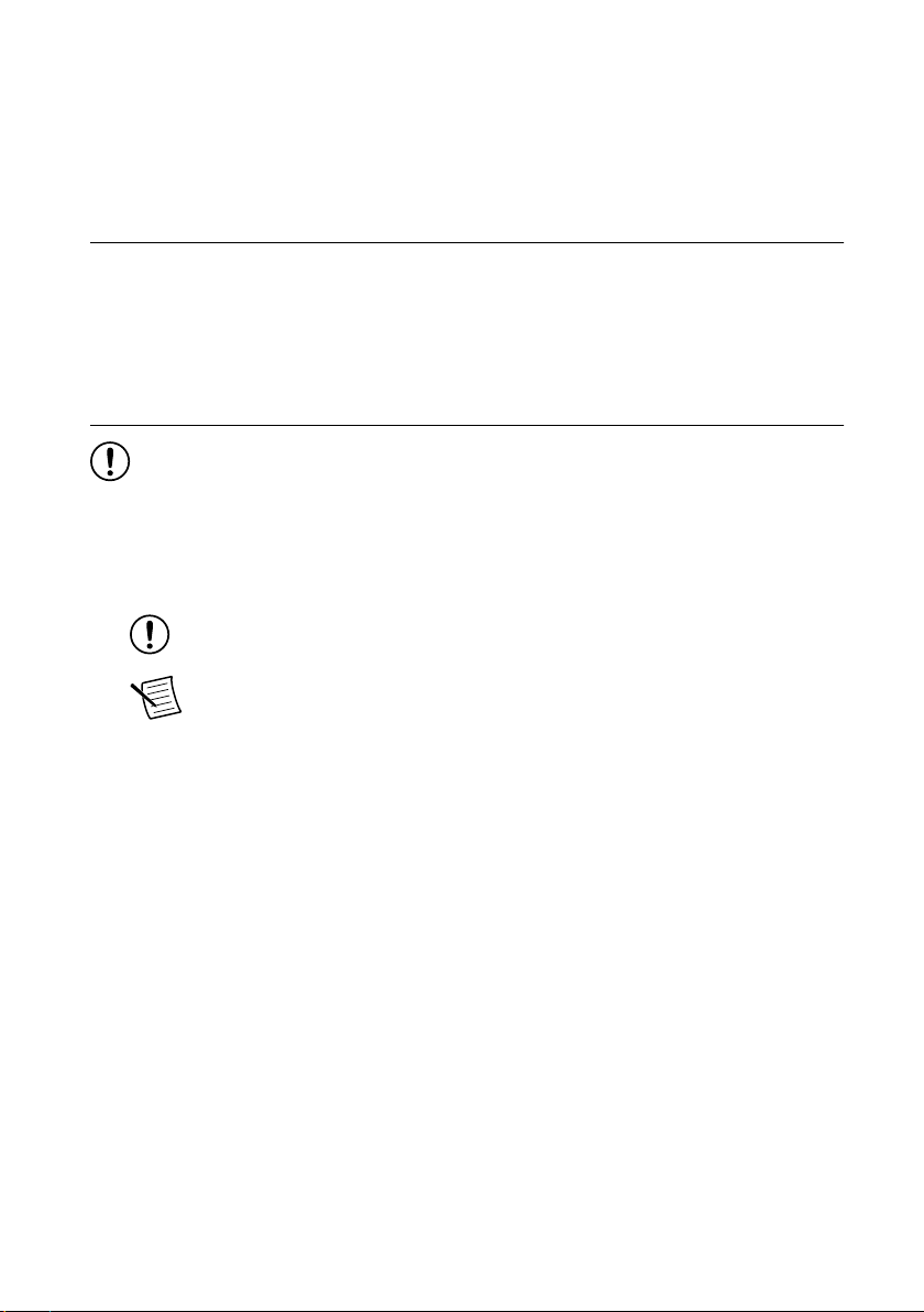
Verifying the Kit Contents
1
2
6
9
10
87
SD
NSITIVE
NI PXIe-5820
Vector Signal Transceiver
Baseband IQ, 1.25 GS/s
PFI 0
DIO
I+
I–
Q+
Q–
I+
I–
Q+
Q–
REF
OUT
REF
IN
ACCESS ACTIVE
I/Q IN
100 Ω DIFF
I/Q OUT
100 Ω DIFF
50 Ω
50 Ω
IF IN/O
RESERVE
NI PXIe-3621
Vector Signal Up/Down Converter
5-12
ACCESS ACTIVE
I/Q
IN
100 Ω
DIFF
I/Q
OUT
100 Ω
DIFF
Q+
Q–
I+
I–
Q+
Q–
LO2
IN
OUT
I+
I–
RESERVED
ALL COAXIAL PORTS 50 Ω
ESD
SENSITIVE
3 4 5
1. PXIe-3621 Module
2. PXIe-5820 Module
3. SMA (m)-to-SMA (m) Cable, 12 in.
4. MMPX (m)-to-MMPX (m) Cable, 200 mm
5. MMPX (m)-to-MMPX (m) Cable, 152 mm (x8)
6. Screwdriver, Part Number 772006-01
7. Maintain Forced-Air Cooling Note to Users
8. PXIe-5830 Getting Started Guide
9. PXIe-3621 Safety, Environmental, and Regulatory
Information
10. PXIe-5820 Safety, Environmental, and Regulatory
Information
Other Equipment
There are required items not included in your kit that you need to install or operate the
PXIe-5830. Your application may require additional items not included in your kit to install or
operate your hardware.
Required Items
• A PXI Express chassis and chassis documentation. To ensure specifications are valid, NI
recommends using the PXIe-1095 Chassis or PXIe-1092 Chassis for your hardware. For
more information about compatible chassis options, refer to ni.com.
• A PXI Express embedded controller or MXI controller system that meets the system
requirements specified in this guide and chassis documentation.
Optional Items
• A 0.9 N · m (8 lb · in.) calibrated torque wrench, 5/16 in. (NI part number 751120-01).
PXIe-5830 Getting Started Guide | © National Instruments | 3
Page 4
Preparing the Environment
Ensure that the environment you are using the PXIe-5830 in meets the following
specifications.
Operating ambient temperature 0 °C to 45 °C
Operating relative humidity 10% to 90%, noncondensing (IEC 60068-2-56)
Maximum altitude 2,000 m (800 mbar) (at 25 °C ambient
temperature)
Pollution Degree 2
Indoor use only.
Notice Clean the hardware with a soft, nonmetallic brush or lint free cloth. Make
sure that the hardware is completely dry and free from contaminants before returning
it to service.
Note Refer to the PXIe-5830 Specifications at ni.com/manuals for complete
specifications.
4 | ni.com | PXIe-5830 Getting Started Guide
Page 5

Choosing and Installing the Software
Software Options
NI provides three software options for programming the PXIe-5830—RFmx, NI-RFSA and
NI-RFSG instrument driver software.
Table 1. PXIe-5830 Software Options
Software
Option
Description Use Case
RFmx Provides a single-handle instrument
driver with built-in measurements.
You can use instrument driver
FPGA extensions to customize the
device FPGA using precompiled
bitfiles.
NI-RFSA and
NI-RFSG
instrument
driver
Related Information
Refer to the RFmx SpecAn Help, the RFmx Demod Help, the NI RF Vector Signal Analyzers
Help, or the NI RF Signal Generators Help for more information about using the RFmx, NIRFSA, and NI-RFSG instrument driver FPGA extensions.
The NI-RFSA and NI-RFSG APIs
each provide a fixed API for
interacting with your hardware.
NI-RFSA and NI-RFSG provide
standard IVI-based functionality
needed for most vector signal
analyzer and vector signal generator
applications.
You can use NI-RFSA and
NI-RFSG instrument driver FPGA
extensions to customize the device
FPGA using precompiled bitfiles.
Use RFmx SpecAn to perform spectral
measurements.
Use RFmx Demod to perform
modulation quality measurements,
such as EVM.
Use RFmx personalities to perform
physical layer analysis on supported
communications and connectivity
signals.
Use NI-RFSA to create custom
measurements or applications that
require I/Q data.
Use NI-RFSG to generate CW or
modulated waveforms.
Use NI-RFSA and NI-RFSG with the
NI Modulation Toolkit to develop
software-defined radio transmitters and
receivers.
Use NI-RFSG with the NI Modulation
Toolkit to create and generate
modulated signals to test receivers.
Installing the Software
You must be an Administrator to install NI software on your computer.
1. Install an ADE, such as LabVIEW or LabWindows™/CVI™.
PXIe-5830 Getting Started Guide | © National Instruments | 5
Page 6

2. Install the driver software using NI Package Manager or by inserting your driver software
media into your computer.
If you do not already have NI Package Manager installed, visit ni.com/r/NIPMDownload
to download NI Package Manager. Refer to the NI Package Manager Manual for more
information about installing, removing, and upgrading NI software using NI Package
Manager.
3. Follow the instructions in the installation prompts.
Note Windows users may see access and security messages during
installation. Accept the prompts to complete the installation.
4. When the installer completes, select Restart in the dialog box that prompts you to restart,
shut down, or restart later.
Installing the PXIe-5830
Notice To prevent damage to the PXIe-5830 caused by ESD or contamination,
handle the module using the edges or the metal bracket.
You must install the software before installing the hardware.
Before you install the hardware, refer to the guidelines in the Maintain Forced-Air Cooling
Note to Users included with the module to ensure that the device can cool itself effectively.
To use the included cables, you must install the PXIe-5820 immediately to the left of the
PXIe-3621.
1. Ensure the AC power source is connected to the chassis before installing the module.
The AC power cord grounds the chassis and protects it from electrical damage while you
install the module.
2. Power off the chassis.
3. Inspect the slot pins on the chassis backplane for any bends or damage prior to
installation. Do not install a module if the backplane is damaged.
4. Remove the black plastic covers from all the captive screws on the module front panel.
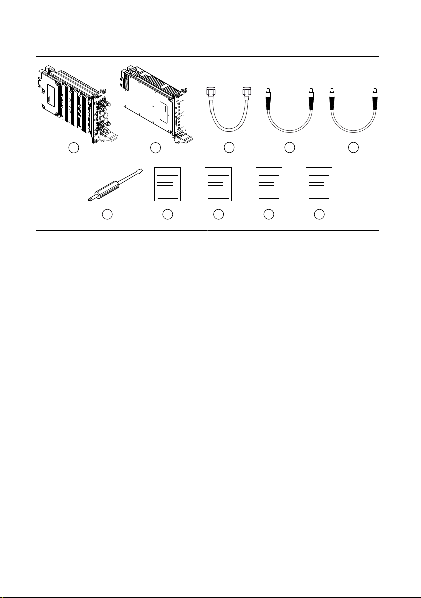
5. Identify a supported slot in the chassis. The following figure shows the symbols that
indicate the slot types.
6 | ni.com | PXIe-5830 Getting Started Guide
Page 7
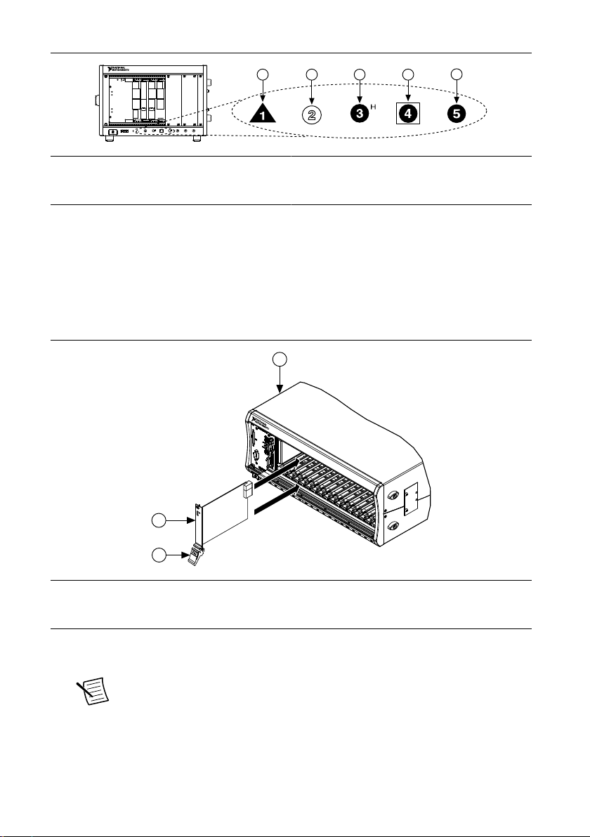
Figure 1. Chassis Compatibility Symbols
NI PXIe-1062Q
1
2 3
4
5
2
3
NI PXIe-1075
1
1. PXI Express System Controller Slot
2. PXI Peripheral Slot
3. PXI Express Hybrid Peripheral Slot
4. PXI Express System Timing Slot
5. PXI Express Peripheral Slot
The modules that comprise the PXIe-5830 can be placed in PXI Express peripheral slots,
PXI Express hybrid peripheral slots, or PXI Express system timing slots.
6. Touch any metal part of the chassis to discharge static electricity.
7. Ensure that the ejector handle is in the downward (unlatched) position.
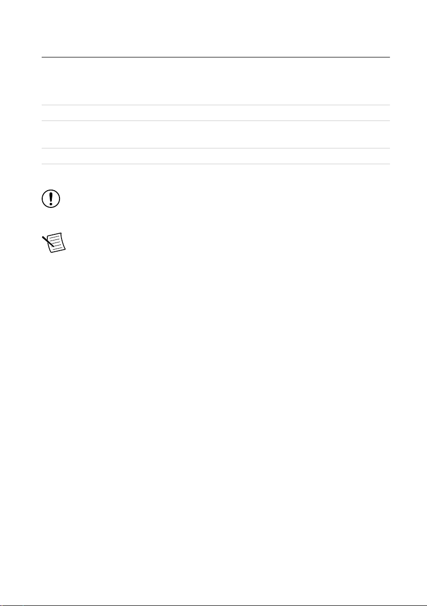
8. Place the module edges into the module guides at the top and bottom of the chassis. Slide
the module into the slot until it is fully inserted.
Figure 2. Module Installation
1. Chassis
2. Hardware Module
3. Ejector Handle in Downward (Unlatched) Position
9. Latch the module in place by pulling up on the ejector handle.
10. Secure the module front panel to the chassis using the front-panel mounting screws.
Note Tightening the top and bottom mounting screws increases mechanical
stability and also electrically connects the front panel to the chassis, which can
improve the signal quality and electromagnetic performance.
11. Cover all empty slots using EMC filler panels or fill using slot blockers to maximize
cooling air flow, depending on your application.
PXIe-5830 Getting Started Guide | © National Instruments | 7
Page 8

12. Power on the chassis.
Related Information
Installing the Software on page 5
Interconnecting the PXIe-5830 Modules
Take the following considerations into account when interconnecting the PXI Express modules
that comprise the PXIe-5830.
• Inspect all RF connectors before attaching mating cables. Clean with dry compressed air,
if necessary, to remove any contaminants that may be present.
• Position RF cables with instrument connectors to ensure center pins are straight and
aligned before mating.
• Press MMPX connectors until they noticeably snap into place.
• For all threaded RF connectors (SMA and SMA 27 GHz), engage and finger-tighten the
connector nuts. The connector nuts should thread easily without binding, but if not,
ensure the connector is straight and that center pins have not been damaged.
• Carefully complete tightening all threaded RF connectors to 0.9 N · m (8 lb · in) using an
appropriate torque wrench (not included) or torque screwdriver and driver bit. Tighten
only until the wrench clicks.
Notice Incorrect torque at SMA connections can damage device connectors and
degrade signal fidelity.
Connecting the PXIe-5820 and PXIe-3621
Complete the following steps for the baseband signal connections and Reference Clock
connection, as shown in the following figure.
8 | ni.com | PXIe-5830 Getting Started Guide
Page 9
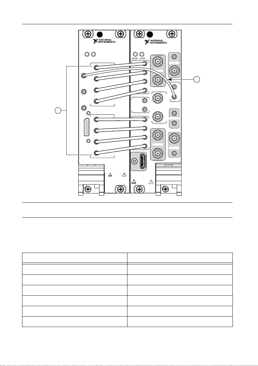
Figure 3. PXIe-5830 Equipment Setup
NI PXIe-5820
Vector Signal Transceiver
Baseband IQ, 1.25 GS/s
REF
OUT
I/Q OUT
PFI 0
DIO
REF
IN
I+
I–
Q+
Q–
ACCESS ACTIVE
ESD
SENSITIVE
50 Ω
100 Ω DIFF
I/Q IN
I+
I–
Q+
Q–
100 Ω DIFF
50 Ω
RESERVED
RESERVED
RESERVED
RESERVED
REF
OUT
IN
I/Q
IN
100 Ω
DIFF
OUT
IN
I/Q
OUT
100 Ω
DIFF
LO2
I+
I
–
Q+
Q
–
I+
I
–
Q+
Q
–
ESD
SENSITIVE
ALL COAXIAL PORTS 50 Ω
0
1
IF IN/OUT
PXIe-3621
Vector Signal Up/Down Converter
5–12 GHz
RESERVED
RESERVED
RESERVED
RESERVED
2
1
1. MMPX (m)-to-MMPX (m) Cable, 152 mm
2. MMPX (m)-to-MMPX (m) Cable, 200 mm
1. Complete the following baseband signal cable connections between the PXIe-5820 and
PXIe-3621 front panels using the included eight 152 mm MMPX (m)-to-MMPX (m)
cables for transmit and receive I/Q signals.
PXIe-5820 Connector PXIe-3621 Connector
Table 2. Baseband Signal Cable Connections
I/Q OUT I+ I/Q IN I+
I/Q OUT I- I/Q IN I-
I/Q OUT Q+ I/Q IN Q+
I/Q OUT Q- I/Q IN Q-
I/Q IN I+ I/Q OUT I+
I/Q IN I- I/Q OUT I-
PXIe-5830 Getting Started Guide | © National Instruments | 9
Page 10

Table 2. Baseband Signal Cable Connections (Continued)
PXIe-5820 Connector PXIe-3621 Connector
I/Q IN Q+ I/Q OUT Q+
I/Q IN Q- I/Q OUT Q-
2. Use the 200 mm MMPX (m)-to-MMPX (m) cable to connect the PXIe-5820 REF IN
front panel connector to the PXIe-3621 REF OUT front panel connector.
This completes the Reference Clock connection.
Direct Connections to the PXIe-5830
The PXIe-5830 is a precision RF instrument that is sensitive to ESD and transients. Ensure
you are making proper direct connections to the PXIe-5830 to avoid damaging the hardware.
Notice Apply external signals only while the hardware is powered on. Applying
external signals while the hardware is powered off may cause damage.
• Ensure you are properly grounded when manipulating cables or antennas connected to the
instrument.
• If you are using noninsulated devices, such as an RF antenna, ensure the devices are
maintained in a static-free environment.
• If you are using an active device, such as a preamplifier or switch routed to the
PXIe-5830, ensure that the device cannot generate signal transients greater than the RF
and DC specifications of the PXIe-5830.
Configuring the PXIe-5830 in MAX
Use Measurement & Automation Explorer (MAX) to configure your NI hardware. MAX
informs other programs about which NI hardware products are in the system and how they are
configured. MAX is automatically installed with NI-RFSA, NI-RFSG, and RFmx.
1. Launch MAX.
2. In the configuration tree, expand Devices and Interfaces to see the list of installed NI
hardware.
Installed modules appear under the name of their associated chassis.
3. Expand your Chassis tree item.
MAX lists all modules installed in the chassis. Your default names may vary.
Note If you do not see your module listed, press <F5> to refresh the list of
installed modules. If the module is still not listed, power off the system, ensure
the module is correctly installed, and restart.
4. Record the identifier MAX assigns to the PXIe-3621. Use this identifier when
programming the PXIe-5830.
10 | ni.com | PXIe-5830 Getting Started Guide
Page 11

5. Associate the hardware modules that comprise your instrument.
a) Select the PXIe-3621 that is identified as not configured in the configuration tree.
b) In the Associated Devices section, select the PXIe-5820 from the Baseband list.
c) Click Save in the MAX toolbar.
Note Module associations may be lost when you move the modules to
different chassis slots.
6. Self-test the hardware by selecting the item in the configuration tree and clicking Self-
Test in the MAX toolbar. Repeat this step for all modules in your PXIe-5830 system.
The MAX self-test performs a basic verification of hardware resources.
Related Information
Interconnecting the PXIe-5830 Modules on page 8
Troubleshooting on page 17
If an issue persists after you complete a troubleshooting procedure, contact NI technical
support or visit ni.com/support.
Self-Calibration
Self-calibration adjusts the PXIe-5830 for variations in the module environment using onboard
power detectors.
The PXIe-5830 modules are externally calibrated at the factory; however, you should perform
a self-calibration in any of the following situations:
• After first installing and interconnecting your PXIe-5830 instrument
• After any module in the chassis is installed, uninstalled, or moved
• After inter-module cabling has been changed, reconnected, or repositioned
• After changing controllers, computers, or reinstalling the driver software
• When the system is in an environment where the ambient temperature varies or the
module temperature has drifted more than ±5 °C from the temperature at the last selfcalibration
• To periodically adjust for small performance drifts that occur with product aging
Note To ensure specifications before you use the instrument or perform self-
calibration, power on the PXI Express chassis; set the chassis fan speeds to AUTO
or HIGH, depending on the chassis; wait for the operating system to completely
load; and then allow the instrument to warm up for 30 minutes.
Note Ensure that any connected external hardware is in an idle state and not
transmitting during self-calibration. It is not recommended to perform selfcalibration while connected in direct loopback configurations.
Performing a Self-Calibration Using NI-RFSA
NI recommends you perform the self-calibration using the NI-RFSA example when you selfcalibrate the module.
PXIe-5830 Getting Started Guide | © National Instruments | 11
Page 12

1. Select Start»All Programs»National Instruments»LabVIEW to launch LabVIEW.
2. Launch the Example Finder and navigate to the example.
a) Select Hardware Input and Output»Modular Instruments»NI-RFSA»Utilities»
RFSA Self Calibration.
b) Open the example.
3. Complete the following steps to configure the example:
a) Select the device identifier assigned to the PXIe-3621 in MAX in the [Resource
Name] drop-down menu.
b) Set Clock Source to OnboardClock.
c) Set Self Calibration Step Operations to Perform All Self Calibration Steps.
4. Run the VI.
12 | ni.com | PXIe-5830 Getting Started Guide
Page 13

Locating the Software and Examples
Software Locations
Table 3. Location of PXIe-5830 Software Options
Software
Option
RFmx LabVIEW Available on the LabVIEW Functions palette at
LabWindows/CVI RFmx functions are available from the
Microsoft Visual C/C++ Use the header files located in the <NIDir>\Shared
ADE Location
Measurement I/O»NI-RFmx.
LabWindows/CVI Library menu at Library»RFmx
SpecAn Library and Library»RFmx Demod
Library.
\ExternalCompilerSupport\C\include
directory and import library files located in one of the
following directories:
• Windows 10 (32-bit)/8.1 (32-bit)/7 (32-bit)-
<NIDir>\Shared
\ExternalCompilerSupport\C\include
• Windows 10 (64-bit)/8.1 (64-bit)/7 (64-bit) :
– 32-bit installation-<NIDir>\Shared
\ExternalCompilerSupport\C
\lib32\msvc
– 64-bit installation-<NIDir>\Shared
\ExternalCompilerSupport\C
\lib64\msvc
where <NIDir> is one of the following locations:
• Windows 10 (32-bit)/8.1 (32-bit)/7 (32-bit)-
Program Files\National Instruments
• Windows 10 (64-bit)/8.1 (64-bit)/7 (64-bit)-
Program Files (x86)\National
Instruments
Microsoft .NET For the location of .NET class libraries, refer to the
installed RFmx readme.
PXIe-5830 Getting Started Guide | © National Instruments | 13
Page 14

Table 3. Location of PXIe-5830 Software Options (Continued)
Software
Option
ADE Location
NI-RFSA LabVIEW Available on the LabVIEW Functions palette at
Measurement I/O»NI-RFSA.
LabWindows/CVI Available in the <IVIROOTDIR32>\Drivers\niRFSA
directory, where <IVIROOTDIR32> is one of the
following locations:
• Windows 10 (32-bit)/8.1 (32-bit)/7 (32-bit)-
Program Files\IVI Foundation\IVI
• Windows 10 (64-bit)/8.1 (64-bit)/7 (64-bit)-
Program Files (x86)\IVI Foundation
\IVI
Microsoft Visual C/C++ Use the header files located in the <IVIROOTDIR32>
\Include directory and import library files located in
the <IVIROOTDIR32>\Lib directory, where
<IVIROOTDIR32> is one of the following directories:
• Windows 10 (32-bit)/8.1 (32-bit)/7 (32-bit)-
Program Files\IVI Foundation\IVI
• Windows 10 (64-bit)/8.1 (64-bit)/7 (64-bit)-
Program Files (x86)\IVI Foundation
\IVI
Microsoft .NET Use the NI-RFSA .NET class library by adding a
14 | ni.com | PXIe-5830 Getting Started Guide
reference to
NationalInstruments.ModularInstruments.
NIRfsa.Fx40 or
NationalInstruments.ModularInstruments.
NIRfsa.Fx45 and any dependent class libraries from
within the Solution Explorer in Visual Studio.
Page 15

Table 3. Location of PXIe-5830 Software Options (Continued)
Software
Option
ADE Location
NI-RFSG LabVIEW Available on the LabVIEW Functions palette at
Measurement I/O»NI-RFSG.
LabWindows/CVI Available in the <IVIROOTDIR32>\Drivers\niRFSG
directory, where <IVIROOTDIR32> is one of the
following locations:
• Windows 10 (32-bit)/8.1 (32-bit)/7 (32-bit)-
Program Files\IVI Foundation\IVI
• Windows 10 (64-bit)/8.1 (64-bit)/7 (64-bit)-
Program Files (x86)\IVI Foundation
\IVI
Microsoft Visual C/C++ Use the header files located in the <IVIROOTDIR32>
\Include directory and import library files located in
the <IVIROOTDIR32>\Lib directory, where
<IVIROOTDIR32> is one of the following directories:
• Windows 10 (32-bit)/8.1 (32-bit)/7 (32-bit)-
Program Files\IVI Foundation\IVI
• Windows 10 (64-bit)/8.1 (64-bit)/7 (64-bit)-
Program Files (x86)\IVI Foundation
\IVI
Microsoft .NET Use the NI-RFSG .NET class library by adding a
reference to
NationalInstruments.ModularInstruments.
NIRfsg.Fx40 or
NationalInstruments.ModularInstruments.
NIRfsg.Fx45 and any dependent class libraries from
within the Solution Explorer in Visual Studio.
Programming Examples Locations
Using the NI Example Finder
If you are using RFmx, NI-RFSA, or NI-RFSG with LabVIEW or LabWindows/CVI, use the
NI Example Finder to locate programming examples.
1. Launch LabVIEW or LabWindows/CVI.
2. Select Help»Find Examples to open the NI Example Finder.
PXIe-5830 Getting Started Guide | © National Instruments | 15
Page 16

3. Navigate to Hardware Input and Output»Modular Instruments.
4. Open the example that best matches your application requirements.
Using Microsoft Visual C/C++
If you are using RFmx or NI-RFSA with Microsoft Visual C/C++, locate examples in the
following directories.
Table 4. Location of Microsoft Visual C/C++ Programming Examples
Software Option Examples Location
RFmx <NIDocDir>\RFmx\Demod\Examples
<NIDocDir>\RFmx\SpecAn\Examples
where <NIDocDir> is the Users\Public\Public Documents
\National Instruments directory.
NI-RFSA <NIDocDir>\NI-RFSA\examples
where <NIDocDir> is the Users\Public\Public Documents
\National Instruments directory.
Making a First Measurement
You can verify proper installation and configuration of your instrument by making a
measurement using the NI-RFSG and RFmx Soft Front Panels (SFPs).
1. Connect the PXIe-5830 IF IN/OUT 0 and IF IN/OUT 1 ports as appropriate for your
application.
2. Select Start»All Programs»National Instruments»NI-RFSG»NI-RFSG Soft Front
Panel to launch the NI-RFSG SFP.
3. Select the device identifier assigned to the PXIe-3621 in MAX in the Device drop-down
menu.
4. Set the RF Frequency to 5 GHz.
5. Click the RF On/Off button to generate a continuous wave (CW) tone RF signal at the IF
output terminal of your instrument.
6. Select Start»All Programs»National Instruments»RFmx SpecAn»RFmx Soft Front
Panel to launch the RFmx SFP.
7. Select the device identifier assigned to the PXIe-3621 in MAX in the Device drop-down
menu.
8. Set the Center Frequency to 5 GHz
9. Verify that the RFmx SFP is receiving the CW tone.
16 | ni.com | PXIe-5830 Getting Started Guide
Page 17

10. Close the RFmx SFP and NI-RFSG SFP.
Related Information
Interconnecting the PXIe-5830 Modules on page 8
Troubleshooting
If an issue persists after you complete a troubleshooting procedure, contact NI technical
support or visit ni.com/support.
What Should I Do if the PXIe-3621 Does Not Appear in MAX?
1. In the MAX configuration tree, expand Devices and Interfaces.
2. Expand the Chassis tree to see the list of installed hardware, and press <F5> to refresh
the list.
3. If the module is still not listed, power off the system, ensure that all hardware is correctly
installed, and restart the system.
4. Navigate to the Device Manager.
Operating System Description
Windows 10/8.1 Right-click the Start button, and select Device Manager.
Windows 7 Select Start»Control Panel»Device Manager.
5. Verify the PXIe-3621 appears in the Device Manager.
a) Under NI Modular Instruments, confirm that a PXIe-3621 entry appears.
Note If you are using a PC with a device for PXI remote control system,
under System Devices, also confirm that no error conditions appear for the
PCI-to-PCI Bridge.
b) If error conditions appear, reinstall the driver software and the PXIe-3621.
Why Is the ACCESS LED Off When the Chassis Is On?
The LEDs may not light until the device has been configured in MAX. Before proceeding,
verify that the PXIe-5830 appears in MAX.
If the module appears in MAX but the ACCESS LED fails to light after you power on the
chassis, a problem may exist with the chassis power rails, the hardware module, or the LED.
Notice Apply external signals only while the hardware is powered on. Applying
external signals while the hardware is powered off may cause damage.
1. Disconnect any signals from the PXI Express module front panel.
2. Power off the PXI Express chassis.
PXIe-5830 Getting Started Guide | © National Instruments | 17
Page 18

3. Remove the module from the PXI Express chassis and inspect it for damage. Do not
reinstall a damaged device.
4. Install the module in a different PXI Express chassis slot from which you removed it.
5. Power on the PXI Express chassis.
6. Restart your computer.
7. Verify that the device appears in MAX.
What Should I Do if the PXIe-5830 Fails the Self-Test?
1. Restart the system.
2. Launch MAX, and perform the self-test again.
3. Power off the chassis.
4. Reinstall the failed module in a different slot.
5. Power on the chassis.
6. Perform the self-test again.
What Should I Do if the Instrument Does Not Initialize?
Failure to initialize may indicate a problem with module interconnections or with MAX. If the
niRFSA Initialize VI or niRFSG Initialize VI returns an error and the PXIe-5830 fails to
initialize, complete the following steps:
1. Reconnect the PXIe-5830 front panel cables securely.
2. Power on your system and run the MAX configuration and self-test procedures.
18 | ni.com | PXIe-5830 Getting Started Guide
Page 19

Hardware Connectors and Indicators
NI PXIe-5820
Vector Signal Transceiver
Baseband IQ , 1.25 GS/s
REF
OUT
I/Q OUT
PFI 0
DIO
REF
IN
I+
I–
Q+
Q–
ACCESS ACTIVE
ESD
SENSITIVE
50 Ω
100 Ω DIFF
I/Q IN
I+
I–
Q+
Q–
100 Ω DIFF
50 Ω
PXIe-5820 Front Panel and LEDs
Front Panel and LEDs
Connector Description Connector Type
REF IN Input connector that allows for the use of an external 10 MHz
Reference Clock.
Table 5. General Connector Descriptions
MMPX (f)
REF OUT Output connector that can export a 10 MHz Reference Clock. MMPX (f)
PXIe-5830 Getting Started Guide | © National Instruments | 19
Page 20

Table 5. General Connector Descriptions (Continued)
Connector Description Connector Type
PFI 0 Programmable-function digital I/O (DIO) connector for use
MMPX (f)
with triggers or events.
DIO Multi-signal DIO connector that provides access to FPGA
Nano-Pitch I/O
multi-gigabit transceivers (MGTs) and general purpose
LVCMOS signals.
Table 6. I/Q Connector Descriptions
Connector Description Connector Type
I/Q OUT I+ Output connector for I+ signals. MMPX (f)
I- Output connector for I- signals. MMPX (f)
Q+ Output connector for Q+ signals. MMPX (f)
Q- Output connector for Q- signals. MMPX (f)
I/Q IN I+ Input connector for I+ signals. MMPX (f)
I- Input connector for I- signals. MMPX (f)
Q+ Input connector for Q+ signals. MMPX (f)
Q- Input connector for Q- signals. MMPX (f)
20 | ni.com | PXIe-5830 Getting Started Guide
Page 21

Table 7. LED Indicators
LED Indications
ACCESS Indicates the basic hardware status of the device.
Off—The device is not yet functional or has detected a problem with a PXI
Express power rail.
Amber—The device is being accessed. Accessed means that you are writing to the
device setup registers to control the device, reading from the device to monitor the
device status, or transferring data to/from the device.
Green—The device is controllable through the software.
ACTIVE Off—The device is idle.
Solid green—The device is generating a waveform.
Dim amber—The device is waiting for an acquisition Reference Trigger.
Solid amber—The device is acquiring a waveform.
Solid red—The device has detected an error. The LED remains red until the error
condition is removed.
Note The indicators are listed in increasing order of priority. For
example, if you are generating a waveform using NI-RFSG and
waiting on an acquisition Reference Trigger in NI-RFSA, the LED is
dim amber.
PXIe-5830 Getting Started Guide | © National Instruments | 21
Page 22

DIO Connector Pinout
A1
A2
A3
A4
A5
A6
A7
A8
A9
A10
A11
A12
A13
A14
A15
A16
A17
A18
A19
A20
A21
B1
B2
B3
B4
B5
B6
B7
B8
B9
B10
B11
B12
B13
B14
B15
B16
B17
B18
B19
B20
B21
Reserved
GND
MGT Rx+ 0
MGT Rx– 0
GND
MGT Rx+ 1
MGT Rx– 1
GND
DIO 4
DIO 5
GND
MGT REF+ / DIO 0
GND
MGT Rx+ 2
MGT Rx– 2
GND
MGT Rx+ 3
MGT Rx– 3
GND
5.0 V
5.0 V
GND
MGT Tx+ 0
MGT Tx– 0
GND
MGT Tx+ 1
MGT Tx– 1
GND
DIO 6
DIO 7
GND
DIO 2
DIO 3
GND
MGT Tx+ 2
MGT Tx– 2
GND
MGT Tx+ 3
MGT Tx– 3
GND
Reserved
22 | ni.com | PXIe-5830 Getting Started Guide
Page 23

PXIe-3621 Front Panel and LEDs
RESERVED
RESERVED
RESERVED
RESERVED
REF
OUT
IN
I/Q
IN
100 Ω
DIFF
OUT
IN
I/Q
OUT
100 Ω
DIFF
LO2
I+
I
–
Q+
Q
–
I+
I
–
Q+
Q
–
ESD
SENSITIVE
ALL COAXIAL PORTS 50 Ω
0
1
IF IN/OUT
PXIe-3621
Vector Signal Up/Down Converter
5–12 GHz
RESERVED
RESERVED
RESERVED
RESERVED
I/Q IN I+ Input connector for I+ signals. MMPX (f)
Table 8. I/Q Connector Descriptions
Connector Description Connector Type
I- Input connector for I- signals. MMPX (f)
Q+ Input connector for Q+ signals. MMPX (f)
Q- Input connector for Q- signals. MMPX (f)
PXIe-5830 Getting Started Guide | © National Instruments | 23
Page 24

Table 8. I/Q Connector Descriptions (Continued)
Connector Description Connector Type
I/Q OUT I+ Output connector for I+ signals. MMPX (f)
I- Output connector for I- signals. MMPX (f)
Q+ Output connector for Q+ signals. MMPX (f)
Q- Output connector for Q- signals. MMPX (f)
Table 9. General Connector Descriptions
Connector Description Connector Type
LO2 IN Input connector for the external local oscillator signal
MMPX (f)
used for the up and down conversion between
baseband and IF.
OUT Output connector for the local oscillator signal used
MMPX (f)
for the up and down conversion between baseband
and IF.
IF IN/OUT 0 IF0 bi-directional connector for both input and output. SMA 27 GHz (f)
1 IF1 bi-directional connector for both input and output. SMA 27 GHz (f)
REF IN Input connector for the Reference Clock. MMPX (f)
OUT Output connector for the Reference Clock. MMPX (f)
RESERVED Reserved connectors are not enabled for use on the
—
PXIe-5830 and should remain capped with 50 Ω
terminators to ensure specified instrument
performance.
24 | ni.com | PXIe-5830 Getting Started Guide
Page 25

Table 10. LED Indicators
LED Indications
ACCESS Indicates the basic hardware status of the module.
• OFF—The driver software has not yet loaded, or the module exceeded
approved operating temperature and thermal shutdown occurred or has
detected a problem with a power rail.
• AMBER—The module is being accessed. Accessed means that the device
setup registers are being written to in order to control the device.
• GREEN—The module is ready to be programmed by software.
ACTIVE
• OFF—The module is idle.
• RED—The module detected an error state.
PXIe-5830 Getting Started Guide | © National Instruments | 25
Page 26

Where to Go Next
EXPLORE LEARN CREATE
DISCOVER
*This item is also installed with the driver software.
The VST device information is also located in the NI RF Vector Signal Analyzer Help or the NI RF Signal Generators Help.
Learn LabVIEW Basics
the application development
environment (ADE)
for your application.
about hardware features
or review device
specifications.
custom applications with
an application programming
interface (API).
RFmx Examples*
NI-RFSA and NI-RFSG
Examples*
ni.com/vstgettingstarted
Services
ni.com/services
NI Community
ni.com/community
Support
ni.com/support
more about your products through ni.com.
Located online at ni.com/manuals
Located online at ni.com/gettingstarted
RF Solutions
ni.com/rf
PXIe-5830
Specifications*
NI RF Vector Signal
Transceivers Help*
†
†
Refer to the following figure for information about other product tasks and associated
resources for those tasks.
Tip The NI RF Vector Signal Transceivers Help, available at ni.com/manuals, is an
HTML version of a traditional user manual that includes detailed information about
RF fundamentals, device features, and programming for vector signal transceivers.
Worldwide Support and Services
The NI website is your complete resource for technical support. At ni.com/support, you have
access to everything from troubleshooting and application development self-help resources to
email and phone assistance from NI Application Engineers.
Visit ni.com/services for information about the services NI offers.
Visit ni.com/register to register your NI product. Product registration facilitates technical
support and ensures that you receive important information updates from NI.
26 | ni.com | PXIe-5830 Getting Started Guide
Page 27

NI corporate headquarters is located at 11500 North Mopac Expressway, Austin, Texas,
78759-3504. NI also has offices located around the world. For support in the United States,
create your service request at ni.com/support or dial 1 866 ASK MYNI (275 6964). For
support outside the United States, visit the Worldwide Offices section of ni.com/niglobal to
access the branch office websites, which provide up-to-date contact information.
PXIe-5830 Getting Started Guide | © National Instruments | 27
Page 28

Information is subject to change without notice. Refer to the NI Trademarks and Logo Guidelines at ni.com/trademarks for
information on NI trademarks. Other product and company names mentioned herein are trademarks or trade names of their
respective companies. For patents covering NI products/technology, refer to the appropriate location: Help»Patents in your
software, the patents.txt file on your media, or the National Instruments Patent Notice at ni.com/patents. You can find
information about end-user license agreements (EULAs) and third-party legal notices in the readme file for your NI product. Refer
to the Export Compliance Information at ni.com/legal/export-compliance for the NI global trade compliance policy and how
to obtain relevant HTS codes, ECCNs, and other import/export data. NI MAKES NO EXPRESS OR IMPLIED WARRANTIES AS
TO THE ACCURACY OF THE INFORMATION CONTAINED HEREIN AND SHALL NOT BE LIABLE FOR ANY ERRORS. U.S.
Government Customers: The data contained in this manual was developed at private expense and is subject to the applicable
limited rights and restricted data rights as set forth in FAR 52.227-14, DFAR 252.227-7014, and DFAR 252.227-7015.
© 2019 National Instruments. All rights reserved.
377946A-01 June 12, 2019
 Loading...