

Page 1

Serial
Serial Hardware and Software for Windows User Manual
PCI, PXI , PCMCIA, and AT
Serial Hardware
Serial Hardware and Software for Windows
December 2000 Edition
Part Number 322983A-01
Page 2

Support
Worldwide Technical Support and Product Information
ni.com
National Instruments Corporate Headquarters
11500 North Mopac Expressway Austin, Texas 78759-3504 USA Tel: 512 794 0100
Worldwide Offices
Australia 03 9879 5166, Austria 0662 45 79 90 0, Belgium 02 757 00 20, Brazil 011 284 5011,
Canada (Calgary) 403 274 9391, Canada (Ottawa) 613 233 5949, Canada (Québec) 514 694 8521,
China (Shanghai) 021 6555 7838, China (ShenZhen) 0755 3904939, Denmark 45 76 26 00,
Finland 09 725 725 11, France 01 48 14 24 24, Germany 089 741 31 30, Greece 30 1 42 96 427,
Hong Kong 2645 3186, India 91805275406, Israel 03 6120092, Italy 02 413091, Japan 03 5472 2970,
Korea 02 596 7456, Mexico 5 280 7625, Netherlands 0348 433466, New Zealand 09 914 0488,
Norway 32 27 73 00, Poland 0 22 528 94 06, Portugal 351 1 726 9011, Singapore 2265886, Spain 91 640 0085,
Sweden 08 587 895 00, Switzerland 056 200 51 51, Taiwan 02 2528 7227, United Kingdom 01635 523545
For further support information, see the Technical Support Resources appendix. To comment on the
documentation, send e-mail to techpubs@ni.com
© Copyright 1997, 2000 National Instruments Corporation. All rights reserved.
Page 3

Important Information
Warranty
The serial hardware is warranted against defects in materials and workmanship for a period of one year from the date of shipment,
as evidenced by receipts or other documentation. National Instruments will, at its option, repair or replace equipment that proves
to be defective during the warranty period. This warranty includes parts and labor.
The media on which you receive National Instruments software are warranted not to fail to execute programming instructions,
due to defects in materials and workmanship, for a period of 90 days from date of shipment, as evidenced by receipts or other
documentation. National Instruments will, at its option, repair or replace software media that do not execute programming
instructions if National Instruments receives notice of such defects during the warranty period. National Instruments does not
warrant that the operation of the software shall be uninterrupted or error free.
A Return Material Authorization (RMA) number must be obtained from the factory and clearly marked on the outside of
the package before any equipment will be accepted for warranty work. National Instruments will pay the shipping costs of
returning to the owner parts which are covered by warranty.
National Instruments believes that the information in this document is accurate. The document has been carefully reviewed
for technical accuracy. In the event that technical or typographical errors exist, National Instruments reserves the right to
make changes to subsequent editions of this document without prior notice to holders of this edition. The reader should consult
National Instruments if errors are suspected. In no event shall National Instruments be liable for any damages arising out of
or related to this document or the information contained in it.
E
XCEPT AS SPECIFIED HEREIN,NATIONAL INSTRUMENTS MAKES NO WAR RANTIES, EXPRESS OR IMPLIED, AND SPECIFICALLY DISCLAIMS ANY
WARRANTY OF MERCHANTABILITY OR FITNESS FOR A PARTICULAR PURPOSE
NEGLIGENCE ON THE PART OF
INSTRUMENTS WILL NOT BE LIABLE FOR DAMAGES RESULTING F ROM LOSS OF DATA, PROFITS, USE OF PRODUCTS, OR INCIDENTAL OR
CONSEQUENTIAL DAMAGES
apply regardless of the form of action, whether in contract or tort, including negligence. Any action against National Instruments
must be brought within one year after the cause of action accrues. National Instruments shall not be liable for any delay in
performance due to causes beyond its reasonable control. The warranty provided herein does not cover damages, defects,
malfunctions, or service failures caused by owner’s failure to follow the National Instruments installation, operation, or
maintenance instructions; owner’s modification of the product; owner’s abuse, misuse, or negligent acts; and power failure or
surges, fire, flood, accident, actions of third parties, or other events outside reasonable control.
NATIONAL INSTRUMENTS SHALL BE LIMITED TO THE AMOUNT THERETOFORE PAID BY THE CUSTOMER.NATIONAL
, EVEN IF ADVISED OF THE POSSIBILITY THEREOF. This limitation of the liability of National Instruments will
.CUSTOMER’S RIGHT TO RECOVER DAMAGES CAUSED BY FAULT OR
Copyright
Under the copyright laws, this publication may not be reproduced or transmitted in any form, electronic or mechanical, including
photocopying, recording, storing in an information retrieval system, or translating, in whole or in part, without the prior written
consent of National Instruments Corporation.
Trademarks
CVI™,LabVIEW™, National Instruments™,ni.com™,andPXI™are trademarks of National Instruments Corporation.
Product and company names mentioned herein are trademarks or trade names of their respective companies.
WARNING REGARDING USE OF NATIONAL INSTRUMENTS PRODUCTS
(1) NATIONAL INSTRUMENTS PRODUCTS ARE NOT DESIGNED WITHCOMPONENTS AND TESTING FOR A LEVEL
OF RELIABILITY SUITABLE FOR USE IN OR IN CONNECTION WITH SURGICAL IMPLANTS OR AS CRITICAL
COMPONENTS IN ANY LIFE SUPPORT SYSTEMS WHOSE FAILURE TO PERFORM CAN REASONABLY BE
EXPECTED TO CAUSE SIGNIFICANT INJURY TO A HUMAN.
(2) IN ANY APPLICATION, INCLUDING THE ABOVE, RELIABILITYOF OPERATION OFTHE SOFTWARE PRODUCTS
CAN BE IMPAIRED BY ADVERSE FACTORS, INCLUDING BUT NOT LIMITED TO FLUCTUATIONS IN ELECTRICAL
POWER SUPPLY, COMPUTER HARDWARE MALFUNCTIONS, COMPUTER OPERATING SYSTEM SOFTWARE
FITNESS, FITNESS OF COMPILERS AND DEVELOPMENT SOFTWARE USED TO DEVELOP AN APPLICATION,
INSTALLATION ERRORS, SOFTWARE AND HARDWARE COMPATIBILITY PROBLEMS, MALFUNCTIONS OR
FAILURES OF ELECTRONIC MONITORING OR CONTROL DEVICES, TRANSIENT FAILURES OF ELECTRONIC
SYSTEMS (HARDWARE AND/OR SOFTWARE), UNANTICIPATED USES OR MISUSES, OR ERRORS ONTHE PART OF
THE USER OR APPLICATIONS DESIGNER (ADVERSE FACTORS SUCH AS THESE ARE HEREAFTER
COLLECTIVELY TERMED “SYSTEM FAILURES”). ANY APPLICATION WHERE A SYSTEM FAILURE WOULD
CREATE A RISK OF HARM TO PROPERTY OR PERSONS (INCLUDING THE RISK OF BODILY INJURY AND DEATH)
SHOULD NOT BE RELIANT SOLELY UPON ONE FORM OF ELECTRONIC SYSTEM DUE TO THE RISK OF SYSTEM
FAILURE. TO AVOID DAMAGE, INJURY, OR DEATH, THE USER OR APPLICATION DESIGNER MUST TAKE
REASONABLY PRUDENT STEPS TO PROTECT AGAINST SYSTEM FAILURES, INCLUDING BUT NOT LIMITED TO
BACK-UP OR SHUT DOWN MECHANISMS. BECAUSE EACH END-USER SYSTEM IS CUSTOMIZED AND DIFFERS
FROM NATIONAL INSTRUMENTS' TESTING PLATFORMS AND BECAUSE A USER OR APPLICATION DESIGNER
MAY USE NATIONAL INSTRUMENTS PRODUCTS IN COMBINATION WITH OTHER PRODUCTS IN A MANNER NOT
EVALUATED OR CONTEMPLATED BY NATIONAL INSTRUMENTS, THE USER OR APPLICATION DESIGNER IS
ULTIMATELY RESPONSIBLE FOR VERIFYING AND VALIDATING THE SUITABILITY OF NATIONAL
INSTRUMENTS PRODUCTS WHENEVER NATIONAL INSTRUMENTS PRODUCTS ARE INCORPORATED IN A
SYSTEM OR APPLICATION, INCLUDING, WITHOUT LIMITATION, THE APPROPRIATE DESIGN, PROCESS AND
SAFETY LEVEL OF SUCH SYSTEM OR APPLICATION.
Page 4

Compliance
FCC/Canada Radio Frequency Interference Compliance*
Determining FCC Class
The Federal Communications Commission (FCC) has rules to protect wireless communications from interference.
The FCC places digital electronics into two classes. These classes are known as Class A (for use in industrialcommercial locations only) or Class B (for use in residential or commercial locations). Depending on where it is
operated, this product could be subject to restrictions in the FCC rules. (In Canada, the Department of
Communications (DOC), of Industry Canada, regulates wireless interference in much the same way.)
Digital electronics emit weak signals during normal operation that can affect radio, television, or other wireless
products. By examining the product you purchased, you can determine the FCC Class and therefore which of the two
FCC/DOC Warnings apply in the following sections. (Some products may not be labeled at all for FCC; if so, the
reader should then assume these are Class A devices.)
FCC Class A products only display a simple warning statement of oneparagraph in length regarding interference and
undesired operation. Most of our products are FCC Class A. The FCC rules have restrictions regarding the locations
where FCC Class A products can be operated.
FCC Class B products display either a FCC ID code, starting with the letters EXN,
or the FCC Class B compliance mark that appears as shown here on the right.
Consult the FCC web site
http://www.fcc.gov
FCC/DOC Warnings
This equipment generates and uses radio frequency energy and, if not installed and used in strict accordance with the
instructions in this manual and the CE Mark Declaration of Conformity**, may cause interference to radio and
television reception. Classification requirements are the same for the Federal Communications Commission (FCC)
and the Canadian Department of Communications (DOC).
Changes or modifications not expressly approved by National Instruments could void the user’s authority to operate
the equipment under the FCC Rules.
Class A
Federal Communications Commission
This equipment has been tested and found to comply with the limits for a Class A digital device, pursuant to part 15
of the FCC Rules. These limits are designed to provide reasonable protection against harmful interference when the
equipment is operated in a commercial environment. This equipment generates, uses, and can radiate radio frequency
energy and, if not installed and used in accordance with the instruction manual, may cause harmful interference to
radio communications. Operation of this equipment in a residential area is likely to cause harmful interference in
which case the user will be required to correct the interference at his own expense.
for more information.
Canadian Department of Communications
This Class A digital apparatus meets all requirements of the Canadian Interference-Causing Equipment Regulations.
Cet appareil numérique de la classe A respecte toutes les exigences du Règlement sur le matériel brouilleur du
Canada.
Class B
Federal Communications Commission
This equipment has been tested and found to comply with the limits for a Class B digital device, pursuant to part 15
of the FCC Rules. These limits are designed to provide reasonable protection against harmful interference in a
residential installation. This equipment generates, uses and can radiate radio frequency energy and, if not installed
and used in accordance with the instructions, may cause harmful interference to radio communications. However,
there is no guarantee that interference will not occur in a particular installation. If this equipment does cause harmful
interference to radio or television reception, which can be determined by turning the equipment off and on, the user
is encouraged to try to correct the interference by one or more of the following measures:
• Reorient or relocate the receiving antenna.
• Increase the separation between the equipment and receiver.
Page 5

• Connect the equipment into an outlet on a circuit different from that to which the receiver is connected.
• Consult the dealer or an experienced radio/TV technician for help.
Canadian Department of Communications
This Class B digital apparatus meets all requirements of the Canadian Interference-Causing Equipment Regulations.
Cet appareil numérique de la classe B respecte toutes les exigences du Règlement sur le matériel brouilleur du
Canada.
European Union - Compliance to EEC Directives
Readers in the EU/EEC/EEA must refer to the Manufacturer's Declaration of Conformity (DoC) for information**
pertaining to the CE Mark compliance scheme. The Manufacturer includes a DoC for most every hardware product
except for those bought for OEMs, if also available from an original manufacturer that also markets in the EU, or
where compliance is not required as for electrically benign apparatus or cables.
* Certain exemptions may apply in the USA, see FCC Rules §15.103 Exempted devices,and§15.105(c).
Also available in sections of CFR 47.
** The CE Mark Declaration of Conformity will contain important supplementary information and instructions
for the user or installer.
Page 6

Contents
About This Manual
Conventions ...................................................................................................................xiii
Related Documentation..................................................................................................xiv
Chapter 1
Introduction
How to Use This Manual ............................................................................................... 1-1
What You Need to Get Started ......................................................................................1-2
Optional Equipment.......................................................................................................1-3
Serial Hardware Overview.............................................................................................1-3
PCI Kits ...........................................................................................................1-3
PXI Kits...........................................................................................................1-4
PCMCIA Kits ..................................................................................................1-6
AT Kits ............................................................................................................ 1-6
NI-Serial Software Overview ........................................................................................1-8
Time-Saving Development Tools..................................................................................1-8
Chapter 2
PCI Serial Hardware Installation, Verification, and Configuration
Windows 2000 ............................................................................................................... 2-1
Install the Software..........................................................................................2-1
Install the Hardware ........................................................................................2-2
Verify the Installation......................................................................................2-4
Configure Communication Port Settings.........................................................2-5
Windows Me/9x.............................................................................................................2-9
Install the Software..........................................................................................2-9
Install the Hardware ........................................................................................2-10
Verify the Installation......................................................................................2-12
Configure Communication Port Settings.........................................................2-14
Windows NT..................................................................................................................2-18
Install the Software..........................................................................................2-18
Install the Hardware ........................................................................................2-18
Verify the Installation......................................................................................2-20
Configure Communication Port Settings.........................................................2-21
© National Instruments Corporation vii Serial Hardware and Software for Windows
Page 7

Contents
Chapter 3
PXI Serial Hardware Installation, Verification, and Configuration
Windows 2000............................................................................................................... 3-1
Install the Software ......................................................................................... 3-1
Install the Hardware........................................................................................3-2
Verify the Installation ..................................................................................... 3-4
Configure Communication Port Settings ........................................................ 3-5
Windows Me/9x............................................................................................................. 3-9
Install the Software ......................................................................................... 3-9
Install the Hardware........................................................................................3-10
Verify the Installation ..................................................................................... 3-11
Configure Communication Port Settings ........................................................ 3-13
Windows NT ................................................................................................................. 3-17
Install the Software ......................................................................................... 3-17
Install the Hardware........................................................................................3-17
Verify the Installation ..................................................................................... 3-19
Configure Communication Port Settings ........................................................ 3-20
Chapter 4
PCMCIA Serial Hardware Installation, Verification, and Configuration
Windows 2000............................................................................................................... 4-1
Install the Software ......................................................................................... 4-1
Install the Hardware........................................................................................4-2
Verify the Installation ..................................................................................... 4-3
Configure Communication Port Settings ........................................................ 4-5
Windows Me/9x............................................................................................................. 4-8
Install the Software ......................................................................................... 4-8
Install the Hardware........................................................................................4-9
Verify the Installation ..................................................................................... 4-10
Configure Communication Port Settings ........................................................ 4-13
Windows NT ................................................................................................................. 4-16
Install the NI-Serial Software ......................................................................... 4-16
Install the PCMCIA Serial Hardware .............................................................4-17
Verify the Installation ..................................................................................... 4-18
Configure Communication Port Settings ........................................................ 4-19
Serial Hardware and Software for Windows viii ni.com
Page 8

Chapter 5
AT Serial Hardware Installation, Verification, and Configuration
Windows 2000 ............................................................................................................... 5-1
Install the Software..........................................................................................5-1
Install the Hardware ........................................................................................5-2
Verify the Installation......................................................................................5-4
Configure Communication Port Settings.........................................................5-5
Windows Me/9x.............................................................................................................5-9
Install the Software..........................................................................................5-9
Install the Hardware ........................................................................................5-10
Verify the Installation......................................................................................5-12
Configure Communication Port Settings.........................................................5-14
Windows NT..................................................................................................................5-18
Installing the Microsoft PnP ISA Enabler Driver............................................5-18
Install the NI-Serial Software.......................................................................... 5-19
Install the Serial Hardware ..............................................................................5-19
Verify the Installation......................................................................................5-21
Configure Communication Port Settings.........................................................5-22
Chapter 6
Contents
Using Your Serial Hardware
General Programming Requirements.............................................................................6-1
Advanced Transceiver Control for the PCI/PXI/PCMCIA/AT-485 Boards .................6-1
Four-Wire Mode..............................................................................................6-2
Two-Wire Mode: DTR
Two-Wire Mode: DTR
Two-Wire Mode: TXRDY
Setting the Transceiver Control Mode ............................................................6-3
Setting the Transceiver Mode with DeviceIoControl......................................6-4
with Echo...................................................................6-2
Controlled..................................................................6-2
Auto Control ........................................................6-3
Appendix A
Connector Descriptions
Appendix B
Serial Port Information
Appendix C
Uninstalling the Hardware and Software
© National Instruments Corporation ix Serial Hardware and Software for Windows
Page 9

Contents
Appendix D
Troubleshooting and Common Questions
Appendix E
Specifications
Appendix F
Technical Support Resources
Glossary
Index
Figures
Figure 2-1. PCI Serial Board Installation ................................................................ 2-3
Figure 2-2. Device Manager for PCI Serial Board Ports......................................... 2-4
Figure 2-3. Port Settings Tab................................................................................... 2-7
Figure 2-4. Advanced Settings Dialog Box............................................................. 2-8
Figure 2-5. PCI Serial Board Installation ................................................................ 2-11
Figure 2-6. Device Manager Tab for PCI Serial Board Ports.................................. 2-13
Figure 2-7. Port Settings Tab................................................................................... 2-16
Figure 2-8. Advanced Port Settings Dialog Box ..................................................... 2-17
Figure 2-9. Installing the PCI Serial Board .............................................................2-19
Figure 2-10. niports Configuration Utility................................................................. 2-21
Figure 2-11. General Port Settings Dialog Box......................................................... 2-22
Figure 3-1. Installing the PXI Serial Board ............................................................. 3-3
Figure 3-2. Device Manager for PXI Serial Board Ports......................................... 3-4
Figure 3-3. Port Settings Tab................................................................................... 3-7
Figure 3-4. Advanced Settings Dialog Box............................................................. 3-8
Figure 3-5. Installing the PXI Serial Board ............................................................. 3-10
Figure 3-6. Device Manager for PXI Serial Board Ports......................................... 3-12
Figure 3-7. Port Settings Tab................................................................................... 3-15
Figure 3-8. Advanced Settings Dialog Box............................................................. 3-16
Figure 3-9. Installing the PXI Serial Board ............................................................. 3-18
Figure 3-10. niports Configuration Utility................................................................. 3-20
Figure 3-11. General Port Settings Dialog Box......................................................... 3-21
Figure 4-1. Inserting a PCMCIA Serial Card .......................................................... 4-3
Figure 4-2. Device Manager for PCMCIA Serial Card Ports.................................. 4-4
Serial Hardware and Software for Windows x ni.com
Page 10

Contents
Figure 4-3. Port Settings Tab ...................................................................................4-6
Figure 4-4. Advanced Settings Dialog Box .............................................................4-7
Figure 4-5. Inserting a PCMCIA Serial Card...........................................................4-10
Figure 4-6. Device Manager Ports List for PCMCIA Serial Card
Correctly Installed .................................................................................4-11
Figure 4-7. Port Settings Tab ...................................................................................4-14
Figure 4-8. Advanced Port Settings Dialog Box......................................................4-15
Figure 4-9. Inserting a PCMCIA Serial Card...........................................................4-17
Figure 4-10. niports Configuration Utility .................................................................4-19
Figure 4-11. General Port Settings Dialog Box .........................................................4-20
Figure 4-12. Resource Configuration Dialog Box for the PCMCIA-485 ..................4-22
Figure 4-13. Resource Configuration Dialog Box for the PCMCIA-485/2...............4-23
Figure 5-1. AT Serial Board Installation..................................................................5-3
Figure 5-2. Device Manager for AT Serial Board Ports ..........................................5-4
Figure 5-3. Port Settings Tab ...................................................................................5-7
Figure 5-4. Advanced Settings Dialog Box .............................................................5-8
Figure 5-5. AT Serial Board Installation..................................................................5-11
Figure 5-6. Device Manager Ports List for AT Serial Board
Correctly Installed .................................................................................5-13
Figure 5-7. Port Settings Tab ...................................................................................5-16
Figure 5-8. Advanced Port Settings Dialog Box......................................................5-17
Figure 5-9. AT Serial Board Installation..................................................................5-20
Figure 5-10. niports Configuration Utility .................................................................5-22
Figure 5-11. General Port Settings Dialog Box .........................................................5-23
Figure 5-12. PnP Port Configuration Dialog Box for the AT-232/4..........................5-25
Figure A-1. DB-9 Connector Pin Locations .............................................................A-2
Figure A-2. 10-Position Modular Jack Pin Locations...............................................A-3
Figure A-3. DB-25 Connector Pin Locations ...........................................................A-4
Figure A-4. Connecting the Cables to Your Four-Port PCI Serial Board................. A-5
Figure A-5. 68-Pin Connector Pin Locations............................................................A-6
Figure A-6. 100-Pin Connector Pin Locations..........................................................A-8
Figure B-1. Typical Full-Duplex System .................................................................B-4
Figure B-2. Typical Half-Duplex System .................................................................B-4
Figure B-3. Multidrop Network Using Terminating Resistors................................. B-5
Figure B-4. Transmission Line Using Bias Resistors...............................................B-6
Figure B-5. Straight-Through Cabling in a DTE-to-DCE Interface .........................B-7
Figure B-6. Null-Modem Cabling in a DTE-to-DTE Interface ................................B-7
Figure C-1. Selecting an Interface to Uninstall ........................................................C-2
Figure C-2. Selecting an Interface to Uninstall ........................................................C-4
Figure C-3. Selecting an Interface to Uninstall ........................................................C-5
© National Instruments Corporation xi Serial Hardware and Software for Windows
Page 11

Contents
Tables
Figure C-4. Selecting an Interface to Uninstall ........................................................ C-7
Figure C-5. Selecting an Interface to Uninstall ........................................................ C-9
Figure C-6. Selecting an Interface to Uninstall ........................................................ C-10
Figure C-7. Selecting an Interface to Uninstall ........................................................ C-12
Figure C-8. Selecting an Interface to Uninstall ........................................................ C-14
Figure C-9. Selecting an Interface to Uninstall ........................................................ C-16
Figure C-10. Selecting an Interface to Uninstall........................................................ C-17
Figure C-11. Selecting an Interface to Uninstall........................................................ C-19
Figure C-12. Selecting an Interface to Uninstall........................................................ C-21
Figure D-1. Selecting an Interface to Uninstall........................................................ D-2
Figure D-2. Ports List in Device Manager ............................................................... D-12
Figure D-3. Ports List in Device Manager ............................................................... D-14
Figure D-4. Multi-Function Adapter Class in the Device Manager ......................... D-17
Table 1-1. PXI Board Names and Descriptions .................................................... 1-5
Table 6-1. Transceiver Control Modes................................................................... 6-2
Table 6-2. Transceiver Mode Control Bytes .......................................................... 6-4
Table 6-3. DeviceIoControl Function Input Values .............................................. 6-5
Table A-1. DB-9 Pin Descriptions .......................................................................... A-2
Table A-2. 10-Position Modular Jack Pin Descriptions.......................................... A-3
Table A-3. DB-25 Pin Descriptions ........................................................................ A-4
Table A-4. 68-Pin Connector Pin Descriptions.......................................................A-7
Table A-5. 100-Pin Connector Pin Descriptions..................................................... A-9
Table B-1. RS-232, RS-422, and RS-485 Features................................................. B-1
Table D-1. Standard DOS-Based Addresses........................................................... D-15
Serial Hardware and Software for Windows xii ni.com
Page 12

About This Manual
This manual contains instructions to help you install and configure the
National Instruments serial hardware and the NI-Serial software for
Windows 2000/NT/Me/9x. This manual includes information about the
following serial hardware:
• PCI-232/2, PCI-232/4, PCI-232/8, PCI-232/16, PCI-485/2,
PCI-485/4, and PCI-485/8 boards in both isolated and nonisolated
versions
• PXI-8420 (two, four, eight, and 16 port), PXI-8421 (two, four, and
eight port), PXI-8422 (two and four port), and PXI-8423 (two and
four port)
• PCMCIA-232, PCMCIA-232/2, PCMCIA-232/4, PCMCIA-485, and
PCMCIA-485/2
• AT-232/2, AT-232/4, AT-485/2, and AT-485/4 boards in both isolated
and nonisolated versions
This manual assumes that you are already familiar with
Windows 2000/NT/Me/9x.
Conventions
The following conventions appear in this manual:
» The » symbol leads you through nested menu items and dialog box options
to a final action. The sequence File»Page Setup»Options directs you to
pull down the File menu, select the Page Setup item, and select Options
from the last dialog box.
♦ The ♦ symbol indicates that the following text applies only to a specific
product, a specific operating system, or a specific software version.
This icon denotes a note, which alerts you to important information.
This icon denotes a caution, which advises you of precautions to take to
avoid injury, data loss, or a system crash.
AT serial boards AT serial boards refers to all port versions of the AT serial boards.
© National Instruments Corporation xiii Serial Hardware and Software for Windows
Page 13

About This Manual
bold Bold text denotes items that you must select or click on in the software,
such as menu items and dialog box options. Bold text also denotes
parameter names.
DTR
italic Italic text denotes variables, emphasis, a cross reference, or an introduction
monospace
monospace bold
PCI serial boards PCI serial boards refers to all port versions of the PCI serial boards.
PCMCIA serial boards PCMCIA serial boards refers to all versions of the PCMCIA serial boards.
PXI serial boards PXI serial boards refers to all port versions of the PXI serial boards.
Signal names with an overscore, such as DTR, indicate that the signal is
active low.
to a key concept. This font also denotes text that is a placeholder for a word
or value that you must supply.
Text in this font denotes text or characters that you should enter from the
keyboard, sections of code, programming examples, and syntax examples.
This font is also used for the proper names of disk drives, paths, directories,
programs, subprograms, subroutines, device names, functions, operations,
variables, filenames and extensions, and code excerpts.
Bold text in this font denotes the messages and responses that the computer
automatically prints to the screen. This font also emphasizes lines of code
that are different from the other examples.
Related Documentation
The following documents contain information that you might find helpful
as you read this manual:
• ANSI/EIA-232-D Standard, Interface Between Data Terminal
Equipment and Data Circuit-Terminating Equipment Employing
Serial Binary Data Interchange
• EIA/RS-422-A Standard, Electrical Characteristics of Balanced
Voltage Digital Interface Circuits
• EIA-485 Standard, Standard for Electrical Characteristics of
Generators and Receivers for Use in Balanced Digital
Multipoint Systems
• Microsoft Win32 Software Developer Kit, Online Documentation for
Win32 Overviews, Win32 Reference, Microsoft Programmer’s Guide
to Windows 98/95,andMicrosoft Windows NT System Guide,
Microsoft Corporation
Serial Hardware and Software for Windows xiv ni.com
Page 14

About This Manual
• NS16550AF Universal Asynchronous Receiver/Transmitter with
FIFOs, National Semiconductor
• ST16C654 Asynchronous Receiver/Transmitter with FIFOs,
EXAR Corporation
© National Instruments Corporation xv Serial Hardware and Software for Windows
Page 15

Introduction
This chapter explains how to use this manual, lists what you need to get
started and optional equipment you can order, and briefly describes the
serial hardware and the NI-Serial software.
How to Use This Manual
1
Chapter 1
Chapters
2, 3, 4, and 5
Chapter 6
Gather What You Need
to Get Started
Install the NI Serial Software
Install the Serial Hardware
Verify the Installation
Passes?
Ye s
Configure the Serial Port
Learn About Transceiver
Control Modes
Review Programming
Requirements
Write Application Program
No
Troubleshooting
© National Instruments Corporation 1-1 Serial Hardware and Software for Windows
Page 16

Chapter 1 Introduction
What You Need to Get Started
Before you install your serial hardware and the NI-Serial software, make
sure you have all of the following items:
❑
Windows 2000/NT/Me/9x installed on your computer
❑
One of the following serial boards, which is included in your kit:
PCI Kits
– PCI-232 (two, four, eight, or 16 port)
– PCI-485 (two, four, or eight port)
– PCI-232 isolated (two or four port)
– PCI-485 isolated (two or four port)
PXI Kits
– PXI-8420 (two, four, eight, or 16 port)
– PXI-8421 (two, four, or eight port)
– PXI-8422 (two or four port)
– PXI-8423 (two or four port)
PCMCIA Kits
– PCMCIA-232 (one, two, or four port)
– PCMCIA-485 (one or two port)
AT Kits
– AT-232 (two or four port)
– AT-485 (two or four port)
– AT-232 (two or four port) isolated
– AT-485 (two or four port) isolated
❑
CD, NI-Serial Software for Windows 2000/NT/Me/9x,whichis
included in your kit
Serial Hardware and Software for Windows 1-2 ni.com
Page 17

Optional Equipment
For more information about ordering the following optional equipment,
contact National Instruments:
• DB-9 RS-485 termination connector (PCI-485, PCMCIA-485,
PXI-8421, PXI-8423, and AT-485 only)
• 10-position modular jack to DB-9 cable (PCI, PXI, and AT four-port
boards only)
• 10-position modular jack to DB-25 cable (PCI, PXI, and AT four-port
boards only)
• 68-pin to DB-9 adapter cable (PCI and PXI eight-port boards only)
• RS-232 9-pin to 9-pin null modem cable
• RS-232 9-pin to 25-pin null modem cable
• RS-485 9-pin to 9-pin null modem cable
• Breakout box (PCI/PXI-232 16-port board only)
Serial Hardware Overview
Chapter 1 Introduction
PCI Kits
The serial hardware gives you a variety of solutions for serial
communication. The PCI-232 boards work with the RS-232 protocols, and
the PCI-485 boards work with the RS-422 and RS-485 protocols. You can
use the PCI-232 boards for serial communication up to distances of 50 ft.
You can connect the PCI-485 boards to up to 31 devices using serial cable
lengths up to 4,000 ft.
Additionally, the PCI serial boards are available in a two-port version
(PCI-232/2 and PCI-485/2), a four-port version (PCI-232/4 and
PCI-485/4), an eight-port version (PCI-232/8 and PCI-485/8), and a
sixteen-port version (PCI-232/16). The two-port versions use DB-9
connectors. The four-port versions use 10-position modular jacks to
provide all four connections on a single back panel. Optional cable
accessories convert the 10-position modular jacks to either DB-9 or DB-25
connectors with standard pinouts. The eight-port versions use adapter
cables to convert the 68-pin connector on the board to eight DB-9
connectors. The 16-port version uses a breakout box to convert the 100-pin
connector on the board to sixteen DB-9 connectors. Throughout this
manual, PCI serial boards refers to all versions of the PCI serial boards.
© National Instruments Corporation 1-3 Serial Hardware and Software for Windows
Page 18

Chapter 1 Introduction
The isolated PCI-232 and PCI-485 boards are designed for applications in
harsh environments. Isolated ports provide reliable communication in
situations involving ground loops from different ground levels or high
common mode voltage induced on the lines in noisy environments.
Non-isolated ports may not provide reliable communication in those
situations. The isolation between each communication port and the host PC
ensures the safe operation of the PC and the devices connected to other
ports on the same board, in case of accidental high voltages on
communication lines.
The PCI-485 boards support four hardware transceiver control modes
for reliable communication with two- and four-wire devices. For more
information about transceiver control modes, refer to Chapter 6, Using
Your Serial Hardware.
All serial hardware uses standard 16550-compatible UARTs (Universal
Asynchronous Receiver/Transmitters) for complete compatibility
with standard PC COM ports. The serial hardware contains FIFOs
(First-In-First-Out) buffers to reduce susceptibility to interrupt latency
for faster transmission rates. Full Plug and Play compatibility allows
switchless configuration and installation. For more information about
the serial hardware specifications and operating conditions, refer to
Appendix E, Specifications.
PXI Kits
The serial hardware gives you a variety of solutions for serial
communication. The RS-232 boards (PXI-8420 and PXI-8422) work with
the RS-232 protocols. The RS-485 boards (PXI-8421 and PXI-8423) work
with the RS-422 and RS-485 protocols. You can use the RS-232 boards for
serial communication up to distances of 50 ft. You can connect the RS-485
boardstoupto31devicesusingserialcablelengthsupto4,000ft.
Additionally, the PXI serial boards are available in a two-port version, a
four-port version, an eight-port version (PXI-8420 and PXI-8421 only),
and a 16-port version (PXI-8420 only). The two-port versions use DB-9
connectors. The four-port versions use 10-position modular jacks to
provide all four connections on a single front panel. Optional cable
accessories convert the 10-position modular jacks to either DB-9 or DB-25
connectors with standard pinouts. The eight-port versions use two different
adapter cables to convert the 68-pin connector on the board to eight DB-9
connectors. The 16-port version uses a breakout box to convert the 100-pin
connector on the board to sixteen DB-9 connectors. Throughout this
manual, PXI serial boards refers to all versions of the PXI serial boards.
Serial Hardware and Software for Windows 1-4 ni.com
Page 19

Chapter 1 Introduction
The isolated PXI boards are designed for applications in harsh
environments. Isolated ports provide reliable communication in situations
involving ground loops from different ground levels or high common mode
voltage induced on the lines in noisy environments. Non-isolated ports may
not provide reliable communication in those situations. The isolation
between each communication port and the host PC ensures the safe
operation of the PC and the devices connected to other ports on the same
board, in case of accidental high voltages on communication lines.
The RS-485 boards (PXI-8421 and PXI-8423) support four hardware
transceiver control modes for reliable communication with two- and
four-wire devices. For more information about transceiver control modes,
refer to Chapter 6, Using Your Serial Hardware.
All serial hardware uses standard 16550-compatible UARTs (Universal
Asynchronous Receiver/Transmitters) for complete compatibility
with standard PC COM ports. The serial hardware contains FIFOs
(First-In-First-Out) buffers to reduce susceptibility to interrupt latency
for faster transmission rates. Full Plug and Play compatibility allows
switchless configuration and installation. For more information about
the serial hardware specifications and operating conditions, refer to
Appendix E, Specifications.
Table 1-1 lists the PXI serial board numbers and corresponding board
descriptions.
Table 1-1. PXI Board Names and Descriptions
PXI Board Name Description
PXI-8420 RS-232 two port
RS-232 four port
RS-232 eight port
RS-232 16 port
PXI-8421 RS-485 two port
RS-485 four port
RS-485 eight port
PXI-8422 RS-232 two port isolated
RS-232 four port isolated
PXI-8423 RS-485 two port isolated
RS-485 four port isolated
© National Instruments Corporation 1-5 Serial Hardware and Software for Windows
Page 20

Chapter 1 Introduction
PCMCIA Kits
The serial hardware gives you a variety of solutions for serial
communications. The PCMCIA-232 interfaces work with the RS-232
protocols, and the PCMCIA-485 interfaces work with the RS-422 and
RS-485 protocols. You can use the PCMCIA-232 hardware for serial
communication up to distances of 50 ft. You can connect the PCMCIA-485
hardware with up to 31 devices using serial cable lengths up to 4,000 ft.
The PCMCIA-232 is available with one, two, or four ports. The
PCMCIA-485 is available in a one-port version or two-port version.
All PCMCIA cards come with cables for each port that terminates in a
standard DB-9 D-Sub connector. Throughout this manual, references to
PCMCIA serial interfaces generally refer to all versions of the interfaces.
The PCMCIA-485 interfaces support four hardware transceiver control
modes for reliable communication with two-wire and four-wire devices.
Refer to Chapter 6, Using Your Serial Hardware, for more information
about transceiver control modes.
All of the serial hardware uses standard 16550-compatible UARTs
(Universal Asynchronous Receiver/Transmitters) for 100 percent
compatibility with standard PC COM ports. The serial hardware contains
FIFOs (First-In-First-Out buffers) for reduced susceptibility to interrupt
latency and faster transmission rates. Full Plug and Play compatibility gives
you the convenience of switchless configuration and installation. Refer to
Appendix E, Specifications,for more information about the serial hardware
specifications and operating conditions.
AT Kits
The serial hardware gives you a variety of solutions for serial
communications. The AT-232 boards work with the RS-232 protocols, and
the AT-485 boards work with the RS-422 and RS-485 protocols. You can
use the AT-232 hardware for serial communication up to distances of 50 ft.
You can connect the AT-485 hardware with up to 31 devices using serial
cable lengths up to 4,000 ft.
The AT boards are available in three different versions:
• Shared IRQ: All ports on the board share the same IRQ.
• Isolated: All ports on the board are isolated and share the same IRQ.
Serial Hardware and Software for Windows 1-6 ni.com
Page 21

Chapter 1 Introduction
Additionally, the AT serial boards are available in a two-port version
(AT-232/2 and AT-485/2) or a four-port version (AT-232/4 and AT-485/4).
The two-port versions use DB-9 connectors. The four-port versions use
10-position modular jacks to provide all four connections on a single back
panel. Optional cable accessories convert the 10-position modular jacks to
either DB-9 or DB-25 connectors with standard pinouts. Throughout this
manual, references to AT serial boards generally refer to all versions of the
boards.
The isolated AT-232 and AT-485 boards are designed for applications in
harsh environments. Isolated ports provide reliable communication in
situations involving ground loops from different ground levels or high
common mode voltage induced on the lines in noisy environments. The
non-isolated ports may not provide reliable communication in those
situations. The isolation between each communication port and the host PC
ensures safe operation of the PC and the devices connected to other ports
on the same board in case of accidental high voltages on communication
lines.
The AT-485 boards support four hardware transceiver control modes
for reliable communication with two- and four-wire devices. For more
information about transceiver control modes, refer to Chapter 6, Using
Your Serial Hardware.
All serial hardware uses standard 16550-compatible UARTs (Universal
Asynchronous Receiver/Transmitters) for complete compatibility
with standard PC COM ports. The serial hardware contains FIFOs
(First-In-First-Out) buffers to reduce susceptibility to interrupt latency
for faster transmission rates. Full Plug and Play compatibility allows
switchless configuration and installation. For more information about
the serial hardware specifications and operating conditions, refer to
Appendix E, Specifications.
© National Instruments Corporation 1-7 Serial Hardware and Software for Windows
Page 22

Chapter 1 Introduction
NI-Serial Software Overview
The NI-Serial software for Windows 2000/NT/Me/9x includes a native
Windows 2000/Me/9x device driver and Windows NT kernel driver that
provide full interrupt-driven, buffered I/O for multiple COM ports. You
can obtain a maximum baud rate of either 460.8 KBaud (PCI/PXI-485 kits)
or 115.2 KBaud (PCI/PXI/PCMCIA/AT-232 kits). You can also use up to
256 serial ports under Windows 2000 or up to 99 serial ports under
Windows NT/Me/9x. The NI-Serial software also includes a configuration
utility, which is fully integrated into the Windows 2000/Me/9x Device
Manager and Windows NT Control Panel. For more information about
software specifications, refer to Appendix E, Specifications.
The NI-Serial software includes the following components:
• Device driver
• Diagnostic utility
• Configuration utility
• Product manuals
Time-Saving Development Tools
Your kit includes the NI-Serial software for Windows 2000/NT/Me/9x.In
addition, you can order the Measurement Studio or LabVIEW software
from National Instruments to speed your application development time and
make it easier to communicate with your instruments.
LabVIEW is an easy-to-use, graphical programming environment you can
use to acquire data from thousands of different instruments, including
IEEE 488.2 devices, VXI devices, serial devices, PLCs, and plug-in data
acquisition boards. After you have acquired raw data, you can convert it
into meaningful results using the powerful data analysis routines in
LabVIEW. LabVIEW also comes with hundreds of instrument drivers,
which dramatically reduce software development time, because you do not
have to spend time programming the low-level control of each instrument.
Serial Hardware and Software for Windows 1-8 ni.com
Page 23

Chapter 1 Introduction
Measurement Studio bundles LabWindows/CVI for C programmers,
ComponentWorks for Microsoft Visual C++ programmers, and
ComponentWorks++ for Microsoft Visual C++ programmers.
Measurement Studio is designed for building measurement and automation
applications with the programming environment of your choice:
• LabWindows/CVI is an interactive ANSIC programming environment
designed for building virtual instrument applications.
LabWindows/CVI delivers a drag-and-drop editor for building user
interfaces, a complete ANSI C environment for building your test
program logic, and a collection of automated code generation tools, as
well as utilities for building automated test systems, monitoring
applications, or laboratory experiments.
• ComponentWorks for Visual Basic is a collection of ActiveX controls
designed for building virtual instrumentation systems. Based on
ActiveX technology, ComponentWorks controls are configured
through simple property pages. You can use the ComponentWorks
GPIB, Serial, and VISA I/O controls and property pages to set up
communication with your instruments.
• ComponentWorks++ for Visual C++ takes advantage of integrated
C++ libraries and ActiveX to help you build measurement and
automation applications. With the ComponentWorks++ instrument
classes, you can use the IEEE 488.2 library and VISA, an
industry-standard I/O library, to communicate with GPIB, VXI, or
Serial devices using the same set of components.
After you install your serial hardware and the NI-Serial software, you can
use standard serial I/O functions in LabVIEW and Measurement Studio
with your serial interface. If you already have one or more of these
applications and want to use them with your serial interface, refer to your
product documentation for information about serial I/O functions. For
ordering information, contact National Instruments.
© National Instruments Corporation 1-9 Serial Hardware and Software for Windows
Page 24

PCI Serial Hardware Installation,
Verification, and Configuration
This chapter describes how to install the NI-Serial software and PCI serial
hardware and how to verify the installation. It also describes how to
configure the communication port settings.
To begin your installation, see the section of this chapter containing
instructions for your operating system (Windows 2000, Windows Me/9x,or
Windows NT.)
Windows 2000
Install the Software
Before you install your serial hardware, complete the following steps to
install the NI-Serial software for Windows 2000:
1. Select Start»Settings»Control Panel.
2. Double-click on the Add/Remove Programs icon. The Add/Remove
Programs dialog box appears.
3. ClickontheAdd New Programs button and then the CD or Floppy
button.
4. When prompted, insert the NI-Serial Software for Windows
2000/NT/Me/9x CD and click on the Next button.
5. When prompted, click on the Finish button to install the program files
from the CD.
6. The setup wizard begins. The setup wizard guides you through the
necessary steps to install the NI-Serial software. To exit the setup
wizard at any time, click on the Cancel button.
7. If you need to install your hardware, or if this is your first time to install
the NI-Serial software for Windows 2000, skip to the next section,
Install the Hardware. Otherwise, continue to step 8.
8. If your hardware is already installed, restart Windows 2000.
2
© National Instruments Corporation 2-1 Serial Hardware and Software for Windows
Page 25

Chapter 2 PCI Serial Hardware Installation, Verification, and Configuration
9. Windows 2000 should automatically detect your hardware and display
the Found New Hardware Wizard. Complete the wizard by clicking
Next in each window and then Finish. When you complete the wizard,
continue to the Verify the Installation section.
If the Found New Hardware Wizard does not appear, refer to the
Forcing Windows to Detect Your Hardware section in Appendix D,
Troubleshooting and Common Questions.
Install the Hardware
Note
If you are installing a PCI-485, you might need to adjust the value of the bias
resistors, depending on your application. Bias resistors are not available on the eight-port
PCI-485. For more information, refer to Appendix B, Serial Port Information.
Caution
Before you remove your board from the package, touch the antistatic plastic
package to a metal part of your system chassis to discharge electrostatic energy, which can
damage several components on your serial board.
To install your PCI serial board, complete the following steps:
1. Turn off your computer. Keep the computer plugged in so that it
remains grounded while you install the PCI serial board.
2. Remove the top or side cover of the computer.
3. Find an unused PCI expansion slot in your computer.
4. Remove the corresponding expansion slot cover on the back panel of
the computer.
5. Touch a metal part on your chassis to discharge any static electricity.
6. Insert the PCI serial board into the slot with the serial connectors
toward the opening on the back panel. Make sure that you insert the
board all the way into the slot. The board might seem to click firmly
into place, even though it is only part of the way in. Figure 2-1 shows
how to install the PCI serial board into an expansion slot.
Serial Hardware and Software for Windows 2-2 ni.com
Page 26

Chapter 2 PCI Serial Hardware Installation, Verification, and Configuration
2
1
1PC 2 PCI Serial Board 3PCISlot
Figure 2-1. PCI Serial Board Installation
3
7. Screw the PCI serial board mounting bracket to the back panel
mounting rail of the computer.
8. Replace the cover.
9. Turn on your computer and start Windows 2000.
10. Windows 2000 should automatically detect your hardware and display
the Found New Hardware Wizard. Complete the wizard by clicking
Next in each window and then Finish.
If the Found New Hardware Wizard does not appear, refer to the
Forcing Windows to Detect Your Hardware section in Appendix D,
Troubleshooting and Common Questions.
The serial hardware installation is complete. Continue to the next section,
Verify the Installation.
© National Instruments Corporation 2-3 Serial Hardware and Software for Windows
Page 27

Chapter 2 PCI Serial Hardware Installation, Verification, and Configuration
Verify the Installation
To verify the hardware and software installation, complete the following
steps:
1. Select Start»Settings»Control Panel and double-click on the
System icon.
2. Click on the Hardware tabandclickontheDevice Manager button.
3. Double-click on the Ports (COM & LPT) icon to display all of
the ports.
4. Double-click on the Multi-function adapters icon.
The PCI serial boards are configured as devices belonging to the
multi-function adapters class. The multi-function parent device is
listed under the Multi-function adapters icon, and each child device
is listed as a port under the Ports (COM & LPT) icon.
Figure 2-2 shows the Device Manager tab for serial hardware that is
installed properly.
Figure 2-2. Device Manager for PCI Serial Board Ports
Serial Hardware and Software for Windows 2-4 ni.com
Page 28

Chapter 2 PCI Serial Hardware Installation, Verification, and Configuration
5. Verify the hardware resources, as follows:
a. In the Device Manager under Multi-function adapters,
double-click on a serial board.
b. ClickontheResources tab. If the resources were assigned
properly, the Resources tab shows which resources are assigned
to your serial ports.
c. Repeat steps 5a and 5b until you have verified the resources for
each board.
6. (Optional) To determine which physical port is associated with COMx,
note the Port 1, Port 2, etc. entries next to the COM numbers. For all
serial hardware, PORT1 refers to the top port, PORT2 refers to the next
port down, and so on.
7. Run the diagnostic utility, as follows: select Start»Programs»
National Instruments»NI-Serial»Diagnostics.
The diagnostic utility verifies that your serial driver is installed
properly, that the configuration of your hardware does not conflict with
anything else in your system, and that the serial driver can
communicate with your hardware correctly.
If the test is successful, your serial hardware and software are installed
properly. If the test fails, refer to Appendix D, Troubleshooting and
Common Questions, to troubleshoot the problem.
8. After you verify the hardware and software installation, connect the
cables. See Appendix A, Connector Descriptions, for information
about cable connections.
Configure Communication Port Settings
The serial configuration utility is fully integrated into the Windows 2000
Device Manager. You can use it to view or change the configuration of
your serial ports.
To configure a serial port, complete the following steps:
1. Select Start»Settings»Control Panel and double-click on the
System icon.
2. ClickontheHardware tabandclickontheDevice Manager button.
3. Double-click on the Ports (COM & LPT) icon.
© National Instruments Corporation 2-5 Serial Hardware and Software for Windows
Page 29

Chapter 2 PCI Serial Hardware Installation, Verification, and Configuration
4. Double-click on the port you want to configure and refer to the
following instructions:
• To view the hardware resources assigned to the serial port, click
on the Resources tab.
• To view or change the port settings, click on the Port Settings tab.
For more information about the settings, refer to the next section,
Port Settings Tab.
• To change the RS-485 transceiver mode, or to enable or disable
the FIFOs on the serial hardware, in the Port Settings tab, click
on the Advanced button. For more information about the settings,
refer to the next section, Port Settings Tab.
Note
Transceiver modes apply to RS-485 interfaces only. For more information about
transceiver modes, refer to Chapter 6, Using Your Serial Hardware.
5. To save your changes, click on the OK button. To exit without saving
the changes, click on the Cancel button.
Port Settings Tab
In the Port Settings tab, you can change any of the settings by clicking on
the arrow button to the right of a field. When you click on the arrow button,
a list of valid values for that field appears and you can select the desired
setting from the list. Figure 2-3 shows the Port Settings tab.
Serial Hardware and Software for Windows 2-6 ni.com
Page 30

Chapter 2 PCI Serial Hardware Installation, Verification, and Configuration
Figure 2-3.
© National Instruments Corporation 2-7 Serial Hardware and Software for Windows
Port Settings Tab
Page 31

Chapter 2 PCI Serial Hardware Installation, Verification, and Configuration
Advanced Settings
To view or change the advanced settings, click on the Advanced button.
Figure 2-4 shows the Advanced Settings dialog box.
Figure 2-4. Advanced Settings Dialog Box
The following sections describe the advanced settings options.
Transceiver Mode
This field shows the transceiver mode in use, and applies only to PCI-485
boards. For more information about transceiver modes, refer to Chapter 6,
Using Your Serial Hardware.
Serial Hardware and Software for Windows 2-8 ni.com
Page 32

Chapter 2 PCI Serial Hardware Installation, Verification, and Configuration
Use FIFO Buffers
FIFO buffers are present on the 16550-compatible UARTs—one for the
transmitter and one for the receiver. The Receive Buffer control sets the
number of characters received in the FIFO before the PC is interrupted to
read the data. The Transmit Buffer control sets the maximum number of
bytes written to the FIFO in a block when the PC is interrupted to write the
data. When you configure FIFO settings, consider the following points:
• You can select larger FIFO buffer sizes to reduce the number of
interrupts your PC receives and therefore minimize system overhead.
• If transfer rates are high, you can lower the Receive Buffer value to
prevent overrun errors due to interrupt latency.
• If your data transfer sizes are small and your Receive Buffer value is
above your data sizes, your system is less efficient. Therefore, set the
Receive Buffer value below your data sizes.
Restore Defaults
To reset the fields to their default values at any time, click on the Restore
Defaults button.
Windows Me/9x
Install the Software
Before you install your serial hardware, complete the following steps to
install the NI-Serial software for Windows Me/9x:
1. Select Start»Settings»Control Panel.
2. Double-click on the Add/Remove Programs icon. The Add/Remove
Programs dialog box appears.
3. ClickontheInstall button.
4. When prompted, insert the NI-Serial Software for Windows
2000/NT/Me/9x CD,andclickontheNext button.
5. When prompted, click on the Finish button to install the program files
from floppy disks or CD-ROM.
6. The setup wizard begins. The setup wizard guides you through the
necessary steps to install the NI-Serial software. To exit the setup
wizard at any time, click on the Cancel button.
7. If you need to install your hardware, or if this is your first time to install
the NI-Serial software for Windows Me/9x, skip to the next section,
Install the Hardware. Otherwise, continue to step 8.
© National Instruments Corporation 2-9 Serial Hardware and Software for Windows
Page 33

Chapter 2 PCI Serial Hardware Installation, Verification, and Configuration
8. If your hardware is already installed, restart Windows Me/9x.
9. Windows Me/9x should automatically detect your hardware and
display one or more New Hardware Found dialog boxes. Your
operating system (Windows Me/9x)mayshowtheWindows Default
Driver option. If so, make sure the Windows Default Driver is
selected and click on the OK button. If the Windows Default Driver
option is not shown, the installation continues automatically. When
you finish, continue to the Verify the Installation section.
If no New Hardware Found dialog box appears, refer to the Forcing
Windows to Detect Your Hardware sectioninAppendixD,
Troubleshooting and Common Questions.
Install the Hardware
Note
If you are installing a PCI-485, you might need to adjust the value of the bias
resistors, depending on your application. Bias resistors are not available on the eight-port
PCI-485. For more information, refer to Appendix B, Serial Port Information.
Caution
Before you remove your board from the package, touch the antistatic plastic
package to a metal part of your system chassis to discharge electrostatic energy, which can
damage several components on your serial board.
To install your PCI serial board, complete the following steps:
1. Turn off your computer. Keep the computer plugged in so that it
remains grounded while you install the PCI serial board.
2. Remove the top or side cover of the computer.
3. Find an unused PCI expansion slot in your computer.
4. Remove the corresponding expansion slot cover on the back panel of
the computer.
5. Touch a metal part on your chassis to discharge any static electricity.
6. Insert the PCI serial board into the slot with the serial connectors
toward the opening on the back panel. Make sure that you insert the
board all the way into the slot. The board might seem to click firmly
into place, even though it is only part of the way in. Figure 2-5 shows
how to install the PCI serial board into an expansion slot.
Serial Hardware and Software for Windows 2-10 ni.com
Page 34

Chapter 2 PCI Serial Hardware Installation, Verification, and Configuration
2
1
1PC 2 PCI Serial Board 3PCISlot
Figure 2-5. PCI Serial Board Installation
3
7. Screw the PCI serial board mounting bracket to the back panel
mounting rail of the computer.
8. Replace the cover.
9. Turn on your computer and start Windows Me/9x.
10. Windows Me/9x should automatically detect your hardware and
display one or more New Hardware Found dialog boxes. Your
operating system (Windows Me/9x)mayshowtheWindows Default
Driver option. If so, make sure the Windows Default Driver is
selected and click on the OK button. If the Windows Default Driver
option is not shown, the installation continues automatically.
If no New Hardware Found dialog box appears, refer to the Forcing
Windows to Detect Your Hardware sectioninAppendixD,
Troubleshooting and Common Questions.
The serial hardware installation is complete. Continue to the next section,
Verify the Installation.
© National Instruments Corporation 2-11 Serial Hardware and Software for Windows
Page 35

Chapter 2 PCI Serial Hardware Installation, Verification, and Configuration
Verify the Installation
Before you verify the installation, keep in mind that the serial ports
built into your computer are typically named from COM1 to COM4.
Windows Me/9x typically issues port names to the ports on NI serial
hardware starting with COM5, COM6, and so on. If not enough resources
are available to assign to all the NI serial ports, the port with the higher
COMx name is not configured.
To verify the hardware and software installation, complete the following
steps:
1. Select Start»Settings»Control Panel and double-click on the
System icon.
2. Click on the Device Manager tabandclickontheView devices by
type button.
3. Double-click on the Ports (COM & LPT) icon to display all of
the ports.
4. Double-click on the Multi-function adapters icon.
The PCI serial boards are configured as devices belonging to the
multi-function adapters class. The multi-function parent device is
listed under the Multi-function adapters icon, and each child device
is listed as a port under the Ports (COM & LPT) icon.
Serial Hardware and Software for Windows 2-12 ni.com
Page 36

Chapter 2 PCI Serial Hardware Installation, Verification, and Configuration
Figure 2-6 shows the Device Manager tab for serial hardware that is
installed properly.
Figure 2-6.
Device Manager Tab for PCI Serial Board Ports
5. Verify the hardware resources, as follows:
a. In the Device Manager tab, under Multi-function adapters,
double-click on a serial board.
b. ClickontheResources tab. If the resources were assigned
properly, the Resources tab shows which resources are assigned
to your serial ports.
c. Repeat steps 5a and 5b until you have verified the resources for
each board.
© National Instruments Corporation 2-13 Serial Hardware and Software for Windows
Page 37

Chapter 2 PCI Serial Hardware Installation, Verification, and Configuration
6. (Optional) To determine which physical port is associated with COMx,
complete the following steps:
a. In the Device Manager tab, under Ports (COM & LPT),
double-click on the serial port (COMx).
b. Click on the Port Settings tab to display the serial number of the
serial hardware and the physical port number starting at 1. For all
serial hardware, PORT1 refers to the top port, PORT2 refers to the
next port down, and so on.
7. Run the diagnostic utility, as follows: select Start»Programs»
National Instruments Serial»Diagnostics.
The diagnostic utility verifies that your serial driver is installed
properly, that the configuration of your hardware does not conflict
with anything else in your system, and that the serial driver can
communicate with your hardware correctly.
If the test is successful, your serial hardware and software are installed
properly. If the test fails, refer to Appendix D, Troubleshooting and
Common Questions, to troubleshoot the problem.
8. After you verify the hardware and software installation, connect the
cables. See Appendix A, Connector Descriptions, for information
about cable connections.
Configure Communication Port Settings
The serial configuration utility is fully integrated into the Windows Me/9x
Device Manager. You can use it to view or change the configuration of
your serial ports.
To configure a serial port, complete the following steps:
1. Select Start»Settings»Control Panel and double-click on the
System icon.
2. Click on the Device Manager tabandclickontheView devices by
type button.
3. Double-click on the Ports (COM & LPT) icon.
Note
If you want your serial ports to use the names COM1, COM2, COM3, or COM4,
refer to the Common Questions section of Appendix D, Troubleshooting and
Common Questions.
Serial Hardware and Software for Windows 2-14 ni.com
Page 38

Chapter 2 PCI Serial Hardware Installation, Verification, and Configuration
4. Double-click on the port you want to configure and refer to the
following instructions:
• To view the hardware resources assigned to the serial port, click
on the Resources tab.
• To view or change the port settings, click on the Port Settings tab.
For more information about the settings, refer to the next section,
Port Settings Tab.
• To change the RS-485 transceiver mode, or to enable or disable
the FIFOs on the serial hardware, in the Port Settings tab, click
on the Advanced button. For more information about the settings,
refer to the next section, Port Settings Tab.
Note
Transceiver modes apply to RS-485 interfaces only. For more information about
transceiver modes, refer to Chapter 6, Using Your Serial Hardware.
5. To save your changes, click on the OK button. To exit without saving
the changes, click on the Cancel button.
© National Instruments Corporation 2-15 Serial Hardware and Software for Windows
Page 39

Chapter 2 PCI Serial Hardware Installation, Verification, and Configuration
Port Settings Tab
In the Port Settings tab, you can change any of the settings by clicking on
the arrow button to the right of a field. When you click on the arrow button,
a list of valid values for that field appears and you can select the desired
setting from the list. Figure 2-7 shows the Port Settings tab.
Figure 2-7. Port Settings Tab
Serial Hardware and Software for Windows 2-16 ni.com
Page 40

Chapter 2 PCI Serial Hardware Installation, Verification, and Configuration
Advanced Port Settings
To view or change the advanced port settings, click on the Advanced
button. Figure 2-8 shows the Advanced Port Settings dialog box.
Figure 2-8.
The following sections describe the advanced port setting options.
Advanced Port Settings Dialog Box
Transceiver Mode
This field shows the transceiver mode in use, and applies only to PCI-485
boards. For more information about transceiver modes, refer to Chapter 6,
Using Your Serial Hardware.
Use FIFO Buffers
FIFO buffers are present on the 16550-compatible UARTs—one for the
transmitter and one for the receiver. The Receive Buffer control sets the
number of characters received in the FIFO before the PC is interrupted to
read the data. The Transmit Buffer control sets the maximum number of
bytes written to the FIFO in a block when the PC is interrupted to write the
data. When you configure FIFO settings, consider the following points:
• You can select larger FIFO buffer sizes to reduce the number of
interrupts your PC receives and therefore minimize system overhead.
• If transfer rates are high, you can lower the Receive Buffer value to
prevent overrun errors due to interrupt latency.
• If your data transfer sizes are small and your Receive Buffer value is
above your data sizes, your system is less efficient. Therefore, set the
Receive Buffer value below your data sizes.
© National Instruments Corporation 2-17 Serial Hardware and Software for Windows
Page 41

Chapter 2 PCI Serial Hardware Installation, Verification, and Configuration
Restore Defaults
To reset the fields to their default values at any time, click on the Restore
Defaults button.
Windows NT
Install the Software
Before you install your serial hardware, complete the following steps to
install the NI-Serial software for Windows NT:
1. Loginas
privileges.
2. Select Start»Settings»Control Panel.
3. Double-click on the Add/Remove Programs icon. The Add/Remove
Programs dialog box appears.
4. Click on the Install button.
5. When prompted, insert the NI-Serial Software for Windows
2000/NT/Me/9x CD,andclickontheNext button.
6. When prompted, click the Finish button to install the program files.
7. The setup wizard begins. The setup wizard guides you through the
necessary steps to install the NI-Serial software. To exit the setup
wizard at any time, click on the Cancel button.
Administrator
or as a user who has
Administrator
Note
The setup wizard backs up the Windows NT serial driver
serial.bak
the
WinNT\system32\drivers
andthenoverwrites
8. If your hardware is already installed, restart Windows NT and continue
to the Verify the Installation section.
The software installation is complete. Continue to the next section, Install
the Hardware.
serial.sys
directory.
. You can find
serial.sys
serial.sys
to
in
Install the Hardware
Note
If you are installing a PCI-485, you might need to adjust the value of the bias
resistors, depending on your application. Bias resistors are not available on the eight-port
PCI-485. For more information, refer to Appendix B, Serial Port Information.
Serial Hardware and Software for Windows 2-18 ni.com
Page 42

Chapter 2 PCI Serial Hardware Installation, Verification, and Configuration
Caution
Before you remove your board from the package, touch the antistatic plastic
package to a metal part of your system chassis to discharge electrostatic energy, which can
damage several components on your serial board.
To install your PCI serial board, complete the following steps:
1. Turn off your computer. Keep the computer plugged in so that it
remains grounded while you install the PCI serial board.
2. Remove the top or side cover of the computer.
3. Find an unused PCI expansion slot in your computer.
4. Remove the corresponding expansion slot cover on the back panel of
the computer.
5. Touch a metal part on your chassis to discharge any static electricity.
6. Insert the PCI serial board into the slot with the serial connectors
toward the opening on the back panel. Make sure that you insert the
board all the way into the slot. The board might seem to click firmly
into place, even though it is only part of the way in. Figure 2-9 shows
how to install the PCI serial board into an expansion slot.
2
1
1PC 2 PCI Serial Board 3PCISlot
Figure 2-9. Installing the PCI Serial Board
© National Instruments Corporation 2-19 Serial Hardware and Software for Windows
3
Page 43

Chapter 2 PCI Serial Hardware Installation, Verification, and Configuration
7. Screw the PCI serial board mounting bracket to the back panel
mounting rail of the computer.
8. Replace the cover.
9. Turn on your computer and start Windows NT.
The hardware installation is complete. Continue to the next section, Verify
the Installation.
Verify the Installation
To verify the hardware and software installation, complete the following
steps:
1. Determine which physical port is associated with COMx, as follows:
a. Select Start»Settings»Control Panel and double-click on the
niports icon.
A list of installed National Instruments ports with their logical
COMx names appears. If your interface is not on this list, refer to
Appendix D, Troubleshooting and Common Questions.
b. Select the COM port that you want to verify and click on the
Settings button.
The General Port Settings dialog box displays the serial number
of the serial hardware and the physical port number starting at 1.
For all serial hardware, PORT1 refers to the top port, PORT2
refers to the next port down, and so on.
2. Run the diagnostic utility, as follows: select
Start»Programs»National Instruments Serial»diagnostics.
The diagnostic utility verifies that your serial driver is installed
properly, that the configuration of your hardware does not conflict with
anything else in your system, and that the serial driver can
communicate with your hardware correctly.
If the test is successful, your serial hardware and software are installed
properly. If the test fails, refer to Appendix D, Troubleshooting and
Common Questions, to troubleshoot the problem.
3. After you verify the hardware and software installation, connect the
cables. See Appendix A, Connector Descriptions, for information
about cable connections.
Serial Hardware and Software for Windows 2-20 ni.com
Page 44

Chapter 2 PCI Serial Hardware Installation, Verification, and Configuration
Configure Communication Port Settings
The serial configuration utility is fully integrated into the Windows NT
Control Panel. You can use it to view or change the configuration of your
serial ports.
To configure a serial port, complete the following steps:
1. Select Start»Settings»Control Panel and double-click on the niports
icon. A list of installed National Instruments ports appears, as shown
in Figure 2-10.
Figure 2-10. niports Configuration Utility
2. Select the port that you want to configure and refer to the following
instructions:
• To remove hardware information about the port from
WindowsNT,clickontheDelete button. You should do this
before you remove your hardware.
• To view or change the port settings, click on the Settings button.
For more information about the settings, refer to the next section,
General Port Settings.
• In the General Port Settings dialog box, click on the Resources
button to view the resources for the port.
© National Instruments Corporation 2-21 Serial Hardware and Software for Windows
Page 45
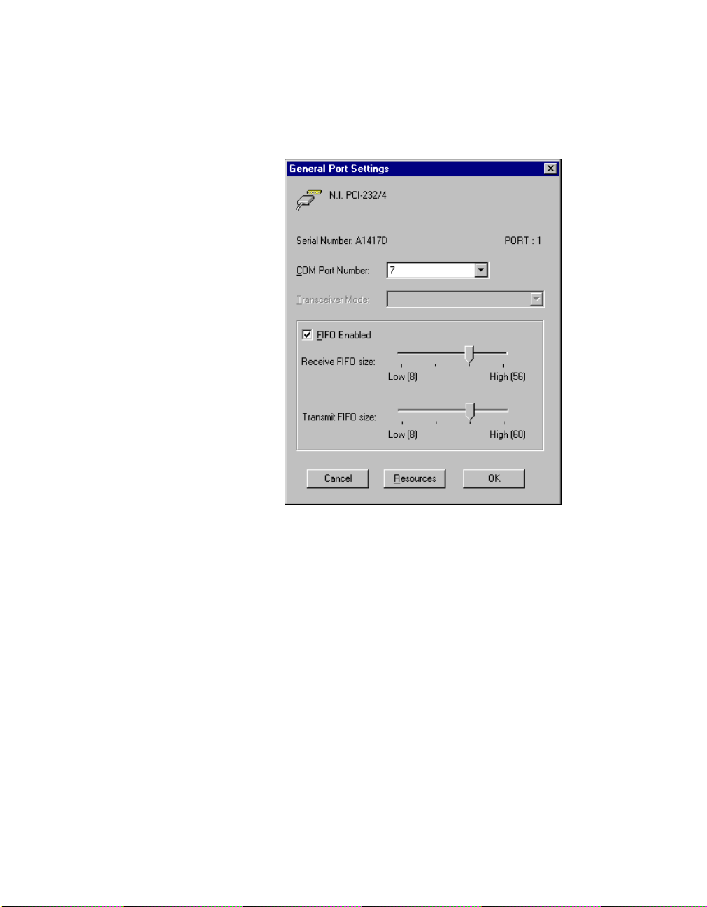
Chapter 2 PCI Serial Hardware Installation, Verification, and Configuration
General Port Settings
The following sections describe the options you can set in the General
Port Settings dialog box, shown in Figure 2-11.
Figure 2-11. General Port Settings Dialog Box
COM Port Number
You can use the COM Port Number control to change the logical COMx
name of the selected port.
Transceiver Mode
The Transceiver Mode list box shows the transceiver mode in use, and
applies only to PCI-485 boards. For more information about transceiver
modes, refer to Chapter 6, Using Your Serial Hardware.
FIFO Enabled
You can use the FIFO Enabled checkbox to enable or disable the
FIFO buffers on the selected port. FIFO buffers are present on the
16550-compatible UARTs—one for the transmitter and one for the
receiver.
Serial Hardware and Software for Windows 2-22 ni.com
Page 46

Chapter 2 PCI Serial Hardware Installation, Verification, and Configuration
FIFO Buffer Size
The Receive FIFO size control sets the number of characters received in
the FIFO before the PC is interrupted to read the data. The Transmit FIFO
size control sets the maximum number of bytes written to the FIFO in a
block when the PC is interrupted to write the data. When you configure
FIFO settings, consider the following points:
• You can select larger FIFO buffer sizes to reduce the number of
interrupts your PC receives and therefore minimize system overhead.
• If transfer rates are high, you can lower the Receive FIFO size value
to prevent overrun errors due to interrupt latency.
• If your data transfer sizes are small and your Receive FIFO size value
is above your data sizes, your system is less efficient. Therefore, set the
Receive FIFO size value below your data sizes.
Resources
To view the resource configuration dialog box for the selected port, click
on the Resources button. You cannot change these resources; they are
automatically assigned.
© National Instruments Corporation 2-23 Serial Hardware and Software for Windows
Page 47

PXI Serial Hardware Installation,
Verification, and Configuration
This chapter describes how to install the NI-Serial software and PXI serial
hardware and how to verify the installation. It also describes how to view
or change the communication port settings.
To begin your installation, see the section of this chapter containing
instructions for your operating system (Windows 2000, Windows Me/9x,or
Windows NT.)
Windows 2000
Install the Software
Before you install your serial hardware, complete the following steps to
install the NI-Serial software for Windows 2000:
1. Select Start»Settings»Control Panel.
2. Double-click on the Add/Remove Programs icon. The Add/Remove
Programs dialog box appears.
3. ClickontheAdd New Programs button and then the CD or Floppy
button.
4. When prompted, insert the NI-Serial Software for Windows
2000/NT/Me/9x CD and click on the Next button.
5. When prompted, click on the Finish button to install the program files
from the CD.
6. The setup wizard begins. The setup wizard guides you through the
necessary steps to install the NI-Serial software. To exit the setup
wizard at any time, click on the Cancel button.
7. If you need to install your hardware, or if this is your first time to install
the NI-Serial software for Windows 2000, skip to the next section,
Install the Hardware. Otherwise, continue to step 8.
8. If your hardware is already installed, restart Windows 2000.
3
© National Instruments Corporation 3-1 Serial Hardware and Software for Windows
Page 48

Chapter 3 PXI Serial Hardware Installation, Verification, and Configuration
9. Windows 2000 should automatically detect your hardware and display
the Found New Hardware Wizard. Complete the wizard by clicking
Next in each window and then Finish. When you complete the wizard,
continue to the Verify the Installation section.
If the Found New Hardware Wizard does not appear, refer to the
Forcing Windows to Detect Your Hardware section in Appendix D,
Troubleshooting and Common Questions.
Install the Hardware
Caution
Before you remove your board from the package, touch the antistatic plastic
package to a metal part of your system chassis to discharge electrostatic energy, which can
damage several components on your serial board.
To install your PXI serial board, complete the following steps:
1. Turn off your PXI or CompactPCI chassis. Keep the chassis plugged
in so that it remains grounded while you install the PXI serial board.
2. Find an unused PXI or CompactPCI 5 V peripheral slot.
3. Remove the corresponding filler panel.
4. Touch a metal part on your chassis to discharge any static electricity.
5. Insert the PXI serial board into the 5 V slot. Use the injector/ejector
handle to fully inject the device into place. Figure 3-1 shows how
to install the PXI serial board into a PXI or CompactPCI chassis.
Serial Hardware and Software for Windows 3-2 ni.com
Page 49

Chapter 3 PXI Serial Hardware Installation, Verification, and Configuration
3
ON
STANDBY
1
2
3
4
5
6
7
2
8
4
1
1 Injector/Ejector Handle (In Down
Position)
3 PXI Chassis
4 Injector/Ejector Rail
2 PXI Serial Board
Figure 3-1. Installing the PXI Serial Board
6. Screw the PXI serial board front panel to the front panel mounting rail
of the PXI or CompactPCI chassis.
7. Turn on your PXI or CompactPCI chassis and start Windows 2000.
8. Windows 2000 should automatically detect your hardware and display
the Found New Hardware Wizard. Complete the wizard by clicking
Next in each window and then Finish.
If the Found New Hardware Wizard does not appear, refer to the
Forcing Windows to Detect Your Hardware section in Appendix D,
Troubleshooting and Common Questions.
The serial hardware installation is complete. Continue to the next section,
Verify the Installation.
© National Instruments Corporation 3-3 Serial Hardware and Software for Windows
Page 50

Chapter 3 PXI Serial Hardware Installation, Verification, and Configuration
Verify the Installation
To verify the hardware and software installation, complete the following
steps:
1. Select Start»Settings»Control Panel and double-click on the
System icon.
2. Click on the Hardware tabandclickontheDevice Manager button.
3. Double-click on the Ports (COM & LPT) icon to display all of
the ports.
4. Double-click on the Multi-function adapters icon.
The PXI serial boards are configured as devices belonging to the
multi-function adapters class. The multi-function parent device is
listed under the Multi-function adapters icon, and each child device
is listed as a port under the Ports (COM & LPT) icon.
Figure 3-2 shows the Device Manager tab for serial hardware that is
installed properly.
Figure 3-2. Device Manager for PXI Serial Board Ports
Serial Hardware and Software for Windows 3-4 ni.com
Page 51

Chapter 3 PXI Serial Hardware Installation, Verification, and Configuration
5. Verify the hardware resources, as follows:
a. In the Device Manager under Multi-function adapters,
double-click on a serial board.
b. ClickontheResources tab. If the resources were assigned
properly, the Resources tab shows which resources are assigned
to your serial ports.
c. Repeat steps 5a and 5b until you have verified the resources for
each board.
6. (Optional) To determine which physical port is associated with COMx,
note the Port 1, Port 2, etc. entries next to the COM numbers. For all
serial hardware, PORT1 refers to the top port, PORT2 refers to the next
port down, and so on.
7. Run the diagnostic utility, as follows: select Start»Programs»
National Instruments»NI-Serial»Diagnostics.
The diagnostic utility verifies that your serial driver is installed
properly, that the configuration of your hardware does not conflict with
anything else in your system, and that the serial driver can
communicate with your hardware correctly.
If the test is successful, your serial hardware and software are installed
properly. If the test fails, refer to Appendix D, Troubleshooting and
Common Questions, to troubleshoot the problem.
8. After you verify the hardware and software installation, connect the
cables. See Appendix A, Connector Descriptions, for information
about cable connections.
Configure Communication Port Settings
The serial configuration utility is fully integrated into the Windows 2000
Device Manager. You can use it to view or change the configuration of
your serial ports.
To configure a serial port, complete the following steps:
1. Select Start»Settings»Control Panel and double-click on the
System icon.
2. ClickontheHardware tabandclickontheDevice Manager button.
3. Double-click on the Ports (COM & LPT) icon.
© National Instruments Corporation 3-5 Serial Hardware and Software for Windows
Page 52

Chapter 3 PXI Serial Hardware Installation, Verification, and Configuration
4. Double-click on the port you want to configure and refer to the
following instructions:
• To view the hardware resources assigned to the serial port, click
on the Resources tab.
• To view or change the port settings, click on the Port Settings tab.
For more information about the settings, refer to the next section,
Port Settings Tab.
• To change the RS-485 transceiver mode, or to enable or disable
the FIFOs on the serial hardware, in the Port Settings tab, click
on the Advanced button. For more information about the settings,
refer to the next section, Port Settings Tab.
Note
Transceiver modes apply to RS-485 interfaces only. For more information about
transceiver modes, refer to Chapter 6, Using Your Serial Hardware.
5. To save your changes, click on the OK button. To exit without saving
the changes, click on the Cancel button.
Port Settings Tab
In the Port Settings tab, you can change any of the settings by clicking on
the arrow button to the right of a field. When you click on the arrow button,
a list of valid values for that field appears and you can select the desired
setting from the list. Figure 3-3 shows the Port Settings tab.
Serial Hardware and Software for Windows 3-6 ni.com
Page 53

Chapter 3 PXI Serial Hardware Installation, Verification, and Configuration
Figure 3-3. Port Settings Tab
Advanced Settings
To view or change the advanced settings, click on the Advanced button.
Figure 3-4 shows the Advanced Settings dialog box.
© National Instruments Corporation 3-7 Serial Hardware and Software for Windows
Page 54

Chapter 3 PXI Serial Hardware Installation, Verification, and Configuration
Figure 3-4. Advanced Settings Dialog Box
The following sections describe the advanced settings options.
Transceiver Mode
This field shows the transceiver mode in use, and applies only to RS-485
boards. For more information about transceiver modes, refer to Chapter 6,
Using Your Serial Hardware.
Use FIFO Buffers
FIFO buffers are present on the 16550-compatible UARTs—one for the
transmitter and one for the receiver. The Receive Buffer control sets the
number of characters received in the FIFO before the PC is interrupted to
read the data. The Transmit Buffer control sets the maximum number of
bytes written to the FIFO in a block when the PC is interrupted to write the
data. When you configure FIFO settings, consider the following points:
• You can select larger FIFO buffer sizes to reduce the number of
interrupts your PC receives and therefore minimize system overhead.
• If transfer rates are high, you can lower the Receive Buffer value to
prevent overrun errors due to interrupt latency.
• If your data transfer sizes are small and your Receive Buffer value is
above your data sizes, your system is less efficient. Therefore, set the
Receive Buffer value below your data sizes.
Serial Hardware and Software for Windows 3-8 ni.com
Page 55

Restore Defaults
To reset the fields to their default values at any time, click on the Restore
Defaults button.
Windows Me/9x
Install the Software
Before you install your serial hardware, complete the following steps to
install the NI-Serial software for Windows Me/9x:
1. Select Start»Settings»Control Panel.
2. Double-click on the Add/Remove Programs icon. The Add/Remove
3. ClickontheInstall button.
4. When prompted, insert the NI-Serial Software for Windows
5. If you need to install your hardware, or if this is your first time to install
6. If your hardware is already installed, restart Windows Me/9x.
Chapter 3 PXI Serial Hardware Installation, Verification, and Configuration
Programs dialog box appears.
2000/NT/Me/9x CD and click on the Next button. The setup wizard
begins. The setup wizard guides you through the necessary steps to
install the NI-Serial software. To go back and change values where
appropriate, click on the Back button. To exit the setup wizard at any
time, click on the Cancel button.
the NI-Serial software for Windows Me/9x, skip to the next section,
Install the Hardware. Otherwise, continue to step 6.
Windows Me/9x should automatically detect your hardware and
display one or more New Hardware Found dialog boxes. Make sure
that Windows Default Driver is selected and click on the OK button.
When you finish, continue to the Verify the Installation section.
If no New Hardware Found dialog box appears, refer to the Forcing
Windows to Detect Your Hardware sectioninAppendixD,
Troubleshooting and Common Questions.
© National Instruments Corporation 3-9 Serial Hardware and Software for Windows
Page 56

Chapter 3 PXI Serial Hardware Installation, Verification, and Configuration
Install the Hardware
Caution
Before you remove your board from the package, touch the antistatic plastic
package to a metal part of your system chassis to discharge electrostatic energy, which can
damage several components on your serial board.
To install your PXI serial board, complete the following steps:
1. Turn off your PXI or CompactPCI chassis. Keep the chassis plugged
in so that it remains grounded while you install the PXI serial board.
2. Find an unused PXI or CompactPCI 5 V peripheral slot.
3. Remove the corresponding filler panel.
4. Touch a metal part on your chassis to discharge any static electricity.
5. Insert the PXI serial board into the 5 V slot. Use the injector/ejector
handle to fully inject the device into place. Figure 3-5 shows how
to install the PXI serial board into a PXI or CompactPCI chassis.
3
ON
STANDBY
1
2
3
4
5
6
7
2
8
4
1
1 Injector/Ejector Handle (In Down
Position)
3 PXI Chassis
4 Injector/Ejector Rail
2 PXI Serial Board
Figure 3-5. Installing the PXI Serial Board
Serial Hardware and Software for Windows 3-10 ni.com
Page 57

6. Screw the PXI serial board front panel to the front panel mounting rail
7. Turn on your PXI or CompactPCI chassis and start Windows Me/9x.
8. Windows Me/9x should automatically detect your hardware and
The serial hardware installation is complete. Continue to the next section,
Verify the Installation.
Verify the Installation
Before you verify the installation, keep in mind that the serial ports
built into your computer are typically named from COM1 to COM4.
Windows Me/9x typically issues port names to the ports on NI serial
hardware starting with COM5, COM6, and so on. If not enough resources
are available to assign to all the NI serial ports, the port with the higher
COMx name is not configured.
Chapter 3 PXI Serial Hardware Installation, Verification, and Configuration
of the PXI or CompactPCI chassis.
display one or more New Hardware Found dialog boxes. Make sure
that Windows Default Driver is selected and click on the OK button.
If no New Hardware Found dialog box appears, refer to the Forcing
Windows to Detect Your Hardware sectioninAppendixD,
Troubleshooting and Common Questions.
To verify the hardware and software installation, complete the following
steps:
1. Select Start»Settings»Control Panel and double-click on the
System icon.
2. ClickontheDevice Manager tabandclickontheView devices by
type button.
3. Double-click on the Ports (COM & LPT) icon to display all of
the ports.
4. Double-click on the Multi-function adapters icon.
The PXI serial boards are configured as devices belonging to the
multi-function adapters class. The multi-function parent device is
listed under the Multi-function adapters icon, and each child device
is listed as a port under the Ports (COM & LPT) icon.
© National Instruments Corporation 3-11 Serial Hardware and Software for Windows
Page 58

Chapter 3 PXI Serial Hardware Installation, Verification, and Configuration
Figure 3-6 shows the Device Manager tab for serial hardware that is
installed properly.
Figure 3-6. Device Manager for PXI Serial Board Ports
5. Verify the hardware resources, as follows:
a. In the Device Manager tab, under Multi-function adapters,
double-click on a serial board.
b. ClickontheResources tab. If the resources were assigned
properly, the Resources tab shows which resources are assigned
to your serial ports.
c. Repeat steps 5a and 5b until you have verified the resources for
each board.
Serial Hardware and Software for Windows 3-12 ni.com
Page 59

Chapter 3 PXI Serial Hardware Installation, Verification, and Configuration
6. (Optional) To determine which physical port is associated with COMx,
complete the following steps:
a. In the Device Manager tab, under Ports (COM & LPT),
double-click on the serial port (COMx).
b. Click on the Port Settings tab to display the serial number of the
serial hardware and the physical port number starting at 1. For all
serial hardware, PORT1 refers to the top port, PORT2 refers to the
next port down, and so on.
7. Run the diagnostic utility, as follows: select
Start»Programs»National Instruments Serial»diagnostics.
The diagnostic utility verifies that your serial driver is installed
properly, that the configuration of your hardware does not conflict with
anything else in your system, and that the serial driver can
communicate with your hardware correctly.
If the test is successful, your serial hardware and software are installed
properly. If the test fails, refer to Appendix D, Troubleshooting and
Common Questions, to troubleshoot the problem.
8. After you verify the hardware and software installation, connect the
cables. See Appendix A, Connector Descriptions, for information
about cable connections.
Configure Communication Port Settings
The serial configuration utility is fully integrated into the Windows Me/9x
Device Manager. You can use it to view or change the configuration of
your serial ports.
To configure a serial port, complete the following steps:
1. Select Start»Settings»Control Panel and double-click on the
System icon.
2. ClickontheDevice Manager tabandclickontheView devices by
type button.
3. Double-click on the Ports (COM & LPT) icon.
Note
If you want your serial ports to use the names COM1, COM2, COM3, or COM4,
refer to the Common Questions section of Appendix D, Troubleshooting and
Common Questions.
© National Instruments Corporation 3-13 Serial Hardware and Software for Windows
Page 60

Chapter 3 PXI Serial Hardware Installation, Verification, and Configuration
4. Double-click on the port you want to configure and refer to the
following instructions:
• To view the hardware resources assigned to the serial port, click
on the Resources tab.
• To view or change the port settings, click on the Port Settings tab.
For more information about the settings, refer to the next section,
Port Settings Tab.
• To change the RS-485 transceiver mode, or to enable or disable
the FIFOs on the serial hardware, in the Port Settings tab, click
on the Advanced button. For more information about the settings,
refer to the next section, Port Settings Tab.
Note
Transceiver modes apply to RS-485 interfaces only. For more information about
transceiver modes, refer to Chapter 6, Using Your Serial Hardware.
5. To save your changes, click on the OK button. To exit without saving
the changes, click on the Cancel button.
Serial Hardware and Software for Windows 3-14 ni.com
Page 61

Chapter 3 PXI Serial Hardware Installation, Verification, and Configuration
Port Settings Tab
In the Port Settings tab, you can change any of the settings by clicking on
the arrow button to the right of a field. When you click on the arrow button,
a list of valid values for that field appears and you can select the desired
setting from the list. Figure 3-7 shows the Port Settings tab.
Figure 3-7. Port Settings Tab
© National Instruments Corporation 3-15 Serial Hardware and Software for Windows
Page 62

Chapter 3 PXI Serial Hardware Installation, Verification, and Configuration
Advanced Port Settings
To view or change the advanced port settings, click on the Advanced
button. Figure 3-8 shows the Advanced Port Settings dialog box.
Figure 3-8. Advanced Settings Dialog Box
The following sections describe the advanced settings options.
Transceiver Mode
This field shows the transceiver mode in use, and applies only to RS-485
boards. For more information about transceiver modes, refer to Chapter 6,
Using Your Serial Hardware.
Use FIFO Buffers
FIFO buffers are present on the 16550-compatible UARTs—one for the
transmitter and one for the receiver. The Receive Buffer control sets the
number of characters received in the FIFO before the PC is interrupted to
read the data. The Transmit Buffer control sets the maximum number of
bytes written to the FIFO in a block when the PC is interrupted to write the
data. When you configure FIFO settings, consider the following points:
• You can select larger FIFO buffer sizes to reduce the number of
interrupts your PC receives and therefore minimize system overhead.
• If transfer rates are high, you can lower the Receive Buffer value to
prevent overrun errors due to interrupt latency.
• If your data transfer sizes are small and your Receive Buffer value is
above your data sizes, your system is less efficient. Therefore, set the
Receive Buffer value below your data sizes.
Serial Hardware and Software for Windows 3-16 ni.com
Page 63

Windows NT
Install the Software
Chapter 3 PXI Serial Hardware Installation, Verification, and Configuration
Restore Defaults
To reset the fields to their default values at any time, click on the Restore
Defaults button.
Before you install your serial hardware, complete the following steps to
install the NI-Serial software for Windows NT:
1. Loginas
privileges.
2. Select Start»Settings»Control Panel.
3. Double-click on the Add/Remove Programs icon. The Add/Remove
Programs dialog box appears.
4. ClickontheInstall button.
5. When prompted, insert the NI-Serial Software for Windows
2000/NT/Me/9x, and click on the Next button. The setup wizard
begins. The setup wizard guides you through the necessary steps to
install the NI-Serial software. To go back and change values where
appropriate, click on the Back button. To exit the setup wizard at any
time, click on the Cancel button.
Administrator
or as a user who has
Administrator
Note
The setup wizard backs up the Windows NT serial driver
serial.bak
the
WinNT\system32\drivers
andthenoverwrites
6. If you your hardware is already installed, restart Windows NT and
continue to the Verify the Installation section.
The software installation is complete. Continue to the next section, Install
the Hardware.
serial.sys
directory.
. You can find
serial.sys
serial.sys
to
in
Install the Hardware
Caution
package to a metal part of your system chassis to discharge electrostatic energy, which can
damage several components on your serial board.
© National Instruments Corporation 3-17 Serial Hardware and Software for Windows
Before you remove your board from the package, touch the antistatic plastic
Page 64

Chapter 3 PXI Serial Hardware Installation, Verification, and Configuration
To install your PXI serial board, complete the following steps:
1. Turn off your PXI or CompactPCI chassis. Keep the PXI or
CompactPCI chassis plugged in so that it remains grounded while you
install the PXI serial board.
2. Find an unused PXI or CompactPCI 5 V peripheral slot.
3. Remove the corresponding filler panel.
4. Touch a metal part on your chassis to discharge any static electricity.
5. Insert the PXI serial board into the 5 V slot. Use the injector/ejector
handle to fully inject the device into place. Figure 3-9 shows how to
install the PXI serial board into a PXI or CompactPCI chassis.
3
ON
STANDBY
1
2
3
4
5
6
7
2
8
4
1
1 Injector/Ejector Handle (In Down
Position)
3 PXI Chassis
4 Injector/Ejector Rail
2 PXI Serial Board
Figure 3-9. Installing the PXI Serial Board
Serial Hardware and Software for Windows 3-18 ni.com
Page 65

6. Screw the PXI serial board front panel to the front panel mounting rail
7. Turn on your PXI or CompactPCI chassis and start Windows NT.
The serial hardware installation is complete. Continue to the next section,
Verify the Installation.
Verify the Installation
To verify the hardware and software installation, complete the following
steps:
1. Determine which physical port is associated with COMx, as follows:
2. Run the diagnostic utility, as follows: select
3. After you verify the hardware and software installation, connect the
Chapter 3 PXI Serial Hardware Installation, Verification, and Configuration
of the PXI or CompactPCI chassis.
a. Select Start»Settings»Control Panel and double-click on the
niports icon.
A list of installed National Instruments ports with their logical
COMx names appears. If your interface is not on this list, refer to
Appendix D, Troubleshooting and Common Questions.
b. Select the COM port that you want to verify and click on the
Settings button.
The General Port Settings dialog box displays the serial number
of the serial hardware and the physical port number starting at 1.
For all serial hardware, PORT1 refers to the top port, PORT2
refers to the next port down, and so on.
Start»Programs»National Instruments Serial»diagnostics.
The diagnostic utility verifies that your serial driver is installed
properly, that the configuration of your hardware does not conflict with
anything else in your system, and that the serial driver can
communicate with your hardware correctly.
If the test is successful, your serial hardware and software are installed
properly. If the test fails, refer to Appendix D, Troubleshooting and
Common Questions, to troubleshoot the problem.
cables. See Appendix A, Connector Descriptions, for information
about cable connections.
© National Instruments Corporation 3-19 Serial Hardware and Software for Windows
Page 66

Chapter 3 PXI Serial Hardware Installation, Verification, and Configuration
Configure Communication Port Settings
The serial configuration utility is fully integrated into the Windows NT
Control Panel. You can use it to view or change the configuration of your
serial ports.
To configure a serial port, complete the following steps:
1. Select Start»Settings»Control Panel and double-click on the niports
icon. A list of installed National Instruments ports appears, as shown
in Figure 3-10.
Figure 3-10. niports Configuration Utility
2. Select the port that you want to configure and refer to the following
instructions:
• To remove hardware information about the port from
WindowsNT,clickontheDelete button. You should do this
before you remove your hardware.
• To view or change the port settings, click on the Settings button.
For more information about the settings, refer to the next section,
General Port Settings.
• In the General Port Settings dialog box, click on the Resources
button to view the resources for the port.
Serial Hardware and Software for Windows 3-20 ni.com
Page 67

Chapter 3 PXI Serial Hardware Installation, Verification, and Configuration
General Port Settings
The following sections describe the options you can set in the General
Port Settings dialog box, shown in Figure 3-11.
Figure 3-11. General Port Settings Dialog Box
COM Port Number
You can use the COM Port Number control to change the logical COMx
name of the selected port.
Transceiver Mode
The Transceiver Mode list box shows the transceiver mode in use, and
applies only to RS-485 boards. For more information about transceiver
modes, refer to Chapter 6, Using Your Serial Hardware.
FIFO Enabled
You can use the FIFO Enabled checkbox to enable or disable the
FIFO buffers on the selected port. FIFO buffers are present on the
16550-compatible UARTs—one for the transmitter and one for the
receiver.
© National Instruments Corporation 3-21 Serial Hardware and Software for Windows
Page 68

Chapter 3 PXI Serial Hardware Installation, Verification, and Configuration
FIFO Buffer Size
The Receive FIFO size control sets the number of characters received in
the FIFO before the PC is interrupted to read the data. The Transmit FIFO
size control sets the maximum number of bytes written to the FIFO in a
block when the PC is interrupted to write the data. When you configure
FIFO settings, consider the following points:
• You can select larger FIFO buffer sizes to reduce the number of
interrupts your PC receives and therefore minimize system overhead.
• If transfer rates are high, you can lower the Receive FIFO size value
to prevent overrun errors due to interrupt latency.
• If your data transfer sizes are small and your Receive FIFO size value
is above your data sizes, your system is less efficient. Therefore, set the
Receive FIFO size value below your data sizes.
Resources
To view the resource configuration dialog box for the selected port, click
on the Resources button. You cannot change these resources; they are
automatically assigned.
Serial Hardware and Software for Windows 3-22 ni.com
Page 69

PCMCIA Serial Hardware
Installation, Verification, and
Configuration
This chapter describes how to install the NI-Serial software and PCMCIA
serial hardware and how to verify the installation. It also describes how to
view or change the communication port settings.
To begin your installation, see the section of this chapter containing
instructions for your operating system (Windows 2000, Windows Me/9x,or
Windows NT.)
Windows 2000
Install the Software
Before you install your serial hardware, complete the following steps to
install the NI-Serial software for Windows 2000:
1. Select Start»Settings»Control Panel.
2. Double-click on the Add/Remove Programs icon. The Add/Remove
Programs dialog box appears.
3. ClickontheAdd New Programs button and then the CD or Floppy
button.
4. When prompted, insert the NI-Serial Software for Windows
2000/NT/Me/9x CD and click on the Next button.
5. When prompted, click on the Finish button to install the program files
from the CD.
6. The setup wizard begins. The setup wizard guides you through the
necessary steps to install the NI-Serial software. To exit the setup
wizard at any time, click on the Cancel button.
7. If you need to install your hardware, or if this is your first time to install
the NI-Serial software for Windows 2000, skip to the next section,
Install the Hardware. Otherwise, continue to step 8.
4
© National Instruments Corporation 4-1 Serial Hardware and Software for Windows
Page 70

Chapter 4 PCMCIA Serial Hardware Installation, Verification, and Configuration
8. Windows 2000 should automatically detect your hardware and display
the Found New Hardware Wizard. Complete the wizard by clicking
Next in each window and then Finish. When you complete the wizard,
continue to the Verify the Installation section.
If the Found New Hardware Wizard does not appear, refer to the
Forcing Windows to Detect Your Hardware section in Appendix D,
Troubleshooting and Common Questions.
Install the Hardware
To install the PCMCIA-232 or PCMCIA-485 in your computer, first start
Windows 2000. If the card is not already inserted, insert it into a free PC
Card (PCMCIA) socket the same way you insert a disk into a floppy drive.
The card has no jumpers or switches to set, and you do not need to shut
down the system before you insert it.
Windows 2000 should automatically detect your hardware and display the
Found New Hardware Wizard. Complete the wizard by clicking Next in
each window and then Finish.
If the Found New Hardware Wizard does not appear, refer to the Forcing
Windows to Detect Your Hardware sectioninAppendixD,
Troubleshooting and Common Questions.
Serial Hardware and Software for Windows 4-2 ni.com
Page 71

Chapter 4 PCMCIA Serial Hardware Installation, Verification, and Configuration
Figure 4-1 shows how to insert a PCMCIA serial card and how to connect
the cable.
1
2
1PCMCIASocket 2 PCMCIA Serial Cable
Figure 4-1.
Inserting a PCMCIA Serial Card
The serial hardware installation is complete. Continue to the next section,
Verify the Installation.
Verify the Installation
To verify the hardware and software installation, complete the following
steps:
1. Select Start»Settings»Control Panel and double-click on the
System icon.
2. ClickontheHardware tabandclickontheDevice Manager button.
3. Double-click on the Ports (COM & LPT) icon to display all of
the ports.
4. Double-click on the Multi-function adapters icon.
The PCMCIA serial cards are configured as devices belonging to the
multi-function adapters class. The multi-function parent device is
listed under the Multi-function adapters icon, and each child device
is listed as a port under the Ports (COM & LPT) icon.
© National Instruments Corporation 4-3 Serial Hardware and Software for Windows
Page 72

Chapter 4 PCMCIA Serial Hardware Installation, Verification, and Configuration
Figure 4-2 shows the Device Manager tab for serial hardware that is
installed properly.
Figure 4-2. Device Manager for PCMCIA Serial Card Ports
5. Verify the hardware resources, as follows:
a. In the Device Manager under Multi-function adapters,
double-click on a serial card.
b. ClickontheResources tab. If the resources were assigned
properly, the Resources tab shows which resources are assigned
to your serial ports.
c. Repeat steps 5a and 5b until you have verified the resources for
each board.
6. (Optional) To determine which physical port is associated with COMx,
note the Port 1, Port 2, etc. entries next to the COM numbers. For all
serial hardware, PORT1 refers to the top port, PORT2 refers to the next
port down, and so on.
Serial Hardware and Software for Windows 4-4 ni.com
Page 73

Chapter 4 PCMCIA Serial Hardware Installation, Verification, and Configuration
7. Run the diagnostic utility, as follows: select Start»Programs»
National Instruments»NI-Serial»Diagnostics.
The diagnostic utility verifies that your serial driver is installed
properly, that the configuration of your hardware does not conflict with
anything else in your system, and that the serial driver can
communicate with your hardware correctly.
If the test is successful, your serial hardware and software are installed
properly. If the test fails, refer to Appendix D, Troubleshooting and
Common Questions, to troubleshoot the problem.
8. After you verify the hardware and software installation, connect the
cables. See Appendix A, Connector Descriptions, for information
about cable connections.
Configure Communication Port Settings
The serial configuration utility is fully integrated into the Windows 2000
Device Manager. You can use it to view or change the configuration of
your serial ports.
To configure a serial port, complete the following steps:
1. Select Start»Settings»Control Panel and double-click on the
System icon.
2. ClickontheHardware tabandclickontheDevice Manager button.
3. Double-click on the Ports (COM & LPT) icon.
4. Double-click on the port you want to configure and refer to the
following instructions:
• To view the hardware resources assigned to the serial port, click
on the Resources tab.
• To view or change the port settings, click on the Port Settings tab.
For more information about the settings, refer to the next section,
Port Settings Tab.
• To change the RS-485 transceiver mode, or to enable or disable
the FIFOs on the serial hardware, in the Port Settings tab, click
on the Advanced button. For more information about the settings,
refer to the next section, Port Settings Tab.
Note
Transceiver modes apply to RS-485 interfaces only. For more information about
transceiver modes, refer to Chapter 6, Using Your Serial Hardware.
5. To save your changes, click on the OK button. To exit without saving
the changes, click on the Cancel button.
© National Instruments Corporation 4-5 Serial Hardware and Software for Windows
Page 74

Chapter 4 PCMCIA Serial Hardware Installation, Verification, and Configuration
Port Settings Tab
In the Port Settings tab, you can change any of the settings by clicking on
the arrow button to the right of a field. When you click on the arrow button,
a list of valid values for that field appears and you can select the desired
setting from the list. Figure 4-3 shows the Port Settings tab.
Figure 4-3. Port Settings Tab
Serial Hardware and Software for Windows 4-6 ni.com
Page 75

Chapter 4 PCMCIA Serial Hardware Installation, Verification, and Configuration
Advanced Settings
To view or change the advanced settings, click on the Advanced button.
Figure 4-4 shows the Advanced Settings dialog box.
Figure 4-4.
The following sections describe the advanced settings options.
Advanced Settings Dialog Box
Transceiver Mode
This field shows the transceiver mode in use, and applies only to
PCMCIA-485 boards. For more information about transceiver modes, refer
to Chapter 6, Using Your Serial Hardware.
© National Instruments Corporation 4-7 Serial Hardware and Software for Windows
Page 76

Chapter 4 PCMCIA Serial Hardware Installation, Verification, and Configuration
Use FIFO Buffers
FIFO buffers are present on the 16550-compatible UARTs—one for the
transmitter and one for the receiver. The Receive Buffer control sets the
number of characters received in the FIFO before the PC is interrupted to
read the data. The Transmit Buffer control sets the maximum number of
bytes written to the FIFO in a block when the PC is interrupted to write the
data. When you configure FIFO settings, consider the following points:
• You can select larger FIFO buffer sizes to reduce the number of
interrupts your PC receives and therefore minimize system overhead.
• If transfer rates are high, you can lower the Receive Buffer value to
prevent overrun errors due to interrupt latency.
• If your data transfer sizes are small and your Receive Buffer value is
above your data sizes, your system is less efficient. Therefore, set the
Receive Buffer value below your data sizes.
Restore Defaults
To reset the fields to their default values at any time, click on the Restore
Defaults button.
Windows Me/9x
Install the Software
Install the NI-Serial software for Windows Me/9x before you install the
hardware:
1. Select Start»Settings»Control Panel.
2. Double-click on the Add/Remove Programs iconin the ControlPanel
to launch the Add/Remove Programs applet. The Add/Remove
Programs dialog box appears.
3. Click on the Install button.
4. When prompted, insert the NI-Serial Software for Windows
2000/NT/Me/9x CD and click on the Next button to proceed.
The software installation wizard begins.
The setup wizard guides you through the necessary steps to install the
NI-Serial software. You can go back and change values where
appropriate by clicking on the Back button. You can exit the setup
where appropriate by clicking on the Cancel button.
Serial Hardware and Software for Windows 4-8 ni.com
Page 77

Install the Hardware
Chapter 4 PCMCIA Serial Hardware Installation, Verification, and Configuration
5. If you need to install your hardware, or if this is your first time to install
the NI-Serial software for Windows Me/9x, skip to the next section,
Install the Hardware. Otherwise, continue to Step 6.
6. If your hardware is already installed, restart Windows Me/9x.
Windows Me/9x should automatically detect your hardware and
display one or more New Hardware Found dialog boxes. When you
finish, continue to the Verify the Installation section.
If no New Hardware Found dialog box appears, refer to the section
Forcing Windows to Detect Your Hardware in Appendix D,
Troubleshooting and Common Questions.
To install the PCMCIA-232 or PCMCIA-485 in your computer, first start
Windows Me/9x. If the card is not already inserted, insert it into a free PC
Card (PCMCIA) socket the same way you insert a disk into a floppy drive.
The card has no jumpers or switches to set, and you do not need to shut
down the system before you insert it.
Windows Me/9x automatically displays one or more New Hardware
Found dialog boxes when it detects and configures a PC Card.
If the New Hardware Found dialog box does not appear, refer to the
Forcing Windows to Detect Your Hardware section in Appendix D,
Troubleshooting and Common Questions.
© National Instruments Corporation 4-9 Serial Hardware and Software for Windows
Page 78

Chapter 4 PCMCIA Serial Hardware Installation, Verification, and Configuration
Figure 4-5 shows how to insert a PCMCIA serial card and how to connect
the cable.
1
2
1PCMCIASocket 2 PCMCIA Serial Cable
Figure 4-5. Inserting a PCMCIA Serial Card
The serial hardware installation is complete. Continue to the next section,
Verify the Installation.
Verify the Installation
When you begin to verify the installation, keep in mind that the serial ports
built into the computer are typically named from COM1 to COM4.
Windows Me/9x typically issues port names to the ports on NI serial
hardware starting with COM5, COM6, and so on. If not enough resources
are available to assign to all the NI serial ports, the port with the higher
COMx name is left unconfigured.
Double-click on the System icon in the Control Panel. In the System
Properties window that appears, select the Device Manager tab, and click
on the View devices by type button at the top of the page. If necessary,
double-click on the Ports (COM & LPT) icon to view all of the ports.
Serial Hardware and Software for Windows 4-10 ni.com
Page 79

Chapter 4 PCMCIA Serial Hardware Installation, Verification, and Configuration
The two-port and four-port PCMCIA cards are configured as devices
belonging to the “multi-function adapters” class. The multi-function parent
device is listed under the Multi-function adapters icon, and each child
device is listed as a port under the Ports (COM & LPT) icon. If you have
installed one of these interfaces, double-click on the Multi-function
adapters icon as well as the Ports (COM & LPT) icon.
If a circled exclamation point appears through the port icon, the serial port
is not installed properly. A problem with the port could have occurred
because Windows Me/9x could not acquire resources for the port, or
because an interrupt request resource conflict exists. If no circled
exclamation point appears, the serial hardware is installed correctly.
Figure 4-6 shows an example of NI serial hardware that is installed
properly.
Figure 4-6.
© National Instruments Corporation 4-11 Serial Hardware and Software for Windows
Device Manager Ports List for PCMCIA Serial Card Correctly Installed
Page 80

Chapter 4 PCMCIA Serial Hardware Installation, Verification, and Configuration
Verify the Hardware Resources
For every port of the newly installed serial interface, double-click on
the name of the serial port in the Device Manager. Then, click on the
Resources tab. If the resources were assigned correctly, the Resources
page shows which resources are assigned to your serial ports.
If Windows Me/9x did not assign any resources to the port, the Resources
page shows only a Set Configuration Manually button. Click on the Set
Configuration Manually button and try to assign conflict-free resources
to your serial hardware. For instructions, refer to the Selecting
Conflict-Free Resources section of Appendix D, Troubleshooting and
Common Questions. You might have to free an interrupt request level so
that one can be assigned to your serial hardware. For instructions, refer to
the section Freeing an Interrupt Request Level in Appendix D,
Troubleshooting and Common Questions.
When you have finished verifying the hardware resources, proceed to the
next section.
Determine Which Physical Port Is Associated
with COMx
For every port of the newly installed serial interface, double-click on the
name of the serial port in the Device Manager. Then, click on the Port
Settings tab. The top of this page displays the serial number of the serial
hardware, and the physical port number starting at 1.
When you have finished verifying the driver installation and physical port,
proceed to the next section.
Run the Diagnostic Test
To verify and test the installation, run the diagnostic program that came
with your NI-Serial software. The diagnostic program verifies that your
serial driver is installed properly, that the configuration of your hardware
does not conflict with anything else in your system, and that the serial
driver can communicate with your hardware correctly.
To run the test, select the diagnostics item under Start»Programs»
National Instruments Serial.
If the diagnostic test completes with no failures, your serial hardware
and software are installed properly. If it fails, refer to Appendix D,
Troubleshooting and Common Questions, for troubleshooting instructions.
Serial Hardware and Software for Windows 4-12 ni.com
Page 81

Chapter 4 PCMCIA Serial Hardware Installation, Verification, and Configuration
After you verify the hardware and software installation, connect the cables.
See Appendix A, Connector Descriptions, for information about cable
connections.
Configure Communication Port Settings
The serial configuration utility is fully integrated with the Windows Me/9x
Device Manager. You can use it to examine or modify the configuration of
the serial port.
Follow these steps to configure the serial port. Repeat the configuration
procedure for each serial port in your system.
1. Select Start»Settings»Control Panel and double-click on the System
icon. The System Properties window appears.
2. Select the Device Manager tab, and click on the View devices by type
button at the top of the page.
3. Double-click on the Ports (COM & LPT) icon.
4. Double-click on the name of the port you want to configure.
You can now view or change information about your serial port in the
following ways:
• ClickontheResources tab to view information about the hardware
resources assigned to the serial port.
• ClickonthePort Settings tab to view information about the software
configuration for the serial port. Refer to the next section, Port Settings
Tab, for more information.
• On the Port Settings tab,clickontheAdvanced button to change the
RS-485 transceiver mode and to enable or disable the FIFOs on the
serial hardware. Refer to the next section, Port Settings Tab,formore
information.
Note
If you use two-wire TXRDY mode, FIFOs must be enabled. Transceiver modes
apply to RS-485 interfaces only. For more information about transceiver modes, refer to
Chapter 6, Using Your Serial Hardware.
After you have selected the serial port parameters for the current port, click
on the OK button to save the changes or click on the Cancel button to exit
the dialog box without saving changes.
© National Instruments Corporation 4-13 Serial Hardware and Software for Windows
Page 82

Chapter 4 PCMCIA Serial Hardware Installation, Verification, and Configuration
Port Settings Tab
On the Port Settings tab, you can change any of the settings by clicking on
the arrow button to the right of the setting. When you click on the arrow
button, a list of valid values for that setting appears. Select the desired
setting from the list. Figure 4-7 shows the Port Settings tab.
Figure 4-7. Port Settings Tab
Serial Hardware and Software for Windows 4-14 ni.com
Page 83

Chapter 4 PCMCIA Serial Hardware Installation, Verification, and Configuration
Advanced Port Settings
You can view or change the advanced port settings by clicking on the
Advanced buttononthePort Settings tab. Figure 4-8 shows the
Advanced Port Settings dialog box.
Figure 4-8.
The following sections describe the advanced settings options.
Advanced Port Settings Dialog Box
Transceiver Mode
This field shows the transceiver mode in use, and applies only to
PCMCIA-485 boards. For more information about transceiver modes,
refer to Chapter 6, Using Your Serial Hardware.
Use FIFO Buffers
FIFO buffers are present on the 16550-compatible UARTs—one for the
transmitter and one for the receiver. The Receive Buffer control sets the
number of characters received in the FIFO before the PC is interrupted to
read the data. The Transmit Buffer control sets the maximum number of
bytes written to the FIFO in a block when the PC is interrupted to write the
data. When you configure FIFO settings, consider the following points:
• You can select larger FIFO buffer sizes to reduce the number of
interrupts your PC receives and therefore minimize system overhead.
• If transfer rates are high, you can lower the Receive Buffer value to
prevent overrun errors due to interrupt latency.
• If your data transfer sizes are small and your Receive Buffer value is
above your data sizes, your system is less efficient. Therefore, set the
Receive Buffer value below your data sizes.
© National Instruments Corporation 4-15 Serial Hardware and Software for Windows
Page 84

Chapter 4 PCMCIA Serial Hardware Installation, Verification, and Configuration
Note
If you want your serial hardware ports to use the names COM1, COM2, COM3, or
COM4, refer to the Common Questions section of Appendix D, Troubleshooting and
Common Questions.
Restore Defaults
To reset the fields to their default values at any time, click on the Restore
Defaults button.
Windows NT
Install the NI-Serial Software
Install the NI-Serial software for Windows NT before you install the
hardware.
1. Logonas
privileges.
2. Select Start»Settings»Control Panel.
3. Double-click on the Add/Remove Programs iconin the ControlPanel
to launch the Add/Remove Programs applet. The Add/Remove
Programs dialog box appears.
Administrator
or as a user who has
Administrator
4. Click on the Install button.
5. When prompted, insert the NI-Serial Software for Windows
2000/NT/Me/9x CD and click on the Next button to proceed.
The software installation wizard begins.
The setup wizard guides you through the necessary steps to install the
NI-Serial software. You can go back and change values where
appropriate by clicking on the Back button. You can exit the setup
where appropriate by clicking on the Cancel button.
Note
This installation backs up the Microsoft Windows NT serial driver
serial.bak
Windows NT
Serial Hardware and Software for Windows 4-16 ni.com
andthenoverwrites
...\system32\drivers
The software installation is complete. Proceed to the next section, Install
the PCMCIA Serial Hardware.
serial.sys
directory.
. You can find
serial.sys
serial.sys
in the
to
Page 85

Chapter 4 PCMCIA Serial Hardware Installation, Verification, and Configuration
Install the PCMCIA Serial Hardware
Complete the following steps to install the PCMCIA-232 or PCMCIA-485
in your computer:
1. Shut down the computer.
2. Insert the card into a free PC Card (PCMCIA) socket the same way you
insert a disk into a floppy drive. The card has no jumpers or switches
to set.
3. Power on the computer and start Windows NT.
Figure 4-9 shows how to insert a PCMCIA serial card and how to connect
the cable.
1
2
1PCMCIASocket 2 PCMCIA Serial Cable
Figure 4-9. Inserting a PCMCIA Serial Card
Proceed to the next section, Select Resources for the PCMCIA Card.
© National Instruments Corporation 4-17 Serial Hardware and Software for Windows
Page 86

Chapter 4 PCMCIA Serial Hardware Installation, Verification, and Configuration
Select Resources for the PCMCIA Card
Complete the following steps to select resources for your PCMCIA card.
1. Select Start»Settings»Control Panel.
2. Double-click on the niports icon.
3. Select the PCMCIA card you just installed from the Add a New
PCMCIA Card list,andclickontheAdd button.
4. In the Resource Configuration dialog box, select nonconflicting base
I/O address and IRQ settings for your port/card, and click on OK.
For more information on selecting resources for your port/card, refer
to the Resource Settings section.
5. Exit niports and restart the computer.
After you have selected resources for your PCMCIA card, proceed to the
next section, Verify the Installation.
Verify the Installation
Determine Which Physical Port Is Associated
with COMx
Select Start»Settings»Control Panel, and double-click on niports.Alist
showing installed National Instruments ports with their logical COMx
names appears. If your interface is not on the list, refer to Appendix D,
Troubleshooting and Common Questions.
Select the COM port you want and click on the Settings button to display
the General Port Settings dialog box for that port. This dialog box
displays the physical port number starting at 1.
When you have finished verifying the driver installation and physical port,
proceed to the next section, Run the Diagnostic Test.
Run the Diagnostic Test
To verify and test the installation, run the diagnostic program that came
with your NI-Serial software. The diagnostic program verifies that your
serial driver is installed properly, that the configuration of your hardware
does not conflict with anything else in your system, and that the serial
driver can communicate with your hardware correctly.
To run the test, select the diagnostics item under Start»Programs»
National Instruments Serial.
Serial Hardware and Software for Windows 4-18 ni.com
Page 87

Chapter 4 PCMCIA Serial Hardware Installation, Verification, and Configuration
If the diagnostic test completes with no failures, your serial hardware and
software are installed properly. If it fails, refer to Appendix D,
Troubleshooting and Common Questions, for troubleshooting instructions.
After you verify the hardware and software installation, connect the cables.
See Appendix A, Connector Descriptions, for information about cable
connections.
Configure Communication Port Settings
The serial configuration utility is fully integrated with the Windows NT
Control Panel. You can use it to examine or modify the configuration of the
serial port.
Follow these steps to configure the serial port.
1. Select Start»Settings»Control Panel and double-click on the niports
icon. A list of National Instruments ports appears, as shown in
Figure 4-10.
Figure 4-10. niports Configuration Utility
2. Select the port you are interested in.
3. ClickontheSettings button to view or configure the port settings.
Refer to the next section, GeneralPortSettings, for more information.
4. ClickontheResources button in the General Port Settings dialog
box to view or configure the resources for the port. Refer to the
Resource Settings section, for more information.
© National Instruments Corporation 4-19 Serial Hardware and Software for Windows
Page 88

Chapter 4 PCMCIA Serial Hardware Installation, Verification, and Configuration
5. Click on Delete to remove hardware information about the port from
Windows NT. You should do this before you physically remove your
PCMCIA card.
6. Click on Add to configure resources for a new PCMCIA card.
General Port Settings
This section describes the options you can set in the General Port Settings
dialog box, shown in Figure 4-11.
Figure 4-11. General Port Settings Dialog Box
COM Port Number
You can use the COM Port Number control to change the COMx name of
the port selected.
Transceiver Mode
The transceiver mode selection shows the transceiver mode in use, and
applies only to PCMCIA-485 cards. Refer to Chapter 6, Using Your Serial
Hardware, for more information about transceiver modes. If you use
two-wire TXRDY
Serial Hardware and Software for Windows 4-20 ni.com
mode, FIFOs must be enabled.
Page 89

Chapter 4 PCMCIA Serial Hardware Installation, Verification, and Configuration
FIFO Enabled
You can use the FIFO Enabled control to enable or disable the FIFO
buffers on the serial port. FIFO buffers are present on the
16550-compatible UARTs—one for the transmitter and one for the
receiver.
FIFO Buffers
The FIFO buffer control is available by clicking on the Advanced button
on the Port Settings tab. FIFO buffers are present on the 16550-compatible
UARTs—one for the transmitter and one for the receiver. The receive FIFO
trigger denotes the number of characters received in the FIFO before the PC
is interrupted to read the data. The transmit FIFO trigger denotes the
maximum number of bytes written to the FIFO in a block when the PC is
interrupted to write the data. Consider the following points when selecting
FIFO settings:
• You can select larger FIFO settings to reduce the number of interrupts
and therefore minimize system overhead.
• If transfer rates are high, you can lower receive FIFO settings to reduce
the number of interrupts and therefore prevent overrun errors due to
interrupt latency.
• If data transfer sizes are small, selecting receive FIFO settings just
above data sizes can reduce efficiency, so select lower settings.
Resources
ClickontheResources button to display the resource configuration dialog
box for the port. For more information on resource configuration, refer to
the next section, Resource Settings.
© National Instruments Corporation 4-21 Serial Hardware and Software for Windows
Page 90

Chapter 4 PCMCIA Serial Hardware Installation, Verification, and Configuration
Resource Settings
The following sections explain the resource configuration options for each
serial interface.
PCMCIA-232, PCMCIA-485, PCMCIA-232/4
Figure 4-12 shows the resource configuration dialog box for a
PCMCIA-485. The PCMCIA-232 and PCMCIA-232/4 dialog boxes
are similar.
Figure 4-12. Resource Configuration Dialog Box for the PCMCIA-485
Base I/O Address: The base I/O address assigned to the port.
IRQ: The IRQ assigned to the port.
Length: The size (in bytes) of the I/O window.
For the PCMCIA-232 and PCMCIA-485, the
length is 8 (the size of the I/O window for one
port).
For the PCMCIA-232/4, the length is 32 bytes
(the size of the I/O window for four ports).
Serial Hardware and Software for Windows 4-22 ni.com
Page 91
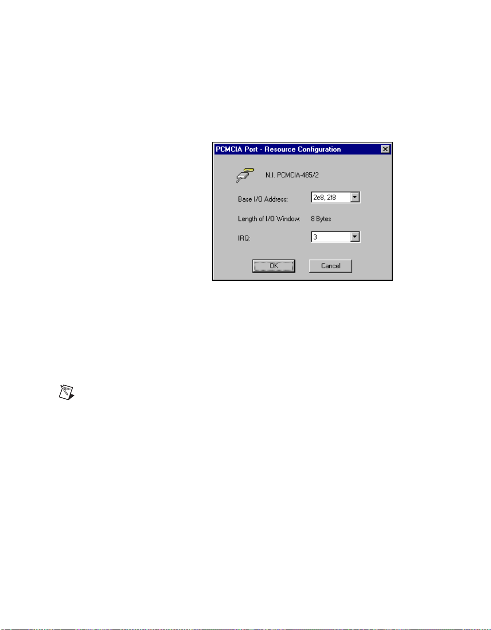
Chapter 4 PCMCIA Serial Hardware Installation, Verification, and Configuration
PCMCIA-232/2, PCMCIA-485/2
These cards require two base I/O settings, one for each port, and they share
an IRQ.
Figure 4-13 shows the resource configuration dialog box for a
PCMCIA-485/2. The PCMCIA-232/2 dialog box is similar.
Figure 4-13. Resource Configuration Dialog Box for the PCMCIA-485/2
Base I/O Address: The base I/O addresses assigned to the two
ports.
IRQ: The IRQ shared by the two ports.
Length: The size of each I/O window (in bytes).
Note
When you select resources for the PCMCIA cards, use the Microsoft Windows NT
diagnostics utility to make sure that the resources have not been assigned to any other
device. This utility displays a list of I/O port addresses and IRQ levels that are currently
being used in your system.
© National Instruments Corporation 4-23 Serial Hardware and Software for Windows
Page 92

AT Serial Hardware Installation,
Verification, and Configuration
This chapter describes how to install the NI-Serial software and AT serial
hardware and how to verify the installation. It also describes how to view
or change the communication port settings.
To begin your installation, see the section of this chapter containing
instructions for your operating system (Windows 2000, Windows Me/9x,or
Windows NT.)
Windows 2000
Install the Software
Before you install your serial hardware, complete the following steps to
install the NI-Serial software for Windows 2000:
1. Select Start»Settings»Control Panel.
2. Double-click on the Add/Remove Programs icon. The Add/Remove
Programs appears.
3. ClickontheAdd New Programs button and then the CD or Floppy
button.
4. When prompted, insert the NI-Serial Software for Windows
2000/NT/Me/9x CD and click on the Next button.
5. When prompted, click on the Finish button to install the program files
from the CD.
6. The setup wizard begins. The setup wizard guides you through the
necessary steps to install the NI-Serial software. To exit the setup
wizard at any time, click on the Cancel button.
7. If you need to install your hardware, or if this is your first time to install
the NI-Serial software for Windows 2000, skip to the next section,
Install the Hardware. Otherwise, continue to step 8.
8. If your hardware is already installed, restart Windows 2000.
5
© National Instruments Corporation 5-1 Serial Hardware and Software for Windows
Page 93

Chapter 5 AT Serial Hardware Installation, Verification, and Configuration
9. Windows 2000 should automatically detect your hardware and display
the Found New Hardware Wizard. Complete the wizard by clicking
Next in each window and then Finish. When you complete the wizard,
continue to the Verify the Installation section.
If the Found New Hardware Wizard does not appear, refer to the
Forcing Windows to Detect Your Hardware section in Appendix D,
Troubleshooting and Common Questions.
Install the Hardware
Note
If you are installing a AT-485, you might need to adjust the value of the bias resistors,
depending on your application. For more information, refer to Appendix B, Serial Port
Information.
Caution
Before you remove your board from the package, touch the antistatic plastic
package to a metal part of your system chassis to discharge electrostatic energy, which can
damage several components on your serial board.
To install your AT serial board, complete the following steps:
1. Turn off your computer. Keep the computer plugged in so that it
remains grounded while you install the AT serial board.
2. Remove the top or side cover of the computer.
3. Find an unused AT expansion slot in your computer.
4. Remove the corresponding expansion slot cover on the back panel of
the computer.
5. Touch a metal part on your chassis to discharge any static electricity.
6. Insert the AT serial board into the slot with the serial connectors toward
the opening on the back panel. Make sure that you insert the board all
the way into the slot. The board might seem to click firmly into place,
even though it is only part of the way in. Figure 5-1 shows how to
install the AT serial board into an expansion slot.
Serial Hardware and Software for Windows 5-2 ni.com
Page 94

Chapter 5 AT Serial Hardware Installation, Verification, and Configuration
3
1
2
1PC 2ATSocket 3 AT Serial Card
Figure 5-1. AT Serial Board Installation
7. Screw the AT serial board mounting bracket to the back panel
mounting rail of the computer.
8. Replace the cover.
9. Turn on your computer and start Windows 2000.
10. Windows 2000 should automatically detect your hardware and display
the Found New Hardware Wizard. Complete the wizard by clicking
Next in each window and then Finish.
If the Found New Hardware Wizard does not appear, refer to the
Forcing Windows to Detect Your Hardware section in Appendix D,
Troubleshooting and Common Questions.
The serial hardware installation is complete. Continue to the next section,
Verify the Installation.
© National Instruments Corporation 5-3 Serial Hardware and Software for Windows
Page 95

Chapter 5 AT Serial Hardware Installation, Verification, and Configuration
Verify the Installation
To verify the hardware and software installation, complete the following
steps:
1. Select Start»Settings»Control Panel and double-click on the
System icon.
2. Click on the Hardware tabandclickontheDevice Manager button.
3. Double-click on the Ports (COM & LPT) icon to display all of
the ports.
4. Double-click on the Multi-function adapters icon.
The AT serial boards are configured as devices belonging to the
multi-function adapters class. The multi-function parent device is
listed under the Multi-function adapters icon, and each child device
is listed as a port under the Ports (COM & LPT) icon.
Figure 5-2 shows the Device Manager tab for serial hardware that is
installed properly.
Figure 5-2. Device Manager for AT Serial Board Ports
Serial Hardware and Software for Windows 5-4 ni.com
Page 96

Chapter 5 AT Serial Hardware Installation, Verification, and Configuration
5. Verify the hardware resources, as follows:
a. In the Device Manager under Multi-function adapters,
double-click on a serial board.
b. ClickontheResources tab. If the resources were assigned
properly, the Resources tab shows which resources are assigned
to your serial ports.
c. Repeat steps 5a and 5b until you have verified the resources for
each board.
6. (Optional) To determine which physical port is associated with COMx,
note the Port 1, Port 2, etc. entries next to the COM numbers. For all
serial hardware, PORT1 refers to the top port, PORT2 refers to the next
port down, and so on.
7. Run the diagnostic utility, as follows: select Start»Programs»
National Instruments»NI-Serial»Diagnostics.
The diagnostic utility verifies that your serial driver is installed
properly, that the configuration of your hardware does not conflict with
anything else in your system, and that the serial driver can
communicate with your hardware correctly.
If the test is successful, your serial hardware and software are installed
properly. If the test fails, refer to Appendix D, Troubleshooting and
Common Questions, to troubleshoot the problem.
8. After you verify the hardware and software installation, connect the
cables. See Appendix A, Connector Descriptions, for information
about cable connections.
Configure Communication Port Settings
The serial configuration utility is fully integrated into the Windows 2000
Device Manager. You can use it to view or change the configuration of
your serial ports.
To configure a serial port, complete the following steps:
1. Select Start»Settings»Control Panel and double-click on the
System icon.
2. ClickontheHardware tabandclickontheDevice Manager button.
3. Double-click on the Ports (COM & LPT) icon.
© National Instruments Corporation 5-5 Serial Hardware and Software for Windows
Page 97

Chapter 5 AT Serial Hardware Installation, Verification, and Configuration
4. Double-click on the port you want to configure and refer to the
following instructions:
• To view the hardware resources assigned to the serial port, click
on the Resources tab.
• To view or change the port settings, click on the Port Settings tab.
For more information about the settings, refer to the next section,
Port Settings Tab.
• To change the RS-485 transceiver mode, or to enable or disable
the FIFOs on the serial hardware, in the Port Settings tab, click
on the Advanced button. For more information about the settings,
refer to the next section, Port Settings Tab.
Note
Transceiver modes apply to RS-485 interfaces only. For more information about
transceiver modes, refer to Chapter 6, Using Your Serial Hardware.
5. To save your changes, click on the OK button. To exit without saving
the changes, click on the Cancel button.
Serial Hardware and Software for Windows 5-6 ni.com
Page 98

Chapter 5 AT Serial Hardware Installation, Verification, and Configuration
Port Settings Tab
In the Port Settings tab, you can change any of the settings by clicking on
the arrow button to the right of a field. When you click on the arrow button,
a list of valid values for that field appears and you can select the desired
setting from the list. Figure 5-3 shows the Port Settings tab.
Figure 5-3. Port Settings Tab
© National Instruments Corporation 5-7 Serial Hardware and Software for Windows
Page 99

Chapter 5 AT Serial Hardware Installation, Verification, and Configuration
Advanced Settings
To view or change the advanced settings, click on the Advanced button.
Figure 5-4 shows the Advanced Settings dialog box.
Figure 5-4. Advanced Settings Dialog Box
The following sections describe the advanced settings options.
Transceiver Mode
This field shows the transceiver mode in use, and applies only to AT-485
boards. For more information about transceiver modes, refer to Chapter 6,
Using Your Serial Hardware.
Serial Hardware and Software for Windows 5-8 ni.com
Page 100

Chapter 5 AT Serial Hardware Installation, Verification, and Configuration
Use FIFO Buffers
FIFO buffers are present on the 16550-compatible UARTs—one for the
transmitter and one for the receiver. The Receive Buffer control sets the
number of characters received in the FIFO before the PC is interrupted to
read the data. The Transmit Buffer control sets the maximum number of
bytes written to the FIFO in a block when the PC is interrupted to write the
data. When you configure FIFO settings, consider the following points:
• You can select larger FIFO buffer sizes to reduce the number of
interrupts your PC receives and therefore minimize system overhead.
• If transfer rates are high, you can lower the Receive Buffer value to
prevent overrun errors due to interrupt latency.
• If your data transfer sizes are small and your Receive Buffer value is
above your data sizes, your system is less efficient. Therefore, set the
Receive Buffer value below your data sizes.
Restore Defaults
To reset the fields to their default values at any time, click on the Restore
Defaults button.
Windows Me/9x
Install the Software
Install the NI-Serial software for Windows Me/9x before you install the
hardware.
1. Select Start»Settings»Control Panel.
2. Double-click on the Add/Remove Programs iconin the ControlPanel
to launch the Add/Remove Programs applet. The Add/Remove
Programs dialog box appears.
3. ClickontheInstall button.
4. When prompted, insert the NI-Serial Software for Windows
2000/NT/Me/9x CD, and click on the Next button to proceed.
The software installation wizard begins.
The setup wizard guides you through the necessary steps to install the
NI-Serial software. You can go back and change values where
appropriate by clicking on the Back button. You can exit the setup
where appropriate by clicking on the Cancel button.
© National Instruments Corporation 5-9 Serial Hardware and Software for Windows
 Loading...