

Page 1
GETTING STARTED GUIDE
PXIe-5774
12-Bit, 6.4 GS/s, DC-Coupled, 2-Channel PXI FlexRIO Digitizer
This document explains how to install, configure, test, and use the PXIe-5774. You can
program the PXIe-5774 with the following software options.
• FlexRIO driver software
• NI LabVIEW Instrument Design Libraries for FlexRIO (instrument design libraries)
Note Before you begin, install and configure your chassis and controller.
Note Adapter modules are not installable or interchangeable on PXIe-5774
devices.
Contents
FlexRIO Documentation and Resources...................................................................................2
Verifying the System Requirements..........................................................................................2
Unpacking the Kit..................................................................................................................... 3
PXIe-5774 Kit Contents............................................................................................................3
Preparing the Environment....................................................................................................... 4
Installing the Software and Driver............................................................................................ 4
Installing the PXIe-5774........................................................................................................... 5
Installing the Ferrite on the DIO Cable.....................................................................................6
PXIe-5774 Front Panel and Pinout........................................................................................... 7
Configuring the PXIe-5774 in MAX...................................................................................... 10
FlexRIO Examples..................................................................................................................10
Accessing FlexRIO Examples.........................................................................................11
Block Diagram........................................................................................................................ 11
Component-Level Intellectual Property (CLIP)..................................................................... 12
Making a Measurement...........................................................................................................13
Making a Measurement with LabVIEW.........................................................................13
Troubleshooting...................................................................................................................... 13
What Should I Do if the PXIe-5774 Doesn't Appear in MAX?......................................13
What Should I Do if the PXIe-5774 Fails the Self-Test?................................................13
Where to Go Next................................................................................................................... 14
Worldwide Support and Services............................................................................................ 14
Page 2

FlexRIO Documentation and Resources
Table 1. FlexRIO Documentation and Resources
Document/Resource Location Description
PXIe-5774 Getting
Started Guide (this
document)
PXIe-5774
Specifications
PXIe-5774 Safety,
Environmental, and
Regulatory Information
LabVIEW FPGA Module
Help
FlexRIO Help Available at ni.com/
LabVIEW Examples Available in NI Example
IPNet Located at ni.com/ipnet. Contains LabVIEW FPGA functions
Available at ni.com/
manuals.
Available at ni.com/
manuals.
Available at ni.com/
manuals.
Embedded in LabVIEW
Help and at ni.com/
manuals.
manuals.
Finder. In LabVIEW,
click Help»Find
Examples»Hardware
Input and Output»
FlexRIO.
Contains installation instructions and
basic programming instructions for
your PXIe-5774.
Contains specifications for your
PXIe-5774.
Contains important safety,
environmental, and regulatory
information for your PXIe-5774.
Contains information about the basic
functionality of the LabVIEW FPGA
Module.
Contains information about the FPGA
module front panel connectors and
I/O, programming instructions, and
I/O component-level IP (CLIP).
Contains examples of how to run
FPGA VIs and Host VIs on your
device.
and intellectual property to share.
FlexRIO product page Located at ni.com/flexrio. Contains product information and
data sheets for FlexRIO devices.
Verifying the System Requirements
To use the PXIe-5774, your system must meet certain requirements. For more information
about minimum system requirements, recommended system, and supported application
development environments (ADEs), refer to the readme, which is available on the software
media or online at ni.com/updates.
2 | ni.com | PXIe-5774 Getting Started Guide
Page 3
Unpacking the Kit
Notice To prevent electrostatic discharge (ESD) from damaging the device, ground
yourself using a grounding strap or by holding a grounded object, such as your
computer chassis.
1. Touch the antistatic package to a metal part of the computer chassis.
2. Remove the device from the package and inspect the device for loose components or any
other sign of damage.
Notice Never touch the exposed pins of connectors.
Note Do not install a device if it appears damaged in any way.
3. Unpack any other items and documentation from the kit.
Store the device in the antistatic package when the device is not in use.
PXIe-5774 Kit Contents
The following items are included in the device kit:
• PXIe-5774
• Documentation:
– Maintain Forced-Air Cooling Note to Users
– PXIe-5774 Getting Started Guide (this document)
– PXIe-5774 Safety, Environmental, and Regulatory Information
PXIe-5774 Getting Started Guide | © National Instruments | 3
Page 4
Preparing the Environment
Ensure the environment in which you are using the PXIe-5774 meets the following
specifications.
Operating environment
Ambient temperature range 0 °C to 55 °C1 (Tested in accordance with
IEC-60068-2-1 and IEC-60068-2-2. Meets
MIL-PRF-28800F Class 3 low temperature
limit and MIL-PRF-28800F Class 2 high
temperature limit.)
Relative humidity range 10% to 90%, noncondensing (Tested in
accordance with IEC 60068-2-56.)
Maximum altitude 2,000 m (800 mbar) (at 25 °C ambient
temperature)
Pollution Degree 2
Indoor use only.
Note For complete specifications, refer to the specifications document for your
device at ni.com/manuals.
Installing the Software and Driver
Before installing your hardware, you must install the application software and instrument
driver. Visit NI FlexRIO Driver Supported Versions for FlexRIO Adapters and Modules to
determine which minimum software versions you need for your device. Install the software in
the following order:
1. Install LabVIEW.
Refer to the LabVIEW Installation Guide for installation instructions for LabVIEW and
system requirements for the LabVIEW software. Refer to the LabVIEW Upgrade Notes
for additional information about upgrading to the most recent version of LabVIEW for
Windows. Documentation for LabVIEW is available at ni.com/manuals.
2. Install the LabVIEW FPGA Module.
Refer to the LabVIEW FPGA Module Release and Upgrade Notes for installation
instructions and information about getting started with the LabVIEW FPGA Module.
Documentation for the LabVIEW FPGA Module is available at ni.com/manuals.
3. (Optional) Install the LabVIEW Real-Time Module.
1
The PXIe-5774 requires a chassis with slot cooling capacity ≥58 W. Not all chassis with slot
cooling capacity ≥58 W can achieve this ambient temperature range. Refer to the PXI Chassis
Manual for specifications to determine the ambient temperature ranges your chassis can achieve.
4 | ni.com | PXIe-5774 Getting Started Guide
Page 5
Refer to the LabVIEW Real-Time Module Release and Upgrade Notes for system
NI PXIe-1062Q
1
2 3
4
5
requirements, installation instructions, and additional information about using the
LabVIEW Real-Time Module.
4. Install FlexRIO.
Refer to the FlexRIO Readme for system requirements and installation instructions for
FlexRIO. Documentation for FlexRIO is available at ni.com/manuals.
Installing the PXIe-5774
Notice To prevent damage to the PXIe-5774 caused by ESD or contamination,
handle the module using the edges or the metal bracket.
1. Ensure the AC power source is connected to the chassis before installing the module.
The AC power cord grounds the chassis and protects it from electrical damage while you
install the module.
2. Power off the chassis.
3. Inspect the slot pins on the chassis backplane for any bends or damage prior to
installation. Do not install a module if the backplane is damaged.
4. Remove the black plastic covers from all the captive screws on the module front panel.
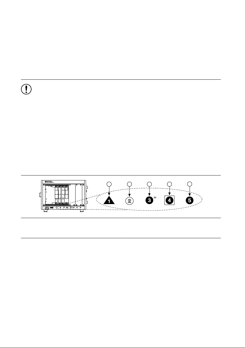
5. Identify a supported slot in the chassis. The following figure shows the symbols that
indicate the slot types.
Figure 1. Chassis Compatibility Symbols
1. PXI Express System Controller Slot
2. PXI Peripheral Slot
3. PXI Express Hybrid Peripheral Slot
4. PXI Express System Timing Slot
5. PXI Express Peripheral Slot
PXIe-5774 modules can be placed in PXI Express peripheral slots, PXI Express hybrid
peripheral slots, or PXI Express system timing slots.
6. Touch any metal part of the chassis to discharge static electricity.
7. Ensure that the ejector handle is in the downward (unlatched) position.
8. Place the module edges into the module guides at the top and bottom of the chassis. Slide
the module into the slot until it is fully inserted.
PXIe-5774 Getting Started Guide | © National Instruments | 5
Page 6

Figure 2. Module Installation
2
3
NI PXIe-1075
1
1. Chassis
2. Hardware Module
3. Ejector Handle in Downward (Unlatched) Position
9. Latch the module in place by pulling up on the ejector handle.
10. Secure the module front panel to the chassis using the front-panel mounting screws.
Note Tightening the top and bottom mounting screws increases mechanical
stability and also electrically connects the front panel to the chassis, which can
improve the signal quality and electromagnetic performance.
11. Cover all empty slots using EMC filler panels or fill using slot blockers to maximize
cooling air flow, depending on your application.
12. Power on the chassis.
Installing the Ferrite on the DIO Cable
Notice To ensure the specified EMC performance, install the snap-on ferrite bead
(National Instruments part number 781233-02) in accordance with these instructions.
1. Open the ferrite bead and place the cable inside the center of the bead. Ensure the ferrite
bead is as close to where the cable connects to the PXIe-5774 as practical.
2. Close the ferrite bead until the locking tabs engage securely.
6 | ni.com | PXIe-5774 Getting Started Guide
Page 7

Figure 3. Snap-On Ferrite Bead Installation
1
2
1. Molex™ Nano-Pitch I/O™ connector
2. Ferrite
PXIe-5774 Front Panel and Pinout
PXIe-5774 Front Panel
The following figure shows the PXIe-5774 front panel.
PXIe-5774 Getting Started Guide | © National Instruments | 7
Page 8

12-Bit, 6.4 GS/s
PXIe-5774
FlexRIO Digitizer
DIO
±3 V
MAX
REF/
CLK
IN
AI 0
AI 1
TRIG
IN
TRIG
OUT
5 Vpp
MAX
±6 V
MAX
3.3 V
LVTTL
Figure 4. PXIe-5774 Front Panel
The following table describes the signal connections for the PXIe-5774.
Connector Description Function
DIO Molex Nano-Pitch DIO
connector
Multi-signal DIO connector that provides
access to FPGA multi-gigabit transceivers
(MGTs) and general-purpose LVCMOS
signals.
AI 0 Standard SMA female connector Analog input connection.
AI 1
8 | ni.com | PXIe-5774 Getting Started Guide
Page 9

Connector Description Function
A1
A2
A3
A4
A5
A6
A7
A8
A9
A10
A11
A12
A13
A14
A15
A16
A17
A18
A19
A20
A21
B1
B2
B3
B4
B5
B6
B7
B8
B9
B10
B11
B12
B13
B14
B15
B16
B17
B18
B19
B20
B21
Reserved
GND
MGT Rx+ 0
MGT Rx– 0
GND
MGT Rx+ 1
MGT Rx– 1
GND
DIO 4
DIO 5
GND
DIO 0
DIO 1
GND
MGT Rx+ 2
MGT Rx– 2
GND
MGT Rx+ 3
MGT Rx– 3
GND
5.0 V
5 V
GND
MGT Tx+ 0
MGT Tx– 0
GND
MGT Tx+ 1
MGT Tx– 1
GND
DIO 6
DIO 7
GND
DIO 2
DIO 3
GND
MGT Tx+ 2
MGT Tx– 2
GND
MGT Tx+ 3
MGT Tx– 3
GND
Reserved
REF/CLK IN Standard SMA female connector Input for an external Reference Clock or
Sample Clock.
TRIG IN Standard SMA female connector Analog IN trigger.
TRIG OUT Standard SMA female connector Digital OUT trigger.
Digital I/O Pinout
The following figure shows the Digital I/O (DIO) connector pinout.
Figure 5. Digital I/O Connector
The following table lists the available pins on the DIO connector.
MGT Tx± <0..3> Xilinx UltraScale GTH Output
MGT Rx± <0..3> Xilinx UltraScale GTH Input
Signal Type Direction
PXIe-5774 Getting Started Guide | © National Instruments | 9
Page 10

Signal Type Direction
DIO <0..7> Single-ended Bidirectional
5.0 V DC Output
GND Ground —
Notice The maximum input signal levels are valid only when the module is
powered on. To avoid permanent damage to the PXIe-5774, do not apply a signal to
the device when the module is powered down.
Notice Connections that exceed any of the maximum ratings of any connector on
the PXIe-5774 can damage the device and the system. NI is not liable for any
damage resulting from such connections.
Configuring the PXIe-5774 in MAX
Use Measurement & Automation Explorer (MAX) to configure your NI hardware. MAX
informs other programs about which NI hardware products are in the system and how they are
configured. MAX is automatically installed with FlexRIO.
1. Launch MAX.
2. In the configuration tree, expand Devices and Interfaces to see the list of installed NI
hardware.
Installed modules appear under the name of their associated chassis.
3. Expand your Chassis tree item.
MAX lists all modules installed in the chassis. Your default names may vary.
Note If you do not see your module listed, press <F5> to refresh the list of
installed modules. If the module is still not listed, power off the system, ensure
the module is correctly installed, and restart.
4. Record the identifier MAX assigns to the hardware. Use this identifier when
programming the PXIe-5774.
5. Self-test the hardware by selecting the item in the configuration tree and clicking Self-
Test in the MAX toolbar.
The MAX self-test performs a basic verification of hardware resources.
FlexRIO Examples
FlexRIO includes several example applications for LabVIEW. These examples serve as
interactive tools, programming models, and as building blocks in your own applications.
10 | ni.com | PXIe-5774 Getting Started Guide
Page 11

Accessing FlexRIO Examples
DIO Connector
(Front Panel)
Adapter Module
Connector
+5 V
+1.8 V
+12 V
GPIO
Configuration, GPIO
MGTs
Reference Clock
Power Supplies
Flash
FPGA
PXIe Connectors
PXI Triggers
Clk 100
DStarB, DStarC
Gen3 x8 PCIe
+12 V, +3.3 V
+12 V
Clk 10
Module Clocking
Synchronization
MGTs
DRAM Bank 0
(2 GB)
DRAM Bank 1
(2 GB)
FlexRIO examples are available in LabVIEW's NI Example Finder. Complete the following
steps to access the examples by task.
1. In LabVIEW, click Help»Find Examples.
2. In the NI Example Finder window that appears, click Hardware Input and Output»
FlexRIO.
The examples are sorted by task. Click on an example and refer to the Information
window for a description of the example. Refer the Requirements window for a list of
hardware devices that can run the example.
You can also click the Search tab to search all installed examples by keyword. For
example, search for FlexRIO to locate all FlexRIO examples.
Examples also are available online that demonstrate FlexRIO basics, such as using DRAM,
acquiring data from adapter modules, and performing high throughput streaming. Refer to
ni.com/examples for these examples and for more information.
Block Diagram
The following figure shows a block diagram of the carrier portion of the PXIe-5774.
Figure 6. Carrier Block Diagram (KU040 and KU060)
PXIe-5774 Getting Started Guide | © National Instruments | 11
Page 12

The following figure shows a block diagram of the I/O portion of the PXIe-5774.
EXTERNAL REF/SCLK
CLK IN SMA
AI1 SMA
ADC12DJ3200
Dual 12-bit, 3.2 GS/s
Single 12-bit, 6.4 GS/s
AI0 SMA
ANALOG INPUT
Input Range
Selection
Adapter Module
Connector
CLOCKING
Input Range
Selection
Filter
Filter
Offset
Offset
Amplifier
INPUT TRIGGER
OUTPUT TRIGGER
TRIG IN SMA
TRIG OUT SMA
Amplifier
Comparator
Threshold
DAC
Figure 7. PXIe-5774 Block Diagram
Component-Level Intellectual Property (CLIP)
The LabVIEW FPGA Module includes component-level intellectual property (CLIP) for HDL
IP integration. FlexRIO devices support two types of CLIP: user-defined and socketed.
• User-defined CLIP allows you to insert HDL IP into an FPGA target, enabling VHDL
• Socketed CLIP provides the same IP integration of the user-defined CLIP, but it also
The PXIe-5774 ships with socketed CLIP items that add module I/O to the LabVIEW project.
12 | ni.com | PXIe-5774 Getting Started Guide
code to communicate directly with an FPGA VI.
allows the CLIP to communicate directly with circuitry external to the FPGA. Adapter
module socketed CLIP allows your IP to communicate directly with both the FPGA VI
and the external adapter module connector interface.
Page 13

Making a Measurement
Making a Measurement with LabVIEW
1. Launch LabVIEW.
2. Select Help»Find Example.
3. Open the example VI that you want to use by selecting Hardware Input and Output»
FlexRIO.
4. Follow any setup, configuration, and execution instructions in the VI.
Troubleshooting
If an issue persists after you complete a troubleshooting procedure, contact NI technical
support or visit ni.com/support.
What Should I Do if the PXIe-5774 Doesn't Appear in MAX?
1. In the MAX configuration tree, expand Devices and Interfaces.
2. Expand the Chassis tree to see the list of installed hardware, and press <F5> to refresh
the list.
3. If the module is still not listed, power off the system, ensure that all hardware is correctly
installed, and restart the system.
4. Navigate to the Device Manager.
Operating System Description
Windows 10/8.1 Right-click the Start button, and select Device Manager.
Windows 7 Select Start»Control Panel»Device Manager.
5. Verify the PXIe-5774 appears in the Device Manager.
a) Under an NI entry, confirm that a PXIe-5774 entry appears.
Note If you are using a PC with a device for PXI remote control system,
under System Devices, also confirm that no error conditions appear for the
PCI-to-PCI Bridge.
b) If error conditions appear, reinstall FlexRIO and the PXIe-5774.
What Should I Do if the PXIe-5774 Fails the Self-Test?
1. Restart the system.
2. Launch MAX, and perform the self-test again.
3. Power off the chassis.
4. Reinstall the failed module in a different slot.
PXIe-5774 Getting Started Guide | © National Instruments | 13
Page 14

5. Power on the chassis.
NI PXIe-4112
EXPLORE LEARN CREATE
DISCOVER
Located online at ni.com/manuals
LabVIEW FPGA
Module Help
Learn LabVIEW Basics
the application development
environment (ADE)
for your application.
about hardware features
or review device
specifications.
custom applications with
an application programming
interface (API).
PXIe-5774
Specifications
FlexRIO Module
Examples
FlexRIO Help
Located using the NI Example Finder
Services
ni.com/services
NI Community
ni.com/community
Support
ni.com/support
FlexRIO
ni.com/flexrio
more about your products through ni.com.
6. Perform the self-test again.
Where to Go Next
Refer to the following figure for information about other product tasks and associated
resources for those tasks.
Worldwide Support and Services
The NI website is your complete resource for technical support. At ni.com/support, you have
access to everything from troubleshooting and application development self-help resources to
email and phone assistance from NI Application Engineers.
Visit ni.com/services for information about the services NI offers.
Visit ni.com/register to register your NI product. Product registration facilitates technical
support and ensures that you receive important information updates from NI.
NI corporate headquarters is located at 11500 North Mopac Expressway, Austin, Texas,
78759-3504. NI also has offices located around the world. For support in the United States,
create your service request at ni.com/support or dial 1 866 ASK MYNI (275 6964). For
14 | ni.com | PXIe-5774 Getting Started Guide
Page 15

support outside the United States, visit the Worldwide Offices section of ni.com/niglobal to
access the branch office websites, which provide up-to-date contact information.
PXIe-5774 Getting Started Guide | © National Instruments | 15
Page 16

Information is subject to change without notice. Refer to the NI Trademarks and Logo Guidelines at ni.com/trademarks for
information on NI trademarks. Other product and company names mentioned herein are trademarks or trade names of their
respective companies. For patents covering NI products/technology, refer to the appropriate location: Help»Patents in your
software, the patents.txt file on your media, or the National Instruments Patent Notice at ni.com/patents. You can find
information about end-user license agreements (EULAs) and third-party legal notices in the readme file for your NI product. Refer
to the Export Compliance Information at ni.com/legal/export-compliance for the NI global trade compliance policy and how
to obtain relevant HTS codes, ECCNs, and other import/export data. NI MAKES NO EXPRESS OR IMPLIED WARRANTIES AS
TO THE ACCURACY OF THE INFORMATION CONTAINED HEREIN AND SHALL NOT BE LIABLE FOR ANY ERRORS. U.S.
Government Customers: The data contained in this manual was developed at private expense and is subject to the applicable
limited rights and restricted data rights as set forth in FAR 52.227-14, DFAR 252.227-7014, and DFAR 252.227-7015.
© 2019 National Instruments. All rights reserved.
377869A-01 March 14, 2019
 Loading...