

Page 1
GETTING STARTED GUIDE
NI PXIe-5630
6 GHz T/R Two-Port Vector Network Analyzer
Note Before you begin, install and configure your chassis and controller.
This document explains how to install, configure, and test the NI PXIe-5630 (NI 5630). The
NI 5630 is a 6 GHz, 2-port vector network analyzer (VNA) with support for vector
measurements of transmission and reflection (T/R) coefficients. The NI 5630 ships with the
NI-VNA instrument driver, which you can use to program the device.
To access NI 5630 documentation, navigate to Start»All Programs»National Instruments»
NI-VNA»Documentation.
The specifications document for your device is installed with the driver software. Refer to
ni.com/manuals for the most recent specifications for your device.
Caution The protection provided by this product may be impaired if it is used in a
manner not described in this document.
Contents
Electromagnetic Compatibility Guidelines...............................................................................2
Verifying the System Requirements......................................................................................... 2
Unpacking the Kit.....................................................................................................................2
Verifying the Kit Contents................................................................................................ 3
Preparing the Environment....................................................................................................... 4
Installing the Software.............................................................................................................. 5
Installing the NI 5630............................................................................................................... 5
Connecting Signals........................................................................................................... 7
Configuring the NI 5630 in MAX...........................................................................................11
Programming the NI 5630...................................................................................................... 12
NI-VNA Examples......................................................................................................... 12
Making Uncalibrated Measurements with the NI 5630..........................................................13
Calibrating the NI 5630.......................................................................................................... 13
Making Calibrated Measurements with the NI 5630..............................................................14
Troubleshooting...................................................................................................................... 15
What Should I Do if the Module Fails the Self-Test?.....................................................15
Why Is the ACCESS LED Off When the Chassis is On?...............................................15
What Should I Do if the NI 5630 Doesn't Appear in MAX?..........................................15
Where to Go Next................................................................................................................... 17
Worldwide Support and Services............................................................................................ 17
Page 2
Electromagnetic Compatibility Guidelines
This product was tested and complies with the regulatory requirements and limits for
electromagnetic compatibility (EMC) stated in the product specifications. These requirements
and limits are designed to provide reasonable protection against harmful interference when the
product is operated in the intended operational electromagnetic environment.
This product is intended for use in industrial locations. However, harmful interference may
occur in some installations, when the product is connected to a peripheral device or test object,
or if the product is used in residential or commercial areas. To minimize interference with
radio and television reception and prevent unacceptable performance degradation, install and
use this product in strict accordance with the instructions in the product documentation.
Furthermore, any modifications to the product not expressly approved by National Instruments
could void your authority to operate it under your local regulatory rules.
Caution To ensure the specified EMC performance, operate this product only with
shielded cables and accessories.
Caution To ensure the specified EMC performance, the length of all I/O cables
must be no longer than 3 m (10 ft).
Verifying the System Requirements
To use the NI-VNA instrument driver, your system must meet certain requirements.
For more information about minimum system requirements, recommended system, and
supported application development environments (ADEs), refer to the product readme, which
is available on the driver software media or online at ni.com/updates.
Unpacking the Kit
Caution To prevent electrostatic discharge (ESD) from damaging the device,
ground yourself using a grounding strap or by holding a grounded object, such as
your computer chassis.
1. Touch the antistatic package to a metal part of the computer chassis.
2. Remove the device from the package and inspect the device for loose components or any
other sign of damage.
Caution Never touch the exposed pins of connectors.
Notify NI if the device appears damaged in any way. Do not install a damaged device.
3. Visually ensure that the inner and outer center conductors of PORT 1 and PORT 2 are not
damaged and are centered in the middle of the outer connector conductor.
4. Unpack any other items and documentation from the kit.
Store the device in the antistatic package when the device is not in use.
| ni.com | NI PXIe-5630 Getting Started Guide
2
Page 3
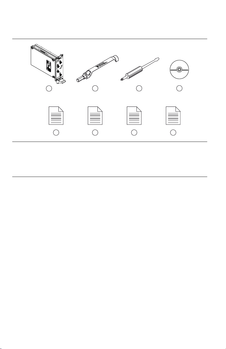
Verifying the Kit Contents
2 3
4
5 6 7 8
1
Figure 1. NI 5630 Kit Contents
1. NI PXIe-5630 Vector Network Analyzer device
2. SMA Driver Bit, part number 190487A-01
3. 1/8 in. Combination Phillips/Flathead Screwdriver,
part number 772006-01
4. NI-VNA Driver Software DVD
5. Read Me First: Safety and Electromagnetic
Compatibility
6. Maintain Forced-Air Cooling Note to Users
7. NI PXIe-5630 Getting Started Guide (this
document)
8. NI 5630 Calibration Certificate
Other Equipment
There are several required items not included in your device kit that you need to operate the
NI 5630. Your application may require additional items not included in your kit to install or
operate your device.
Required Items
• A PXI Express chassis and chassis documentation. The NI PXIe-1075 chassis is one
available option for your device. For more information about compatible chassis options,
refer to ni.com.
• An embedded controller or MXI controller system that meets the system requirements
specified in this guide and chassis documentation.
• 0.9 N · m (8 in-lb) torque wrench
Optional Items
• PXI Chassis Slot Blocker kit (NI part number 199198-01)
• NI 2598 Dual 26 GHz Transfer Switch module (NI part number 778572-98)
• The following accessories available on the NI 5630 product page at ni.com/products:
NI PXIe-5630 Getting Started Guide
| © National Instruments | 3
Page 4
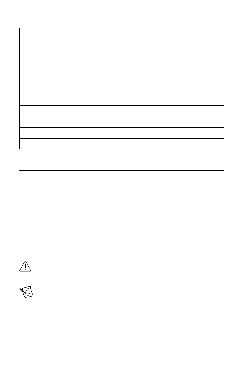
Table 1. NI 5630 Accessories
Accessory Part Number
Manual VNA Calibration Kit, K-Type 781587-01
Manual VNA Calibration Kit, N-Type 781588-01
Automatic VNA Calibration Kit, K-Type, Male-Female, 70 KHz to 9 GHz 782364-01
Phase-Equal Precision Adapter Kit, K-Type 781595-01
Phase-Equal Precision Adapter Kit, N-Type 781596-01
Precision Coaxial Cable, 0.6 m, K-Type, Male-Male 781607-01
Precision Coaxial Cable, 0.6 m, K-Type, Male-Female 781608-01
Precision Coaxial Cable, 0.6 m, K-Type Male to N-Type Male 781609-01
Precision Coaxial Cable, 0.6 m, K-Type Male to N-Type Female 781610-01
Calibrated 5/16" Torque Wrench, 8 in-lbs (0.9 Nm) 781615-01
Preparing the Environment
Ensure that the environment you are using the NI 5630 in meets the following specifications.
............................................................................Operating ambient temperature
(IEC-60068-2-1, IEC-60068-2-2)
............................................................................Operating relative humidity
(IEC-60068-2-56)
............................................................................Maximum altitude 2,000 m (800 mbar) (at 25 °C ambient
............................................................................Pollution Degree 2
Indoor use only.
Caution Clean the hardware with a soft, nonmetallic brush. Make sure that the
hardware is completely dry and free from contaminants before returning it to
service.
Note Refer to the NI PXIe-5630 Specifications at ni.com/manuals for complete
specifications.
4 | ni.com | NI PXIe-5630 Getting Started Guide
0 °C to 55 °C
10% to 90%, noncondensing
temperature)
Page 5
Installing the Software
NI PXIe-1062Q
1
2 3
4
5
You must be an Administrator to install NI software on your computer.
1. Install an ADE, such as LabVIEW or LabWindows™/CVI™.
2. Insert the driver software media into your computer. The installer should open
automatically.
If the installation window does not appear, navigate to the drive, double-click it, and
double-click autorun.exe.
3. Follow the instructions in the installation prompts.
Note Windows users may see access and security messages during
installation. Accept the prompts to complete the installation.
4. When the installer completes, select Restart in the dialog box that prompts you to restart,
shut down, or restart later.
Installing the NI 5630
Caution To prevent damage to the device caused by ESD or contamination, handle
the device using the edges or the metal bracket.
1. Ensure the AC power source is connected to the chassis before installing the modules.
The AC power cord grounds the chassis and protects it from electrical damage while you
install the modules.
2. Power off the chassis.
3. Inspect the slot pins on the chassis backplane for any bends or damage prior to
installation. Do not install a module if the backplane is damaged.
4. Remove the black plastic connectors from all the captive screws on the module front
panel.
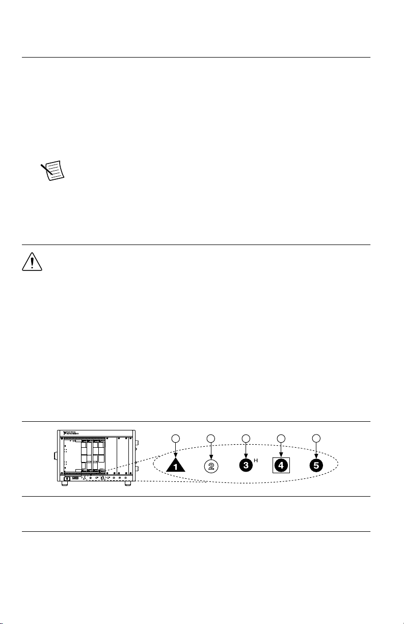
5. Identify a supported slot in the chassis. The following figure shows the symbols that
indicate the slot types.
Figure 2. Chassis Compatibility Symbols
1. PXI Express System Controller Slot
2. PXI Peripheral Slot
3. PXI Express Hybrid Peripheral Slot
4. PXI Express System Timing Slot
5. PXI Express Peripheral Slot
The NI 5630 can be placed in PXI Express peripheral slots or PXI Express Hybrid
peripheral slots.
NI PXIe-5630 Getting Started Guide
| © National Instruments | 5
Page 6
6. Touch any metal part of the chassis to discharge static electricity.
2
3
NI PXIe-1075
1
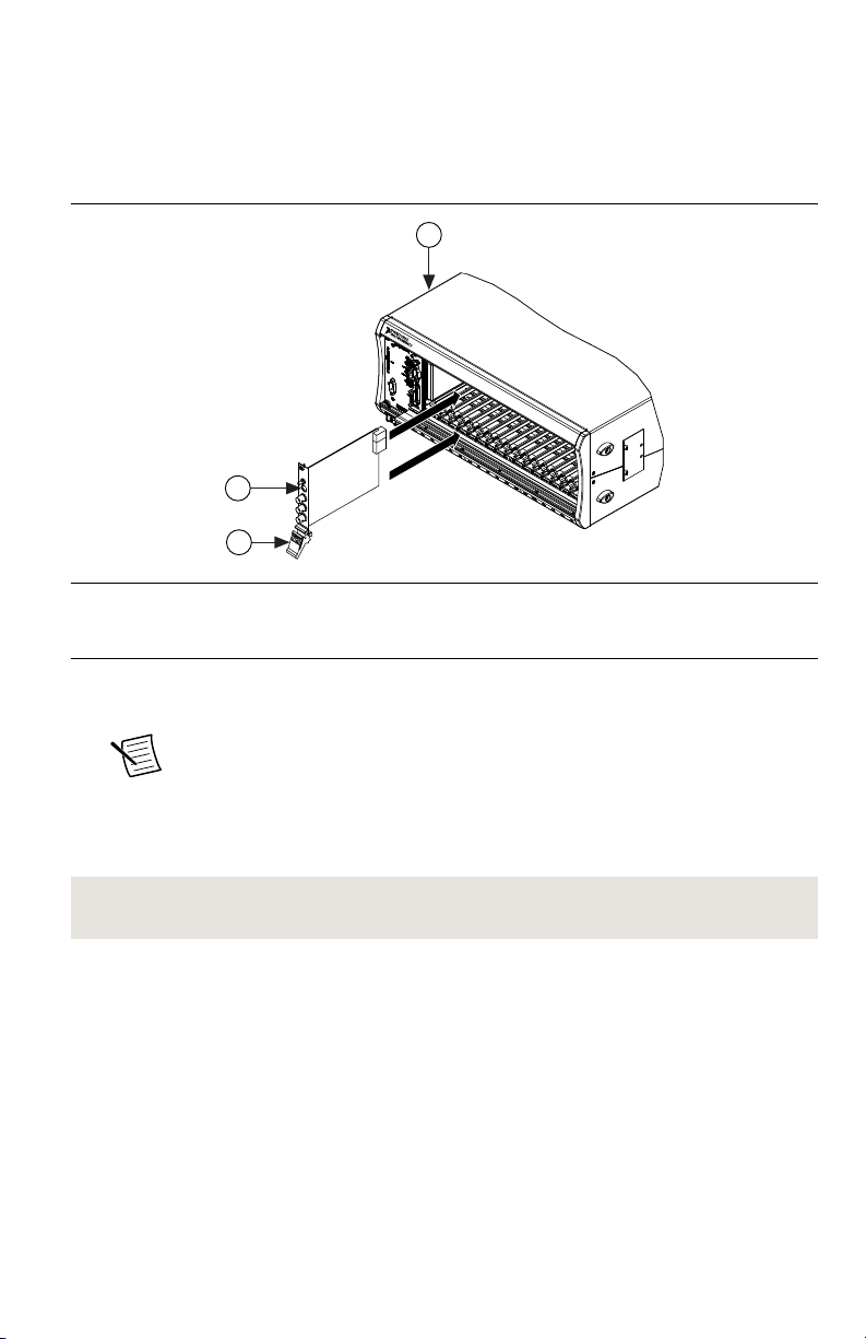
7. Ensure that the ejector handle is in the unlatched (downward) position.
8. Place the module edges into the module guides at the top and bottom of the chassis. Slide
the device into the slot until it is fully inserted.
Figure 3. Module Installation
1. Chassis
2. Hardware Module
3. Ejector Handle in Down (Unlatched) Position
9. Latch the module in place by pulling up on the ejector handle.
10. Secure the device front panel to the chassis using the front-panel mounting screws.
Note Tightening the top and bottom mounting screws increases mechanical
stability and also electrically connects the front panel to the chassis, which can
improve the signal quality and electromagnetic performance.
11. Cover all empty slots using filler panels or slot blockers to maximize cooling air flow.
12. Power on the chassis.
Related Information
Installing the Software on page 5
| ni.com | NI PXIe-5630 Getting Started Guide
6
Page 7

Connecting Signals
1
2 3
4 4
Use appropriate shielded cables to connect signals to the NI vector network analyzer to ensure
you achieve the best measurement accuracy possible.
Unsuitable cabling can adversely affect the vector error correction, producing unreliable and
misleading results. Precision coaxial cables are available for purchase from ni.com. Ensure
you take the following precautions when connecting signals to the NI 5630.
• Use phase-stable cables to make connections with the NI 5630. Phase-stable cables help
ensure that the reference plane remains stable across shifts in cable position after
calibration.
• Maintain placement of any accessories or cables that you attach to the NI 5630 to ensure
that the reference plane remains constant between calibration and measurement.
Tip You can also use phase-equal adapters after calibration to preserve the
reference plane.
The following figure shows an example of the reference plane for a male and female
connector.
Figure 4. Connector Reference Plane and Pin Depth
1. Reference Plane
2. Female Connector
3. Male Connector
4. Pin Depth
Related Information
Refer to the NI Vector Network Analyzers Help for more information about reference planes
and pin depth.
Direct Connections to the NI 5630
The NI 5630 is a precision RF instrument that is sensitive to ESD and transients. Ensure you
take the following precautions when making direct connections to the NI 5630 to avoid
damaging the device.
NI PXIe-5630 Getting Started Guide
| © National Instruments | 7
Page 8

Caution Apply external signals only while the NI 5630 is powered on. Applying
10 MHz
-10 dBm to +3 dBm
50 Ω
+23 dBm MAX
50 VDC
50 Ω
+23 dBm MAX
50 VDC
50 Ω
PORT 1
REF IN
TTL
PFI 0
NI PXIe-5630
10 MHz - 6 GHz Vector Network Analyzer
ACCESS ACTIVE
PORT 2
TRANSMISSION
REFLECTION
ESD
SENSITIVE
external signals while the device is powered off may cause damage.
• Ensure you are properly grounded when manipulating cables or antennas connected to the
NI 5630 PORT 1 or PORT 2 connector.
• If you are using noninsulated devices, such as a noninsulated RF antenna, ensure the
devices are maintained in a static-free environment.
• If you are using an active device, such as a preamplifier or switch routed to the NI 5630
PORT 1 or PORT 2 connector, ensure that there are no signal transients greater than the
RF and DC specifications for the device that are being generated and sourced to the
NI 5630 PORT 1 or PORT 2 connector.
NI 5630 Front Panel
The NI 5630 contains four connectors and two LEDs.
Figure 5. NI PXIe-5630 Front Panel
8 | ni.com | NI PXIe-5630 Getting Started Guide
Page 9

Table 2. Device Front Panel Icon Definitions
Refer to the user documentation for required maintenance measures to ensure user
safety and/or preserve the specified EMC performance.
The signal pins of this product's input/output ports can be damaged if subjected to
ESD. To prevent damage, turn off power to the product before connecting cables and
employ industry-standard ESD prevention measures during installation, maintenance,
and operation.
Table 3. NI 5630 Front Panel Connectors
Connector Use
PORT 1 Input/output terminal for NI 5630 measurements.
REF IN Input terminal for an external reference signal for the NI 5630.
PFI 0 Input terminal for an external trigger signal.
PORT 2 Input terminal for NI 5630 measurements.
Table 4. NI 5630 LEDs
LED Indication
ACCESS Indicates the basic hardware status of the NI 5630.
OFF—The device is not yet functional.
AMBER—The device is being accessed. Accessed means that the device is being
communicated with over the PXI Express bus.
GREEN—The device is ready to be programmed by NI-VNA.
RED—The device has detected a hardware error, such as a hardware failure. The
LED remains red until the error condition is removed.
ACTIVE Indicates the state of the NI 5630.
OFF—The device is not yet functional.
AMBER—The device is armed and waiting for a trigger.
GREEN—The device has received a Start Trigger. This state also indicates that
the device is making a measurement.
RED—The device has detected a spurious error, such as when the PLL becomes
unlocked. The LED remains red until the error condition is removed.
NI PXIe-5630 Getting Started Guide | © National Instruments | 9
Page 10

Connector Care
The NI 5630 is a high-accuracy precision laboratory device and should be carefully handled.
Follow the precautions listed in this section when handling or connecting devices. Complying
with these precautions guarantees longer component life and lower equipment downtime
because of connector or device failure.
Tighten Connectors Without Rotating the Center Pin
Never tighten the connectors, adapters, or cables such that the center pin rotates. Damage
occurs to the mating plane surfaces if the center pin rotates.
Avoid Touching Connectors with Bare Hands
Avoid touching connector mating planes with bare hands. Natural skin oils and microscopic
dirt particles are difficult to remove.
Observe Pin Depth of Mating Connectors
Make sure to use the proper connectors to mate with the NI 5630. NI recommends that you use
precision or instrument or metrology grade Type-K, 2.92 mm, 3.5 mm, or SMA connectors.
Always check the point depth of a connector with a pin depth gauge before use to determine
whether the pin depth is within the specified range.
Avoid Lateral Pressure
Never put lateral pressure on the center pin of the connector.
Always Torque Connectors to 0.9 N · m Using a Torque Wrench
Do not overtorque connectors; doing so may damage the connector center pin. Always use a
0.9 N · m (8 in-lb) torque wrench when tightening 2.92 mm, 3.5 mm, and SMA connectors.
Finger-tighten N-type connectors. Never use pliers.
Avoid Mechanical Shock
Precision connectors are designed to withstand years of normal bench handling. Handle the
connectors carefully and avoid dropping them. Mechanical shock significantly reduces their
service life.
Avoid Applying Excessive Power
The NI 5630 is rated for a specific maximum continuous input power. Exceeding the
maximum input power level permanently damages the internal components. Before making
connections, verify the maximum input levels labeled below the ports on the module front
panel.
Clean Connectors Carefully
Dirt and other contamination on the connector interfaces can affect the performance of the RF
components. To clean the connector interfaces, use only pure isopropyl alcohol as a cleaning
solvent. Do not use excessive amounts of alcohol, as this prolongs drying time. Apply the
alcohol with a foam-tipped swab instead of cotton swabs, because the cotton can become
lodged in the connector.
| ni.com | NI PXIe-5630 Getting Started Guide
10
Page 11

Use low-pressure compressed air to remove foreign particles and to dry the connector. After
cleaning, verify that the center pin has not been bent or damaged.
Store Connectors Properly
When not in use, keep the connectors covered with the dust cap included in the NI 5630
shipping kit.
Configuring the NI 5630 in MAX
Use Measurement & Automation Explorer (MAX) to configure your National Instruments
hardware. MAX informs other programs about which devices reside in the system and how
they are configured. MAX is automatically installed with NI-VNA.
1. Launch MAX.
2. In the Configuration pane, double-click Devices and Interfaces to see the list of installed
devices.
Installed devices appear under the name of their associated chassis.
3. Expand your Chassis tree item.
MAX lists all devices installed in the chassis. Your default device names may vary.
Note If you do not see your device listed, press <F5> to refresh the list of
installed devices. If the device is still not listed, power off the system, ensure
the device is correctly installed, and restart.
4. Record the device identifier MAX assigns to the hardware. Use this identifier when
programming the NI 5630.
5. Self-test the device by selecting the device in the configuration tree and clicking Self-
Test in the MAX toolbar.
The MAX self-test performs a basic verification of hardware resources.
Related Information
What Should I Do if the Module Fails the Self-Test? on page 15
What Should I Do if the NI 5630 Doesn't Appear in MAX? on page 15
NI PXIe-5630 Getting Started Guide
| © National Instruments | 11
Page 12

Programming the NI 5630
You can acquire data interactively with the NI 5630 using the NI-VNA soft front panel (SFP),
or you can control the device programmatically using the NI-VNA instrument driver. You can
then use NI-VNA to program the device in the ADE of your choice.
Table 5. NI 5630 Programming Options
Application
Programming
Interface (API)
Location Description
NI-VNA SFP Available from the Start menu at Start»
All Programs»National Instruments»
NI-VNA»NI-VNA Soft Front Panel.
NI-VNA
Instrument Driver
LabVIEW—Available on the LabVIEW
Functions palette at Measurement I/O»
NI-VNA.
A software representation of
a traditional benchtop vector
network analyzer.
Features a set of functions
and attributes that exercise
all the functionality of the
NI 5630, including
C or LabWindows/CVI—Available at
Program Files\IVI Foundation
\IVI\Drivers\niVNA.
Microsoft Visual C/C++—Use
examples located in the <NIDocDir>
\NI-VNA\examples directory, where
<NIDocDir> is one of the following
configuration, control, and
other device-specific
functions.
You can modify an NI-VNA
C example to create an
application with Microsoft
Visual C/C++.
directories:
• Windows XP—Documents and
Settings\All Users\Shared
Documents\National
Instruments
• Windows 7/Vista—Users
\Public\Documents
\National Instruments
Related Information
Refer to the Getting Started section of the NI Vector Network Analyzers Help for detailed
instructions about how to acquire data in a specific ADE.
Refer to the Creating an Application with Microsoft Visual C/C++ topic of the NI Vector
Network Analyzers Help to manually add all required include and library files to the project.
NI-VNA Examples
Examples demonstrate the functionality of the device and serve as programming models and
building blocks for your own applications. The NI Example Finder is a utility available for
| ni.com | NI PXIe-5630 Getting Started Guide
12
Page 13

some ADEs that organizes examples into categories and allows you to easily browse and
search installed examples. You can see descriptions and compatible hardware models for each
example or see all the examples compatible with one particular hardware model.
Table 6. Locating NI-VNA Examples
ADE How to Locate Examples
LabVIEW or
LabWindows/CVI
ANSI C or Microsoft
Visual C/C++
Locate examples with the NI Example Finder. Within LabVIEW
or LabWindows/CVI, select Help»Find Examples and navigate
to Hardware Input and Output»Modular Instruments.
Locate examples in the <NIDocDir>\NI-VNA\examples
directory, where <NIDocDir> is one of the following directories:
• Windows 8/7/Vista—Users\Public\Documents
\National Instruments
• Windows XP—Documents and Settings\All
Users\Documents\National Instruments
Making Uncalibrated Measurements with the NI 5630
Performing uncalibrated measurements with the NI 5630 can be useful for measuring device
raw performance, custom measurement configuration, and other specialized measurements.
You can perform uncalibrated measurements using the NI-VNA Soft Front Panel (SFP) or the
NI-VNA driver API.
1. Prepare for the measurement.
a) Warm up the device and the DUT as specified in the device specifications.
b) Make signal connections as directed in the Connecting Signals section.
c) Verify that the device is within the factory calibration interval.
2. Set up an initial, uncalibrated measurement.
a) Preset the NI 5630.
b) Configure the source parameters, including reference frequency, output power, and
IF bandwidth.
c) Connect the DUT to verify setup, cables, adapters, and operation.
d) Select which S-parameter(s) to measure, and choose the display format.
3. Start the measurement.
4. Observe the uncalibrated response.
5. Remove the DUT.
Calibrating the NI 5630
Frequent calibration is particularly important for the NI 5630 because it allows you to remove
certain errors from the actual measurements. Calibration removes errors caused by
NI PXIe-5630 Getting Started Guide
| © National Instruments | 13
Page 14

temperature, test environment, cables, and other test fixture differences. You can perform a
calibration by using either the NI-VNA Soft Front Panel (SFP) or the NI-VNA driver API.
1. Choose whether you want to perform a new calibration or load data saved from a
previous calibration.
2. To perform a new calibration, complete the following steps:
a) Set the measurement parameters such as power, frequency, and number of points.
b) Set IF bandwidth and averaging to minimize noise during calibration.
c) Choose the proper calibration kit or input calibration standard definitions.
Tip Keep the reference plane constant between your initial, uncalibrated
measurement and your calibration setup. The reference plane is
established at the location where the VNA connects to the AutoCal
module or to the calibration standard. For example, your reference plane
may be located at the end of an adapter connected to the end of a precision
cable.
d) Calibrate manually or use automatic calibration.
e) Verify calibration quality using a known verification standard.
Note Do not use the same calibration standards that you used for
calibration to perform the verification.
f) Save the instrument state and calibration.
3. To load a saved calibration, complete the following steps:
a) Select the calibration file.
b) Ensure that the source parameters you specified in step 2b of the Making
Uncalibrated Measurements with the NI 5630 section match those that were used in
the calibration.
Perform a new calibration if the settings do not match.
Related Information
Refer to the NI Vector Network Analyzers Help for more information about reference planes.
Making Calibrated Measurements with the NI 5630
Performing calibrated measurements with the NI 5630 is useful when you need to minimize
sources of error so that you can acquire the most accurate data for your test system. You can
perform calibrated measurements using the NI-VNA Soft Front Panel (SFP) or the NI-VNA
driver API.
1. Measure the DUT.
2. Ensure you are applying the proper correction from the Calibrating the NI 5630 section.
3. Measure and save the DUT parameters.
4. Verify that the calibrated measurement falls within your expected range.
| ni.com | NI PXIe-5630 Getting Started Guide
14
Page 15

Troubleshooting
If an issue persists after you complete a troubleshooting procedure, contact NI technical
support or visit ni.com/support.
What Should I Do if the Module Fails the Self-Test?
1. Restart the system.
2. Launch MAX, and perform the self-test again.
3. Power off the chassis.
4. Reinstall the failed module in a different slot.
5. Power on the chassis.
6. Perform the self-test again.
Related Information
Configuring the NI 5630 in MAX on page 11
Why Is the ACCESS LED Off When the Chassis is On?
The LEDs may not illuminate until the device has been configured in MAX. Before
proceeding, verify that the NI 5630 appears in MAX.
If the ACCESS LED fails to illuminate after you power on the chassis, a problem may exist
with the chassis power rails, a hardware module, or the LED.
Caution Apply external signals only while the NI 5630 is powered on. Applying
external signals while the device is powered off may cause damage.
1. Disconnect any signals from the module front panels.
2. Power off the chassis.
3. Remove the module from the chassis and inspect it for damage. Do not reinstall a
damaged device.
4. Reinstall the module in a different chassis slot.
5. Power on the chassis.
6. Verify that the device appears in MAX.
7. Reset the device in MAX and perform a self-test.
What Should I Do if the NI 5630 Doesn't Appear in MAX?
1. In the MAX Configuration pane, click Devices and Interfaces.
2. Expand the Chassis tree to see the list of installed devices, and press <F5> to refresh the
list.
3. If the module is still not listed, power off the system, ensure that all hardware is correctly
installed, and restart the system.
NI PXIe-5630 Getting Started Guide
| © National Instruments | 15
Page 16

4. Navigate to the Device Manager.
Operating System Description
Windows 8 Right-click the Start screen, and select All apps»Control Panel»
Hardware and Sound»Device Manager.
Windows 7 Select Start»Control Panel»Device Manager.
Windows Vista Select Start»Control Panel»System and Maintenance»Device
Manager.
Windows XP Select Start»Control Panel»System»Hardware»Device
Manager.
5. If you are using a PXI controller, verify that a National Instruments entry appears in the
system device list and that the NI PXIe-5630 is enabled. If the device is disabled, rightclick NI PXIe-5630, and select Enable from the shortcut menu. If you are using a MXI
controller, right-click PCI-to-PCI Bridge, and select Properties from the shortcut menu
to verify that the bridge is enabled.
Related Information
Configuring the NI 5630 in MAX on page 11
16 | ni.com | NI PXIe-5630 Getting Started Guide
Page 17

Where to Go Next
custom applications within
an application programming
interface (API).
NI-VNA Examples*
NI Vector Network
Analyzers Help*
NI-VNA Soft Front Panel
NI-VNA Instrument Driver
about hardware features
or review device
specifications.
more about your products through ni.com.
NI PXIe-5630
Specifications*
NI Vector Network
Analyzers Help*
the application development
environment (ADE)
for your application.
Learn LabVIEW Basics
Getting Started with
LabWindows/CVI
Support
ni.com/support
*This item is also installed with the driver software.
EXPLORE LEARN CREATE
DISCOVER
RF Solutions
ni.com/rf
Services
ni.com/services
NI Community
ni.com/community
Located at ni.com/gettingstarted
Located at ni.com/manuals
Located using the NI Example Finder
Refer to the following figure for information about other product tasks and associated
resources for those tasks.
Tip The NI Vector Network Analyzers Help is an HTML version of a traditional
user manual that includes detailed information about RF fundamentals, device
features, and programming with NI-VNA.
Worldwide Support and Services
The National Instruments website is your complete resource for technical support. At ni.com/
support, you have access to everything from troubleshooting and application development
self-help resources to email and phone assistance from NI Application Engineers.
Visit ni.com/services for NI Factory Installation Services, repairs, extended warranty, and
other services.
NI PXIe-5630 Getting Started Guide
| © National Instruments | 17
Page 18

Visit ni.com/register to register your National Instruments product. Product registration
facilitates technical support and ensures that you receive important information updates from
NI.
A Declaration of Conformity (DoC) is our claim of compliance with the Council of the
European Communities using the manufacturer’s declaration of conformity. This system
affords the user protection for electromagnetic compatibility (EMC) and product safety. You
can obtain the DoC for your product by visiting ni.com/certification. If your product supports
calibration, you can obtain the calibration certificate for your product at ni.com/calibration.
National Instruments corporate headquarters is located at 11500 North Mopac Expressway,
Austin, Texas, 78759-3504. National Instruments also has offices located around the world.
For telephone support in the United States, create your service request at ni.com/support or
dial 1 866 ASK MYNI (275 6964). For telephone support outside the United States, visit the
Worldwide Offices section of ni.com/niglobal to access the branch office websites, which
provide up-to-date contact information, support phone numbers, email addresses, and current
events.
Refer to the NI Trademarks and Logo Guidelines at ni.com/trademarks for information on National Instruments
trademarks. Other product and company names mentioned herein are trademarks or trade names of their respective
companies. For patents covering National Instruments products/technology, refer to the appropriate location: Help»
Patents in your software, the patents.txt file on your media, or the National Instruments Patent Notice at ni.com/
patents. You can find information about end-user license agreements (EULAs) and third-party legal notices in the
readme file for your NI product. Refer to the Export Compliance Information at ni.com/legal/export-compliance for
the National Instruments global trade compliance policy and how to obtain relevant HTS codes, ECCNs, and other
import/export data. NI MAKES NO EXPRESS OR IMPLIED WARRANTIES AS TO THE ACCURACY OF THE
INFORMATION CONTAINED HEREIN AND SHALL NOT BE LIABLE FOR ANY ERRORS. U.S. Government
Customers: The data contained in this manual was developed at private expense and is subject to the applicable limited
rights and restricted data rights as set forth in FAR 52.227-14, DFAR 252.227-7014, and DFAR 252.227-7015.
© 2010—2014 National Instruments. All rights reserved.
375565C-01 Sep14
 Loading...