

Page 1
GETTING STARTED GUIDE
PXIe-5170/5171
250 MS/s, 14-Bit Reconfigur
able Oscilloscope
Note Before you begin, install and configure your chassis and controller.
Caution This icon denotes a caution, which advises you to consult documentation
where this symbol is marked.
Caution You can impair the protection provided by the PXIe-5170/5171 if you use
it in a manner not described in this document.
This document explains how to install, configure, test, and use the PXIe-5170/5171. The
PXIe-5170/5171 ships with the following software options, which you can use to program the
device:
•
NI-SCOPE driver software
•
NI LabVIEW Instrument Design Libraries for Reconfigurable Oscilloscopes (instrument
design libraries)
Contents
Electromagnetic Compatibility Guidelines...............................................................................2
Verifying the System Requirements
..........................................................................................2
Unpacking the Kit..................................................................................................................... 2
Kit Contents...................................................................................................................... 3
Other Equipment....................................................................................................................... 3
Preparing the Environment....................................................................................................... 4
Choosing the Software.............................................................................................................. 4
Software Options...............................................................................................................4
Comparison of Software Features.....................................................................................5
Installing the Software.............................................................................................................. 6
Installing the PXIe-5170/5171.................................................................................................. 7
Front Panel Connectors.....................................................................................................9
Connecting Digital Signals......................................................................................................11
AUX I/O Connector Pinout.............................................................................................11
PXIe-5170/5171 SCB-19 Pinout.....................................................................................12
Configuring the Hardware in MAX........................................................................................ 13
Self-Calibration.......................................................................................................................13
Page 2

First Measurements................................................................................................................. 14
Making a Measurement with Instrument Design Libraries............................................
14
Making a Measurement with NI-SCOPE........................................................................14
Troubleshooting...................................................................................................................... 15
What Should I Do if the PXIe-5170/5171 Doesn't Appear in MAX?............................ 15
What Should I Do if the PXIe-5170/5171 Fails the Self-Test or Self-Calibration?........16
Where To Go Next.................................................................................................................. 16
Worldwide Support and Services............................................................................................17
Electromagnetic Compatibility Guidelines
This product was tested and complies with the regulatory requirements and limits for
electromagnetic compatibility (EMC) stated in the product specifications. These requirements
and limits provide reasonable protection against harmful interference when the product is
operated in the intended operational electromagnetic environment.
This product is intended for use in industrial locations. However, harmful interference may
occur in some installations, when the product is connected to a peripheral device or test object,
or if the product is used in residential or commercial areas. T
o minimize interference with
radio and television reception and prevent unacceptable performance degradation, install and
use this product in strict accordance with the instructions in the product documentation.
Furthermore, any changes or modifications to the product not expressly approved by National
Instruments could void your authority to operate it under your local regulatory rules.
Caution To ensure the specified EMC performance, operate this product only with
shielded cables and accessories. The length of all I/O cables must be no longer than
3 m (10 ft
).
Caution This product may become more sensitive to electromagnetic disturbances
in the operational environment when test leads are attached or when connected to a
test object.
Verifying the System Requirements
To use the PXIe-5170/5171, your system must meet certain requirements.
For more information about minimum system requirements, recommended system
requirements, and supported ADEs, refer to the readme for your selected software support.
Readmes are available on the driver software DVD and online at ni.com/downloads.
Unpacking the Kit
Caution T
o prevent electrostatic discharge (ESD) from damaging the device,
ground yourself using a grounding strap or by holding a grounded object, such as
your computer chassis.
2
| ni.com
| PXIe-5170/5171 Getting Started Guide
Page 3
1. Touch the antistatic package to a metal part of the computer chassis.
2. Remove the device from the package and inspect the device for loose components or any
other sign of damage.
Caution Never touch the exposed pins of connectors.
Note Do not install a device if it appears damaged in any way.
3.
Unpack any other items and documentation from the kit.
Store the device in the antistatic package when the device is not in use.
Kit Contents
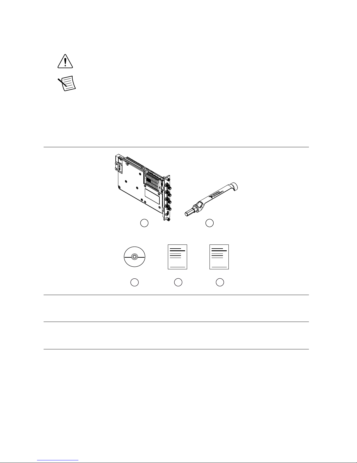
Figure 1. PXIe-5170/5171 Kit Contents
21
4 5
3
1. PXIe-5170/5171 Module
2.
SMA dr
iver bit, part number 780895-01
3. Driver Software DVD
4. PXIe-5170/5171 Getting Started Guide
5. Maintain Forced-Air Cooling Note to Users
Other Equipment
There are several required items not included in your device kit that you need to operate the
PXIe-5170/5171. Your application may require additional items not included in your kit to
install or operate your
PXIe-5170/5171.
Required Items
• A PXI Express chassis and chassis documentation
• A PXI Express embedded controller or PC with MXI controller system that meets the
system requirements specified in this guide and chassis documentation
PXIe-5170/5171 Getting Started Guide | © National Instr
uments | 3
Page 4

Optional Items
• PXI Slot Blocker kit (NI part number 199198-01)
•
SMA (m)-to-SMA (m) coaxial cables, RG-402, 50 Ω, 1 M (NI part number 781845-01)
• SHH19-MH19-AUX shielded single-ended cable, 1 M (NI part number 784091-01)
• SCB-19 connector block (NI part number 783959-01)
Visit ni.com for more information about these additional items.
Preparing the Environment
Ensure the environment in which you are using the PXIe-5170/5171 meets the following
specifications.
Operating environment
Ambient temperature range 0 °C to 45 °C (Tested in accordance with
IEC-60068-2-1 and IEC-60068-2-2. Meets
MIL-PRF-28800F Class 3 low temperature
limit and MIL-PRF-28800F Class 4 high
temperature limit.
)
Relative humidity range 10% to 90%, noncondensing (Tested in
accordance with IEC 60068-2-56.)
Maximum altitude 2,000 m (800 mbar) (at 25 °C ambient
temperature)
Pollution Degree 2
Indoor use only.
Caution You can impair the protection provided by the PXIe-5170/5171 if you use
it in a manner not described in this document.
Note For complete specifications, refer to the specifications document for your
device at ni.com/manuals.
Choosing the Software
Software Options
NI provides multiple software options for interacting with the PXIe-5170/5171: NI-SCOPE
soft front panel (SFP),
NI-SCOPE instrument driver software, and the instrument design
libraries.
4 | ni.com
| PXIe-5170/5171 Getting Started Guide
Page 5
Table 1. PXIe-5170/5171 Software Options
Use Case Software Option
Acquire and analyze data without programming. NI-SCOPE SFP
Create custom measurements and automation
applications.
NI-SCOPE instrument driver
Customize the behavior of the device FPGA to create
application-specific instrument designs.
Instrument design libraries with the
LabVIEW FPGA Module
Note You can use a combination of these software options for your application.
However
, when using the NI-SCOPE driver and the instrument design libraries in a
single application, only one option can access the device at a time.
Related Information
Installing the Software on page
6
Visit ni.com/info and enter the Info Code IDLintro for more information about instrument
design libraries and how to use them.
Comparison of Software Features
NI-SCOPE instrument driver software and the instrument design libraries vary in the features
they support.
Table 2. Comparison of Softw
are Features
Feature NI-SCOPE Instrument Design Libraries
Customization of
onboard FPGA
Supported using
the instrument
driver FPGA
extensions
Supported using the LabVIEW FPGA Module
Source availability Closed source Open source
LabVIEW support Yes Yes
C/C++/C# support Yes Using the NI LabVIEW Application Builder, you
can compile LabVIEW code into custom DLLs for
use with other application development
environments (ADEs).
PXIe-5170/5171 Getting Started Guide | © National Instruments | 5
Page 6
Table 2. Comparison of Softw
are Features (Continued)
Feature NI-SCOPE Instrument Design Libraries
NI-SCOPE SFP
support
Yes No
LabVIEW examples
or sample projects
Yes Includes LabVIEW sample projects, with
additional examples available at
ni.com/software-designed-instruments.
Related Information
Refer to ni.com/labview/fpga to learn more about the benefits of using LabVIEW FPGA
Module to customize your device.
Installing the Softw
are
Close all programs before installing the software. NI recommends installing your software
before installing the PXIe-5170/5171 hardware.
Install your software in the following order:
1.
Install the latest service packs for your operating system.
2. Install NI LabVIEW.
Refer to the LabVIEW Installation Guide for installation instructions for LabVIEW and
system requirements for LabVIEW software. Refer to the LabVIEW Upgrade Notes for
additional information about upgrading to the most recent version of LabVIEW for
Windows.
3. (Optional) Install NI LabVIEW FPGA Module.
Refer to the LabVIEW FPGA Module Release and Upgrade Notes for installation
instructions and information about getting started with the LabVIEW FPGA Module.
Note Installation of the LabVIEW FPGA Module is required to customize the
behavior of the device FPGA if you are using the instrument design libraries.
4. (Recommended) Install the latest service pack for LabVIEW and any LabVIEW modules
you are using.
5. Insert the driver software DVD into the DVD drive.
The driver software installer should open automatically
. If the installation window does
not appear, navigate to the DVD drive, double-click the drive, and double-click
autorun.exe.
Note You can also download the software from ni.com/downloads
.
6. Follow the instructions in the installation prompts to install the default installation.
6 | ni.com
| PXIe-5170/5171 Getting Started Guide
Page 7

Windows users may see access and security messages during installation. Accept the
prompts to complete the installation.
Note For troubleshooting information, contact NI technical support or visit
ni.com/support.
7. When the installer completes, restart your system.
Installing the PXIe-5170/5171
Caution To prevent damage to the PXIe-5170/5171 caused by ESD or
contamination, handle the module using the edges or the metal bracket.
Y
ou must install the software before installing the hardware.
Before you install the hardware, refer to the guidelines in the Maintain Forced-Air Cooling
Note to Users included in the PXIe-5170/5171 kit to ensure that the PXIe-5170/5171 can cool
itself effectively. This document is also available at ni.com/manuals.
The PXIe-5170/5171 is a single-slot module with one backplane connector. The module may
be installed into any PXI Express-compatible slot.
1. Ensure the AC power source is connected to the chassis before installing the
PXIe-5170/5171. The AC power cord grounds the chassis and protects it from electrical
damage while you install the PXIe-5170/5171.
2. Power off the chassis.
3. Inspect the slot pins on the chassis backplane for any bends or damage prior to
installation. Do not install a module if the backplane is damaged.
4. If the chassis has multiple fan speed settings, ensure the fans are set to the highest setting.
Note Inadequate air circulation could cause the temperature inside the chassis
to rise above the optimal operating temperature for the PXIe-5170/5171,
potentially causing thermal shutdown, shorter life spans, or improper
performance.
5.
Position the chassis so that inlet and outlet vents are not obstructed.
For more information about optimal chassis positioning, refer to the chassis
documentation.
6. Remove the black plastic covers from all the captive screws on the module front panel.
7. Identify a supported slot in the chassis. The following figure shows the symbols that
indicate the slot types.
PXIe-5170/5171 Getting Started Guide | © National Instr
uments | 7
Page 8

Figure 2. Chassis Compatibility Symbols
NI PXIe-1062Q
1
2 3
4
5
1. PXI Express System Controller Slot
2. PXI P
eripheral Slot
3. PXI Express Hybrid Peripheral Slot
4. PXI Express System Timing Slot
5. PXI Express Peripheral Slot
The PXIe-5170/5171 can be placed in PXI Express Hybrid peripheral slots, PXI Express
system timing slots, or PXI Express peripheral slots.
8. T
ouch any metal part of the chassis to discharge static electricity.
9. Place the module edges into the module guides at the top and bottom of the chassis. Slide
the module into the slot until it is fully inserted.
Figure 3. PXIe-5170/5171 Module Installation
PXI-1000B
1
3
6
2
5
4
1. Chassis
2. System Controller
3.
Hardware Module
4. Front-Panel Mounting Screws
5. Module Guides
6. Power Switch
8 | ni.com | PXIe-5170/5171 Getting Started Guide
Page 9

10. Secure the module front panel to the chassis using the front-panel mounting screws.
Note Tightening the top and bottom mounting screws increases mechanical
stability and also electrically connects the front panel to the chassis, which can
improve the signal quality and electromagnetic performance.
1
1. Cover all empty slots using EMC filler panels or fill using slot blockers to maximize
cooling air flow, depending on your application.
12. Power on the chassis.
Front Panel Connectors
Figure 4. PXIe-5170/5171 Front Panels
14-Bit Oscilloscope
NI PXIe-5170R
CH 2
CH 3
CH 6
CH 5
CH 4
CH 7
CH 1
CH 0
50Ω
±5
V
MAX
AUX I/O
+5V MAX
14-Bit Oscilloscope
NI PXIe-5171R
CH 2
CH 3
CH 6
CH 5
CH 4
CH 7
CH 1
CH 0
50Ω
±5
V
MAX
AUX I/O
+5V MAX
14-Bit Oscilloscope
NI PXIe-5170R
CH 2
CH 3
CH 1
CH 0
50Ω
±5V
MAX
AUX I/O
+5V MAX
PXIe-5170/5171 Getting Started Guide | © National Instruments | 9
Page 10

Table 3. PXIe-5170/5171 Front P
anel Connectors
Label Connector Type Function
CH 0 to CH 3 SMA connector Analog input terminal
CH 4 to CH 7 SMA connector Additional analog input terminals on the PXIe-5170
(8 CH) and PXIe-5171
AUX I/O MHDMR connector Sample Clock or Reference Clock input, Reference
Clock output, bidirectional digital PFI, and 3.3 V power
output
Note The AUX I/O connector accepts a standard, third-party HDMI
™
type C
cable, but the
AUX I/O port is not an HDMI interface and the specified performance
of the AUX I/O connector is not guaranteed if a third-party HDMI cable is used. Use
NI cable type SHH19-MH19-AUX for all AUX I/O connections. Do not connect the
AUX I/O port on the PXIe-5170/5171 to the HDMI port of another device. NI is not
liable for any damage resulting from such signal connections.
10 | ni.com
| PXIe-5170/5171 Getting Started Guide
Page 11

Connecting Digital Signals
You can use the AUX I/O front panel connector to import and export digital signals to the
device.
AUX I/O Connector Pinout
Table 4. AUX I/O Connector Pin Assignments
A
UX I/O Connector Pin Signal Signal Description
16
14
12
18
19
17
15
13
10
11
8
6
4
2
1
3
5
7
9
1 GND Ground reference for signals.
2 CLK IN Used to import an external Reference Clock.
3 GND Ground reference for signals.
4 GND Ground reference for signals.
5 CLK OUT Used to export the Reference Clock.
6 GND Ground reference for signals.
7 GND Ground reference for signals.
8 PFI 0 Bidirectional PFI line.
9 PFI 1 Bidirectional PFI line.
10 GND Ground reference for signals.
11 PFI 2 Bidirectional PFI line.
12 PFI 3 Bidirectional PFI line.
13 GND Ground reference for signals.
14 PFI 4 Bidirectional PFI line.
15 PFI 5 Bidirectional PFI line.
16 PFI 6 Bidirectional PFI line.
17 PFI 7 Bidirectional PFI line.
18 +3.3 V +3.3 V power (200 mA maximum)
19 GND Ground reference for signals.
Note The AUX I/O connector accepts a standard, third-party HDMI
™
type C
cable, but the
AUX I/O port is not an HDMI interface and the specified performance
of the AUX I/O connector is not guaranteed if a third-party HDMI cable is used. Use
PXIe-5170/5171 Getting Started Guide | © National Instr
uments | 11
Page 12

NI cable type SHH19-MH19-AUX for all AUX I/O connections. Do not connect the
AUX I/O port on the
PXIe-5170/5171 to the HDMI port of another device. NI is not
liable for any damage resulting from such signal connections.
PXIe-5170/5171 SCB-19 Pinout
NI recommends using the SCB-19 accessory to connect digital signals to the AUX I/O
front
panel connector.
Figure 5. SCB-19 Pins
1 2 3 4 5 6 7 8 9 10
14 15 16 17 18 19 20 21 22 23
11 12 13
24 25 26
Table 5. SBC-19 Pin Assignments
Pin Signal Signal Description
1 PFI 0 Bidirectional PFI line.
2 PFI 1 Bidirectional PFI line.
3 PFI 2 Bidirectional PFI line.
4 PFI 3 Bidirectional PFI line.
5 NC No connection.
6 CLK IN Used to import an external Reference Clock.
7 NC No connection.
8 CLK OUT Used to export the Reference Clock.
9 PFI 4 Bidirectional PFI line.
10 PFI 5 Bidirectional PFI line.
11 PFI 6 Bidirectional PFI line.
12 PFI 7 Bidirectional PFI line.
12 | ni.com | PXIe-5170/5171 Getting Started Guide
Page 13

Table 5. SBC-19 Pin Assignments (Continued)
Pin
Signal Signal Description
13 +3.3 V +3.3 V power (200 mA maximum)
14 to 26 GND Ground reference for signals.
Configuring the Hardware in MAX
Use Measurement & Automation Explorer (MAX) to configure your National Instruments
hardware. MAX informs other programs about which devices reside in the system and how
they are configured. MAX is automatically installed with the instrument design libraries and
NI-SCOPE.
1.
Launch MAX by navigating to Start»All Programs»National Instruments»NI MAX.
2. In the Configuration pane, expand Devices and Interfaces to see the list of installed
devices. Installed devices appear under the name of their associated chassis.
3. Expand your Chassis tree item.
MAX lists all devices installed in the chassis. PXIe-5170/5171 devices appear as NI-RIO
devices in the list. Your default device names may vary.
Note If you do not see your hardware listed, refer to the Tr
oubleshooting
section of this document.
4. Record the device identifier MAX assigns to the hardware. Use this identifier when
programming the PXIe-5170/5171.
Caution When you install, uninstall, or move an NI-RIO device in your
system, resource identification of your NI-RIO devices may change. Whenever
any of these changes occur, verify resource identification of all your NI-RIO
devices in MAX, and, if necessary
, make changes to your software and
documentation.
Self-Calibration
Self-calibration adjusts the PXIe-5170/5171 for variations in the module environment.
Perform a complete self-calibration after first installing your module and letting it warm up for
15 minutes.
Note Warm-up begins after the chassis is powered, the device is recognized by the
host, and the device is configured using the instrument design libraries or
NI-SCOPE
. Running an included sample project or running self-calibration using
NI MAX will configure the device and start warm-up.
The PXIe-5170/5171 modules are externally calibrated at the factory; however, you should
perform a self-calibration in any of the following situations:
PXIe-5170/5171 Getting Started Guide | © National Instr
uments | 13
Page 14

• After first installing the PXIe-5170/5171 into your chassis
• After any module in the chassis is installed, uninstalled, or moved
•
When the system is in an environment where the ambient temperature varies or the
module temperature has drifted more than ±5 °C from the temperature at the last selfcalibration
• To periodically adjust for small performance drifts that occur with product aging
To programmatically self-calibrate the PXIe-5170/5171 when using instrument design
libraries, use the Self Calibrate VI located on the Functions»FPGA Interface»Software-
Designed Instruments» Oscilloscopes»NI PXIe-5170R/5171R»Calibration palette.
To programmatically self-calibrate the PXIe-5170/5171 when using NI-SCOPE, use the Self
Calibrate function located on the Functions»Measurement I/O»NI-SCOPE»Calibration
palette.
You can also self-calibrate the PXIe-5170/5171 by pressing the Self Calibrate button for the
device in MAX.
First Measurements
Making a Measurement with Instrument Design
Librar
ies
You can verify proper installation and configuration of your device by making a measurement
using a LabVIEW sample project.
This measurement requires installation of the instrument design libraries.
1. Launch LabVIEW.
2. Select File»Create Project.
3. On the left side of the Create Project window, select Oscilloscopes.
4. On the right side of the Create Project window, select the Multirecord Acquisition
sample project and click Next.
5. Specify a name, location, and device target for the project in the Create Project window
and click Finish.
6. In the project tree, navigate to My Computer»Project Documentation, open the .html
file, and navigate to the Running this Sample Project section of the documentation.
7. Follow the instructions in the project documentation for making the measurement.
Making a Measurement with NI-SCOPE
Making a Measurement with NI-SCOPE SFP
1. Connect CH 0 to an input signal.
2. Launch the NI-SCOPE SFP from the Start menu.
3. In the Select Device dialog box, select the device name assigned to the device in MAX.
14
| ni.com
| PXIe-5170/5171 Getting Started Guide
Page 15

4. Click Auto to adjust the acquisition display.
5.
If the SFP is not already running, click Run.
Making a Measurement with LabVIEW
1. Launch LabVIEW.
2. Select Help»Find Examples.
3. Open the example VI that you want to use by selecting Hardware Input and Output»
Modular Instruments»NI-SCOPE (High-Speed Digitizers).
Tip If you are not sure which example to run, use the Quick Start VI, which is
found under Hardware Input and Output»
Modular Instruments»NI-
SCOPE (High-Speed Digitizers)»Demos»niScope EX Quick Start.vi.
4. Follow any setup instructions in the VI and specify any desired settings.
5. Click
Run to run the example program.
Troubleshooting
If an issue persists after you complete a troubleshooting procedure, contact NI technical
support or visit ni.com/support.
What Should I Do if the PXIe-5170/5171 Doesn't
Appear in MAX?
1. In the MAX configuration tree, expand Devices and Interfaces
.
2. Expand the Chassis tree to see the list of installed hardware, and press <F5> to refresh
the list.
3. If the module is still not listed, power off the system, ensure that all hardware is correctly
installed, and restart the system.
4. Navigate to the Device Manager.
Option Description
Windows 8 Right-click the Start screen, and select All apps»Control Panel
»
Hardware and Sound»Device Manager.
Windows 7 Select Start»Control Panel»Device Manager.
Windows Vista Select Start»Control Panel»System and Maintenance»Device
Manager.
5. Verify the PXIe-5170/5171 appears in the Device Manager.
a) Under an NI entry
, confirm that a PXIe-5170/5171 entry appears.
Note If you are using a PC with a device for PXI remote control system,
under System Devices, also confirm that no error conditions appear for the
PCI-to-PCI Bridge.
b) If error conditions appear, reinstall NI LabVIEW Instrument Design Libraries for
Reconfigurable Oscilloscopes and the PXIe-5170/5171.
PXIe-5170/5171 Getting Star
ted Guide | © National Instr
uments | 15
Page 16

What Should I Do if the PXIe-5170/5171 Fails the SelfTest or Self-Calibr
ation?
1. Restart the system.
2. Launch MAX, and perform the self-test or self-calibration again.
3. Power off the chassis.
4. Reinstall the failed module in a different slot.
5. Power on the chassis.
6. Perform the self-test or self-calibration again.
Where To Go Next
After you have installed your hardware, configured the module in MAX, and taken a basic
measurement, you can begin programming your hardware using the instrument design
libraries, NI-SCOPE, or custom logic. Refer to the following list for resources and information
that you may need as you create your application.
more about your products through ni.com.
NI Oscilloscopes
ni.com/digitizers
Services
ni.com/services
Updates
ni.com/updates
*This item is also installed with the driver software.
Device information is also located in the NI High-Speed Digitizers Help.
†
DISC
OVER
Support
ni.com/support
custom applications within
an application progr
amming
interface (API).
Instrument Design Libraries
Reconfigurab
le Oscilloscope
Sample Projects*
about hardware features
or revie
w device
specifications.
the application
dev
elopment environment (ADE)
for your application.
LabVIEW 2015 FPGA
Module Help
NI Reconfigurable
Oscilloscopes Help*
†
Getting Started with
LabVIEW
Located online at ni.com/manuals
NI PXIe-5170R
14-Bit Oscilloscope
EXPLORE LEARN CREATE
NI PXIe-5170R
Specifications* or
NI PXIe-5171R
Specifications*
NI-SCOPE
NI-SCOPE Examples*
16 | ni.com | PXIe-5170/5171 Getting Started Guide
Page 17

ni.com/labview/fpga Visit this web page for information about LabVIEW FPGA
Module.
The Benefits of
Templates and Sample
Projects
V
isit ni.com/info and enter the Info Code exqazs for resources
on LabVIEW sample projects.
ni.com/softwaredesigned-instruments
Visit this web page for resources on designing application-specific
instrumentation for the PXIe-5170/5171, including programming
and FPGA customization information, examples, and IP.
Sample Projects Use as a starting point for application development using
instrument design libraries. Available in LabVIEW under Create
Project»Sample Projects»Oscilloscopes.
NI Reconfigurable
Oscilloscopes Help
Use this help file, located at Start»All Programs»National
Instruments»Reconfigurable Oscilloscopes, to learn how to
operate the PXIe-5170/5171 using instrument design libraries.
This help file also includes device information and programming
information.
NI High-Speed
Digitizers Help
Use this help file, located at Start»All Programs»National
Instruments»NI-SCOPE, to learn how to operate the
PXIe-5170/5171 using the NI-SCOPE device driver. This help file
also includes device information and programming information.
Note Help documentation installs with both software options or can be
downloaded from ni.com/manuals.
The most recent versions of product documentation are available at ni.com/manuals.
Wor
ldwide Support and Services
The NI website is your complete resource for technical support. At ni.com/support, you have
access to everything from troubleshooting and application development self-help resources to
email and phone assistance from NI Application Engineers.
Visit
ni.com/services for NI Factory Installation Services, repairs, extended warranty, and
other services.
Visit ni.com/register to register your NI product. Product registration facilitates technical
support and ensures that you receive important information updates from NI.
A Declaration of Conformity (DoC) is our claim of compliance with the Council of the
European Communities using the manufacturer’s declaration of conformity. This system
affords the user protection for electromagnetic compatibility (EMC) and product safety. You
PXIe-5170/5171 Getting Started Guide | © National Instr
uments | 17
Page 18

can obtain the DoC for your product by visiting ni.com/certification. If your product supports
calibration, you can obtain the calibration certificate for your product at ni.com/calibration.
NI corporate headquarters is located at 1
1500 North Mopac Expressway, Austin, Texas,
78759-3504. NI also has offices located around the world. For telephone support in the United
States, create your service request at ni.com/support or dial 1 866 ASK MYNI (275 6964). For
telephone support outside the United States, visit the Worldwide Offices section of ni.com/
niglobal to access the branch office websites, which provide up-to-date contact information,
support phone numbers, email addresses, and current events.
Information is subject to change without notice. Refer to the NI Tr
ademarks and Logo Guidelines at ni.com/trademarks for
information on NI trademarks. Other product and company names mentioned herein are trademarks or trade names of their
respective companies. For patents covering NI products/technology, refer to the appropriate location: Help»Patents in your
software, the patents.txt file on your media, or the National Instruments Patent Notice at ni.com/patents. You can find
information about end-user license agreements (EULAs) and third-party legal notices in the readme file for your NI product. Refer
to the Export Compliance Information at ni.com/legal/export-compliance for the NI global trade compliance policy and how
to obtain relevant HTS codes, ECCNs, and other import/export data. NI MAKES NO EXPRESS OR IMPLIED WARRANTIES AS
TO THE ACCURACY OF THE INFORMATION CONTAINED HEREIN AND SHALL NOT BE LIABLE FOR ANY ERRORS. U.S.
Government Customers: The data contained in this manual was developed at private expense and is subject to the applicable
limited rights and restricted data rights as set forth in FAR 52.227-14, DFAR 252.227-7014, and DFAR 252.227-7015.
© 2014—2017 National Instruments. All rights reserved.
374503D-01 June 27, 2017
 Loading...