

Page 1

GETTING STARTED GUIDE
PXIe-5160/5162
PXIe, 500 MHz or 1.5 GHz, 2.5 GS/s or 5 GS/s, 10-Bit PXI
Oscilloscopes
Note Before you begin, install and configure your chassis and controller.
This document explains how to install, configure, and test the PXIe-5160/5162. The
PXIe-5160 is a 500 MHz, 10-bit oscilloscope with a sample rate of up to 2.5 GS/s. The
PXIe-5162 is a 1.5 GHz, 10-bit oscilloscope with a sample rate of up to 5 GS/s.
Documentation for the PXIe-5160/5162 is available from the Start menu by navigating to
NI-SCOPE Documentation in the National Instruments folder.
Contents
Verifying the System Requirements..........................................................................................2
Unpacking the Kit..................................................................................................................... 2
Other Equipment....................................................................................................................... 3
Preparing the Environment....................................................................................................... 4
Installing the Software.............................................................................................................. 4
Installing the PXIe-5160/5162.................................................................................................. 5
PXIe-5160/5162 Front Panels...................................................................................................7
Configuring the PXIe-5160/5162 in MAX............................................................................... 8
PXIe-5160/5162 Self-Calibration............................................................................................. 9
Running Self-Calibration.................................................................................................. 9
First Measurements................................................................................................................. 10
Making a Measurement with InstrumentStudio..............................................................10
Making a Measurement with LabVIEW.........................................................................10
PXIe-5160/5162 Compensating Passive Probes............................................................. 11
Programming the PXIe-5160/5162......................................................................................... 13
NI-SCOPE Examples......................................................................................................15
Troubleshooting...................................................................................................................... 16
What Should I Do if the PXIe-5160/5162 Doesn't Appear in MAX?............................ 16
What Should I Do if the PXIe-5160/5162 Fails the Self-Test?.......................................16
Thermal Shutdown Error................................................................................................ 17
Where To Go Next.................................................................................................................. 17
Worldwide Support and Services............................................................................................18
Page 2
Verifying the System Requirements
To use the NI-SCOPE instrument driver, your system must meet certain requirements.
Refer to the product readme, which is available on the driver software media or online at
ni.com/manuals, for more information about minimum system requirements, recommended
system, and supported application development environments (ADEs).
Unpacking the Kit
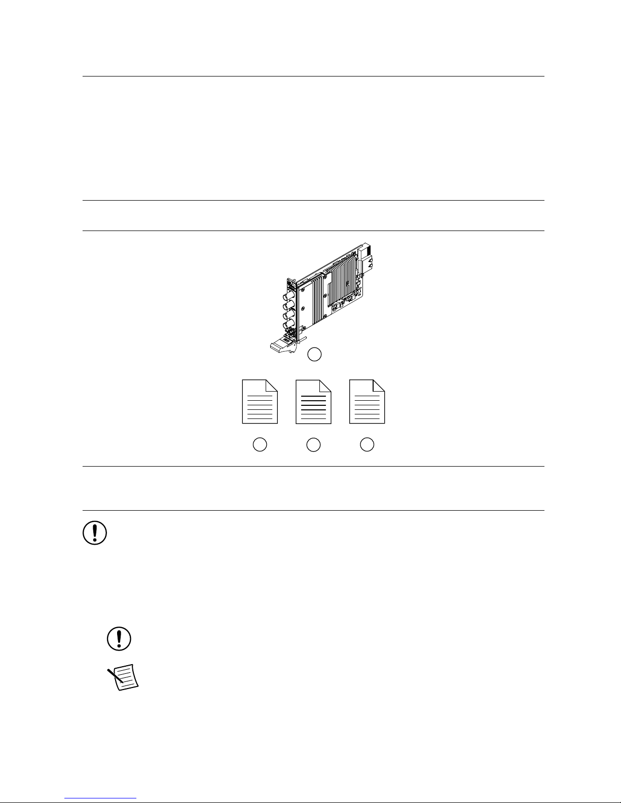
Refer to the following figure to identify the contents of the PXIe-5160/5162 kit.
1
42
3
1. PXIe-5160 or PXIe-5162
2. PXIe-5160 or PXIe-5162 Safety, Environmental,
and Regulatory Information
3. PXIe-5160/5162 Getting Started Guide (this
document)
4. Maintain Forced-Air Cooling Note to Users
Notice To prevent electrostatic discharge (ESD) from damaging the module,
ground yourself using a grounding strap or by holding a grounded object, such as
your computer chassis.
1. Touch the antistatic package to a metal part of the computer chassis.
2. Remove the module from the package and inspect it for loose components or other signs
of damage.
Notice Never touch the exposed pins of connectors.
Note Do not install a module if it appears damaged in any way.
3. Unpack any other items and documentation from the kit.
Store the module in the antistatic package when the module is not in use.
2 | ni.com | PXIe-5160/5162 Getting Started Guide
Page 3

Other Equipment
There are several required items not included in your device kit that you need to operate the
PXIe-5160/5162. Your application may require additional items not included in your kit to
install or operate your device.
Required Items
• A PXI Express chassis and chassis documentation
• A PXI Controller or PC with a Device for PXI Remote Control system that meets the
system requirements specified in this guide and chassis documentation
Optional Items
• PXI Slot Blocker Kit, 5 slot blockers (NI part number 199198-01)
• PXI Filler Panel Kit, 17 filler panels (NI part number 778646-01)
• BNC-to-BNC cable, 50 Ω, 1 m (NI part number 781887-01)
• Oscilloscope probe compensator, SMB (NI part number 786983-01)
• Probes—refer to the following table for several options compatible with the
PXIe-5160/5162.
Table 1. Probe Options for the PXIe-5160/5162
Model NI Part Number Description
CP400X 784254-01 400 MHz, 2 m, 10X cable divider probe
CP500X 784253-01 500 MHz, 1.2 m, 10X cable divider probe
NI 5191 781785-01 800 MHz differential active probe
SA1000X 784255-01 1 GHz single-ended active probe
SA1500X 784256-01 1.5 GHz single-ended active probe
SA2500X 784257-01 2.5 GHz single-ended active probe
SP200B 780284-01 1x or 10x passive probe, 200 MHz
SP500C 783630-01 100x passive probe, 500 MHz
SP500X 783629-01 10x passive probe, 500 MHz
CC0550X 786846-01 5 A RMS, 50 MHz current probe
CC05120X 786847-01 5 A RMS, 120 MHz current probe
CC5002X 786848-01 500 A RMS, 2 MHz current probe
CC15010X 786849-01 150 A RMS, 10 MHz current probe
PXIe-5160/5162 Getting Started Guide | © National Instruments | 3
Page 4

Table 1. Probe Options for the PXIe-5160/5162 (Continued)
Model NI Part Number Description
CC3050X 785561-01 30 A RMS, 50 MHz current probe
CC30100X 785562-01 30 A RMS, 100 MHz current probe
Visit ni.com for more information about these additional items.
Preparing the Environment
Ensure that the environment in which you are using the PXIe-5160/5162 meets the following
specifications.
Temperature
Operating 0 °C to 45 °C
Storage -40 °C to 71 °C
Humidity
Operating 10% to 90%, noncondensing
Storage 5% to 95%, noncondensing
Pollution Degree 2
Maximum altitude 2,000 m (800 mbar) (at 25 °C ambient temperature)
Indoor use only.
Installing the Software
You must be an Administrator to install NI software on your computer.
1. Install an ADE, such as LabVIEW or LabWindows™/CVI™.
2. Visit ni.com/downloads/drivers and search for NI-SCOPE.
3. Download the latest version of NI-SCOPE, extract the downloaded files, and run the
executable (.exe) file.
Driver support for the PXIe-5160/5162 was first available in NI-SCOPE 4.1.
4. Follow the instructions in the installation prompts.
Note Windows users may see access and security messages during
installation. Accept the prompts to complete the installation.
5. When the installer completes, select Restart in the dialog box that prompts you to restart,
shut down, or restart later.
4 | ni.com | PXIe-5160/5162 Getting Started Guide
Page 5

Installing the PXIe-5160/5162
Notice To prevent damage to the PXIe-5160/5162 caused by ESD or
contamination, handle the module using the edges or the metal bracket.
1. Ensure the AC power source is connected to the chassis before installing the module.
The AC power cord grounds the chassis and protects it from electrical damage while you
install the module.
2. Power off the chassis.
3. Inspect the slot pins on the chassis backplane for any bends or damage prior to
installation. Do not install a module if the backplane is damaged.
4. Remove the black plastic covers from all the captive screws on the module front panel.
5. Identify a supported slot in the chassis. The following figure shows the symbols that
indicate the slot types.
Figure 1. Chassis Compatibility Symbols
NI PXIe-1062Q
1
2 3
4
5
1. PXI Express System Controller Slot
2. PXI Peripheral Slot
3. PXI Express Hybrid Peripheral Slot
4. PXI Express System Timing Slot
5. PXI Express Peripheral Slot
PXIe-5160/5162 modules can be placed in PXI Express peripheral slots, PXI Express
hybrid peripheral slots, or PXI Express system timing slots.
6. Touch any metal part of the chassis to discharge static electricity.
7. Ensure that the ejector handle is in the downward (unlatched) position.
8. Place the module edges into the module guides at the top and bottom of the chassis. Slide
the module into the slot until it is fully inserted.
PXIe-5160/5162 Getting Started Guide | © National Instruments | 5
Page 6
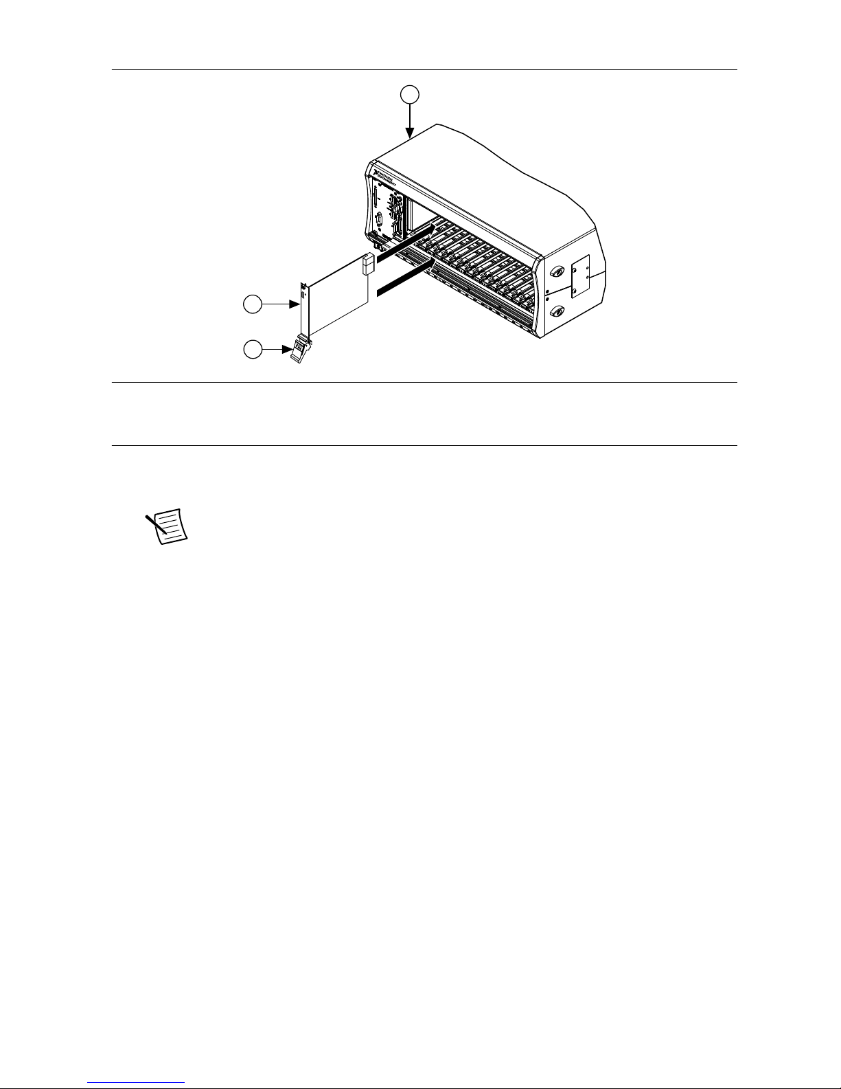
Figure 2. Module Installation
2
3
NI PXIe-1075
1
1. Chassis
2. Hardware Module
3. Ejector Handle in Downward (Unlatched) Position
9. Latch the module in place by pulling up on the ejector handle.
10. Secure the module front panel to the chassis using the front-panel mounting screws.
Note Tightening the top and bottom mounting screws increases mechanical
stability and also electrically connects the front panel to the chassis, which can
improve the signal quality and electromagnetic performance.
11. Cover all empty slots using EMC filler panels or fill using slot blockers to maximize
cooling air flow, depending on your application.
12. Power on the chassis.
6 | ni.com | PXIe-5160/5162 Getting Started Guide
Page 7

PXIe-5160/5162 Front Panels
CH 0
50Ω: 5 Vpk MAX
1MΩ: 42 Vpk MAX
CH 1
TRIG
CLK
IN
PFI
0
1OUT
NI PXIe-5160
500 MHz Oscilloscope
CH 0
50Ω: 5 Vpk MAX
1MΩ: 42 Vpk MAX
CH 1
CH 2
CLK
IN
PFI
0
1OUT
NI PXIe-5160
500 MHz Oscilloscope
CH 3
Note PXIe-5160 shown.
Table 2. PXIe-5160/5162 Signal Descriptions
Signal Connector Type Description
CH 0, CH 1
BNC
Analog input connection; digitizes data and triggers
acquisitions
CH 2, CH 3 Additional analog input connections on the PXIe-5160/5162
(4 CH)
TRIG External analog trigger connection; signals on the TRIG
connector cannot be digitized; PXIe-5160/5162 (2 CH) only
PXIe-5160/5162 Getting Started Guide | © National Instruments | 7
Page 8

Table 2. PXIe-5160/5162 Signal Descriptions (Continued)
Signal Connector Type Description
CLK IN
SMB
Imports an external Reference Clock or Sample Clock to the
device
CLK OUT Exports the Reference Clock from the device
PFI 0 PFI line for digital trigger input/output
PFI 1 PFI line for digital trigger input/output and probe
compensation; no subsample trigger accuracy
Configuring the PXIe-5160/5162 in MAX
Use Measurement & Automation Explorer (MAX) to configure your NI hardware. MAX
informs other programs about which NI hardware products are in the system and how they are
configured. MAX is automatically installed with NI-SCOPE.
1. Launch MAX.
2. In the configuration tree, expand Devices and Interfaces to see the list of installed NI
hardware.
Installed modules appear under the name of their associated chassis.
3. Expand your Chassis tree item.
MAX lists all modules installed in the chassis. Your default names may vary.
Note If you do not see your module listed, press <F5> to refresh the list of
installed modules. If the module is still not listed, power off the system, ensure
the module is correctly installed, and restart.
4. Record the identifier MAX assigns to the hardware. Use this identifier when
programming the PXIe-5160/5162.
5. Self-test the hardware by selecting the item in the configuration tree and clicking Self-
Test in the MAX toolbar.
The MAX self-test performs a basic verification of hardware resources.
8 | ni.com | PXIe-5160/5162 Getting Started Guide
Page 9

PXIe-5160/5162 Self-Calibration
To eliminate errors caused by changing temperatures, NI-SCOPE provides a highly repeatable
self-calibration function.
For the PXIe-5160/5162, self-calibration yields the following benefits:
• Corrects for DC gain and offset errors within the digitizer by comparison to a precision,
high-stability internal voltage reference for all ranges, input impedance paths (50 Ω and
1 MΩ), and filter paths.
• Calibrates trigger level offset and gain.
• Calibrates trigger timing, as well as the time-to-digital conversion circuitry to ensure
accurate trigger timing and time-stamping.
• Calibrates gain, offset, and phase for interleaved ADC modes, reducing ADC interleaving
errors in time-interleaved sampling modes.
• Calibrates the phase DAC used to adjust the phase of the sample clock.
Self-calibration takes approximately two minutes to complete.
Running Self-Calibration
Running self-calibration enables the PXIe-5160/5162 to yield full performance over its
operating temperature range and two-year external calibration cycle.
Before running self-calibration:
• Warm up the PXIe-5160/5162 for at least 15 minutes
• When possible, disconnect the inputs
1
PXIe-5160/5162 modules are externally calibrated at the factory, but for optimal performance,
use self-calibration in any of the following situations:
• When the module is placed in a new system
• When the temperature changes more than ±3 °C from the previous self-calibration
• Once 90 days have elapsed since the previous self-calibration
Note Unless temperature variations are a serious problem in your application, self-
calibration is not recommended more than once per day.
Tip You can use the nodes on the NI-SCOPE External Calibration palette to
programmatically return the date and module temperature of the previous selfcalibration. You can also view this information by selecting the device in MAX.
Self-calibrate the PXIe-5160/5162 programmatically in NI-SCOPE or on demand in MAX.
Option Description
NI-SCOPE Use the Self Calibrate node to self-calibrate the module.
1
If high-voltage, high-frequency signals are present during self-calibration, the calibration results
may be adversely affected or the calibration may fail with an error.
PXIe-5160/5162 Getting Started Guide | © National Instruments | 9
Page 10

Option Description
MAX Select the device in the Devices and Interfaces menu and click the Self-
Calibrate button.
When the two-year external calibration interval expires, an external calibration is required to
ensure performance within specifications over the subsequent two years.
First Measurements
Making a Measurement with InstrumentStudio
1. Connect CH 0 to an input signal.
2. Launch InstrumentStudio at Start»National Instruments.
3.
In the instrument header menu in the upper-right corner of the panel (
), add the
PXIe-5160/5162 to the large panel with Add/Remove Devices.
4. Click Auto to automatically configure device settings for the detected signal.
5. If the soft front panel is not already running, click Run/Stop.
6. Add oscilloscope measurements to the channel by selecting Add/Remove in the
measurement table of the oscilloscope.
For more information on the measurements available for oscilloscopes in InstrumentStudio,
refer to the InstrumentStudio Manual at ni.com/manuals.
Making a Measurement with LabVIEW
1. Launch LabVIEW.
2. Select Help»Find Examples.
3. Open the example VI that you want to use by selecting Hardware Input and Output»
Modular Instruments»NI-SCOPE (High-Speed Digitizers).
Tip If you are not sure which example to run, use the Quick Start VI, which is
found under Hardware Input and Output»Modular Instruments»NI-
SCOPE (High-Speed Digitizers)»Demos»niScope EX Quick Start.vi.
4. Follow any setup instructions in the VI and specify any desired settings.
5. Click Run to run the example program.
10 | ni.com | PXIe-5160/5162 Getting Started Guide
Page 11

PXIe-5160/5162 Compensating Passive Probes
Compensating passive probes increases the accuracy of your measurements by matching the
capacitance of your probe to the capacitance of a particular oscilloscope input channel.
Before beginning this procedure, complete the following:
• Set up your oscilloscope in a compatible chassis;
• Install a version of NI-SCOPE compatible with your oscilloscope on your system; and
• Configure a panel and layout in InstrumentStudio to include your oscilloscope.
Note For more information on using InstrumentStudio, refer to the
InstrumentStudio Manual at ni.com/manuals.
The following equipment is required for this procedure:
If using the Oscilloscope Probe
Compensator
• Oscilloscope Probe Compensator (NI part number
786983-01)
If connecting the probe directly to
the oscilloscope PFI
• A 50 Ω SMB (f)-to-BNC (f) cable, such as the
SMB-100 (NI part number 781449-01)
• A probe tip–to-BNC (m) adapter
The PXIe-5160/5162 can output a 1 kHz square wave that you can use to compensate passive
probes.
To compensate a passive probe, complete the following steps:
1. Connect the BNC end of the probe to an input channel of your oscilloscope.
2. Depending on your connection method, connect the probe tip to the oscilloscope:
• Oscilloscope Probe Compensator
1. Connect the SMB end of the Oscilloscope Probe Compensator to the PFI
connector of the oscilloscope that generates the probe compensation signal.
2. Connect the ground clip of the probe to the ground terminal.
3. Contact the tip of the probe to the square wave terminal.
• Direct connection to PFI
1. Connect the SMB end of the SMB (f)-to-BNC (f) cable to the PFI connector of
the oscilloscope that generates the probe compensation signal.
2. Attach the BNC adapter to the tip of the probe.
3. Connect the probe tip via the BNC adapter to the BNC end of the cable.
3. Enable the probe compensation signal:
Option Description
InstrumentStudio
In the instrument header menu ( ) in the upper-right corner of
the panel, select Probe Compensation»Enabled.
PXIe-5160/5162 Getting Started Guide | © National Instruments | 11
Page 12

Option Description
NI-SCOPE Call Probe Compensation Signal Start.
4. In InstrumentStudio, configure the settings of the input channel to which you connected
the probe.
a) Set the channel to On to display the signal.
b) Set the Input impedance of the channel to 1 MΩ.
c) Match the Probe attenuation setting to the setting on your probe.
5. Adjust the vertical range on the input channel until the signal starts to clip and then
increase the vertical range by one step so that it no longer clips.
This process ensures you are using the maximum dynamic range of the ADC.
6. Examine the digitized signal and adjust the tunable capacitor on the probe.
The probe is correctly compensated when the waveform appears as square as possible:
Probe Adjustment Signal Probe Adjustment Signal Probe Adjustment Signal
Compensated Correctly Undercompensated Overcompensated
Proper Amplitude of a
1 MHz Test Signal
Reduced Amplitude of a
1 MHz Test Signal
Increased Amplitude of a
1 MHz Test Signal
Once compensated, the probe conveys signals to the input channel accurately, without
artificially attenuating or amplifying frequency components of the signal.
Tip For the most accurate measurements:
• Compensate probes for each channel of the oscilloscope;
• Use a compensated probe only with the channel you used to compensate it; and
• Compensate your probes frequently.
12 | ni.com | PXIe-5160/5162 Getting Started Guide
Page 13

Programming the PXIe-5160/5162
You can acquire data interactively using InstrumentStudio, or you can use the NI-SCOPE
instrument driver to program your device in the supported ADE of your choice.
PXIe-5160/5162 Getting Started Guide | © National Instruments | 13
Page 14

Table 3. PXIe-5160/5162 Programming Options
Application Location Description
InstrumentStudio
Note InstrumentStudio is
supported only on 64-bit
systems. If you are using a
32-bit system, use your
driver's specific soft front
panel instead of
InstrumentStudio.
InstrumentStudio is automatically
installed when you install the
NI-SCOPE driver. You can access
InstrumentStudio in one of the
following ways:
• From the Windows start menu,
select National Instruments»
[Driver] Soft Front Panel. This
launches InstrumentStudio and
runs a soft front panel populated
with NI-SCOPE devices.
• From the Windows Start menu,
select National Instruments»
InstrumentStudio [year]. This
launches InstrumentStudio and
runs a soft front panel populated
with devices detected on your
system.
• From Measurement & Automation
Explorer (MAX), select a device
and then click Test Panels.... This
launches InstrumentStudio and
runs a soft front panel for the
device you selected.
When you install NI-SCOPE
on a 64-bit system, you can
monitor, control, and record
measurements from supported
devices using
InstrumentStudio.
InstrumentStudio is a
software-based front panel
application that allows you to
perform interactive
measurements on several
different device types in a
single program.
14 | ni.com | PXIe-5160/5162 Getting Started Guide
Page 15

Table 3. PXIe-5160/5162 Programming Options (Continued)
Application Location Description
NI-SCOPE
Instrument Driver
LabVIEW—Available on the LabVIEW
Functions palette at Measurement I/O»
NI-SCOPE.
The NI-SCOPE API
configures and operates the
device hardware and provides
customizable acquisition,
control, analysis, and
measurement options using
LabVIEW VIs or
LabWindows/CVI functions.
C or LabWindows/CVI—Available at
Program Files»IVI Foundation»IVI»
Drivers»niScope.
Microsoft Visual C/C++, .NET—Use
examples located in the file directory
Users\Public\Public
Documents\National
Instruments\NI–SCOPE
\examples.
You can modify an NI-SCOPE
C example to create an
application with Microsoft
Visual C/C++, or modify
a .NET example to create an
application with Visual
Basic .NET or Visual C#.
Copy an NI-SCOPE example
to copy required project
settings for include paths and
library files. Alternatively,
refer to the Creating an
Application section of the NI
High-Speed Digitizers Help to
manually add all required
include and library files to
your project.
NI-SCOPE Examples
Examples demonstrate the functionality of the device and serve as programming models and
building blocks for your own applications.
The NI Example Finder is a utility available for some ADEs that organizes examples into
categories and allows you to easily browse and search installed examples. You can see
descriptions and compatible hardware models for each example, or see all the examples
compatible with one particular hardware model.
To locate examples, refer to the following table:
PXIe-5160/5162 Getting Started Guide | © National Instruments | 15
Page 16

Application Development
Environment (ADE)
Locating Examples
LabVIEW or
LabWindows/CVI
Locate examples with the NI Example Finder. Within
LabVIEW or LabWindows/CVI, select Help»Find
Examples, and navigate to Hardware Input and Output»
Modular Instruments.
Visual C/C++ or Visual Basic Locate examples in the file directory Users\Public
\Public Documents\National Instruments\NI–
SCOPE\examples.
Visual C# or Visual
Basic .NET
Troubleshooting
What Should I Do if the PXIe-5160/5162 Doesn't
Appear in MAX?
1. In the MAX configuration tree, expand Devices and Interfaces.
2. Expand the Chassis tree to see the list of installed hardware, and press <F5> to refresh
the list.
3. If the module is still not listed, power off the system, ensure that all hardware is correctly
installed, and restart the system.
4. Navigate to the Device Manager.
Operating System Description
Windows 10/8.1 Right-click the Start button, and select Device Manager.
Windows 7 Select Start»Control Panel»Device Manager.
5. Verify the PXIe-5160/5162 appears in the Device Manager.
a) Under an NI entry, confirm that a PXIe-5160/5162 entry appears.
Note If you are using a PC with a device for PXI remote control system,
under System Devices, also confirm that no error conditions appear for the
PCI-to-PCI Bridge.
b) If error conditions appear, reinstall NI-SCOPE and the PXIe-5160/5162.
What Should I Do if the PXIe-5160/5162 Fails the SelfTest?
1. Restart the system.
2. Launch MAX, and perform the self-test again.
3. Power off the chassis.
4. Reinstall the failed module in a different slot.
16 | ni.com | PXIe-5160/5162 Getting Started Guide
Page 17

5. Power on the chassis.
6. Perform the self-test again.
Thermal Shutdown Error
If you receive an over-temperature or thermal shutdown error and your device shuts down,
complete the following steps to re-enable your device:
1. Power off the computer or chassis that contains the device.
2. Reinstall the device and make any necessary adjustments to make sure that the device is
effectively cooled.
3. Power on the computer or chassis.
Note The thermal shutdown error is reported until the device has cooled to an
acceptable operating temperature and has been successfully reset.
For more information about cooling the device, refer to the Maintain Forced-Air Cooling
Note to Users included in your kit.
Where To Go Next
Refer to the following figure for information about other product tasks and associated
resources for those tasks.
DISCOVER
CREATELEARNEXPLORE
Getting Started with
LabWindows/CVI
Getting Started with
LabVIEW
Located using the NI Example Finder
500 MHz Oscilloscope
NI PXIe-5160
Located online at ni.com/manuals
Services
ni.com/services
Support
ni.com/support
more about your products through ni.com.
Updates
ni.com/updates
NI Oscilloscopes
ni.com/digitizers
the application development
environment (ADE)
for your application.
about hardware features
or review device
specifications.
custom applications with
an application programming
interface (API).
NI High-Speed
Digitizers Help
PXIe-5160
Specifications
PXIe-5162
Specifications
NI High-Speed
Digitizers Help
InstrumentStudio
NI-SCOPE Examples
NI-SCOPE Instrument Driver
PXIe-5160/5162 Getting Started Guide | © National Instruments | 17
Page 18

Worldwide Support and Services
The NI website is your complete resource for technical support. At ni.com/support, you have
access to everything from troubleshooting and application development self-help resources to
email and phone assistance from NI Application Engineers.
Visit ni.com/services for information about the services NI offers.
Visit ni.com/register to register your NI product. Product registration facilitates technical
support and ensures that you receive important information updates from NI.
NI corporate headquarters is located at 11500 North Mopac Expressway, Austin, Texas,
78759-3504. NI also has offices located around the world. For support in the United States,
create your service request at ni.com/support or dial 1 866 ASK MYNI (275 6964). For
support outside the United States, visit the Worldwide Offices section of ni.com/niglobal to
access the branch office websites, which provide up-to-date contact information.
Information is subject to change without notice. Refer to the NI Trademarks and Logo Guidelines at ni.com/trademarks for
information on NI trademarks. Other product and company names mentioned herein are trademarks or trade names of their
respective companies. For patents covering NI products/technology, refer to the appropriate location: Help»Patents in your
software, the patents.txt file on your media, or the National Instruments Patent Notice at ni.com/patents. You can find
information about end-user license agreements (EULAs) and third-party legal notices in the readme file for your NI product. Refer
to the Export Compliance Information at ni.com/legal/export-compliance for the NI global trade compliance policy and how
to obtain relevant HTS codes, ECCNs, and other import/export data. NI MAKES NO EXPRESS OR IMPLIED WARRANTIES AS
TO THE ACCURACY OF THE INFORMATION CONTAINED HEREIN AND SHALL NOT BE LIABLE FOR ANY ERRORS. U.S.
Government Customers: The data contained in this manual was developed at private expense and is subject to the applicable
limited rights and restricted data rights as set forth in FAR 52.227-14, DFAR 252.227-7014, and DFAR 252.227-7015.
© 2013—2019 National Instruments. All rights reserved.
375440B-01 February 14, 2019
 Loading...