

Page 1
INSTALLATION GUIDE AND SPECIFICATIONS
PXIe-4844
This document includes the installation instructions and specifications for the National
Instruments PXIe-4844 Optical Sensor Interrogator (OSI) module. The PXIe-4844 is a dual-slot,
3U PXI Express data acquisition module for fiber Bragg grating (FBG) optical sensors. The
PXIe-4844 provides four optical channels that are simultaneously sampled at 10 Hz, and is
expandable to eight or 16 channels with an external optical multiplexer.
FBG fiber optic sensing provides many benefits over conventional electrical sensing because it
is nonconductive, electrically passive, and immune to EMI. FBG technology also enables
measurements over long distances without loss of signal accuracy and provides the ability to
daisy-chain dozens of sensors along a single optical fiber. The PXIe-4844 requires no calibration
as it continuously adjusts its measurements using an on-board NIST traceable wavelength
reference.
Caution This icon denotes a caution, which advises you of precautions to take to
avoid injury, data loss, or a system crash.
Safety Guidelines
Follow these guidelines when installing and using the PXIe-4844.
Caution Do not enable the laser unless an optical connector or LC/APC connector
cover is connected to the LC/APC connector port. The laser enables when the device
receives power.
Caution Never look into the end of an optical cable attached to an optical output
when the device is powered on. The laser radiation is not visible to the human eye,
but it can seriously damage your eyesight.
Caution Do not modify the PXIe-4844 module. This may result in hazardous
radiation exposure from the laser source.
Caution The protection provided by the PXIe-4844 can be impaired if it is used in
a manner not described in this document.
Page 2
Electromagnetic Compatibility Guidelines
This product was tested and complies with the regulatory requirements and limits for
electromagnetic compatibility (EMC) as stated in the product specifications. These requirements
and limits are designed to provide reasonable protection against harmful interference when the
product is operated in its intended operational electromagnetic environment.
This product is intended for use in industrial locations. There is no guarantee that harmful
interference will not occur in a particular installation, when the product is connected to a test
object, or if the product is used in residential areas. To minimize the potential for the product to
cause interference to radio and television reception or to experience unacceptable performance
degradation, install and use this product in strict accordance with the instructions in the product
documentation.
Furthermore, any changes or modifications to the product not expressly approved by National
Instruments could void your authority to operate it under your local regulatory rules.
Caution To ensure the specified EMC performance, operate this product only with
shielded cables and accessories.
Caution To ensure the specified EMC performance when using the AUX port,
install a snap-on, ferrite bead (National Instruments part number 781233-01) in
accordance with the product installation instructions.
Unpacking
The product shipping kit includes the PXIe-4844 hardware module and the NI-OSI driver
software DVD. The PXIe-4844 module ships in an antistatic package to prevent damage from
electrostatic discharge (ESD), and the package is inside a hard-shelled plastic case. Before
removing the hardware module from the antistatic package, touch the antistatic package to a
metal part of your computer chassis to discharge any static electricity. Ground yourself using a
grounding strap or by touching a grounded metal object.
Remove the hardware module from the package and inspect it for loose components or any signs
of damage. Contact NI if the hardware module appears damaged in any way. Do not install
a damaged module into your system. Store the module in the antistatic package and the
hard-shelled plastic case when not in use.
Note When transporting the PXIe-4844 over long distances, remove the module
from the chassis and place the module in the original antistatic package and
hard-shelled plastic case.
2 | ni.com | PXIe-4844 Installation Guide and Specifications
Page 3
What You Need to Get Started
LabVIEW 2009 (32-bit), 2010 (32-bit), 2011 (32-bit), 2012 (32-bit), 2013 (32-bit),
2014 (32-bit), 2015 (32-bit), or 2016 (32-bit)
PXI Express chassis with
– controller, or
– MXI-Express (card or built-in)
FBG sensors
Multiplexer for additional channels (optional)
Installing the NI-OSI Driver Software
Install the NI-OSI driver software on the host computer before installing the PXIe-4844 module.
Refer to
directory, for software installation instructions, LabVIEW compatibility information, and
system requirements.
readme_OSI.html, located in the National Instruments\OSI Explorer
Installing the PXIe-4844
This section contains installation instructions for the PXIe-4844. Refer to your PXI Express
chassis user manual for chassis instructions and warnings.
1. Plug in your chassis before installing the PXIe-4844. The power cord grounds the chassis
and protects it from electrical damage while you install the module.
2. Make sure the chassis power switch is turned off.
Caution To protect both yourself and the chassis from electrical hazards, leave the
chassis powered off until you finish installing the PXIe-4844 module.
3. Touch a metal part on the chassis to discharge any static electricity that might be on your
clothes or body.
PXIe-4844 Installation Guide and Specifications | © National Instruments | 3
Page 4
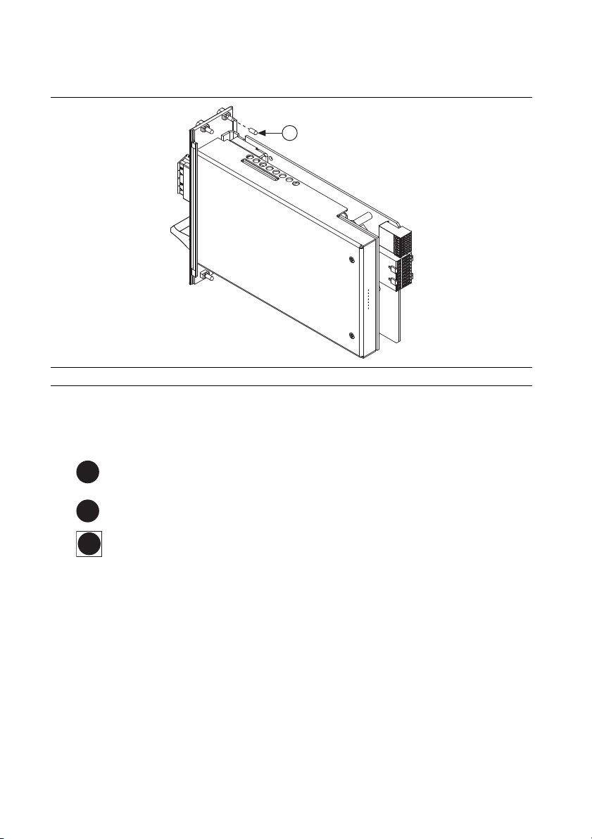
4. Remove the protective plastic covers from the four front panel mounting screws on the
1
7
H
module, as shown in Figure 1.
Figure 1. Removing Protective Screw Caps
1 Protective Screw Cap (4x)
5. Make sure the PXIe-4844 injector/ejector handle is in its downward position.
6. Identify two side-by-side empty chassis slots, except for a PXI Express System Controller
slot. Of these two slots, the left-most slot must be one of the following PXI Express slots:
8
PXI Express Peripheral Slot—a PXI Express slot marked with a solid circle
containing the slot number.
PXI Express Hybrid Peripheral Slot—a PXI Express hybrid slot marked with the
letter “H” and a solid circle containing the slot number.
10
PXI Express System Timing Slot—a PXI Express timing slot marked with a
square surrounding a solid circle containing the slot number.
7. Remove the filler panels covering the selected slots.
8. Align the PXIe-4844 with the card guides on the top and bottom of the selected slots.
4 | ni.com | PXIe-4844 Installation Guide and Specifications
Page 5

9. Hold the injector/ejector handle down as you slowly slide the module into the chassis until
the handle catches on the injector/ejector rail, as shown in Figure 2.
Caution When installing the module, make sure both edges are positioned inside
the guides and that the module components do not come into contact with adjacent
modules.
Figure 2. Sliding the PXIe-4844 into the Chassis
1
NI PXIe-1073
5
4
2
3
1 PXI Express Chassis
2 Injector/Ejector Rail
3 Injector/Ejector Handle
4 PXIe-4844
5 Front Panel Mounting Screw (4x)
10. Raise the injector/ejector handle to latch the module into the chassis. The front panel of the
PXIe-4844 should be even with the front panel of the chassis.
11. Tighten the four front panel mounting screws to 0.31 N · m (2.7 lb · in.) on the top and
bottom of the module front panel to secure the PXIe-4844 to the chassis.
12. Power on the chassis.
PXIe-4844 Installation Guide and Specifications | © National Instruments | 5
Page 6

Removing the PXIe-4844 from the PXIe Chassis
To remove the PXIe-4844 from the PXI Express chassis, complete the following steps:
1. Power off the chassis.
2. Remove any cables or sensors attached to the PXIe-4844.
3. Loosen the four front panel mounting screws on the module.
4. Press the injector/ejector handle down.
5. Slide the module out of the chassis.
6. Place the PXIe-4844 in its original antistatic bag. Store the module within its hard-shelled
plastic case.
Connecting Sensors
The PXIe-4844 has four simplex singlemode LC/APC connector ports to connect sensors. If
your sensor does not have an LC/APC connector, you need an adapter to connect the sensor to
the LC/APC connector port.
Caution Connecting damaged or dirty sensors to the module can damage the
LC/APC connector ports on the module. Always clean optical connectors before
connecting to the module.
Caution Never force an optical connector into an LC/APC connector port.
A ferrule may break and damage the module.
6 | ni.com | PXIe-4844 Installation Guide and Specifications
Page 7

Connect the LC/APC connector on the sensor to an available LC/APC connector port on the
module.
Figure 3. PXIe-4844 Channels and AUX Port
NI PXIe-4844
4 Channel Optical Sensor Interrogator
INPUT
CH 0
CH 1
CH 2
CH 3
APC
Connectors
AUX
1 Four LC/APC Connector ports 2 AUX port
1
2
Caution When connecting any accessory to the AUX port, install a ferrite bead
(NI part number 781233-01) on the connecting cable as close to the AUX port as
possible.
Note The AUX port is an 8-pin mini-DIN connector you can use to connect
third-party multiplexers to the PXIe-4844.
Cleaning Sensors
To clean the optical sensors, use a ferrule cleaner or follow the standard guidelines:
1. Fold a lint-free wipe into a compress.
2. Moisten the compress with isopropyl alcohol.
3. Remove the protective cover from the sensor connector.
4. Press the connector endface firmly to the moistened section of the compress, then forcefully
wipe the connector with a twisting motion toward the edge of the compress, finishing in a
clean, dry section of the compress. Do not reuse dirty sections of the compress.
5. Discard the used compress.
PXIe-4844 Installation Guide and Specifications | © National Instruments | 7
Page 8

Calibration
The PXIe-4844 has continuous on-board calibration using epoxy-free Telcordia-qualified
optical referencing components and continuous on-board NIST traceable wavelength reference
components to ensure that sensor wavelength measurements remain within specifications over
the life of the product.
Using the NI-OSI Explorer and LabVIEW VIs
The NI-OSI driver software installs the NI-OSI Explorer and the NI-OSI LabVIEW VIs. Use the
NI-OSI Explorer to identify and configure the optical sensors connected to the PXIe-4844. Use
the Optical Measurement VIs in LabVIEW to perform optical sensing measurements. To get
started:
1. Select Start»All Programs»National Instruments»NI-OSI Explorer»NI-OSI
Explorer.
2. Read the Welcome dialog. Follow the links provided for more information on configuring
sensors and performing measurements.
Specifications
The following specifications are typical for the PXIe-4844 operating at 25 °C unless otherwise
noted.
Bus Interface
Form factor ....................................................... x4 PXI Express, v1.0 compliant
Laser
Type................................................................... Fiber laser
Class.................................................................. 1
Output power (continuous wave)
Min............................................................ 0.06 mW
Max ........................................................... 0.25 mW
Beam diameter .................................................. 9 mm (0.35 in.)
Numerical aperture ........................................... 0.1
8 | ni.com | PXIe-4844 Installation Guide and Specifications
Page 9

Optical Input
Number of channels.......................................... 4
Wavelength range ............................................. 1510 nm to 1590 nm
Sample rate ....................................................... 10 Hz ± 0.1 Hz
Optical dynamic range...................................... 40 dB
FBG Wavelength Detection
Accuracy ........................................................... 1 pm
Stability (0 °C to 55 °C) ................................... 1 pm
Repeatability ..................................................... 1 pm
Physical Characteristics
If you need to clean the PXIe-4844, use a soft, non-metallic brush. Make sure that the device is
completely dry and free from contaminants before returning it to the PXI Express chassis.
Note For two-dimensional drawings and three-dimensional models of the
PXIe-4844 module and connectors, visit
module number.
Dimensions (without connectors)..................... 13.1 cm × 21.4 cm × 4.1 cm
Weight............................................................... 213 g (7.5 oz)
I/O connector .................................................... LC/APC
Slot requirements .............................................. Two side-by-side chassis slots, other than a
Slot compatibility ............................................. x4, x8, and x16 PXI Express or
ni.com/dimensions and search by
(5.1 in. × 8.4 in. × 1.6 in.)
PXI Express System Controller slot. The
left-most slot must be a PXI Express,
PXI Express Hybrid, or PXI Express System
Timing slot.
PXI Express Hybrid slots
Safety Standards
This product meets the requirements of the following standards of safety for electrical equipment
for measurement, control, and laboratory use:
• IEC 61010-1, EN 61010-1
• UL 61010-1, CSA C22.2 No. 61010-1
Note For UL and other safety certifications, refer to the product label or the Online
Product Certification section.
PXIe-4844 Installation Guide and Specifications | © National Instruments | 9
Page 10

Electromagnetic Compatibility
This product meets the requirements of the following EMC standards for electrical equipment
for measurement, control, and laboratory use:
• EN 63126-1 (IEC 61326-1): Class A emissions, Basic immunity
• EN 55011 (CISPR 11): Group 1, Class A emissions
• AS/NZS CISPR 11: Group 1, Class A emissions
• FCC 47 CFR Part 15B: Class A emissions
• ICES-001: Class A emissions
Note For EMC declarations and certifications, refer to the Online Product
Certification section.
Laser Compliance
This product meets the requirements of the following laser compliance standards for electrical
equipment for measurement, control, and laboratory use:
• IEC 60825-1, ED 2.0, 2007-03; US CDRH 21 CFR Subchapter J
CE Compliance
This product meets the essential requirements of applicable European Directives as follows:
• 2014/35/EU; Low-Voltage Directive (safety)
• 2014/30/EU; Electromagnetic Compatibility Directive (EMC)
Online Product Certification
To obtain product certifications and the Declaration of Conformity (DoC) for this product, visit
ni.com/certification, search by module number or product line, and click the
appropriate link in the Certification column.
Shock and Vibration
Mechanical shock
Operating
(IEC 60068-2-7 Annex A,
section A.4, Table A.1) ............................. 15 g peak, half-sine, 11 ms pulse
Non-operating (IEC 60068-2-7) ...............25 g peak, half-sine, 11 ms pulse
Random vibration
Operating (ETSI 300 019-2-3).................. 0.15 g
Non-operating (IEC 60068-2-64) .............0.8 g
10 | ni.com | PXIe-4844 Installation Guide and Specifications
, 5 Hz to 100 Hz
rms
, 10 Hz to 150 Hz
rms
Page 11

Environmental
⬉ᄤֵᙃѻક∵ᶧࠊㅵ⧚ࡲ⊩ ˄Ё
RoHS
˅
Ёᅶ᠋
National Instruments
ヺড়Ё⬉ᄤֵᙃѻકЁ䰤ࠊՓ⫼ᶤѯ᳝ᆇ⠽䋼ᣛҸ
(RoHS)
DŽ݇Ѣ
National InstrumentsЁRoHS
ড়㾘ᗻֵᙃˈ䇋ⱏᔩ
ni.com/
environment/rohs_china
DŽ
(For information about China RoHS compliance,
go to
ni.com/environment/rohs_china
.)
This device is intended for indoor use only.
Caution Do not exceed the operating temperature, even when using the module in
a chassis with a higher temperature range.
Operating temperature
(IEC 60068-2-1, IEC 60068-2-2) ..................... 0 °C to 55 °C
Storage temperature
(IEC 60068-2-1, IEC 60068-2-2) ..................... -40 °C to 70 °C
Operating humidity (IEC 60068-2-56) ............. 10% to 90%, noncondensing
Storage humidity (IEC 60068-2-56)................. 5% to 95%, noncondensing
Maximum altitude............................................. 2,000 m
Environmental Management
NI is committed to designing and manufacturing products in an environmentally responsible
manner. NI recognizes that eliminating certain hazardous substances from our products is
beneficial to the environment and to NI customers.
For additional environmental information, refer to the Minimize Our Environmental Impact web
ni.com/environment. This page contains the environmental regulations and
page at
directives with which NI complies, as well as other environmental information not included in
this document.
Waste Electrical and Electronic Equipment (WEEE)
EU Customers At the end of the product life cycle, all products must be sent to
a WEEE recycling center. For more information about WEEE recycling centers,
National Instruments WEEE initiatives, and compliance with WEEE Directive
2002/96/EC on Waste and Electronic Equipment, visit
.
weee
PXIe-4844 Installation Guide and Specifications | © National Instruments | 11
ni.com/environment/
Page 12

Worldwide Support and Services
The NI website is your complete resource for technical support. At ni.com/support you have
access to everything from troubleshooting and application development self-help resources to
email and phone assistance from NI Application Engineers.
ni.com/services for NI Factory Installation Services, repairs, extended warranty, and
Vis it
other services.
ni.com/register to register your NI product. Product registration facilitates technical
Vis it
support and ensures that you receive important information updates from NI.
A Declaration of Conformity (DoC) is our claim of compliance with the Council of the European
Communities using the manufacturer’s declaration of conformity. This system affords the user
protection for electromagnetic compatibility (EMC) and product safety. You can obtain the DoC
for your product by visiting
you can obtain the calibration certificate for your product at ni.com/calibration.
NI corporate headquarters is located at 11500 North Mopac Expressway, Austin, Texas,
78759-3504. NI also has offices located around the world. For telephone support in the United
States, create your service request at
For telephone support outside the United States, visit the Worldwide Offices section of
ni.com/niglobal to access the branch office websites, which provide up-to-date contact
information, support phone numbers, email addresses, and current events.
ni.com/certification. If your product supports calibration,
ni.com/support or dial 1 866 ASK MYNI (275 6964).
Refer to the NI Trademarks and Logo Guidelines at ni.com/trademarks for more information on NI trademarks. Other product and company
names mentioned herein are trademarks or trade names of their respective companies. For patents covering NI products/technology, refer to the
appropriate location: Help»Patents in your software, the patents.txt file on your media, or the National Instruments Patents Notice at
ni.com/patents. You can find information about end-user license agreements (EULAs) and third-party legal notices in the readme file for your
NI product. Refer to the Export Compliance Information at ni.com/legal/export-compliance for the NI global trade compliance policy
and how to obtain relevant HTS codes, ECCNs, and other import/export data. NI MAKES NO EXPRESS OR IMPLIED WARRANTIES AS TO THE
ACCURACY OF THE INFORMATION CONTAINED HEREIN AND SHALL NOT BE LIABLE FOR ANY ERRORS. U.S. Government Customers: The data
contained in this manual was developed at private expense and is subject to the applicable limited rights and restricted data rights as set forth in
FAR 52.227-14, DFAR 252.227-7014, and DFAR 252.227-7015.
© 2010–2017 National Instruments. All rights reserved.
375513C-01 Feb17
 Loading...