

Page 1

CALIBRATION PROCEDURE
PXIe-4309
32 Ch (8 ADC), 2 MS/s, 18 - 28 bit, Flexible Resolution PXI Analog Input
Module
This document contains the verification and adjustment procedure for the PXIe-4309 module.
Note To maintain forced air cooling in the PXI Express system, refer to the
Maintain Forced-Air Cooling Note to Users.
Contents
Software.................................................................................................................................... 1
Documentation.......................................................................................................................... 2
Test Equipment......................................................................................................................... 3
Test Conditions......................................................................................................................... 4
Initial Setup............................................................................................................................... 4
Self Calibration................................................................................................................. 4
Verification ............................................................................................................................... 5
DC Offset Accuracy ......................................................................................................... 6
DC Voltage Accuracy....................................................................................................... 9
Adjustment................................................................................................................................ 13
EEPROM Update ..................................................................................................................... 16
Reverification ........................................................................................................................... 17
Specifications............................................................................................................................ 17
Worldwide Support and Services ............................................................................................. 17
Software
Calibrating the PXIe-4309 requires the installation of NI-DAQmx on the calibration system.
Driver support for calibrating the PXIe-4309 was first available in NI-DAQmx 17.1. For the list
of devices supported by a specific release, refer to the NI-DAQmx Readme, available on the
version-specific download page or installation media.
You can download NI-DAQmx from
LabWindows™/CVI™, C/C++, C#, and Visual Basic .NET. When you install NI-DAQmx, you
only need to install support for the application software that you intend to use.
No other software is required to verify the operation of the TB-4309 (ST), TB-4309 (MT), or
CAL-4309.
ni.com/downloads. NI-DAQmx supports LabVIEW,
Page 2
Documentation
Consult the following documents for information about the PXIe-4309, NI-DAQmx, and your
application software. All documents are available on
software.
PXIe-4309 and TB-4309 (ST)/TB-4309 (MT) Getting Started Guide and Terminal Block
Specifications
NI-DAQmx driver software installation and hardware setup.
PXIe-4309 User Manual
PXIe-4309 usage and reference information.
PXIe-4309 Specifications
PXIe-4309 specifications and calibration interval.
NI-DAQmx Readme
Operating system and application software support in NI-DAQmx.
NI-DAQmx Help
Information about creating applications that use the NI-DAQmx driver.
ni.com, and help files install with the
LabVIEW Help
LabVIEW programming concepts and reference information about NI-DAQmx VIs and
functions.
NI-DAQmx C Reference Help
Reference information for NI-DAQmx C functions and NI-DAQmx C properties.
NI-DAQmx .NET Help Support for Visual Studio
Reference information for NI-DAQmx .NET methods and NI-DAQmx .NET properties, key
concepts, and a C enum to .NET enum mapping table.
2 | ni.com | PXIe-4309 Calibration Procedure
Page 3

Test Equipment
Table 1 lists the equipment recommended for the performance verification and adjustment
procedures of the PXIe-4309. If the recommended equipment is not available, select a substitute
using the requirements listed in Table 1.
Table 1. Recommended Equipment for PXIe-4309 Verification and Adjustment
Equipment Recommended Model Requirements
Calibrator Fluke 5700A Output Range:
±15 V, ±10 V, ±1 V and ±0.1 V
Accuracy:
10 ppm of output
(±15 V, ±10 V, ±1 V)
20 ppm of output
(±0.1 V)
Output Impedance: 50 Ω.
DMM PXI-4071 or PXIe-4081 DC Voltage
Input Range: 10 V
Accuracy:
12 ppm of reading,
0.5 ppm of range
PXI Express Chassis PXIe-1062Q If this chassis is unavailable, use
Connection Accessory CAL-4309 For automated verification use the
Low thermal EMF test lead kit Pomona Model 72928 Low thermal EMF banana-to-banana
Low thermal EMF double
banana plug shorting bar
Pomona Model 5145 Low thermal EMF double banana
PXIe-4309 Calibration Procedure | © National Instruments | 3
another PXI Express chassis, such as
the PXIe-1082 or PXIe-1078.
CAL-4309.
For manual verification use the
TB-4309 (ST) or TB-4309 (MT).
When using these terminal blocks for
verification connect only one
channel to the calibrator at a time.
and banana-to-probe test lead sets.
plug shorting bar.
Page 4

Test Conditions
The following setup and environmental conditions are required to ensure the PXIe-4309 meets
published specifications.
• Keep connections to the PXIe-4309 as short as possible. Long cables and wires act as
antennas, picking up extra noise that can affect measurements.
• Verify that all connections to the terminal block are secure.
• Use shielded copper wire for all cable connections to the TB-4309. Use twisted-pair wire
to eliminate noise and thermal offsets.
• Maintain an ambient temperature of 23 °C ±5 °C. The PXIe-4309 temperature will be
greater than the ambient temperature.
• Keep relative humidity below 80%.
• Allow a warm-up time of at least 15 minutes to ensure that the PXIe-4309 measurement
circuitry is at a stable operating temperature.
• Ensure that the PXI/PXI Express chassis fan speed is set to HIGH, that the fan filters are
clean, and that the empty slots contain filler panels. For more information, refer to the
Maintain Forced-Air Cooling Note to Users document available at
• Allow adequate warm-up time for all of the instruments and equipment according to the
manufacturer instructions.
ni.com/manuals.
Initial Setup
Refer to the PXIe-4309 and TB-4309 (ST)/TB-4309 (MT) Getting Started Guide and Terminal
Block Specifications for information about how to install the software and hardware and how to
configure the device in Measurement & Automation Explorer (MAX).
Note When a device is configured in MAX, it is assigned a device identifier. Each
function call uses this identifier to determine which DAQ device to verify or to verify
and adjust. This document uses Dev1 to refer to the device name. In the following
procedures, use the device name as it appears in MAX.
Self Calibration
The PXIe-4309 includes a temperature controlled internal reference and self-calibration
circuitry used during self-calibration to adjust for drift over time and temperature.
Note No signal connections are needed for self-calibration.
Complete the following steps to self-calibrate the device.
1. Wait 15 minutes for the device to warm up.
2. Launch MAX.
4 | ni.com | PXIe-4309 Calibration Procedure
Page 5
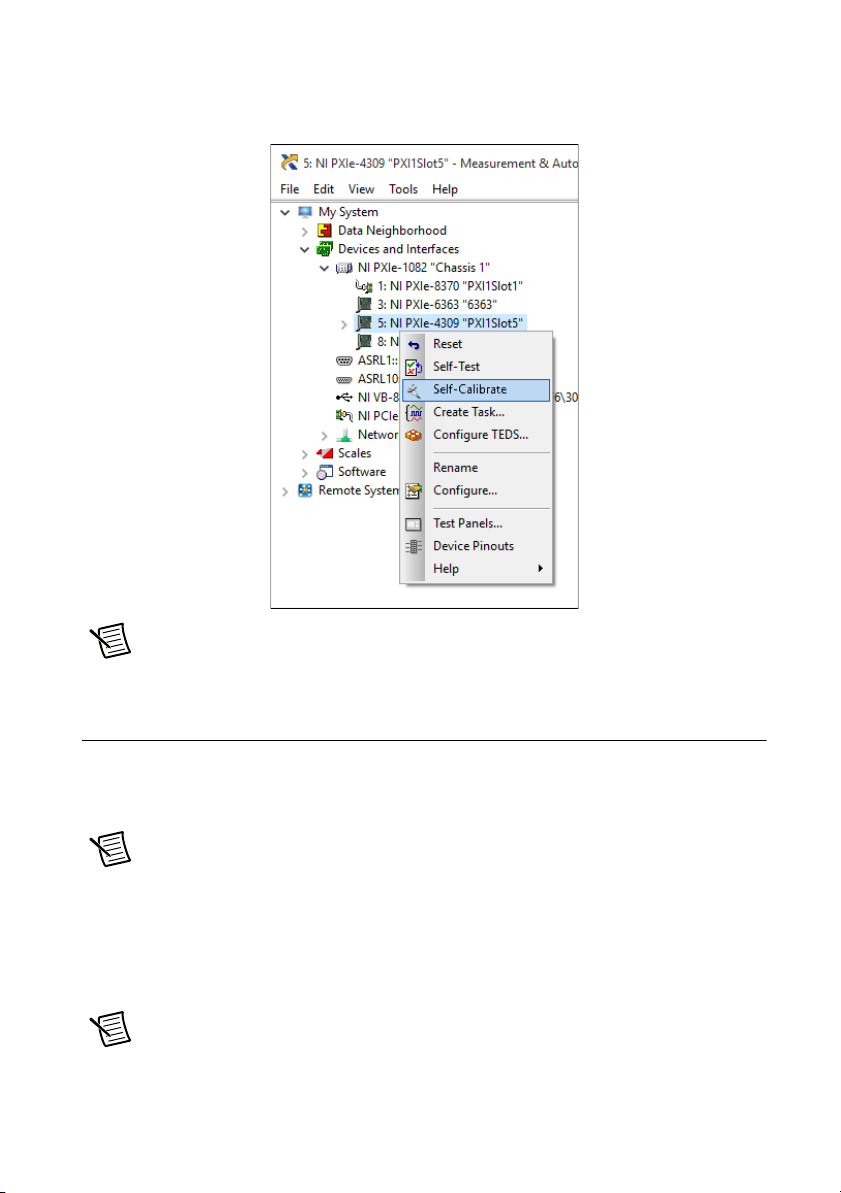
3. Select My System»Devices and Interfaces, and then select the PXIe-4309 device to self
calibrate.
4. Right-click the device and select Self-Calibrate.
Note Once self-calibration is completed, maintain ambient temperature within
±1 °C of the self-calibration temperature.
Verification
The following procedures describe the sequence of operation and provide test points required to
verify the PXIe-4309. The verification procedures assume that adequate traceable uncertainties
are available for the calibration references.
Note The verification procedure requires performing a self-calibration as a first
step unless self-verification is done immediately after an adjustment. Refer to the Self
Calibration section for instructions on performing a self calibration.
Warranted specifications have As-Found Limits (V) for verification before adjustment and
As-Left Limits (V) for reverification after adjustment. Warranted specifications unaffected by
adjustment have test limits with no additional qualification.
Note If any test fails verification or reverification, confirm that you have met the
Test Conditions before returning your device to NI. Refer to Worldwide Support and
Services for assistance in returning the device to NI.
PXIe-4309 Calibration Procedure | © National Instruments | 5
Page 6

DC Offset Accuracy
HI
LO
INTERNAL
REFERENCE
HI
LO
INPUT
CAL-4309 PXIe-4309
Complete the following steps to verify the DC offset accuracy:
1. Short input channels 0 through 31. Depending on the terminal block used for verification,
refer to step a or b for specifics about how to short the input channels of the PXIe-4309.
a. CAL-4309. Connect the double banana plug shorting bar to the input of the CAL-4309
as shown in Figure 1. This connection shorts all 32 input channels of the PXIe-4309.
i. Attach the CAL-4309 terminal block to the PXIe-4309 module.
ii. Tighten the mounting screw at the top of the terminal block to secure the terminal
block to the module.
iii. Wait ten minutes for the thermal EMF to stabilize.
iv. Connect the double banana plug shorting bar to the input of the CAL-4309 as
shown in Figure 1.
v. Wait two minutes for the thermal EMF to stabilize.
Figure 1. PXIe-4309 DC Offset Verification Setup Using the CAL-4309
b. TB-4309 (ST). Use nickel plated copper wire to short channels 0 through 31 as shown
in Figure 2.
i. Loosen the top cover screws and remove the top cover.
ii. Use nickel plated copper wire to short channels 0 through 31 as shown in
Figure 2.
iii. Reinstall the top cover and tighten the top cover screws.
iv. Attach the TB-4309 (ST) terminal block to the PXIe-4309 module.
v. Tighten the mounting screw at the top of the terminal block to secure the terminal
block to the module.
vi. Wait ten minutes for the thermal EMF to stabilize.
6 | ni.com | PXIe-4309 Calibration Procedure
Page 7

Figure 2. PXIe-4309 DC Offset Verification Setup Using the TB-4309 (ST)
A1
B1
C1
J12
1
R
COPYRIGHT 2016
C
TB–4309
J5 J6 J7 J8
J1 J2 J3 J4
FOR PATENTS: NI.COM/PATENTS
AI28–
AI29–
AI28+
AI29+
AI12–
AI13–
AI12+
AI13+
AI20–
AI21–
AI20+
AI21+
AI4–
AI5–
AI4+
AI5+
AI24–
AI25–
AI24+
AI25+
AI8–
AI9–
AI8+
AI9+
AI16–
AI17–
AI16+
AI17+
AI0–
AI1–
AI0+
AI1+
REF–REF+
J10 J11
AI30–
AI30+
AI14–
AI14+
AI22–
AI22+
AI6–
AI6+
AI26–
AI26+
AI10–
AI10+
AI18–
AI18+
AI2–
AI2+
R1
C2
U2
AI31–
AI31+
AI15–
AI15+
AI23–
AI23+
AI7–
AI7+
AI27–
AI27+
AI11–
AI11+
AI19–
AI19+
AI3–
AI3+
22
1 TB-4309 (ST) Terminal Block 2Aln Input Short
2. Verify the accuracy for each specified configuration in Table 2.
a. Configure an AI voltage channel task using the values in Table 3.
b. Start the task.
c. Acquire the samples with the PXIe-4309.
d. Drop the first sample acquired for each channel.
e. Average the remaining samples on a per channel basis.
f. Stop and clear the task.
g. Compare the averaged values to the specified test limits in Table 2.
C6
CR2
U4
CR1
R7
U3
C5
C1
U1
C3
UL94V–0
J9
PFI0
FRONT
PFI_GND
PFI1
PXIe-4309 Calibration Procedure | © National Instruments | 7
Page 8

Channels
Table 2. DC Offset Verification Test Limits
PXIe-4309 Configuration Test Limits (μV)
Input
Range
Auto Zero Chopping Lower Upper
AI0..31
±0.1 V
±1.0 V -10 10
*
None
**
Disabled
-6 6
±10 V -100 100
±15 V -150 150
±0.1 V
-5 5
AI0..31
±1.0 V
*
Once Disabled
±10 V -50 50
±15 V -75 75
±0.1 V
AI0..31
Every Sample Disabled -4 4
±1.0 V
*
±10 V
±15 V
±0.1 V
AI0..15
None Enabled -2 2
±1.0 V
†
±10 V
±15 V
*
Verification of channels 0 through 31 provides coverages of each of the 32 independent input paths of
the PXIe-4309.
**
Auto Zero None Test Limits include residual offset + temperature coefficient for ±1.0 °C.
†
Verification of channels 0 through 15 provides coverage of each of the 16 independent matching
chopping pairs of the PXIe-4309.
8 | ni.com | PXIe-4309 Calibration Procedure
Page 9

Table 3. AI Setup for DC Voltage Verification
Configuration Value
Physical Channels dev1/aix, where x refers to the channel number.
Input Range Input range from Table 2.
Input Terminal Configuration Differential
Rate 10 S/s
Sample Mode Finite
Samples per Channel 11
Auto Zero Auto Zero configuration from Table 2.
Chopping Chopping configuration from Table 2.
DC Voltage Accuracy
Complete the following steps to verify the DC voltage accuracy:
1. Connect the calibrator output to the input channel being tested. Depending on the terminal
block used for verification, refer to step a or b for specifics about how to connect the
calibrator output to the PXIe-4309 input.
Note Keep the test lead set loop area as small as possible.
a. CAL-4309. Use a low thermal EMF banana-to-banana test lead set to connect the
input of the CAL-4309 to the calibrator output as shown in Figure 3. This connects all
32 input channels of the PXIe-4309 to the calibrator output.
i. Attach the CAL-4309 terminal block to the PXIe-4309 module.
ii. Tighten the mounting screw at the top of the terminal block to secure the terminal
block to the module.
iii. Wait ten minutes for the thermal EMF to stabilize.
iv. Use a low thermal EMF banana-to-banana test lead set to connect the input of the
CAL-4309 to the calibrator output as shown in Figure 3.
v. Wait two minutes for the thermal EMF to stabilize.
PXIe-4309 Calibration Procedure | © National Instruments | 9
Page 10

CAL-4309
Calibration TB
OUTPUTASENSE
AUX
CURRENT
V-GUARD
GROUND
INTERNAL
REFERENCE
INPUT
For Calibration of
PXIe-4309 Only
30 VDC
CAL-4309
INPUT
Calibrator
HI
LO
HI
LO
Figure 3. PXIe-4309 DC Voltage Verification Setup Using CAL-4309.
b. TB-4309 (ST). Attach eight individual twisted-pair nickel-plated copper wires to
terminals AI0 through AI7 to allow the connection of the PXIe-4309 inputs to the
calibrator, one channel at a time.
i. Loosen the top cover screws and remove the top cover.
ii. Attach eight individual twisted-pair nickel-plated copper wires to AI0 through
AI7 to allow the connection of the PXIe-4309 inputs to the calibrator, one
channel at a time.
iii. Reinstall the top cover and tighten the top cover screws.
iv. Attach the TB-4309 (ST) terminal block to the PXIe-4309 module.
v. Tighten the mounting screw at the top of the terminal block to secure the terminal
block to the module.
vi. Wait ten minutes for the thermal EMF to stabilize.
10 | ni.com | PXIe-4309 Calibration Procedure
Page 11

Figure 4. PXIe-4309 DC Voltage Verification Setup Using TB-4309 (ST).
A1
B1
C1
J12
1
R
COPYRIGHT 2016
C
TB–4309
J5 J6 J7 J8
J1 J2 J3 J4
2
FOR PATENTS: NI.COM/PATENTS
AI28–
AI29–
AI28+
AI29+
AI12–
AI13–
AI12+
AI13+
AI20–
AI21–
AI20+
AI21+
AI4–
AI5–
AI4+
AI5+
AI24–
AI25–
AI24+
AI25+
AI8–
AI9–
AI8+
AI9+
AI16–
AI17–
AI16+
AI17+
AI0–
AI1–
AI0+
AI1+
J10 J11
3
REF–REF+
AI30–
AI30+
AI14–
AI14+
AI22–
AI22+
AI6–
AI6+
AI26–
AI26+
AI10–
AI10+
AI18–
AI18+
AI2–
AI2+
C6
CR2
U4
CR1
R1
R7
C2
U2
AI31–
AI31+
AI15–
AI15+
AI23–
AI23+
AI7–
AI7+
AI27–
AI27+
AI11–
AI11+
AI19–
AI19+
AI3+
U3
AI3–
C5
C1
U1
C3
PFI0
FRONT
PFI_GND
PFI1
1 TB-4309 (ST) Terminal Block 2 To Calibrator HI Input 3 To Calibrator LO Input
Note When using the TB-4309 (ST) or TB-4309 (MT) to perform the DC voltage
verification, connect only one channel to the calibrator at a time.
UL94V–0
J9
2. Verify that the calibrator output is not grounded (floating).
Note To float the output of the Fluke 5700A, enable External Guard mode
(EX GRD).
3. Set the calibrator voltage to 0 V.
4. Set the calibrator to Operate mode (OPR).
5. Verify the accuracy for each specified configuration in Table 4.
a. Set the calibrator to the listed configuration and allow it to settle.
b. Configure an AI voltage channel task using the values in Table 5.
c. Start the task.
d. Drop the first sample acquired for each channel.
e. Average the remaining samples on a per channel basis.
f. Stop and clear the task.
g. Compare the averaged values to the specified test limits in Table 4.
PXIe-4309 Calibration Procedure | © National Instruments | 11
Page 12

Table 4. DC Voltage Verification Test Limits
PXIe-4309
Configuration
Channels
†
AI0..7
Input
*
Range
±0.1 V +0.1 V 0.0999893 0.1000107 0.0999920 0.1000080
Calibrator
Settings
DCV
Amplitude
As-Found Limits (V) As-Left Limits (V)
Lower Upper Lower Upper
-0.1 V -0.1000107 -0.0999893 -0.1000080 -0.0999920
±1.0 V +1.0 V 0.9999357 1.0000643 0.9999627 1.0000373
-1.0 V -1.0000643 -0.9999357 -1.0000373 -0.9999627
±10 V +10 V 9.999445 10.000555 9.999715 10.000285
-10 V -10.000555 -9.999445 -10.000285 -9.999715
±15 V +15 V 14.999019 15.000981 14.999424 15.000576
-15 V -15.000981 -14.999019 -15.000576 -14.999424
*When using the TB-4309 (ST) or TB-4309 (MT) to perform the DC voltage verification, connect only
one channel to the calibrator at a time.
†Verification of channels 0 through 7 provides coverage of each of the 8 independent signal
conditioning paths and ADCs of the PXIe-4309.
12 | ni.com | PXIe-4309 Calibration Procedure
Page 13

Table 5. AI Setup for DC Voltage Verification
Configuration Value
Physical Channels dev1/aix, where x refers to the channel number.
Input Range Input range from Table 4
Input Terminal Configuration Differential
Rate 10 S/s
Sample Mode Finite
Samples per Channel 11
Auto Zero Every Sample
Chopping Disabled
Adjustment
An adjustment is required at least once every two years to warrant the published specifications
for the next calibration interval. An adjustment is recommended even if the PXIe-4309
successfully passed each verification procedures within the As-Left Limits (V) without
adjustment. Performing an adjustment procedure improves the device accuracy and resets the
calibration interval.
Upon successful completion of an adjustment procedure, the calibration constants, date, and
temperature in the device EEPROM are automatically updated.
To update the calibration date without performing an adjustment, refer to the instructions in the
EEPROM Update section.
The following procedure describes the sequence of operations required to adjust the PXIe-4309.
Depending on the terminal block used for verification, refer to step a or b for specifics about how
to connect the calibrator output to the PXIe-4309 input.
1. Measure the PXIe-4309 Internal Reference.
Note Keep the test lead set loop area as small as possible.
a. CAL-4309 — Use a low thermal EMF banana-to-banana test lead set to connect the
internal reference of the PXIe-4309 to the DMM input as shown in Figure 5.
i. Attach the CAL-4309 terminal block to the PXIe-4309 module.
ii. Tighten the mounting screw at the top of the terminal block to secure the terminal
block to the module.
iii. Wait ten minutes for the thermal EMF to stabilize.
PXIe-4309 Calibration Procedure | © National Instruments | 13
Page 14

iv. Use a low thermal EMF banana-to-banana test lead set to connect the internal
reference of the PXIe-4309 to the DMM input as shown in Figure 5.
v. Wait two minutes for the thermal EMF to stabilize.
Figure 5. PXIe-4309 Internal Reference Measurement Setup Using CAL-4309.
CAL-4309
INTERNAL
DMM
PXIe-4081
7 1/2-Digit DMM
REFERENCE
INPUT
INTERNAL
REFERENCE
For Calibration of
PXIe-4309 Only
30 VDC
HI
LO
HI
LO
b. TB-4309 (ST) — Use a low thermal EMF banana-to-probe test lead set to connect the
internal reference of the PXIe-4309 to the DMM input as shown in Figure 6.
i. Loosen the top cover screws and remove the top cover.
ii. Attach the TB-4309 (ST) terminal block to the PXIe-4309 module.
iii. Tighten the mounting screw at the top of the terminal block to secure the terminal
block to the module.
iv. Wait ten minutes for the thermal EMF to stabilize.
v. Use a low thermal EMF banana-to-probe test lead set to connect the internal
reference of the PXIe-4309 to the DMM input as shown in Figure 6.
vi. Wait two minutes for thermal EMF to stabilize.
14 | ni.com | PXIe-4309 Calibration Procedure
Page 15

Figure 6. PXIe-4309 Internal Reference Measurement Setup Using TB-4309 (ST)
A1
B1
C1
J12
1
R
COPYRIGHT 2016
C
TB–4309
J5 J6 J7 J8
J1 J2 J3 J4
FOR PATENTS: NI.COM/PATENTS
AI28–
AI29–
AI28+
AI29+
AI12–
AI13–
AI12+
AI13+
AI20–
AI21–
AI20+
AI21+
AI4–
AI5–
AI4+
AI5+
AI24–
AI25–
AI24+
AI25+
AI8–
AI9–
AI8+
AI9+
AI16–
AI17–
AI16+
AI17+
AI0–
AI1–
AI0+
AI1+
REF–REF+
J10 J11
AI30–
AI30+
AI14–
AI14+
AI22–
AI22+
AI6–
AI6+
AI26–
AI26+
AI10–
AI10+
AI18–
AI18+
AI2–
AI2+
C6
CR2
U4
CR1
R1
R7
C2
U2
AI31–
AI31+
AI15–
AI15+
AI23–
AI23+
AI7–
AI7+
AI27–
AI27+
AI11–
AI11+
AI19–
AI19+
AI3+
U3
AI3–
C5
C1
U1
C3
PFI_GND
32
1 TB-4309 (ST) 2 To DMM HI Input 3 To DMM LO Input
c. Configure the DMM using the values in Table 6.
Table 6. DMM Configuration
UL94V–0
J9
PFI0
FRONT
PFI1
Configuration Value
Measurement Vo l t a g e
Range 10 V
Digits of Resolution 7.5 digits
Aperture Time 100 ms
Input Impedance > 10 GΩ
Auto Zero On
ADC Calibration On
DC Noise rejection High Order
PXIe-4309 Calibration Procedure | © National Instruments | 15
Page 16

d. Use the DMM to measure the internal reference of the PXIe-4309 and record the
measurement for future use.
e. Compare the internal reference measurement to the test limits in Table 7.
Table 7. Internal Reference Test Limits
Lower Test Limit (V) Higher Test Limit (V)
6.741 7.298
Note If the reference measurement falls outside of the test limits, verify that the
measurement connections and configurations are correct.
2. Call
Use the calhandle out from this function to reference the current session.
3. Call the 4309 instance of DAQmx Adjust SC Express Calibration Polymorphic
4. Call DAQmx Close External Calibration (DAQmxCloseExtCal) to close the
5. Use the action
6. Use the action commit if you want to save the new calibration constants in the device
DAQmx Initialize External Calibration (DAQmxInitExtCal) with the
following parameters:
deviceName: Dev_name
password: NI (default)
(DAQmxAdjust4309Cal) and enter the measured internal reference value.
session.
cancel if there has been any error during the calibration or if you do not
want to save the new calibration constants in the device EEPROM.
EEPROM.
EEPROM Update
Upon successful completion of an adjustment procedure, the calibration constants, date, and
temperature in the device EEPROM are automatically updated.
You can update the calibration date and onboard calibration temperature without making any
adjustments by initializing an external calibration and closing the external calibration with a
commit action.
16 | ni.com | PXIe-4309 Calibration Procedure
Page 17

Reverification
After completing the adjustment procedure, repeat the Verification section for warranted
specifications that are affected by adjustment. Warranted specifications affected by the
adjustment procedure have As-Found Limits (V) for verification before adjustment and As-Left
Limits (V) for verification after adjustment.
Note If any test fails reverification, confirm that you have met the Test Conditions
before returning your device to NI. Refer to Worldwide Support and Services for
assistance in returning the device to NI.
Specifications
Refer to the PXIe-4309 Specifications document for detailed PXIe-4309 specification information.
Worldwide Support and Services
The NI website is your complete resource for technical support. At ni.com/support you have
access to everything from troubleshooting and application development self-help resources to
email and phone assistance from NI Application Engineers.
ni.com/services for NI Factory Installation Services, repairs, extended warranty, and
Visit
other services.
Visit ni.com/register to register your NI product. Product registration facilitates technical
support and ensures that you receive important information updates from NI.
A Declaration of Conformity (DoC) is our claim of compliance with the Council of the European
Communities using the manufacturer’s declaration of conformity. This system affords the user
protection for electromagnetic compatibility (EMC) and product safety. You can obtain the DoC
for your product by visiting
you can obtain the calibration certificate for your product at ni.com/calibration.
NI corporate headquarters is located at 11500 North Mopac Expressway, Austin, Texas,
78759-3504. NI also has offices located around the world. For telephone support in the United
States, create your service request at
For telephone support outside the United States, visit the Worldwide Offices section of
ni.com/niglobal to access the branch office websites, which provide up-to-date contact
information, support phone numbers, email addresses, and current events.
ni.com/certification. If your product supports calibration,
ni.com/support or dial 1 866 ASK MYNI (275 6964).
PXIe-4309 Calibration Procedure | © National Instruments | 17
Page 18

Information is subject to change without notice. Refer to the NI Trademarks and Logo Guidelines at ni.com/trademarks for more
information on NI trademarks. Other product and company names mentioned herein are trademarks or trade names of their respective
companies. For patents covering NI products/technology, refer to the appropriate location: Help»Patents in your software, the patents.txt
file on your media, or the National Instruments Patents Notice at ni.com/patents. You can find information about end-user license
agreements (EULAs) and third-party legal notices in the readme file for your NI product. Refer to the Export Compliance Information at
ni.com/legal/export-compliance for the NI global trade compliance policy and how to obtain relevant HTS codes, ECCNs, and
other import/export data. NI MAKES NO EXPRESS OR IMPLIED WARRANTIES AS TO THE ACCURACY OF THE INFORMATION
CONTAINED HEREIN AND SHALL NOT BE LIABLE FOR ANY ERRORS. U.S. Government Customers: The data contained in this manual
was developed at private expense and is subject to the applicable limited rights and restricted data rights as set forth in FAR 52.227-14, DFAR
252.227-7014, and DFAR 252.227-7015.
© 2017–2019 National Instruments. All rights reserved.
377026B-01 Aug19
 Loading...