

National Instruments PXIe-3610, PXIe-3620, PXIe-7902, mmRH-3602, mmRH-3603 Getting Started Manual
...Page 1

GETTING STARTED GUIDE
mmWave Transceiver System
2 GHz Bandwidth mmWave Transceiver System
This document explains how to install and configure the National Instruments millimeter wave
(mmWave) Transceiver System. The mmWave Transceiver System is a modular set of
hardware that can be used in various communications applications. This system ships with the
NI-mmWave instrument driver, which you can use to program the system.
Caution Observe all instructions and cautions in the user documentation. Using
the model in a manner not specified can damage the model and compromise the
built-in safety protection. Return damaged models to NI for repair.
Attention Suivez toutes les instructions et respectez toutes les mises en garde de la
documentation utilisateur. L'utilisation d'un modèle de toute autre façon que celle
spécifiée risque de l'endommager et de compromettre la protection de sécurité
intégrée. Renvoyez les modèles endommagés à NI pour réparation.
Caution If the device has been in use, it may exceed safe handling temperatures
and cause burns. Allow the device to cool before removing it from the chassis.
Attention Si l'appareil a été utilisé, il peut avoir atteint des températures trop
élevées pour être manipulé en toute sécurité, ce qui peut provoquer des brûlures.
Laisser l'appareil refroidir avant de le retirer du châssis.
Caution The system installation must adequately protect users' eyes from exposure
to millimeter wave radiation output and input signals from the transmitter and
receiver.
Attention L'installation du système doit protéger correctement les yeux des
utilisateurs contre l'exposition aux rayonnements d'ondes millimétriques des signaux
en entrée et en sortie provenant de l'émetteur et du récepteur.
Contents
Verifying the System Requirements..........................................................................................2
Unpacking the Kit..................................................................................................................... 2
System Configurations with mmWave Radio Heads........................................................ 4
Installing the Software.............................................................................................................. 7
Assembling mmWave Radio Head Tripods (mmRH-3647/3657)............................................ 7
Page 2

System Setup...........................................................................................................................10
Unidirectional System Setup...........................................................................................10
Bidirectional System Setup.............................................................................................27
Connecting mmWave Radio Heads to the System..........................................................38
Configuring the Coding Modules of a MIMO System................................................... 50
Programming the mmWave Transceiver System....................................................................57
NI-mmWave Instrument Driver...................................................................................... 57
Trigger Configuration............................................................................................................. 57
Signal Block Diagrams........................................................................................................... 59
24.25 GHz to 33.40 GHz mmWave Transceiver System Block Diagram...................... 59
37 GHz to 43.5 GHz mmWave Transceiver System Block Diagram............................. 59
71 GHz to 76 GHz mmWave Transceiver System Block Diagram................................ 60
Front Panels, Back Panels, and Connectors............................................................................60
Direct Connections to the mmWave Transceiver System...............................................60
PXIe-3610 Front Panel and LEDs.................................................................................. 61
PXIe-3620 Front Panel....................................................................................................63
PXIe-3630 Front Panel and LEDs.................................................................................. 65
PXIe-7902 Front Panel....................................................................................................67
mmRH-3602 Front/Back Panel and LEDs......................................................................68
mmRH-3603 Front/Back Panel and LEDs......................................................................71
mmRH-3642 Front/Back Panel and LEDs......................................................................74
mmRH-3643 Front/Back Panel and LEDs......................................................................76
mmRH-3647 Front/Back Panel and LEDs......................................................................78
mmRH-3652 Front/Back Panel and LEDs......................................................................80
mmRH-3653 Front/Back Panel and LEDs......................................................................82
mmRH-3657 Front/Back Panel and LEDs......................................................................84
Where to Go Next................................................................................................................... 85
Verifying the System Requirements
To use the NI-mmWave instrument driver, your system must meet certain requirements.
Refer to the product readme, which is available online at ni.com/manuals, for more
information about minimum system requirements, recommended system, and supported
application development environments (ADEs).
Unpacking the Kit
Each mmWave Transceiver System configuration includes chassis, modules, and cables.
Additional chassis, devices, and cables may be included depending on added options.
2 | ni.com | mmWave Transceiver System Getting Started Guide
Page 3

Table 1. Kit Contents by Configuration
Configuration Required MIMO Coding Option
Unidirectional single
input, single output
(SISO) (baseband)
• Receiver (RX) chassis
• Transmitter (TX) chassis
• Mini-SAS HD(m)-to-Mini-SAS
HD(m) (8.25 in.) cables (x9)
—
Unidirectional SISO
(baseband and
intermediate frequency
(IF))
• RX chassis
• TX chassis
• Mini-SAS HD(m)-to-Mini-SAS
HD(m) (8.25 in.) cables (x9)
• MMPX(m)-to-MMPX(m) cables
(x8)
—
Unidirectional
multiple-input,
multiple-output
(MIMO) (baseband)
• RX chassis
• TX chassis
• Mini-SAS HD(m)-to-Mini-SAS
HD(m) (8.25 in.) cables (x19)
• Coding chassis
• Mini-SAS HD(m)to-Mini-SAS
HD(m) (18 in.)
cables (x2)
Unidirectional MIMO
(baseband and IF)
• RX chassis
• TX chassis
• Mini-SAS HD(m)-to-Mini-SAS
HD(m) (8.25 in.) cables (x19)
• MMPX(m)-to-MMPX(m) cables
(x16)
• Coding chassis
• Mini-SAS HD(m)to-Mini-SAS
HD(m) (18 in.)
cables (x2)
Bidirectional SISO
(baseband)
• RX/TX chassis (x2)
• Mini-SAS HD(m)-to-Mini-SAS
HD(m) (8.25 in.) cables (x18)
—
Bidirectional SISO
(baseband and IF)
• RX/TX chassis (x2)
• Mini-SAS HD(m)-to-Mini-SAS
HD(m) (8.25 in.) cables (x18)
• MMPX(m)-to-MMPX(m) cables
(x16)
—
mmWave Transceiver System Getting Started Guide | © National Instruments | 3
Page 4

Table 1. Kit Contents by Configuration (Continued)
Configuration Required MIMO Coding Option
Bidirectional MIMO
(baseband)
• RX/TX chassis (x2)
• Mini-SAS HD(m)-to-Mini-SAS
HD(m) (8.25 in.) cables (x38)
• Coding chassis
(x2)
• Mini-SAS HD(m)to-Mini-SAS
HD(m) (18 in.)
cables (x4)
Bidirectional MIMO
(baseband and IF)
• RX/TX chassis (x2)
• Mini-SAS HD(m)-to-Mini-SAS
HD(m) (8.25 in.) cables (x38)
• MMPX(m)-to-MMPX(m) cable
(x32)
• Coding chassis
(x2)
• Mini-SAS HD(m)to-Mini-SAS
HD(m) (18 in.)
cables (x4)
System Configurations with mmWave Radio Heads
You can choose to connect your system to a selection of the following mmWave radio heads:
• mmRH-3602 mmWave Radio Head
• mmRH-3603 mmWave Radio Head
• mmRH-3642 mmWave Radio Head
• mmRH-3643 mmWave Radio Head
• mmRH-3647 mmWave Radio Head
• mmRH-3652 mmWave Radio Head
• mmRH-3653 mmWave Radio Head
• mmRH-3657 mmWave Radio Head
4 | ni.com | mmWave Transceiver System Getting Started Guide
Page 5

Table 2. Unidirectional System Configurations with mmWave Radio Heads
Configuration mmRH-3642/3643/3652/3653 mmRH-3602/3603 mmRH-3647/3657
Unidirectional
SISO
(baseband)
— — —
Unidirectional
SISO
(baseband and
IF)
• mmRH-3642/3643
• mmRH-3652/3653
• Single-channel EPLSP
cables (x2)
• Digital I/O (DIO) adapters
(x2)
• HDMI(m)-to-miniHDMI(m) cables (x2)
• SMA(m)-to-SMA(m)
cables (x4)
—
• mmRH-3647
• mmRH-3657
• mmWave radio
head tripods
(x2)
• Single-channel
EPLSP cables
(x2)
• SMA(m)-toSMA(m) cables
(x4)
Unidirectional
MIMO
(baseband)
— — —
Unidirectional
MIMO
(baseband and
IF)
• mmRH-3642/3643 (x2)
• mmRH-3652/3653 (x2)
• Single-channel EPLSP
cables (x4)
• DIO adapter modules (x4)
• HDMI(m)-to-miniHDMI(m) cables (x4)
• SMA(m)-to-SMA(m)
cables (x8)
—
• mmRH-3647
(x2)
• mmRH-3657
(x2)
• mmWave radio
head tripods
(x4)
• Single-channel
EPLSP cables
(x4)
• SMA(m)-toSMA(m) cables
(x8)
mmWave Transceiver System Getting Started Guide | © National Instruments | 5
Page 6

Table 3. Bidirectional System Configurations with mmWave Radio Heads
Configuration mmRH-3642/3643/3652/3653 mmRH-3602/3603 mmRH-3647/3657
Bidirectional
SISO
(baseband)
— — —
Bidirectional
SISO
(baseband and
IF)
• mmRH-3642/3643 (x2)
• mmRH-3652/3653 (x2)
• Dual-channel EPLSP
cables (x2)
• DIO adapter modules
(x4)
• HDMI(m)-to-miniHDMI(m) cables (x4)
• SMA(m)-to-SMA(m)
cables (x8)
• mmRH-3602/3603
(x2)
• Single-channel
EPLSP cables (x2)
• DIO adapter
modules (x2)
• HDMI(m)-tomini-HDMI(m)
cables (x2)
• SMA(m)-toSMA(m) cables
(x8)
• mmRH-3647
(x2)
• mmRH-3657
(x2)
• mmWave
radio head
tripods (x4)
• Dual-channel
EPLSP
cables (x4)
• SMA(m)-toSMA(m)
cables (x8)
Bidirectional
MIMO
(baseband)
— — —
Bidirectional
MIMO
(baseband and
IF)
• mmRH-3642/3643 (x4)
• mmRH-3652/3653 (x4)
• Dual-channel EPLSP
cables (x4)
• DIO adapter modules
(x8)
• HDMI(m)-to-miniHDMI(m) cables (x8)
• SMA(m)-to-SMA(m)
cables (x16)
• mmRH-3602/3603
(x4)
• Single-channel
EPLSP cables (x4)
• DIO adapter
modules (x4)
• HDMI(m)-tomini-HDMI(m)
cables (x4)
• SMA(m)-toSMA(m) cables
(x16)
• mmRH-3647
(x4)
• mmRH-3657
(x4)
• mmWave
radio head
tripods (x8)
• Dual-channel
EPLSP
cables (x8)
• SMA(m)-toSMA(m)
cables (x16)
6 | ni.com | mmWave Transceiver System Getting Started Guide
Page 7

You can simultaneously connect different models of mmWave radio heads to the mmWave
Transceiver System. However, connecting models with different IF frequency ranges, such as
the mmRH-3642 and the mmRH-3647, may cause a non-ideal IF frequency to be used.
Related Information
Refer to the mmWave Transceiver System Specifications on ni.com for IF frequency ranges by
model.
Installing the Software
You must be an Administrator to install NI software on your computer.
1. Install an ADE, such as LabVIEW.
2. Install NI LabVIEW FPGA Module.
3. (Recommended) Install the latest service pack for LabVIEW and any LabVIEW modules
you are using.
4. Visit ni.com/info and enter the Info Code mmwavedriver to access the driver download
page for the latest NI-mmWave software.
5. Download the NI-mmWave driver software.
6. Run setup.exe.
7. Follow the instructions in the installation prompts.
Note Windows users may see access and security messages during
installation. Accept the prompts to complete the installation.
8. When the installer completes, select Restart in the dialog box that prompts you to restart,
shut down, or restart later.
Related Information
Programming the mmWave Transceiver System on page 57
Assembling mmWave Radio Head Tripods
(mmRH-3647/3657)
Complete the following steps to assemble the mmWave radio head tripods if your
configuration includes mmWave radio heads and tripod stability is desired.
1. Install four 3/4 in. screws as shown in the following figure. Do not tighten.
mmWave Transceiver System Getting Started Guide | © National Instruments | 7
Page 8
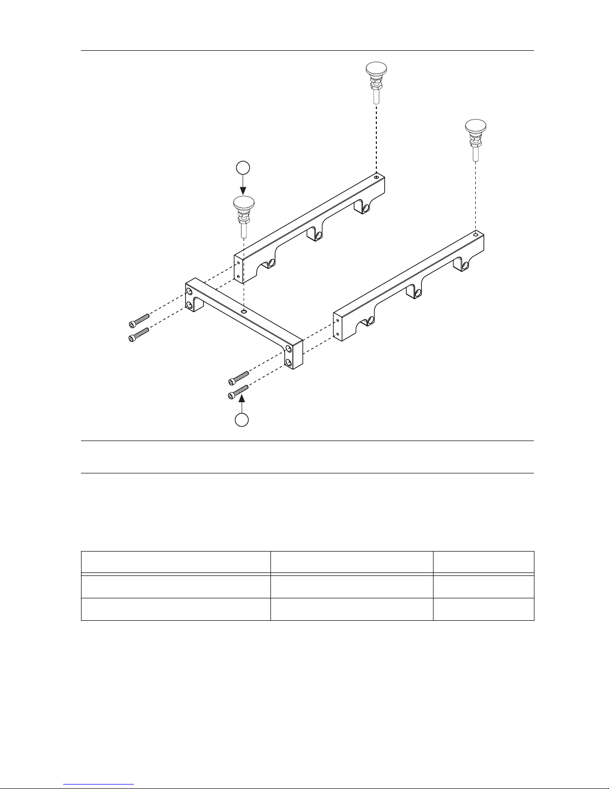
Figure 1. Assembling the Tripod
158972B–01
REV XX
158972B–01
REV XX
1
2
1. 3/4 in. Screws
2. Stud Leveling Feet
2. Install three stud leveling feet as shown in the previous figure and use to adjust the
mmWave radio head to the desired mounting height. Jam nuts may be tightened to lock
height adjustment according to the specifications in the following table.
Table 4. Tightening Requirements for mmWave Radio Head Tripods
Item Max Torque (in. x lb) Driver Size
3/4 in. and 1/2 in. screws 11.5 7/64 in. hex
Stud leveling foot jam nut 11.5 3/8 in. hex
3. Install the mmWave radio head using six 1/2 in. screws as shown in the following figure
and tighten them according to the specifications in Table 4.
8 | ni.com | mmWave Transceiver System Getting Started Guide
Page 9
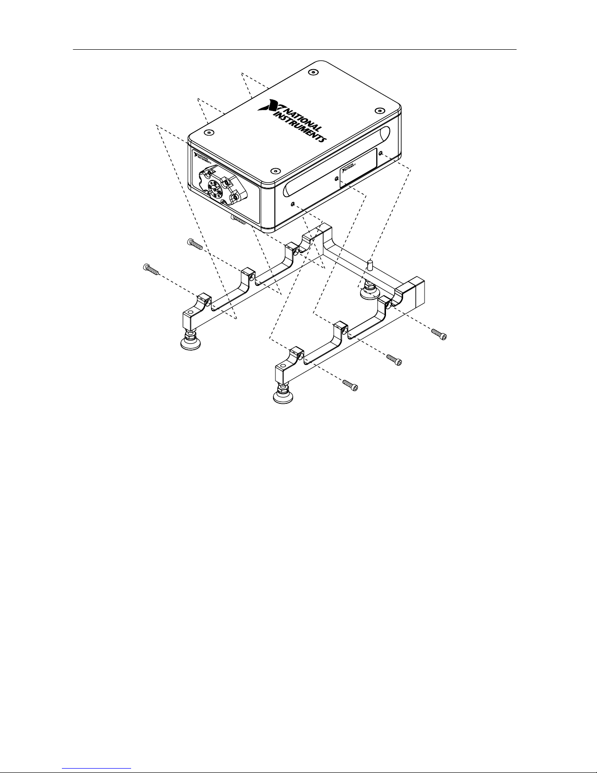
Figure 2. Assembling the Tripod with the mmWave Radio Head
4. Tighten the 3/4 in. screws according to the specifications in Table 4.
mmWave Transceiver System Getting Started Guide | © National Instruments | 9
Page 10
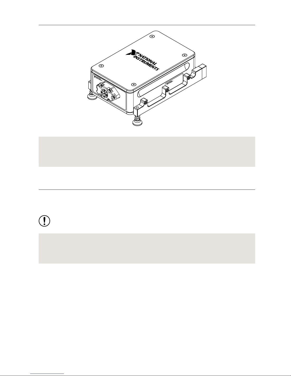
Figure 3. Completed Tripod and mmWave Radio Head Assembly
Related Information
Connecting mmRH-3647/3657 Radio Heads to a Bidirectional System on page 49
Connecting mmRH-3647/3657 Radio Heads to a Unidirectional System on page 42
System Setup
This section describes how to connect the modules of your mmWave Transceiver System.
The mmWave Transceiver System modules arrive pre-installed in the chassis.
Notice Modifying or reserving system-required PXI triggers will cause runtime
synchronization errors and prohibit system function.
Related Information
Trigger Configuration on page 57
Refer to the NI-mmWave Manual on ni.com for more information about trigger routing.
Unidirectional System Setup
This section describes how to connect the modules of a unidirectional mmWave Transceiver
System.
Unidirectional mmWave Transceiver System configurations are as follows:
• Unidirectional SISO (baseband)
• Unidirectional SISO (baseband and IF)
• Unidirectional MIMO (baseband)
• Unidirectional MIMO (baseband and IF)
10 | ni.com | mmWave Transceiver System Getting Started Guide
Page 11

Each configuration consists of two chassis, identical except for the unique components listed
in the following table.
Table 5. Unique Components of Unidirectional System Chassis
Chassis Unique Component
RX PXIe-3630 Digitizer
TX PXIe-3610 Waveform Generator
Interconnecting the Unidirectional SISO (Baseband) Modules
Complete the following steps to connect the modules of the unidirectional SISO (baseband)
mmWave Transceiver System configuration.
1. Connect the adjoining PXIe-3630 and PXIe-7902 High-Speed Serial Instrument modules
in the RX chassis using four Mini-SAS HD(m)-to-Mini-SAS HD(m) (8.25 in.) cables.
a) Connect the 0 connector of the PXIe-3630 front panel to the PORT 0 connector of
the PXIe-7902 front panel.
b) Connect the 1 connector of the PXIe-3630 front panel to the PORT 1 connector of
the PXIe-7902 front panel.
c) Connect the 2 connector of the PXIe-3630 front panel to the PORT 2 connector of
the PXIe-7902 front panel.
d) Connect the 3 connector of the PXIe-3630 front panel to the PORT 3 connector of
the PXIe-7902 front panel.
mmWave Transceiver System Getting Started Guide | © National Instruments | 11
Page 12

Figure 4. Interconnecting the PXIe-3630 and PXIe-7902 Modules
PXIe-3630
I/Q Digitizer
REF IN
+10 dBm
NOM
+13 dBm
MAX
1.5 Vp-p
DIFF MAX
1.5 Vp-p
DIFF MAX
0 V
cm
ALL PORTS 50 Ω
REF
OUT
0
1
2
3
Q+
Q–
I+
I–
ACCESS ACTIVE
PXIe-7902
CLK
IN
PORT
2
PORT
4
PORT
5
PORT
3
PORT
0
PORT
1
1
1. Mini-SAS HD(m)-to-Mini-SAS HD(m) (8.25 in.) Cables
2. Connect the PORT 4 connector of the PXIe-7902 front panel to the PORT 4 connector of
the PXIe-7902 front panel using a Mini-SAS HD(m)-to-Mini-SAS HD(m) (8.25 in.)
cable.
12 | ni.com | mmWave Transceiver System Getting Started Guide
Page 13
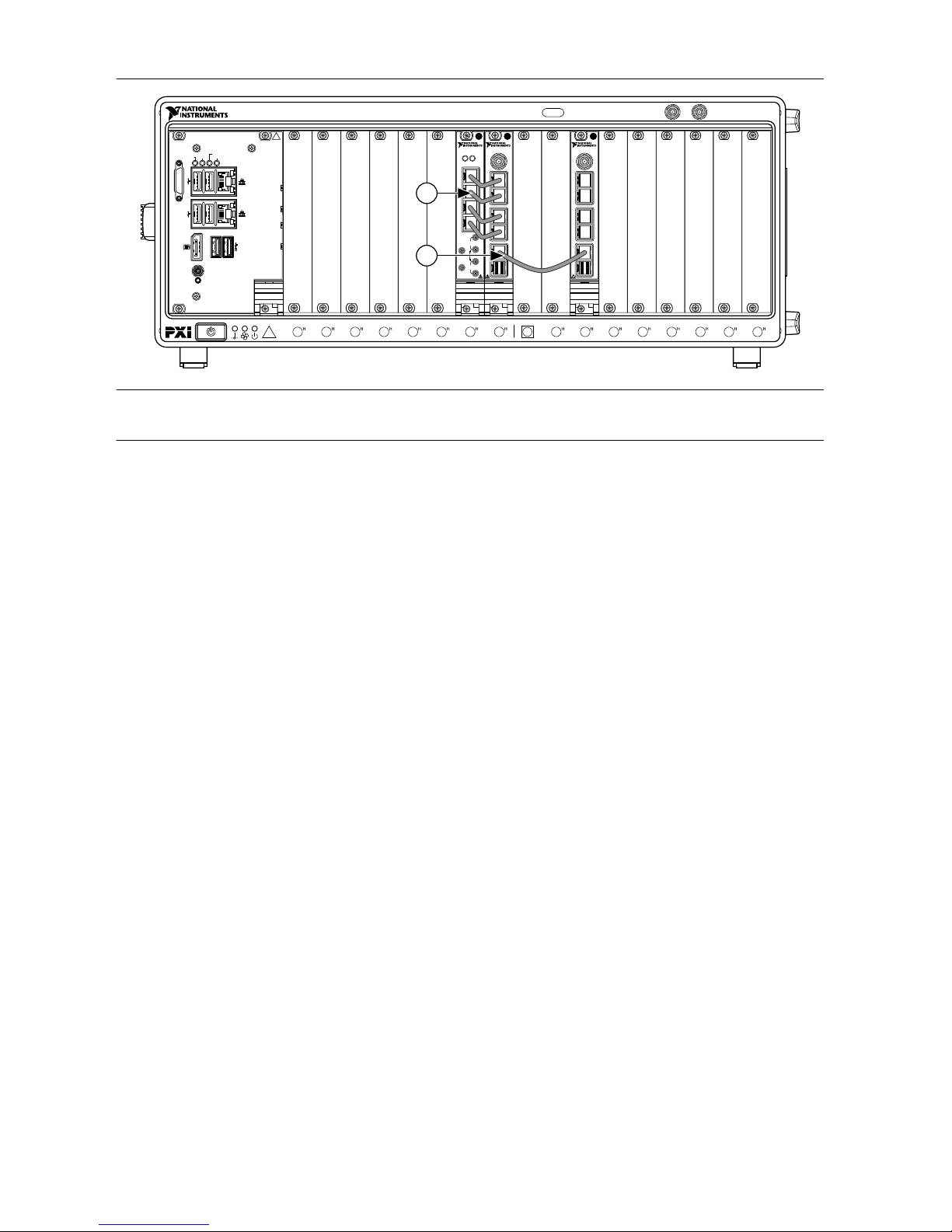
Figure 5. Unidirectional SISO (Baseband) RX Chassis
PXIe-7902
CLK
IN
PORT
2
PORT
3
PORT
4
PORT
5
PORT
0
PORT
1
PXIe-7902
CLK
IN
PORT
2
PORT
3
PORT
4
PORT
5
PORT
0
PORT
1
PXIe-3630
I/Q Digitizer
REF IN
+10 dBm
NOM
+13 dBm
MAX
1.5 Vp-p
DIFF MAX
1.5 Vp-p
DIFF MAX
0 V
cm
ALL PORTS 50 Ω
REF
OUT
0
1
2
3
Q+
Q–
I+
I–
ACCESS ACTIVE
213 4 5 6 7 8 9
11
12
13
14
15
16
17
18
10
NI PXIe-1085
10 MHz REF OUT IN
24 GB/s
Embedded Controller
RESET
TRIG
ACT/
LINK
ACT/
LINK
2
1
10/100
/1000
10/100
/1000
USER1
USER2
PWR OK/
FAULT
DRIVEGPIB
1
2
1. Mini-SAS HD(m)-to-Mini-SAS HD(m) (8.25 in.) Cables
2. Mini-SAS HD(m)-to-Mini-SAS HD(m) (8.25 in.) Cable
3. Connect the adjoining PXIe-7902 and PXIe-3610 modules in the TX chassis using four
Mini-SAS HD(m)-to-Mini-SAS HD(m) (8.25 in.) cables.
a) Connect the PORT 0 connector of the PXIe-7902 front panel to the 0 connector of
the PXIe-3610 front panel.
b) Connect the PORT 1 connector of the PXIe-7902 front panel to the 1 connector of
the PXIe-3610 front panel.
c) Connect the PORT 2 connector of the PXIe-7902 front panel to the 2 connector of
the PXIe-3610 front panel.
d) Connect the PORT 3 connector of the PXIe-7902 front panel to the 3 connector of
the PXIe-3610 front panel.
mmWave Transceiver System Getting Started Guide | © National Instruments | 13
Page 14
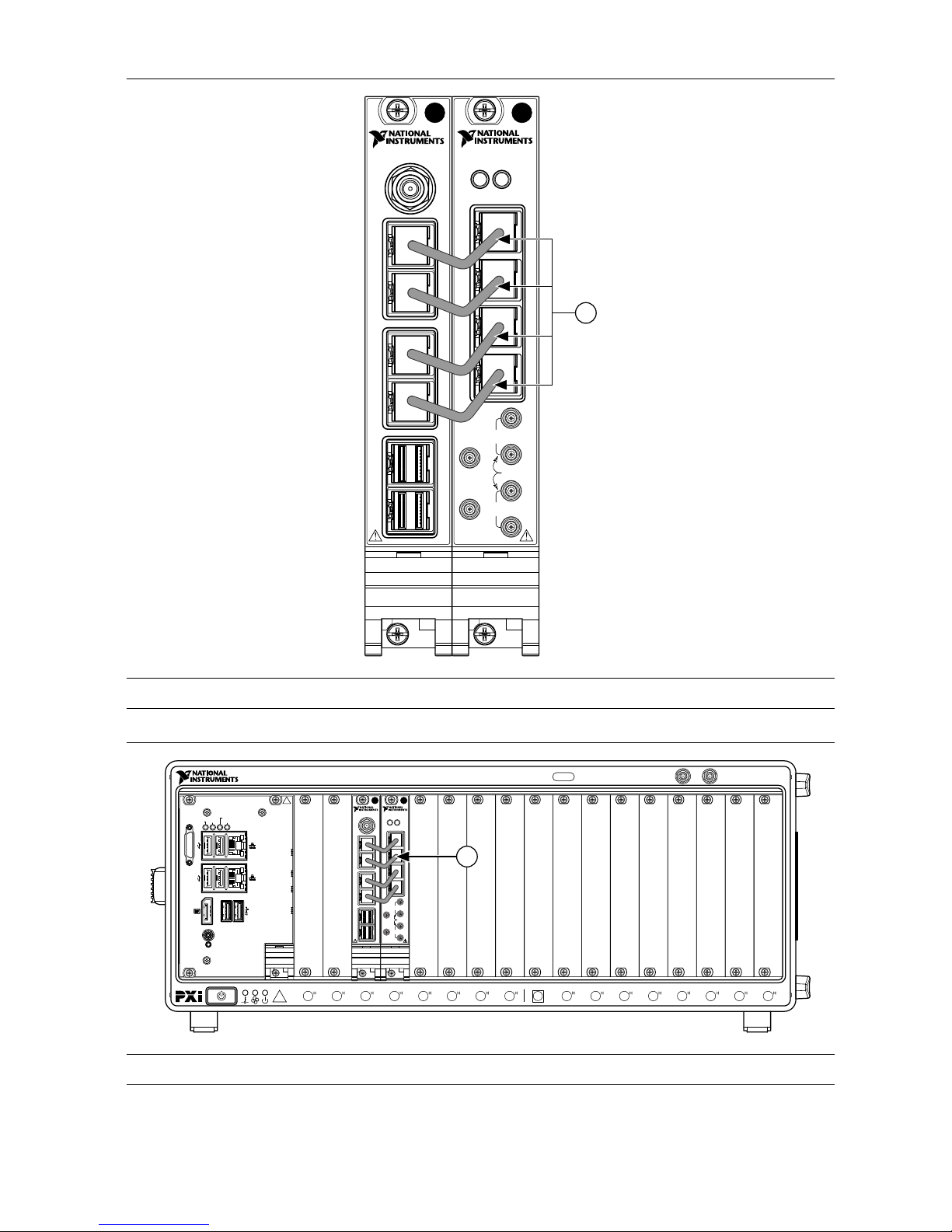
Figure 6. Interconnecting the PXIe-7902 and PXIe-3610 Modules
PXIe-3610
I/Q Generator
PXIe-7902
0
1
2
3
REF IN
+10 dBm
NOM
+13 dBm
MAX
2 Vp-p
DIFF MAX
2 Vp-p
DIFF MAX
0 V
cm
ALL PORTS 50 Ω
REF
OUT
Q+
Q–
I+
I–
PORT
4
PORT
5
PORT
2
PORT
3
PORT
0
PORT
1
ACCESS ACTIVE
CLK
IN
1
1. Mini-SAS HD(m)-to-Mini-SAS HD(m) (8.25 in.) Cables
Figure 7. Unidirectional SISO (Baseband) TX Chassis
213 4 5 6 7 8 9
11
12
13
14
15
16
17
18
10
NI PXIe-1085
10 MHz REF OUT IN
24 GB/s
Embedded Controller
RESET
TRIG
ACT/
LINK
ACT/
LINK
2
1
10/100
/1000
10/100
/1000
USER1
USER2
PWR OK/
FAULT
DRIVEGPIB
PXIe-3610
I/Q Generator
0
1
2
3
REF IN
+10 dBm
NOM
+13 dBm
MAX
2 Vp-p
DIFF MAX
2 Vp-p
DIFF MAX
0 V
cm
ALL PORTS 50 Ω
REF
OUT
Q+
Q–
I+
I–
ACCESS ACTIVE
PXIe-7902
PORT
4
PORT
5
PORT
2
PORT
3
PORT
0
PORT
1
CLK
IN
1
1. Mini-SAS HD(m)-to-Mini-SAS HD(m) (8.25 in.) Cables
14 | ni.com | mmWave Transceiver System Getting Started Guide
Page 15

Disconnect cables or otherwise attenuate the signal to ensure that no signal is entering the
baseband ports on the PXIe-3630 module during system startup.
Interconnecting the Unidirectional SISO (Baseband and IF)
Modules
Complete the following steps to connect the modules of the unidirectional SISO (baseband and
IF) mmWave Transceiver System configuration.
1. Connect the adjoining PXIe-3620 RF Upconverter and Downconverter Module and
PXIe-3630 modules in the RX chassis using four MMPX(m)-to-MMPX(m) cables.
a) Connect the RX I+ connector of the PXIe-3620 front panel to the I+ connector of the
PXIe-3630 front panel.
b) Connect the RX I– connector of the PXIe-3620 front panel to the I– connector of the
PXIe-3630 front panel.
c) Connect the RX Q+ connector of the PXIe-3620 front panel to the Q+ connector of
the PXIe-3630 front panel.
d) Connect the RX Q– connector of the PXIe-3620 front panel to the Q– connector of
the PXIe-3630 front panel.
2. Connect the adjoining PXIe-3630 and PXIe-7902 modules in the RX chassis using four
Mini-SAS HD(m)-to-Mini-SAS HD(m) (8.25 in.) cables.
a) Connect the 0 connector of the PXIe-3630 front panel to the PORT 0 connector of
the PXIe-7902 front panel.
b) Connect the 1 connector of the PXIe-3630 front panel to the PORT 1 connector of
the PXIe-7902 front panel.
c) Connect the 2 connector of the PXIe-3630 front panel to the PORT 2 connector of
the PXIe-7902 front panel.
d) Connect the 3 connector of the PXIe-3630 front panel to the PORT 3 connector of
the PXIe-7902 front panel.
mmWave Transceiver System Getting Started Guide | © National Instruments | 15
Page 16
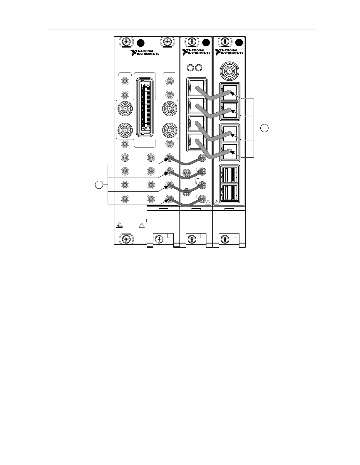
Figure 8. Interconnecting the PXIe-3620, PXIe-3630, and PXIe-7902 Modules
NI PXIe-3620
IF-LO Module, 2 GHz BW
TX
LO1
IN
LO1
IF OUT IF IN
IF SYNC INIF SYNC OUT
REF IN
REF OUT
LO2 OUT
ESD
SENSITIVE
LO2 IN
I+
I–
Q+
Q–
I+
I–
Q+
Q–
DIGITAL I/O
LVTTL
LO1
LO1
OUT
LO1
IN
LO1
OUT
RXmmWave
PXIe-3630
I/Q Digitizer
REF IN
+10 dBm
NOM
+13 dBm
MAX
1.5 Vp-p
DIFF MAX
1.5 Vp-p
DIFF MAX
0 V
cm
ALL PORTS 50 Ω
REF
OUT
0
1
2
3
Q+
Q–
I+
I–
ACCESS ACTIVE
PXIe-7902
CLK
IN
PORT
2
PORT
4
PORT
5
PORT
3
PORT
0
PORT
1
2
1
1. Mini-SAS HD(m)-to-Mini-SAS HD(m) (8.25 in.) Cables
2. MMPX(m)-to-MMPX(m) Cables
3. Connect the PORT 4 connector of the PXIe-7902 front panel to the PORT 4 connector of
the PXIe-7902 front panel using a Mini-SAS HD(m)-to-Mini-SAS HD(m) (8.25 in.)
cable.
16 | ni.com | mmWave Transceiver System Getting Started Guide
Page 17
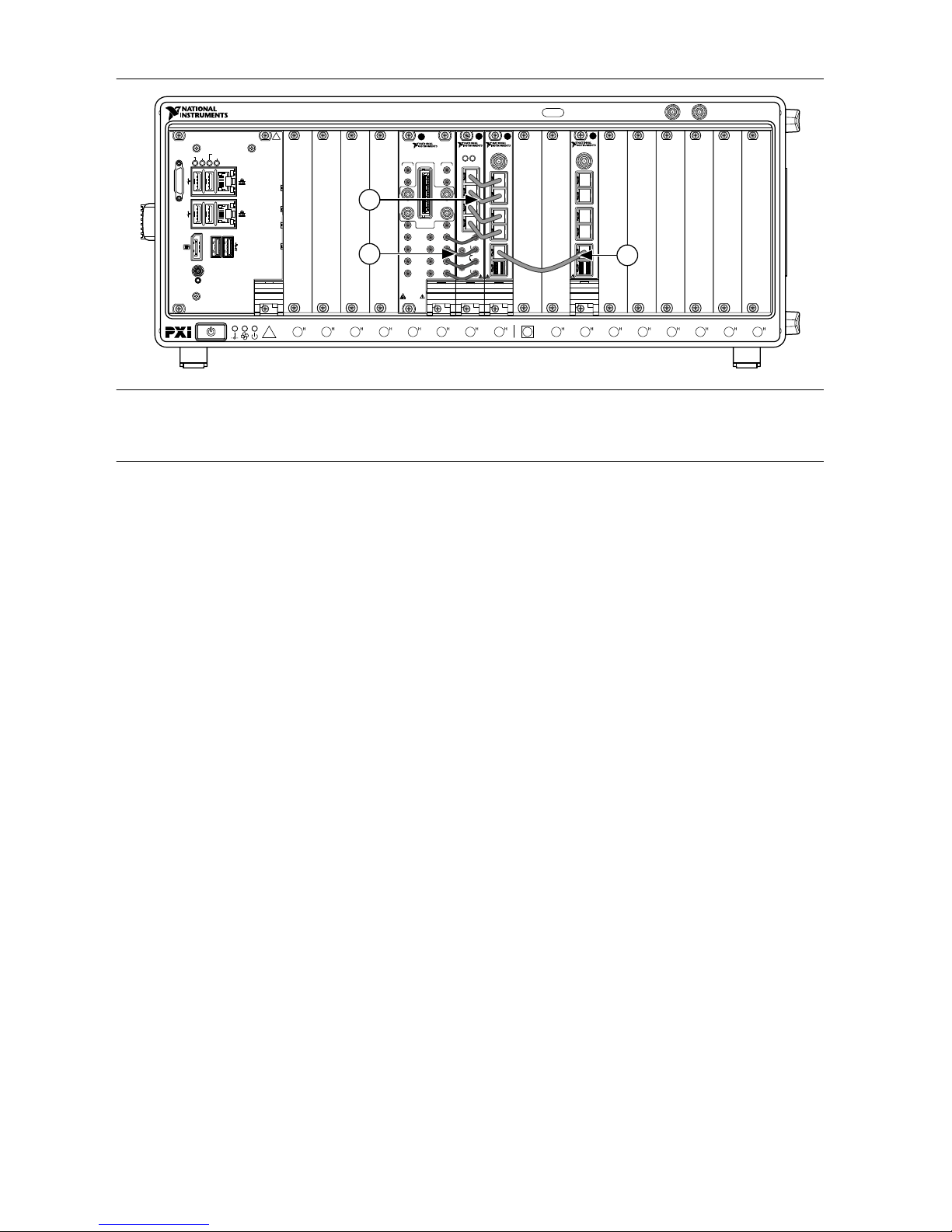
Figure 9. Unidirectional SISO (Baseband and IF) RX Chassis
PXIe-7902
CLK
IN
PORT
2
PORT
3
PORT
4
PORT
5
PORT
0
PORT
1
PXIe-3630
I/Q Digitizer
REF IN
+10 dBm
NOM
+13 dBm
MAX
1.5 Vp-p
DIFF MAX
1.5 Vp-p
DIFF MAX
0 V
cm
ALL PORTS 50 Ω
REF
OUT
0
1
2
3
Q+
Q–
I+
I–
ACCESS ACTIVE
213 4 5 6 7 8 9
11
12
13
14
15
16
17
18
10
NI PXIe-1085
10 MHz REF OUT IN
24 GB/s
Embedded Controller
RESET
TRIG
ACT/
LINK
ACT/
LINK
2
1
10/100
/1000
10/100
/1000
USER1
USER2
PWR OK/
FAULT
DRIVEGPIB
NI PXIe-3620
IF-LO Module, 2 GHz BW
TX
LO1
IN
LO1
IF OUT IF IN
IF SYNC INIF SYNC OUT
REF IN
REF OUT
LO2 OUT
ESD
SENSITIVE
LO2 IN
I+
I–
Q+
Q–
I+
I–
Q+
Q–
DIGITAL I/O
LVTTL
LO1
LO1
OUT
LO1
IN
LO1
OUT
RXmmWave
PXIe-7902
CLK
IN
PORT
2
PORT
3
PORT
4
PORT
5
PORT
0
PORT
1
3
2
1
1. Mini-SAS HD(m)-to-Mini-SAS HD(m) (8.25 in.) Cables
2. MMPX(m)-to-MMPX(m) Cables
3. Mini-SAS HD(m)-to-Mini-SAS HD(m) (8.25 in.) Cable
4. Connect the adjoining PXIe-3610 and PXIe-3620 modules in the TX chassis using four
MMPX(m)-to-MMPX(m) cables.
a) Connect the I+ connector of the PXIe-3610 front panel to the TX I+ connector of the
PXIe-3620 front panel.
b) Connect the I– connector of the PXIe-3610 front panel to the TX I– connector of the
PXIe-3620 front panel.
c) Connect the Q+ connector of the PXIe-3610 front panel to the TX Q+ connector of
the PXIe-3620 front panel.
d) Connect the Q– connector of the PXIe-3610 front panel to the TX Q– connector of
the PXIe-3620 front panel.
5. Connect the adjoining PXIe-7902 and PXIe-3610 modules in the TX chassis using four
Mini-SAS HD(m)-to-Mini-SAS HD(m) (8.25 in.) cables.
a) Connect the PORT 0 connector of the PXIe-7902 front panel to the 0 connector of
the PXIe-3610 front panel.
b) Connect the PORT 1 connector of the PXIe-7902 front panel to the 1 connector of
the PXIe-3610 front panel.
c) Connect the PORT 2 connector of the PXIe-7902 front panel to the 2 connector of
the PXIe-3610 front panel.
d) Connect the PORT 3 connector of the PXIe-7902 front panel to the 3 connector of
the PXIe-3610 front panel.
mmWave Transceiver System Getting Started Guide | © National Instruments | 17
Page 18

Figure 10. Interconnecting the PXIe-7902, PXIe-3610, and PXIe-3620 Modules
PXIe-3610
I/Q Generator
0
1
2
3
REF IN
+10 dBm
NOM
+13 dBm
MAX
2 Vp-p
DIFF MAX
2 Vp-p
DIFF MAX
0 V
cm
ALL PORTS 50 Ω
REF
OUT
Q+
Q–
I+
I–
ACCESS ACTIVE
PXIe-7902
PORT
4
PORT
5
PORT
2
PORT
3
PORT
0
PORT
1
CLK
IN
NI PXIe-3620
IF-LO Module, 2 GHz BW
TX
LO1
IN
LO1
IF OUT IF IN
IF SYNC INIF SYNC OUT
REF IN
REF OUT
LO2 OUT
ESD
SENSITIVE
LO2 IN
I+
I–
Q+
Q–
I+
I–
Q+
Q–
DIGITAL I/O
LVTTL
LO1
LO1
OUT
LO1
IN
LO1
OUT
RXmmWave
2
1
1. Mini-SAS HD(m)-to-Mini-SAS HD(m) (8.25 in.) Cables
2. MMPX(m)-to-MMPX(m) Cables
18 | ni.com | mmWave Transceiver System Getting Started Guide
Page 19
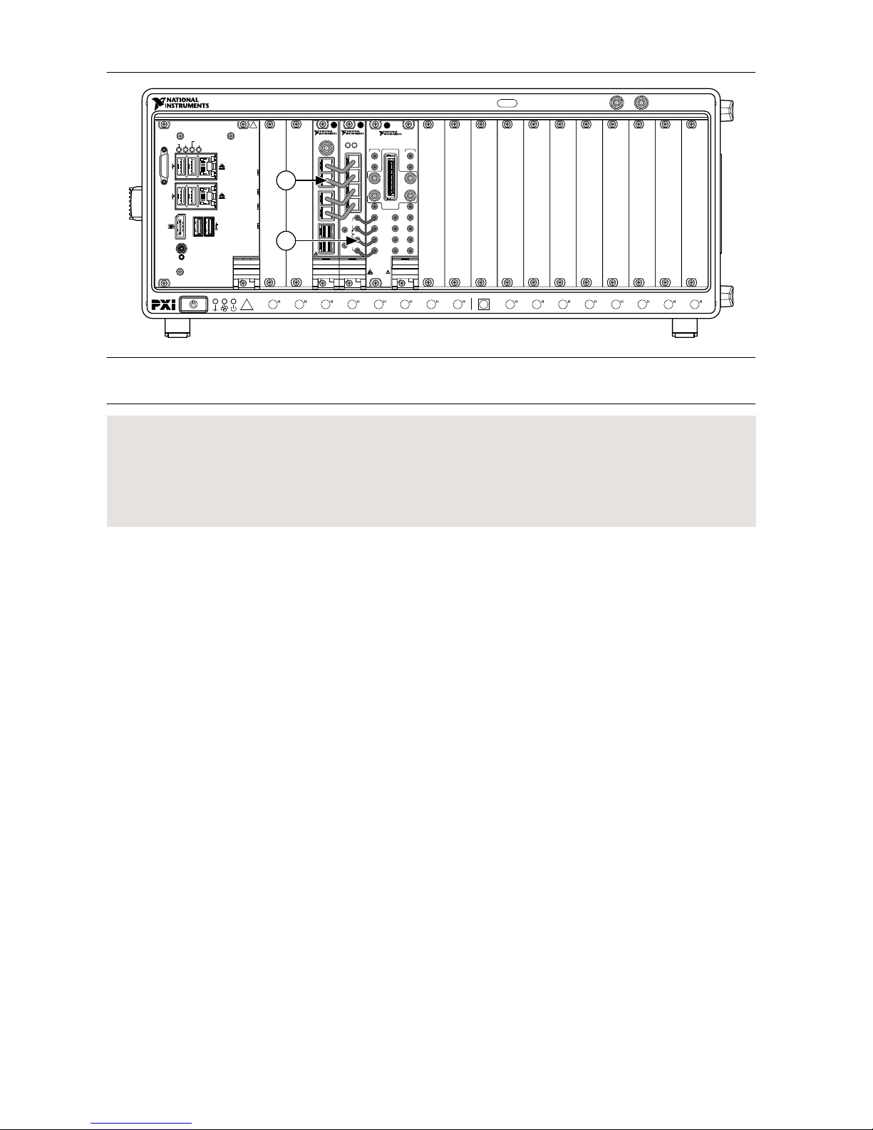
Figure 11. Unidirectional SISO (Baseband and IF) TX Chassis
213 4 5 6 7 8 9
11
12
13
14
15
16
17
18
10
NI PXIe-1085
10 MHz REF OUT IN
24 GB/s
Embedded Controller
RESET
TRIG
ACT/
LINK
ACT/
LINK
2
1
10/100
/1000
10/100
/1000
USER1
USER2
PWR OK/
FAULT
DRIVEGPIB
NI PXIe-3620
IF-LO Module, 2 GHz BW
TX
LO1
IN
LO1
IF OUT IF IN
IF SYNC INIF SYNC OUT
REF IN
REF OUT
LO2 OUT
ESD
SENSITIVE
LO2 IN
I+
I–
Q+
Q–
I+
I–
Q+
Q–
DIGITAL I/O
LVTTL
LO1
LO1
OUT
LO1
IN
LO1
OUT
RXmmWave
PXIe-7902
PORT
4
PORT
5
PORT
2
PORT
3
PORT
0
PORT
1
CLK
IN
PXIe-3610
I/Q Generator
0
1
2
3
REF IN
+10 dBm
NOM
+13 dBm
MAX
2 Vp-p
DIFF MAX
2 Vp-p
DIFF MAX
0 V
cm
ALL PORTS 50 Ω
REF
OUT
Q+
Q–
I+
I–
ACCESS ACTIVE
1
2
1. Mini-SAS HD(m)-to-Mini-SAS HD(m) (8.25 in.) Cables
2. MMPX(m)-to-MMPX(m) Cables
Related Information
Connecting mmRH-3642/3643/3652/3653 Radio Heads to a Unidirectional System on page
39
Connecting mmRH-3647/3657 Radio Heads to a Unidirectional System on page 42
Interconnecting the Unidirectional MIMO (Baseband) Modules
Complete the following steps to connect the modules of the unidirectional MIMO (baseband)
mmWave Transceiver System configuration.
1. Connect the adjoining PXIe-3630 and PXIe-7902 modules in the RX chassis using four
Mini-SAS HD(m)-to-Mini-SAS HD(m) (8.25 in.) cables.
a) Connect the 0 connector of the PXIe-3630 front panel to the PORT 0 connector of
the PXIe-7902 front panel.
b) Connect the 1 connector of the PXIe-3630 front panel to the PORT 1 connector of
the PXIe-7902 front panel.
c) Connect the 2 connector of the PXIe-3630 front panel to the PORT 2 connector of
the PXIe-7902 front panel.
d) Connect the 3 connector of the PXIe-3630 front panel to the PORT 3 connector of
the PXIe-7902 front panel.
mmWave Transceiver System Getting Started Guide | © National Instruments | 19
Page 20
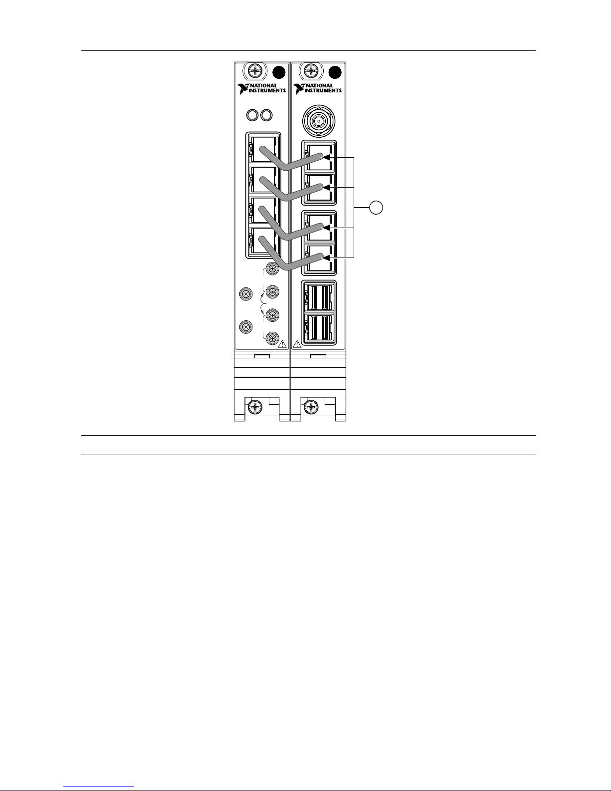
Figure 12. Interconnecting the PXIe-3630 and PXIe-7902 Modules
PXIe-3630
I/Q Digitizer
REF IN
+10 dBm
NOM
+13 dBm
MAX
1.5 Vp-p
DIFF MAX
1.5 Vp-p
DIFF MAX
0 V
cm
ALL PORTS 50 Ω
REF
OUT
0
1
2
3
Q+
Q–
I+
I–
ACCESS ACTIVE
PXIe-7902
CLK
IN
PORT
2
PORT
4
PORT
5
PORT
3
PORT
0
PORT
1
1
1. Mini-SAS HD(m)-to-Mini-SAS HD(m) (8.25 in.) Cables
2. Repeat step 1 to connect the second set of adjoining PXIe-3630 and PXIe-7902 modules
in the RX chassis.
3. Connect the PXIe-7902 modules in the RX chassis using three Mini-SAS HD(m)-toMini-SAS HD(m) (8.25 in.) cables.
a) Connect the PORT 4 connector of the PXIe-7902 front panel in slot 9 of the chassis
to the PORT 4 connector of the PXIe-7902 in slot 12 of the chassis.
b) Connect the PORT 5 connector of the PXIe-7902 front panel in slot 9 of the chassis
to the PORT 5 connector of the PXIe-7902 in slot 18 of the chassis.
c) Connect the PORT 5 connector of the PXIe-7902 front panel in slot 12 of the chassis
to the PORT 4 connector of the PXIe-7902 in slot 18 of the chassis.
20 | ni.com | mmWave Transceiver System Getting Started Guide
Page 21
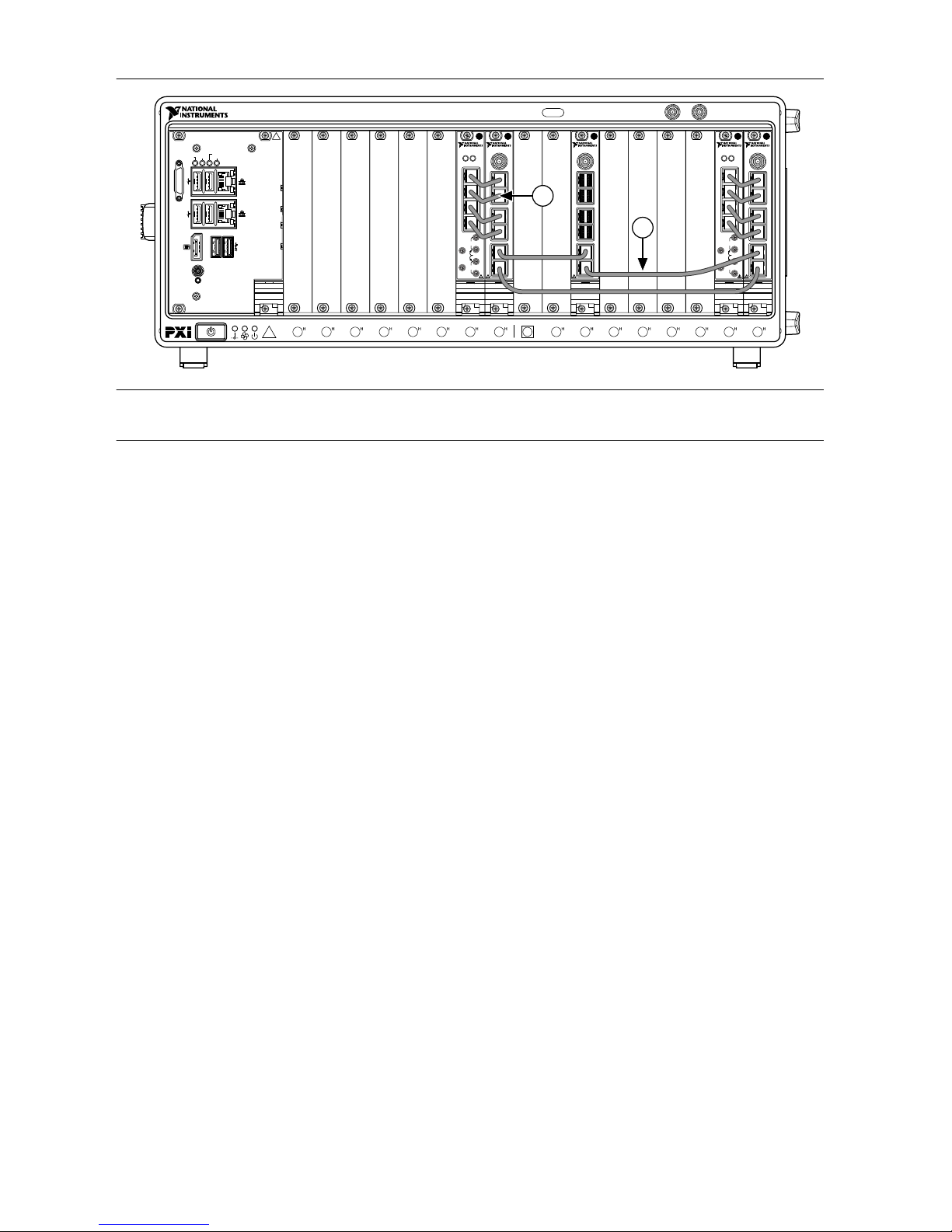
Figure 13. Unidirectional MIMO (Baseband) RX Chassis
PXIe-7902
CLK
IN
PORT
2
PORT
3
PORT
4
PORT
5
PORT
0
PORT
1
PXIe-3630
I/Q Digitizer
REF IN
+10 dBm
NOM
+13 dBm
MAX
1.5 Vp-p
DIFF MAX
1.5 Vp-p
DIFF MAX
0 V
cm
ALL PORTS 50 Ω
REF
OUT
0
1
2
3
Q+
Q–
I+
I–
ACCESS ACTIVE
PXIe-7902
CLK
IN
PORT
2
PORT
3
PORT
4
PORT
5
PORT
0
PORT
1
PXIe-3630
I/Q Digitizer
REF IN
+10 dBm
NOM
+13 dBm
MAX
1.5 Vp-p
DIFF MAX
1.5 Vp-p
DIFF MAX
0 V
cm
ALL PORTS 50 Ω
REF
OUT
0
1
2
3
Q+
Q–
I+
I–
ACCESS ACTIVE
213 4 5 6 7 8 9
11
12
13
14
15
16
17
18
10
NI PXIe-1085
10 MHz REF OUT IN
24 GB/s
PXIe-7902
CLK
IN
PORT
2
PORT
3
PORT
4
PORT
5
PORT
0
PORT
1
Embedded Controller
RESET
TRIG
ACT/
LINK
ACT/
LINK
2
1
10/100
/1000
10/100
/1000
USER1
USER2
PWR OK/
FAULT
DRIVEGPIB
1
2
1. Mini-SAS HD(m)-to-Mini-SAS HD(m) (8.25 in.) Cables
2. Mini-SAS HD(m)-to-Mini-SAS HD(m) (8.25 in.) Cables
4. Connect the adjoining PXIe-7902 and PXIe-3610 modules in the TX chassis using four
Mini-SAS HD(m)-to-Mini-SAS HD(m) (8.25 in.) cables.
a) Connect the PORT 0 connector of the PXIe-7902 front panel to the 0 connector of
the PXIe-3610 front panel.
b) Connect the PORT 1 connector of the PXIe-7902 front panel to the 1 connector of
the PXIe-3610 front panel.
c) Connect the PORT 2 connector of the PXIe-7902 front panel to the 2 connector of
the PXIe-3610 front panel.
d) Connect the PORT 3 connector of the PXIe-7902 front panel to the 3 connector of
the PXIe-3610 front panel.
mmWave Transceiver System Getting Started Guide | © National Instruments | 21
Page 22

Figure 14. Interconnecting the PXIe-3630 and PXIe-7902 Modules
PXIe-3630
I/Q Digitizer
REF IN
+10 dBm
NOM
+13 dBm
MAX
1.5 Vp-p
DIFF MAX
1.5 Vp-p
DIFF MAX
0 V
cm
ALL PORTS 50 Ω
REF
OUT
0
1
2
3
Q+
Q–
I+
I–
ACCESS ACTIVE
PXIe-7902
CLK
IN
PORT
2
PORT
4
PORT
5
PORT
3
PORT
0
PORT
1
1
1. Mini-SAS HD(m)-to-Mini-SAS HD(m) (8.25 in.) Cables
5. Repeat step 4 to connect the second set of adjoining PXIe-7902 and PXIe-3610 modules
in the TX chassis.
22 | ni.com | mmWave Transceiver System Getting Started Guide
Page 23
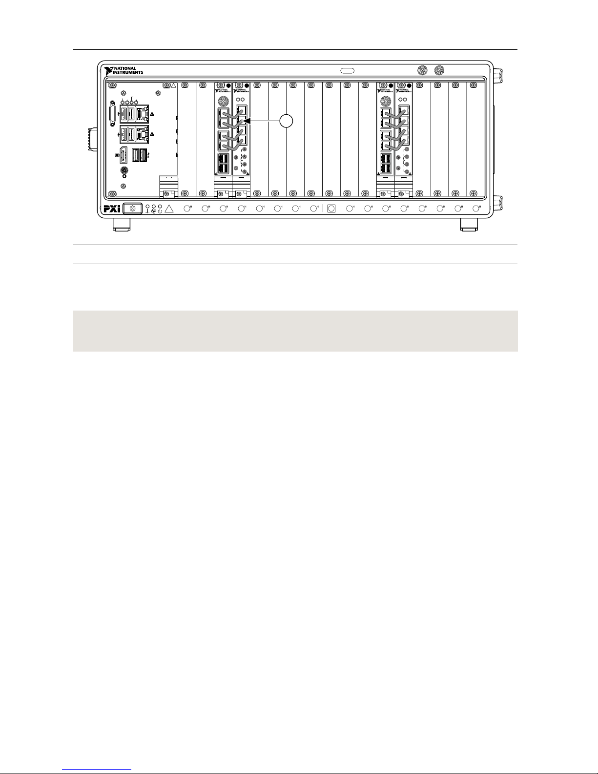
Figure 15. Unidirectional MIMO (Baseband) TX Chassis
213 4 5 6 7 8 9
11
12
13
14
15
16
17
18
10
NI PXIe-1085
10 MHz REF OUT IN
24 GB/s
Embedded Controller
RESET
TRIG
ACT/
LINK
ACT/
LINK
2
1
10/100
/1000
10/100
/1000
USER1
USER2
PWR OK/
FAULT
DRIVEGPIB
PXIe-7902
PORT
4
PORT
5
PORT
2
PORT
3
PORT
0
PORT
1
CLK
IN
PXIe-3610
I/Q Generator
0
1
2
3
REF IN
+10 dBm
NOM
+13 dBm
MAX
2 Vp-p
DIFF MAX
2 Vp-p
DIFF MAX
0 V
cm
ALL PORTS 50 Ω
REF
OUT
Q+
Q–
I+
I–
ACCESS ACTIVE
PXIe-7902
PORT
4
PORT
5
PORT
2
PORT
3
PORT
0
PORT
1
CLK
IN
PXIe-3610
I/Q Generator
0
1
2
3
REF IN
+10 dBm
NOM
+13 dBm
MAX
2 Vp-p
DIFF MAX
2 Vp-p
DIFF MAX
0 V
cm
ALL PORTS 50 Ω
REF
OUT
Q+
Q–
I+
I–
ACCESS ACTIVE
1
1. Mini-SAS HD(m)-to-Mini-SAS HD(m) (8.25 in.) Cables
Disconnect cables or otherwise attenuate the signal to ensure that no signal is entering the
baseband ports on the PXIe-3630 module during system startup.
Related Information
Configuring the Coding Modules of a MIMO System on page 50
Interconnecting the Unidirectional MIMO (Baseband and IF)
Modules
Complete the following steps to connect the modules of the unidirectional MIMO (baseband
and IF) mmWave Transceiver System configuration.
1. Connect one set of adjoining PXIe-3620 and PXIe-3630 modules in the RX chassis using
four MMPX(m)-to-MMPX(m) cables.
a) Connect the RX I+ connector of the PXIe-3620 front panel to the I+ connector of the
PXIe-3630 front panel.
b) Connect the RX I– connector of the PXIe-3620 front panel to the I– connector of the
PXIe-3630 front panel.
c) Connect the RX Q+ connector of the PXIe-3620 front panel to the Q+ connector of
the PXIe-3630 front panel.
d) Connect the RX Q– connector of the PXIe-3620 front panel to the Q– connector of
the PXIe-3630 front panel.
2. Connect the adjoining PXIe-3630 and PXIe-7902 modules in the RX chassis using four
Mini-SAS HD(m)-to-Mini-SAS HD(m) (8.25 in.) cables.
a) Connect the 0 connector of the PXIe-3630 front panel to the PORT 0 connector of
the PXIe-7902 front panel.
b) Connect the 1 connector of the PXIe-3630 front panel to the PORT 1 connector of
the PXIe-7902 front panel.
c) Connect the 2 connector of the PXIe-3630 front panel to the PORT 2 connector of
the PXIe-7902 front panel.
mmWave Transceiver System Getting Started Guide | © National Instruments | 23
Page 24

d) Connect the 3 connector of the PXIe-3630 front panel to the PORT 3 connector of
the PXIe-7902 front panel.
Figure 16. Interconnecting the PXIe-3620, PXIe-3630, and PXIe-7902 Modules
NI PXIe-3620
IF-LO Module, 2 GHz BW
TX
LO1
IN
LO1
IF OUT IF IN
IF SYNC INIF SYNC OUT
REF IN
REF OUT
LO2 OUT
ESD
SENSITIVE
LO2 IN
I+
I–
Q+
Q–
I+
I–
Q+
Q–
DIGITAL I/O
LVTTL
LO1
LO1
OUT
LO1
IN
LO1
OUT
RXmmWave
PXIe-3630
I/Q Digitizer
REF IN
+10 dBm
NOM
+13 dBm
MAX
1.5 Vp-p
DIFF MAX
1.5 Vp-p
DIFF MAX
0 V
cm
ALL PORTS 50 Ω
REF
OUT
0
1
2
3
Q+
Q–
I+
I–
ACCESS ACTIVE
PXIe-7902
CLK
IN
PORT
2
PORT
4
PORT
5
PORT
3
PORT
0
PORT
1
2
1
1. Mini-SAS HD(m)-to-Mini-SAS HD(m) (8.25 in.) Cables
2. MMPX(m)-to-MMPX(m) Cables
3. Repeat steps 1 and 2 to connect the second set of adjoining PXIe-3620, PXIe-3630, and
PXIe-7902 modules in the RX chassis.
4. Connect the PXIe-7902 modules in the RX chassis using three Mini-SAS HD(m)-toMini-SAS HD(m) (8.25 in.) cables.
a) Connect the PORT 4 connector of the PXIe-7902 front panel in slot 9 of the chassis
to the PORT 4 connector of the PXIe-7902 in slot 12 of the chassis.
b) Connect the PORT 5 connector of the PXIe-7902 front panel in slot 9 of the chassis
to the PORT 5 connector of the PXIe-7902 in slot 18 of the chassis.
c) Connect the PORT 5 connector of the PXIe-7902 front panel in slot 12 of the chassis
to the PORT 4 connector of the PXIe-7902 in slot 18 of the chassis.
24 | ni.com | mmWave Transceiver System Getting Started Guide
Page 25
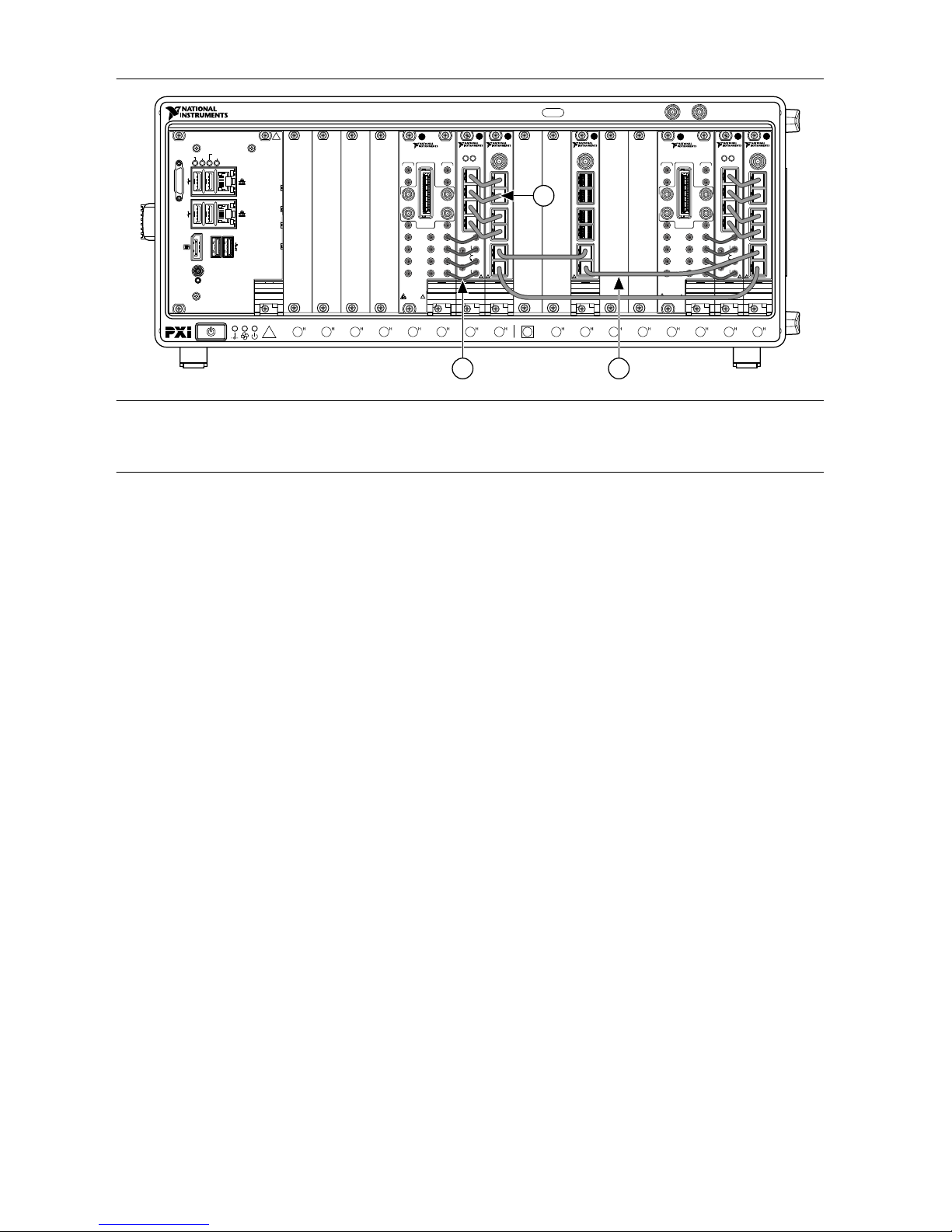
Figure 17. Unidirectional MIMO (Baseband and IF) RX Chassis
NI PXIe-3620
IF-LO Module, 2 GHz BW
TX
LO1
IN
LO1
IF OUT IF IN
IF SYNC INIF SYNC OUT
REF IN
REF OUT
LO2 OUT
ESD
SENSITIVE
LO2 IN
I+
I–
Q+
Q–
I+
I–
Q+
Q–
DIGITAL I/O
LVTTL
LO1
LO1
OUT
LO1
IN
LO1
OUT
RXmmWave
PXIe-7902
CLK
IN
PORT
2
PORT
3
PORT
4
PORT
5
PORT
0
PORT
1
PXIe-3630
I/Q Digitizer
REF IN
+10 dBm
NOM
+13 dBm
MAX
1.5 Vp-p
DIFF MAX
1.5 Vp-p
DIFF MAX
0 V
cm
ALL PORTS 50 Ω
REF
OUT
0
1
2
3
Q+
Q–
I+
I–
ACCESS ACTIVE
213 4 5 6 7 8 9
11
12
13
14
15
16
17
18
10
NI PXIe-1085
10 MHz REF OUT IN
24 GB/s
Embedded Controller
RESET
TRIG
ACT/
LINK
ACT/
LINK
2
1
10/100
/1000
10/100
/1000
USER1
USER2
PWR OK/
FAULT
DRIVEGPIB
PXIe-7902
CLK
IN
PORT
2
PORT
3
PORT
4
PORT
5
PORT
0
PORT
1
1
2 3
1. Mini-SAS HD(m)-to-Mini-SAS HD(m) (8.25 in.) Cables
2. MMPX(m)-to-MMPX(m) Cables
3. Mini-SAS HD(m)-to-Mini-SAS HD(m) (8.25 in.) Cables
5. Connect the adjoining PXIe-3610 and PXIe-3620 modules in the TX chassis using four
MMPX(m)-to-MMPX(m) cables.
a) Connect the I+ connector of the PXIe-3610 front panel to the TX I+ connector of the
PXIe-3620 front panel.
b) Connect the I– connector of the PXIe-3610 front panel to the TX I– connector of the
PXIe-3620 front panel.
c) Connect the Q+ connector of the PXIe-3610 front panel to the TX Q+ connector of
the PXIe-3620 front panel.
d) Connect the Q– connector of the PXIe-3610 front panel to the TX Q– connector of
the PXIe-3620 front panel.
6. Connect the adjoining PXIe-7902 and PXIe-3610 modules in the TX chassis using four
Mini-SAS HD(m)-to-Mini-SAS HD(m) (8.25 in.) cables.
a) Connect the PORT 0 connector of the PXIe-7902 front panel to the 0 connector of
the PXIe-3610 front panel.
b) Connect the PORT 1 connector of the PXIe-7902 front panel to the 1 connector of
the PXIe-3610 front panel.
c) Connect the PORT 2 connector of the PXIe-7902 front panel to the 2 connector of
the PXIe-3610 front panel.
d) Connect the PORT 3 connector of the PXIe-7902 front panel to the 3 connector of
the PXIe-3610 front panel.
mmWave Transceiver System Getting Started Guide | © National Instruments | 25
Page 26
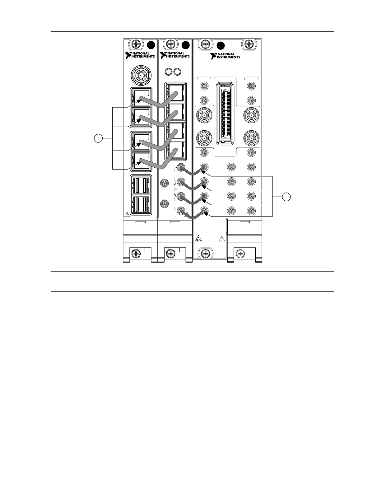
Figure 18. Interconnecting the PXIe-7902, PXIe-3610, and PXIe-3620 Modules
PXIe-3610
I/Q Generator
0
1
2
3
REF IN
+10 dBm
NOM
+13 dBm
MAX
2 Vp-p
DIFF MAX
2 Vp-p
DIFF MAX
0 V
cm
ALL PORTS 50 Ω
REF
OUT
Q+
Q–
I+
I–
ACCESS ACTIVE
PXIe-7902
PORT
4
PORT
5
PORT
2
PORT
3
PORT
0
PORT
1
CLK
IN
NI PXIe-3620
IF-LO Module, 2 GHz BW
TX
LO1
IN
LO1
IF OUT IF IN
IF SYNC INIF SYNC OUT
REF IN
REF OUT
LO2 OUT
ESD
SENSITIVE
LO2 IN
I+
I–
Q+
Q–
I+
I–
Q+
Q–
DIGITAL I/O
LVTTL
LO1
LO1
OUT
LO1
IN
LO1
OUT
RXmmWave
2
1
1. Mini-SAS HD(m)-to-Mini-SAS HD(m) (8.25 in.) Cables
2. MMPX(m)-to-MMPX(m) Cables
7. Repeat steps 5 and 6 to connect the second set of adjoining PXIe-7902, PXIe-3610,
PXIe-3620, and modules in the TX chassis.
26 | ni.com | mmWave Transceiver System Getting Started Guide
Page 27

Figure 19. Unidirectional MIMO (Baseband and IF) TX Chassis
213 4 5 6 7 8 9
11
12
13
14
15
16
17
18
10
NI PXIe-1085
10 MHz REF OUT IN
24 GB/s
Embedded Controller
RESET
TRIG
ACT/
LINK
ACT/
LINK
2
1
10/100
/1000
10/100
/1000
USER1
USER2
PWR OK/
FAULT
DRIVEGPIB
NI PXIe-3620
IF-LO Module, 2 GHz BW
TX
LO1
IN
LO1
IF OUT IF IN
IF SYNC INIF SYNC OUT
REF IN
REF OUT
LO2 OUT
ESD
SENSITIVE
LO2 IN
I+
I–
Q+
Q–
I+
I–
Q+
Q–
DIGITAL I/O
LVTTL
LO1
LO1
OUT
LO1
IN
LO1
OUT
RXmmWave
PXIe-7902
PORT
4
PORT
5
PORT
2
PORT
3
PORT
0
PORT
1
CLK
IN
PXIe-3610
I/Q Generator
0
1
2
3
REF IN
+10 dBm
NOM
+13 dBm
MAX
2 Vp-p
DIFF MAX
2 Vp-p
DIFF MAX
0 V
cm
ALL PORTS 50 Ω
REF
OUT
Q+
Q–
I+
I–
ACCESS ACTIVE
2
1
1. Mini-SAS HD(m)-to-Mini-SAS HD(m) (8.25 in.) Cables
2. MMPX(m)-to-MMPX(m) Cables
8. Repeat steps 1 through 6 for the second set of chassis.
Related Information
Connecting mmRH-3642/3643/3652/3653 Radio Heads to a Unidirectional System on page
39
Connecting mmRH-3647/3657 Radio Heads to a Unidirectional System on page 42
Configuring the Coding Modules of a MIMO System on page 50
Bidirectional System Setup
This section describes how to connect the modules of a bidirectional mmWave Transceiver
System.
Bidirectional mmWave Transceiver System configurations are as follows:
• Bidirectional SISO (baseband)
• Bidirectional SISO (baseband and IF)
• Bidirectional MIMO (baseband)
• Bidirectional MIMO (baseband and IF)
Each configuration consists of two RX/TX chassis with identical module configurations.
Interconnecting the Bidirectional SISO (Baseband) Modules
Complete the following steps to connect the modules of the bidirectional SISO (baseband)
mmWave Transceiver System configuration.
1. Connect the adjoining PXIe-7902 and PXIe-3610 modules using four Mini-SAS HD(m)to-Mini-SAS HD(m) (8.25 in.) cables.
a) Connect the PORT 0 connector of the PXIe-7902 front panel to the 0 connector of
the PXIe-3610 front panel.
mmWave Transceiver System Getting Started Guide | © National Instruments | 27
Page 28

b) Connect the PORT 1 connector of the PXIe-7902 front panel to the 1 connector of
the PXIe-3610 front panel.
c) Connect the PORT 2 connector of the PXIe-7902 front panel to the 2 connector of
the PXIe-3610 front panel.
d) Connect the PORT 3 connector of the PXIe-7902 front panel to the 3 connector of
the PXIe-3610 front panel.
Figure 20. Interconnecting the PXIe-7902 and PXIe-3610 Modules
PXIe-3610
I/Q Generator
PXIe-7902
0
1
2
3
REF IN
+10 dBm
NOM
+13 dBm
MAX
2 Vp-p
DIFF MAX
2 Vp-p
DIFF MAX
0 V
cm
ALL PORTS 50 Ω
REF
OUT
Q+
Q–
I+
I–
PORT
4
PORT
5
PORT
2
PORT
3
PORT
0
PORT
1
ACCESS ACTIVE
CLK
IN
1
1. Mini-SAS HD(m)-to-Mini-SAS HD(m) (8.25 in.) Cables
2. Connect the adjoining PXIe-3630 and PXIe-7902 modules using four Mini-SAS HD(m)to-Mini-SAS HD(m) (8.25 in.) cables.
a) Connect the 0 connector of the PXIe-3630 front panel to the PORT 0 connector of
the PXIe-7902 front panel.
b) Connect the 1 connector of the PXIe-3630 front panel to the PORT 1 connector of
the PXIe-7902 front panel.
c) Connect the 2 connector of the PXIe-3630 front panel to the PORT 2 connector of
the PXIe-7902 front panel.
d) Connect the 3 connector of the PXIe-3630 front panel to the PORT 3 connector of
the PXIe-7902 front panel.
3. Connect the PORT 4 connector of the PXIe-7902 front panel to the PORT 4 connector of
the second PXIe-7902 front panel.
28 | ni.com | mmWave Transceiver System Getting Started Guide
Page 29

Figure 21. Bidirectional SISO (Baseband) Chassis
PXIe-7902
CLK
IN
PORT
2
PORT
3
PORT
4
PORT
5
PORT
0
PORT
1
PXIe-3630
I/Q Digitizer
REF IN
+10 dBm
NOM
+13 dBm
MAX
1.5 Vp-p
DIFF MAX
1.5 Vp-p
DIFF MAX
0 V
cm
ALL PORTS 50 Ω
REF
OUT
0
1
2
3
Q+
Q–
I+
I–
ACCESS ACTIVE
213 4 5 6 7 8 9
11
12
13
14
15
16
17
18
10
NI PXIe-1085
10 MHz REF OUT IN
24 GB/s
Embedded Controller
RESET
TRIG
ACT/
LINK
ACT/
LINK
2
1
10/100
/1000
10/100
/1000
USER1
USER2
PWR OK/
FAULT
DRIVEGPIB
PXIe-7902
PORT
4
PORT
5
PORT
2
PORT
3
PORT
0
PORT
1
CLK
IN
PXIe-3610
I/Q Generator
0
1
2
3
REF IN
+10 dBm
NOM
+13 dBm
MAX
2 Vp-p
DIFF MAX
2 Vp-p
DIFF MAX
0 V
cm
ALL PORTS 50 Ω
REF
OUT
Q+
Q–
I+
I–
ACCESS ACTIVE
PXIe-7902
CLK
IN
PORT
2
PORT
3
PORT
4
PORT
5
PORT
0
PORT
1
2
1
1. Mini-SAS HD(m)-to-Mini-SAS HD(m) (8.25 in.) Cables
2. Mini-SAS HD(m)-to-Mini-SAS HD(m) (8.25 in.) Cable
4. Repeat steps 1 through 3 for the second RX/TX chassis.
Disconnect cables or otherwise attenuate the signal to ensure that no signal is entering the
baseband ports on the PXIe-3630 module during system startup.
Interconnecting the Bidirectional SISO (Baseband and IF)
Modules
Complete the following steps to connect the modules of the bidirectional SISO (baseband and
IF) mmWave Transceiver System configuration.
1. Connect the adjoining PXIe-3610 and PXIe-3620 modules using four MMPX(m)-toMMPX(m) cables.
a) Connect the I+ connector of the PXIe-3610 front panel to the TX I+ connector of the
PXIe-3620 front panel.
b) Connect the I– connector of the PXIe-3610 front panel to the TX I– connector of the
PXIe-3620 front panel.
c) Connect the Q+ connector of the PXIe-3610 front panel to the TX Q+ connector of
the PXIe-3620 front panel.
d) Connect the Q– connector of the PXIe-3610 front panel to the TX Q– connector of
the PXIe-3620 front panel.
2. Connect the adjoining PXIe-3620 and PXIe-3630 modules using four MMPX(m)-toMMPX(m) cables.
a) Connect the RX I+ connector of the PXIe-3620 front panel to the I+ connector of the
PXIe-3630 front panel.
b) Connect the RX I– connector of the PXIe-3620 front panel to the I– connector of the
PXIe-3630 front panel.
c) Connect the RX Q+ connector of the PXIe-3620 front panel to the Q+ connector of
the PXIe-3630 front panel.
d) Connect the RX Q– connector of the PXIe-3620 front panel to the Q– connector of
the PXIe-3630 front panel.
mmWave Transceiver System Getting Started Guide | © National Instruments | 29
Page 30

3. Connect the adjoining PXIe-7902 and PXIe-3610 modules using four Mini-SAS HD(m)to-Mini-SAS HD(m) (8.25 in.) cables.
a) Connect the PORT 0 connector of the PXIe-7902 front panel to the 0 connector of
the PXIe-3610 front panel.
b) Connect the PORT 1 connector of the PXIe-7902 front panel to the 1 connector of
the PXIe-3610 front panel.
c) Connect the PORT 2 connector of the PXIe-7902 front panel to the 2 connector of
the PXIe-3610 front panel.
d) Connect the PORT 3 connector of the PXIe-7902 front panel to the 3 connector of
the PXIe-3610 front panel.
4. Connect the adjoining PXIe-3630 and PXIe-7902 modules using four Mini-SAS HD(m)to-Mini-SAS HD(m) (8.25 in.) cables.
a) Connect the 0 connector of the PXIe-3630 front panel to the PORT 0 connector of
the PXIe-7902 front panel.
b) Connect the 1 connector of the PXIe-3630 front panel to the PORT 1 connector of
the PXIe-7902 front panel.
c) Connect the 2 connector of the PXIe-3630 front panel to the PORT 2 connector of
the PXIe-7902 front panel.
d) Connect the 3 connector of the PXIe-3630 front panel to the PORT 3 connector of
the PXIe-7902 front panel.
30 | ni.com | mmWave Transceiver System Getting Started Guide
Page 31

Figure 22. Interconnecting the PXIe-7902, PXIe-3610, PXIe-3620, PXIe-3630, and
PXIe-7902 Modules
PXIe-3610
I/Q Generator
PXIe-7902
0
1
2
3
REF IN
+10 dBm
NOM
+13 dBm
MAX
2 Vp-p
DIFF MAX
2 Vp-p
DIFF MAX
0 V
cm
ALL PORTS 50 Ω
REF
OUT
Q+
Q–
I+
I–
PORT
4
PORT
5
PORT
2
PORT
3
PORT
0
PORT
1
ACCESS ACTIVE
CLK
IN
NI PXIe-3620
IF-LO Module, 2 GHz BW
TX
LO1
IN
LO1
IF OUT IF IN
IF SYNC INIF SYNC OUT
REF IN
REF OUT
LO2 OUT
ESD
SENSITIVE
LO2 IN
I+
I–
Q+
Q–
I+
I–
Q+
Q–
DIGITAL I/O
LVTTL
LO1
LO1
OUT
LO1
IN
LO1
OUT
RXmmWave
PXIe-3630
I/Q Digitizer
REF IN
+10 dBm
NOM
+13 dBm
MAX
1.5 Vp-p
DIFF MAX
1.5 Vp-p
DIFF MAX
0 V
cm
ALL PORTS 50 Ω
REF
OUT
0
1
2
3
Q+
Q–
I+
I–
ACCESS ACTIVE
PXIe-7902
CLK
IN
PORT
2
PORT
3
PORT
4
PORT
5
PORT
0
PORT
1
2
1
1
1. Mini-SAS HD(m)-to-Mini-SAS HD(m) (8.25 in.) Cables
2. MMPX(m)-to-MMPX(m) Cables
5. Connect the PORT 4 connector of the PXIe-7902 front panel in the center of the chassis
to the PORT 4 connector of the PXIe-7902 front panel on the right side of the chassis.
mmWave Transceiver System Getting Started Guide | © National Instruments | 31
Page 32

Figure 23. Bidirectional SISO (Baseband and IF) Chassis
NI PXIe-3620
IF-LO Module, 2 GHz BW
TX
LO1
IN
LO1
IF OUT IF IN
IF SYNC INIF SYNC OUT
REF IN
REF OUT
LO2 OUT
ESD
SENSITIVE
LO2 IN
I+
I–
Q+
Q–
I+
I–
Q+
Q–
DIGITAL I/O
LVTTL
LO1
LO1
OUT
LO1
IN
LO1
OUT
RXmmWave
PXIe-7902
PORT
4
PORT
5
PORT
2
PORT
3
PORT
0
PORT
1
CLK
IN
PXIe-3610
I/Q Generator
0
1
2
3
REF IN
+10 dBm
NOM
+13 dBm
MAX
2 Vp-p
DIFF MAX
2 Vp-p
DIFF MAX
0 V
cm
ALL PORTS 50 Ω
REF
OUT
Q+
Q–
I+
I–
ACCESS ACTIVE
PXIe-7902
CLK
IN
PORT
2
PORT
3
PORT
4
PORT
5
PORT
0
PORT
1
PXIe-3630
I/Q Digitizer
REF IN
+10 dBm
NOM
+13 dBm
MAX
1.5 Vp-p
DIFF MAX
1.5 Vp-p
DIFF MAX
0 V
cm
ALL PORTS 50 Ω
REF
OUT
0
1
2
3
Q+
Q–
I+
I–
ACCESS ACTIVE
213 4 5 6 7 8 9
11
12
13
14
15
16
17
18
10
NI PXIe-1085
10 MHz REF OUT IN
24 GB/s
Embedded Controller
RESET
TRIG
ACT/
LINK
ACT/
LINK
2
1
10/100
/1000
10/100
/1000
USER1
USER2
PWR OK/
FAULT
DRIVEGPIB
PXIe-7902
CLK
IN
PORT
2
PORT
3
PORT
4
PORT
5
PORT
0
PORT
1
1
2
3
1. Mini-SAS HD(m)-to-Mini-SAS HD(m) (8.25 in.) Cables
2. MMPX(m)-to-MMPX(m) Cables
3. Mini-SAS HD(m)-to-Mini-SAS HD(m) (8.25 in.) Cable
6. Repeat steps 1 through 5 for the second RX/TX chassis.
Related Information
Connecting mmRH-3602/3603 Radio Heads to a Bidirectional System on page 44
Connecting mmRH-3642/3643/3652/3653 Radio Heads to a Bidirectional System on page 47
Connecting mmRH-3647/3657 Radio Heads to a Bidirectional System on page 49
Interconnecting the Bidirectional MIMO (Baseband) Modules
Complete the following steps to connect the modules of the bidirectional MIMO (baseband)
mmWave Transceiver System configuration.
1. Connect the adjoining PXIe-7902 and PXIe-3610 modules using four Mini-SAS HD(m)to-Mini-SAS HD(m) (8.25 in.) cables.
a) Connect the PORT 0 connector of the PXIe-7902 front panel to the 0 connector of
the PXIe-3610 front panel.
b) Connect the PORT 1 connector of the PXIe-7902 front panel to the 1 connector of
the PXIe-3610 front panel.
c) Connect the PORT 2 connector of the PXIe-7902 front panel to the 2 connector of
the PXIe-3610 front panel.
d) Connect the PORT 3 connector of the PXIe-7902 front panel to the 3 connector of
the PXIe-3610 front panel.
32 | ni.com | mmWave Transceiver System Getting Started Guide
Page 33

Figure 24. Interconnecting the PXIe-7902 and PXIe-3610 Modules
PXIe-3610
I/Q Generator
PXIe-7902
0
1
2
3
REF IN
+10 dBm
NOM
+13 dBm
MAX
2 Vp-p
DIFF MAX
2 Vp-p
DIFF MAX
0 V
cm
ALL PORTS 50 Ω
REF
OUT
Q+
Q–
I+
I–
PORT
4
PORT
5
PORT
2
PORT
3
PORT
0
PORT
1
ACCESS ACTIVE
CLK
IN
1
1. Mini-SAS HD(m)-to-Mini-SAS HD(m) (8.25 in.) Cables
2. Repeat step 1 to connect the second set of adjoining PXIe-7902 and PXIe-3610 modules.
3. Connect the adjoining PXIe-3630 and PXIe-7902 modules using four Mini-SAS HD(m)to-Mini-SAS HD(m) (8.25 in.) cables.
a) Connect the 0 connector of the PXIe-3630 front panel to the PORT 0 connector of
the PXIe-7902 front panel.
b) Connect the 1 connector of the PXIe-3630 front panel to the PORT 1 connector of
the PXIe-7902 front panel.
c) Connect the 2 connector of the PXIe-3630 front panel to the PORT 2 connector of
the PXIe-7902 front panel.
d) Connect the 3 connector of the PXIe-3630 front panel to the PORT 3 connector of
the PXIe-7902 front panel.
mmWave Transceiver System Getting Started Guide | © National Instruments | 33
Page 34

Figure 25. Interconnecting the PXIe-3630 and PXIe-7902 Modules
PXIe-3630
I/Q Digitizer
REF IN
+10 dBm
NOM
+13 dBm
MAX
1.5 Vp-p
DIFF MAX
1.5 Vp-p
DIFF MAX
0 V
cm
ALL PORTS 50 Ω
REF
OUT
0
1
2
3
Q+
Q–
I+
I–
ACCESS ACTIVE
PXIe-7902
CLK
IN
PORT
2
PORT
4
PORT
5
PORT
3
PORT
0
PORT
1
1
1. Mini-SAS HD(m)-to-Mini-SAS HD(m) (8.25 in.) Cables
4. Repeat step 3 to connect the second set of adjoining PXIe-3630 and PXIe-7902 modules.
5. Connect the PXIe-7902 modules in the chassis using three Mini-SAS HD(m)-to-MiniSAS HD(m) (8.25 in.) cables.
a) Connect the PORT 4 connector of the PXIe-7902 front panel in slot 9 of the chassis
to the PORT 4 connector of the PXIe-7902 in slot 12 of the chassis.
b) Connect the PORT 5 connector of the PXIe-7902 front panel in slot 9 of the chassis
to the PORT 5 connector of the PXIe-7902 in slot 18 of the chassis.
c) Connect the PORT 5 connector of the PXIe-7902 front panel in slot 12 of the chassis
to the PORT 4 connector of the PXIe-7902 in slot 18 of the chassis.
34 | ni.com | mmWave Transceiver System Getting Started Guide
Page 35

Figure 26. Bidirectional MIMO (Baseband) Chassis
PXIe-7902
PORT
4
PORT
5
PORT
2
PORT
3
PORT
0
PORT
1
CLK
IN
PXIe-3610
I/Q Generator
0
1
2
3
REF IN
+10 dBm
NOM
+13 dBm
MAX
2 Vp-p
DIFF MAX
2 Vp-p
DIFF MAX
0 V
cm
ALL PORTS 50 Ω
REF
OUT
Q+
Q–
I+
I–
ACCESS ACTIVE
PXIe-7902
PORT
4
PORT
5
PORT
2
PORT
3
PORT
0
PORT
1
CLK
IN
PXIe-3610
I/Q Generator
0
1
2
3
REF IN
+10 dBm
NOM
+13 dBm
MAX
2 Vp-p
DIFF MAX
2 Vp-p
DIFF MAX
0 V
cm
ALL PORTS 50 Ω
REF
OUT
Q+
Q–
I+
I–
ACCESS ACTIVE
PXIe-7902
CLK
IN
PORT
2
PORT
3
PORT
4
PORT
5
PORT
0
PORT
1
PXIe-3630
I/Q Digitizer
REF IN
+10 dBm
NOM
+13 dBm
MAX
1.5 Vp-p
DIFF MAX
1.5 Vp-p
DIFF MAX
0 V
cm
ALL PORTS 50 Ω
REF
OUT
0
1
2
3
Q+
Q–
I+
I–
ACCESS ACTIVE
PXIe-7902
CLK
IN
PORT
2
PORT
3
PORT
4
PORT
5
PORT
0
PORT
1
PXIe-3630
I/Q Digitizer
REF IN
+10 dBm
NOM
+13 dBm
MAX
1.5 Vp-p
DIFF MAX
1.5 Vp-p
DIFF MAX
0 V
cm
ALL PORTS 50 Ω
REF
OUT
0
1
2
3
Q+
Q–
I+
I–
ACCESS ACTIVE
213 4 5 6 7 8 9
11
12
13
14
15
16
17
18
10
NI PXIe-1085
10 MHz REF OUT IN
24 GB/s
Embedded Controller
RESET
TRIG
ACT/
LINK
ACT/
LINK
2
1
10/100
/1000
10/100
/1000
USER1
USER2
PWR OK/
FAULT
DRIVEGPIB
PXIe-7902
CLK
IN
PORT
2
PORT
3
PORT
4
PORT
5
PORT
0
PORT
1
1
2
1. Mini-SAS HD(m)-to-Mini-SAS HD(m) (8.25 in.) Cables
2. Mini-SAS HD(m)-to-Mini-SAS HD(m) (8.25 in.) Cables
6. Repeat steps 1 through 5 for the second RX/TX chassis.
Disconnect cables or otherwise attenuate the signal to ensure that no signal is entering the
baseband ports on the PXIe-3630 module during system startup.
Related Information
Configuring the Coding Modules of a MIMO System on page 50
Interconnecting the Bidirectional MIMO (Baseband and IF)
Modules
Complete the following steps to connect the modules of the bidirectional MIMO (baseband
and IF) mmWave Transceiver System configuration.
1. Connect the adjoining PXIe-3610 and PXIe-3620 modules using four MMPX(m)-toMMPX(m) cables.
a) Connect the I+ connector of the PXIe-3610 front panel to the TX I+ connector of the
PXIe-3620 front panel.
b) Connect the I– connector of the PXIe-3610 front panel to the TX I– connector of the
PXIe-3620 front panel.
c) Connect the Q+ connector of the PXIe-3610 front panel to the TX Q+ connector of
the PXIe-3620 front panel.
d) Connect the Q– connector of the PXIe-3610 front panel to the TX Q– connector of
the PXIe-3620 front panel.
2. Connect the adjoining PXIe-3620 and PXIe-3630 modules using four MMPX(m)-toMMPX(m) cables.
a) Connect the RX I+ connector of the PXIe-3620 front panel to the I+ connector of the
PXIe-3630 front panel.
b) Connect the RX I– connector of the PXIe-3620 front panel to the I– connector of the
PXIe-3630 front panel.
mmWave Transceiver System Getting Started Guide | © National Instruments | 35
Page 36

c) Connect the RX Q+ connector of the PXIe-3620 front panel to the Q+ connector of
the PXIe-3630 front panel.
d) Connect the RX Q– connector of the PXIe-3620 front panel to the Q– connector of
the PXIe-3630 front panel.
3. Connect the adjoining PXIe-7902 and PXIe-3610 modules using four Mini-SAS HD(m)to-Mini-SAS HD(m) (8.25 in.) cables.
a) Connect the PORT 0 connector of the PXIe-7902 front panel to the 0 connector of
the PXIe-3610 front panel.
b) Connect the PORT 1 connector of the PXIe-7902 front panel to the 1 connector of
the PXIe-3610 front panel.
c) Connect the PORT 2 connector of the PXIe-7902 front panel to the 2 connector of
the PXIe-3610 front panel.
d) Connect the PORT 3 connector of the PXIe-7902 front panel to the 3 connector of
the PXIe-3610 front panel.
4. Connect the adjoining PXIe-3630 and PXIe-7902 modules using four Mini-SAS HD(m)to-Mini-SAS HD(m) (8.25 in.) cables.
a) Connect the 0 connector of the PXIe-3630 front panel to the PORT 0 connector of
the PXIe-7902 front panel.
b) Connect the 1 connector of the PXIe-3630 front panel to the PORT 1 connector of
the PXIe-7902 front panel.
c) Connect the 2 connector of the PXIe-3630 front panel to the PORT 2 connector of
the PXIe-7902 front panel.
d) Connect the 3 connector of the PXIe-3630 front panel to the PORT 3 connector of
the PXIe-7902 front panel.
36 | ni.com | mmWave Transceiver System Getting Started Guide
Page 37

Figure 27. Interconnecting the PXIe-7902, PXIe-3610, PXIe-3620, PXIe-3630, and
PXIe-7902 Modules
PXIe-3610
I/Q Generator
PXIe-7902
0
1
2
3
REF IN
+10 dBm
NOM
+13 dBm
MAX
2 Vp-p
DIFF MAX
2 Vp-p
DIFF MAX
0 V
cm
ALL PORTS 50 Ω
REF
OUT
Q+
Q–
I+
I–
PORT
4
PORT
5
PORT
2
PORT
3
PORT
0
PORT
1
ACCESS ACTIVE
CLK
IN
NI PXIe-3620
IF-LO Module, 2 GHz BW
TX
LO1
IN
LO1
IF OUT IF IN
IF SYNC INIF SYNC OUT
REF IN
REF OUT
LO2 OUT
ESD
SENSITIVE
LO2 IN
I+
I–
Q+
Q–
I+
I–
Q+
Q–
DIGITAL I/O
LVTTL
LO1
LO1
OUT
LO1
IN
LO1
OUT
RXmmWave
PXIe-3630
I/Q Digitizer
REF IN
+10 dBm
NOM
+13 dBm
MAX
1.5 Vp-p
DIFF MAX
1.5 Vp-p
DIFF MAX
0 V
cm
ALL PORTS 50 Ω
REF
OUT
0
1
2
3
Q+
Q–
I+
I–
ACCESS ACTIVE
PXIe-7902
CLK
IN
PORT
2
PORT
3
PORT
4
PORT
5
PORT
0
PORT
1
2
1
1
1. Mini-SAS HD(m)-to-Mini-SAS HD(m) (8.25 in.) Cables
2. MMPX(m)-to-MMPX(m) Cables
5. Repeat steps 1 through 4 to connect the second set of adjoining PXIe-7902, PXIe-3610,
PXIe-3620, PXIe-3630, and PXIe-7902 modules.
6. Connect the PXIe-7902 modules in the chassis using three Mini-SAS HD(m)-to-MiniSAS HD(m) (8.25 in.) cables.
a) Connect the PORT 4 connector of the PXIe-7902 front panel in slot 9 of the chassis
to the PORT 4 connector of the PXIe-7902 in slot 12 of the chassis.
b) Connect the PORT 5 connector of the PXIe-7902 front panel in slot 9 of the chassis
to the PORT 5 connector of the PXIe-7902 in slot 18 of the chassis.
c) Connect the PORT 5 connector of the PXIe-7902 front panel in slot 12 of the chassis
to the PORT 4 connector of the PXIe-7902 in slot 18 of the chassis.
mmWave Transceiver System Getting Started Guide | © National Instruments | 37
Page 38

Figure 28. Bidirectional MIMO (Baseband and IF) Chassis
NI PXIe-3620
IF-LO Module, 2 GHz BW
TX
LO1
IN
LO1
IF OUT IF IN
IF SYNC INIF SYNC OUT
REF IN
REF OUT
LO2 OUT
ESD
SENSITIVE
LO2 IN
I+
I–
Q+
Q–
I+
I–
Q+
Q–
DIGITAL I/O
LVTTL
LO1
LO1
OUT
LO1
IN
LO1
OUT
RXmmWave
PXIe-7902
PORT
4
PORT
5
PORT
2
PORT
3
PORT
0
PORT
1
CLK
IN
PXIe-3610
I/Q Generator
0
1
2
3
REF IN
+10 dBm
NOM
+13 dBm
MAX
2 Vp-p
DIFF MAX
2 Vp-p
DIFF MAX
0 V
cm
ALL PORTS 50 Ω
REF
OUT
Q+
Q–
I+
I–
ACCESS ACTIVE
PXIe-7902
CLK
IN
PORT
2
PORT
3
PORT
4
PORT
5
PORT
0
PORT
1
PXIe-3630
I/Q Digitizer
REF IN
+10 dBm
NOM
+13 dBm
MAX
1.5 Vp-p
DIFF MAX
1.5 Vp-p
DIFF MAX
0 V
cm
ALL PORTS 50 Ω
REF
OUT
0
1
2
3
Q+
Q–
I+
I–
ACCESS ACTIVE
213 4 5 6 7 8 9
11
12
13
14
15
16
17
18
10
NI PXIe-1085
10 MHz REF OUT IN
24 GB/s
Embedded Controller
RESET
TRIG
ACT/
LINK
ACT/
LINK
2
1
10/100
/1000
10/100
/1000
USER1
USER2
PWR OK/
FAULT
DRIVEGPIB
PXIe-7902
CLK
IN
PORT
2
PORT
3
PORT
4
PORT
5
PORT
0
PORT
1
1
2 3
1. Mini-SAS HD(m)-to-Mini-SAS HD(m) (8.25 in.) Cables
2. MMPX(m)-to-MMPX(m) Cables
3. Mini-SAS HD(m)-to-Mini-SAS HD(m) (8.25 in.) Cables
7. Repeat steps 1 through 6 for the second RX/TX chassis.
Related Information
Connecting mmRH-3602/3603 Radio Heads to a Bidirectional System on page 44
Connecting mmRH-3642/3643/3652/3653 Radio Heads to a Bidirectional System on page 47
Connecting mmRH-3647/3657 Radio Heads to a Bidirectional System on page 49
Configuring the Coding Modules of a MIMO System on page 50
Connecting mmWave Radio Heads to the System
Recommended Torque
Ensure that connectors are torqued to the appropriate level when connecting mmWave radio
heads to the system.
38 | ni.com | mmWave Transceiver System Getting Started Guide
Page 39

Table 6. Recommended Connector Torque
Connector Type Recommended Torque
2.4 mm 0.9 N∙m (8 in.∙lb)
2.92 mm 0.9 N∙m (8 in.∙lb)
3.5 mm (SMA) 0.9 N∙m (8 in.∙lb)
Related Information
mmRH-3602 Front/Back Panel and LEDs on page 68
mmRH-3603 Front/Back Panel and LEDs on page 71
mmRH-3642 Front/Back Panel and LEDs on page 74
mmRH-3643 Front/Back Panel and LEDs on page 76
mmRH-3647 Front/Back Panel and LEDs on page 78
mmRH-3652 Front/Back Panel and LEDs on page 80
mmRH-3653 Front/Back Panel and LEDs on page 82
mmRH-3657 Front/Back Panel and LEDs on page 84
Connecting mmWave Radio Heads to a Unidirectional System
Connecting mmRH-3642/3643/3652/3653 Radio Heads to a Unidirectional
System
Complete the following steps to connect mmRH-3642/3643/3652/3653 radio heads to a
unidirectional mmWave Transceiver System.
Note Connect the modules of the mmWave Transceiver System for standard use
before connecting mmRH-3642/3643/3652/3653 radio heads.
1. Connect the RX chassis to the mmRH-3652/3653.
a) Connect the DIGITAL I/O connector of the PXIe-3620 front panel in the RX chassis
to the DIO adapter module using an EPLSP cable.
b) Connect the DIO adapter module to the DIO 1 connector1 of the mmRH-3652/3653
back panel using an HDMI(m)-to-mini-HDMI(m) cable.
c) Connect the RX LO1 connector of the PXIe-3620 front panel in the RX chassis to
the LO IN RX connector of the mmRH-3652/3653 back panel using an SMA(m)-toSMA(m) cable.
d) Connect the RX IF IN connector of the PXIe-3620 front panel in the RX chassis to
the IF OUT connector of the mmRH-3652/3653 back panel using an SMA(m)-toSMA(m) cable.
1
You may connect the DIO adapter module to the DIO 0 connector instead of the DIO 1 connector.
The choice of connector does not affect results.
mmWave Transceiver System Getting Started Guide | © National Instruments | 39
Page 40

Figure 29. Connecting the mmRH-3652/3653 to the Unidirectional SISO (Baseband and
IF) RX Chassis
NI PXIe-3620
IF-LO Module, 2 GHz BW
TX
LO1
IN
LO1
IF OUT IF IN
IF SYNC INIF SYNC OUT
REF IN
REF OUT
LO2 OUT
ESD
SENSITIVE
LO2 IN
I+
I–
Q+
Q–
I+
I–
Q+
Q–
DIGITAL I/O
LVTTL
LO1
LO1
OUT
LO1
IN
LO1
OUT
RXmmWave
PXIe-7902
CLK
IN
PORT
2
PORT
3
PORT
4
PORT
5
PORT
0
PORT
1
PXIe-3630
I/Q Digitizer
REF IN
+10 dBm
NOM
+13 dBm
MAX
1.5 Vp-p
DIFF MAX
1.5 Vp-p
DIFF MAX
0 V
cm
ALL PORTS 50 Ω
REF
OUT
0
1
2
3
Q+
Q–
I+
I–
ACCESS ACTIVE
213 4 5 6 7 8 9
11
12
13
14
15
16
17
18
10
NI PXIe-1085
10 MHz REF OUT IN
24 GB/s
Embedded Controller
RESET
TRIG
ACT/
LINK
ACT/
LINK
2
1
10/100
/1000
10/100
/1000
USER1
USER2
PWR OK/
FAULT
DRIVEGPIB
PXIe-7902
CLK
IN
PORT
2
PORT
3
PORT
4
PORT
5
PORT
0
PORT
1
7
54
1
2
3
8
6
LO IN RX
IF OUT
+12 dBm MAX
DIO 1 DIO 0
ACTIVE ACCESS
50Ω
Coupling Torque
90 N-cm / 8 lbf-in
Input Damage Level
LO: +9 dBm
12 V 2.5A MAX
1. Mini-SAS HD(m)-to-Mini-SAS HD(m) (8.25 in.)
Cables
2. MMPX(m)-to-MMPX(m) Cables
3. Mini-SAS HD(m)-to-Mini-SAS HD(m) (8.25 in.)
Cable
4. SMA(m)-to-SMA(m) Cable
5. SMA(m)-to-SMA(m) Cable
6. EPLSP Cable
7. DIO Adapter Module
8. HDMI(m)-to-mini-HDMI(m) Cable
e) If you have a MIMO system, repeat steps a through d for the second PXIe-3620
module in the RX chassis and a second mmRH-3652/3653.
2. Connect the TX chassis to the mmRH-3642/3643.
a) Connect the DIGITAL I/O connector of the PXIe-3620 front panel in the TX chassis
to the DIO adapter module using an EPLSP cable.
b) Connect the DIO adapter module to the DIO 1 connector2 of the mmRH-3642/3643
back panel using an HDMI(m)-to-mini-HDMI(m) cable.
c) Connect the TX LO1 connector of the PXIe-3620 front panel in the TX chassis to
the LO IN TX connector of the mmRH-3642/3643 back panel using an SMA(m)-toSMA(m) cable.
2
You may connect the DIO adapter module to the DIO 0 connector instead of the DIO 1 connector.
The choice of connector does not affect results.
40 | ni.com | mmWave Transceiver System Getting Started Guide
Page 41

d) Connect the TX IF OUT connector of the PXIe-3620 front panel in the TX chassis to
the IF IN connector of the mmRH-3642/3643 back panel using an SMA(m)-toSMA(m) cable.
Figure 30. Connecting the mmRH-3642/3643 to the Unidirectional SISO (Baseband and
IF) TX Chassis
LO IN TX
IF IN
0 dBm MAX
DIO 1 DIO 0
ACTIVE ACCESS
50Ω
Coupling Torque
90 N-cm / 8 lbf-in
Input Damage Level
LO: +9 dBm
12 V 2.5A MAX
213 4 5 6 7 8 9
11
12
13
14
15
16
17
18
10
NI PXIe-1085
10 MHz REF OUT IN
24 GB/s
Embedded Controller
RESET
TRIG
ACT/
LINK
ACT/
LINK
2
1
10/100
/1000
10/100
/1000
USER1
USER2
PWR OK/
FAULT
DRIVEGPIB
NI PXIe-3620
IF-LO Module, 2 GHz BW
TX
LO1
IN
LO1
IF OUT IF IN
IF SYNC INIF SYNC OUT
REF IN
REF OUT
LO2 OUT
ESD
SENSITIVE
LO2 IN
I+
I–
Q+
Q–
I+
I–
Q+
Q–
DIGITAL I/O
LVTTL
LO1
LO1
OUT
LO1
IN
LO1
OUT
RXmmWave
PXIe-7902
PORT
4
PORT
5
PORT
2
PORT
3
PORT
0
PORT
1
CLK
IN
PXIe-3610
I/Q Generator
0
1
2
3
REF IN
+10 dBm
NOM
+13 dBm
MAX
2 Vp-p
DIFF MAX
2 Vp-p
DIFF MAX
0 V
cm
ALL PORTS 50 Ω
REF
OUT
Q+
Q–
I+
I–
ACCESS ACTIVE
5
6
7
1
2
3
4
1. Mini-SAS HD(m)-to-Mini-SAS HD(m) (8.25 in.)
Cables
2. MMPX(m)-to-MMPX(m) Cables
3. SMA(m)-to-SMA(m) Cable
4. SMA(m)-to-SMA(m) Cable
5. EPLSP Cable
6. DIO Adapter Module
7. HDMI(m)-to-mini-HDMI(m) Cable
e) If you have a MIMO system, repeat steps a through d for the second PXIe-3620
module in the TX chassis and a second mmRH-3642/3643.
mmWave Transceiver System Getting Started Guide | © National Instruments | 41
Page 42

3. Connect all mmWave radio heads to power.
Related Information
Interconnecting the Unidirectional MIMO (Baseband and IF) Modules on page 23
Interconnecting the Unidirectional SISO (Baseband and IF) Modules on page 15
Connecting mmRH-3647/3657 Radio Heads to a Unidirectional System
Complete the following steps to connect mmRH-3647/3657 radio heads to a unidirectional
mmWave Transceiver System.
Note Connect the modules of the mmWave Transceiver System for standard use
before connecting mmRH-3647/3657 radio heads.
1. Connect the RX chassis to the mmRH-3657.
a) Connect the DIGITAL I/O connector of the PXIe-3620 front panel in the RX chassis
to the CONTROL connector of the mmRH-3657 back panel using an EPLSP cable.
b) Connect the RX LO1 connector of the PXIe-3620 front panel in the RX chassis to
the LO IN connector of the mmRH-3657 back panel using an SMA(m)-to-SMA(m)
cable.
c) Connect the RX IF IN connector of the PXIe-3620 front panel in the RX chassis to
the IF OUT connector of the mmRH-3657 back panel using an SMA(m)-to-SMA(m)
cable.
42 | ni.com | mmWave Transceiver System Getting Started Guide
Page 43

Figure 31. Connecting the mmRH-3657 to the Unidirectional SISO (Baseband and IF)
RX Chassis
NI PXIe-3620
IF-LO Module, 2 GHz BW
TX
LO1
IN
LO1
IF OUT IF IN
IF SYNC INIF SYNC OUT
REF IN
REF OUT
LO2 OUT
ESD
SENSITIVE
LO2 IN
I+
I–
Q+
Q–
I+
I–
Q+
Q–
DIGITAL I/O
LVTTL
LO1
LO1
OUT
LO1
IN
LO1
OUT
RXmmWave
PXIe-7902
CLK
IN
PORT
2
PORT
3
PORT
4
PORT
5
PORT
0
PORT
1
PXIe-3630
I/Q Digitizer
REF IN
+10 dBm
NOM
+13 dBm
MAX
1.5 Vp-p
DIFF MAX
1.5 Vp-p
DIFF MAX
0 V
cm
ALL PORTS 50 Ω
REF
OUT
0
1
2
3
Q+
Q–
I+
I–
ACCESS ACTIVE
213 4 5 6 7 8 9
11
12
13
14
15
16
17
18
10
NI PXIe-1085
10 MHz REF OUT IN
24 GB/s
Embedded Controller
RESET
TRIG
ACT/
LINK
ACT/
LINK
2
1
10/100
/1000
10/100
/1000
USER1
USER2
PWR OK/
FAULT
DRIVEGPIB
PXIe-7902
CLK
IN
PORT
2
PORT
3
PORT
4
PORT
5
PORT
0
PORT
1
CONTROLLO IN
ACCESS
Input Damage Levels:
LO: +12 dBm
IF: –20 dBm
IF OUT
ACTIVE
2A MAX
12 V
5
1
2 3
4
1. Mini-SAS HD(m)-to-Mini-SAS HD(m) (8.25 in.)
Cables
2. MMPX(m)-to-MMPX(m) Cables
3. Mini-SAS HD(m)-to-Mini-SAS HD(m) (8.25 in.)
Cable
4. SMA(m)-to-SMA(m) Cables
5. EPLSP Cable
d) If you have a MIMO system, repeat steps a through c for the second PXIe-3620
module in the RX chassis and a second mmRH-3657.
2. Connect the TX chassis to the mmRH-3647.
a) Connect the DIGITAL I/O connector of the PXIe-3620 front panel in the TX chassis
to the CONTROL connector of the mmRH-3647 back panel using an EPLSP cable.
b) Connect the TX LO1 connector of the PXIe-3620 front panel in the TX chassis to
the LO IN connector of the mmRH-3647 back panel using an SMA(m)-to-SMA(m)
cable.
c) Connect the TX IF OUT connector of the PXIe-3620 front panel in the TX chassis to
the IF IN connector of the mmRH-3647 back panel using an SMA(m)-to-SMA(m)
cable.
mmWave Transceiver System Getting Started Guide | © National Instruments | 43
Page 44

Figure 32. Connecting the mmRH-3647 to the Unidirectional SISO (Baseband and IF)
TX Chassis
213 4 5 6 7 8 9
11
12
13
14
15
16
17
18
10
NI PXIe-1085
10 MHz REF OUT IN
24 GB/s
Embedded Controller
RESET
TRIG
ACT/
LINK
ACT/
LINK
2
1
10/100
/1000
10/100
/1000
USER1
USER2
PWR OK/
FAULT
DRIVEGPIB
NI PXIe-3620
IF-LO Module, 2 GHz BW
TX
LO1
IN
LO1
IF OUT IF IN
IF SYNC INIF SYNC OUT
REF IN
REF OUT
LO2 OUT
ESD
SENSITIVE
LO2 IN
I+
I–
Q+
Q–
I+
I–
Q+
Q–
DIGITAL I/O
LVTTL
LO1
LO1
OUT
LO1
IN
LO1
OUT
RXmmWave
PXIe-7902
PORT
4
PORT
5
PORT
2
PORT
3
PORT
0
PORT
1
CLK
IN
PXIe-3610
I/Q Generator
0
1
2
3
REF IN
+10 dBm
NOM
+13 dBm
MAX
2 Vp-p
DIFF MAX
2 Vp-p
DIFF MAX
0 V
cm
ALL PORTS 50 Ω
REF
OUT
Q+
Q–
I+
I–
ACCESS ACTIVE
CONTROLLO IN
ACCESS
Input Damage Levels:
LO: +12 dBm
IF: –20 dBm
IF IN
ACTIVE
2A MAX
12 V
1
2
3
4
1. Mini-SAS HD(m)-to-Mini-SAS HD(m) (8.25 in.)
Cables
2. MMPX(m)-to-MMPX(m) Cables
3. SMA(m)-to-SMA(m) Cables
4. EPLSP Cable
d) If you have a MIMO system, repeat steps a through c for the second PXIe-3620
module in the TX chassis and a second mmRH-3647.
3. Connect all mmWave radio heads to power.
Related Information
Assembling mmWave Radio Head Tripods (mmRH-3647/3657) on page 7
Interconnecting the Unidirectional SISO (Baseband and IF) Modules on page 15
Interconnecting the Unidirectional MIMO (Baseband and IF) Modules on page 23
Connecting mmWave Radio Heads to a Bidirectional System
Connecting mmRH-3602/3603 Radio Heads to a Bidirectional System
Complete the following steps to connect mmRH-3602/3603 radio heads to a bidirectional
mmWave Transceiver System.
Note Connect the modules of the mmWave Transceiver System for standard use
before connecting mmRH-3602/3603 radio heads.
44 | ni.com | mmWave Transceiver System Getting Started Guide
Page 45

1. Connect the DIGITAL I/O connector of the PXIe-3620 front panel to the DIO adapter
module using an EPLSP cable.
2. Connect the DIO adapter module to the DIO 1 connector3 of the mmRH-3602/3603 back
panel using an HDMI(m)-to-mini-HDMI(m) cable.
3. Connect the RX LO1 connector of the PXIe-3620 front panel to the LO IN RX connector
of the mmRH-3602/3603 back panel using an SMA(m)-to-SMA(m) cable.
4. Connect the RX IF IN connector of the PXIe-3620 front panel to the IF OUT connector
of the mmRH-3602/3603 back panel using an SMA(m)-to-SMA(m) cable.
5. Connect the TX LO1 connector of the PXIe-3620 front panel to the LO IN TX connector
of the mmRH-3602/3603 back panel using an SMA(m)-to-SMA(m) cable.
6. Connect the TX IF OUT connector of the PXIe-3620 front panel to the IF IN connector of
the mmRH-3602/3603 back panel using an SMA(m)-to-SMA(m) cable.
3
You may connect the DIO adapter module to the DIO 0 connector instead of the DIO 1 connector.
The choice of connector does not affect results.
mmWave Transceiver System Getting Started Guide | © National Instruments | 45
Page 46

Figure 33. Connecting the mmRH-3602/3603 to the Bidirectional SISO (Baseband and
IF) System
NI PXIe-3620
IF-LO Module, 2 GHz BW
TX
LO1
IN
LO1
IF OUT IF IN
IF SYNC INIF SYNC OUT
REF IN
REF OUT
LO2 OUT
ESD
SENSITIVE
LO2 IN
I+
I–
Q+
Q–
I+
I–
Q+
Q–
DIGITAL I/O
LVTTL
LO1
LO1
OUT
LO1
IN
LO1
OUT
RXmmWave
PXIe-7902
PORT
4
PORT
5
PORT
2
PORT
3
PORT
0
PORT
1
CLK
IN
PXIe-3610
I/Q Generator
0
1
2
3
REF IN
+10 dBm
NOM
+13 dBm
MAX
2 Vp-p
DIFF MAX
2 Vp-p
DIFF MAX
0 V
cm
ALL PORTS 50 Ω
REF
OUT
Q+
Q–
I+
I–
ACCESS ACTIVE
PXIe-7902
CLK
IN
PORT
2
PORT
3
PORT
4
PORT
5
PORT
0
PORT
1
PXIe-3630
I/Q Digitizer
REF IN
+10 dBm
NOM
+13 dBm
MAX
1.5 Vp-p
DIFF MAX
1.5 Vp-p
DIFF MAX
0 V
cm
ALL PORTS 50 Ω
REF
OUT
0
1
2
3
Q+
Q–
I+
I–
ACCESS ACTIVE
213 4 5 6 7 8 9
11
12
13
14
15
16
17
1810
NI PXIe-1085
10 MHz REF OUT IN
24 GB/s
Embedded Controller
RESET
TRIG
ACT/
LINK
ACT/
LINK
2
1
10/100
/1000
10/100
/1000
USER1
USER2
PWR OK/
FAULT
DRIVEGPIB
PXIe-7902
CLK
IN
PORT
2
PORT
3
PORT
4
PORT
5
PORT
0
PORT
1
LO IN RX
LO IN TX
IF OUT
IF IN
+12 dBm MAX
0 dBm MAX
DIO 1
DIO 0
ACTIVE ACCESS
50Ω
Coupling Torque
90 N-cm / 8 lbf-in
Input Damage Level
LO: +9 dBm
12 V 2.5A MAX
8
10
1
2 3
65
4
7
9
1. Mini-SAS HD(m)-to-Mini-SAS HD(m) (8.25 in.)
Cables
2. MMPX(m)-to-MMPX(m) Cables
3. Mini-SAS HD(m)-to-Mini-SAS HD(m) (8.25 in.)
Cable
4. SMA(m)-to-SMA(m) Cable
5. SMA(m)-to-SMA(m) Cable
6. SMA(m)-to-SMA(m) Cable
7. SMA(m)-to-SMA(m) Cable
8. EPLSP Cable
9. DIO Adapter Module
10. HDMI(m)-to-mini-HDMI(m) Cable
7. If you have a MIMO system, repeat steps 1 through 6 for the second PXIe-3620,
PXIe-3610, and PXIe-3630 modules in the chassis, as well as an additional
mmRH-3602/3603.
8. Repeat steps 1 through 8 for the second RX/TX chassis.
46 | ni.com | mmWave Transceiver System Getting Started Guide
Page 47

9. Connect all mmWave radio heads to power.
Related Information
Interconnecting the Bidirectional MIMO (Baseband and IF) Modules on page 35
Interconnecting the Bidirectional SISO (Baseband and IF) Modules on page 29
Connecting mmRH-3642/3643/3652/3653 Radio Heads to a Bidirectional
System
Complete the following steps to connect mmRH-3642/3643/3652/3653 radio heads to a
bidirectional mmWave Transceiver System.
Note Connect the modules of the mmWave Transceiver System for standard use
before connecting mmRH-3642/3643/3652/3653 radio heads.
1. Connect to the DIGITAL I/O connector of the PXIe-3620 front panel using the joint end
of a dual-channel EPLSP cable.
2. Connect the DIO adapter module to the DIO 1 connector4 of the mmRH-3652/3653 back
panel using an HDMI(m)-to-mini-HDMI(m) cable.
3. Connect the other DIO adapter module to the DIO 1 connector4 of the mmRH-3642/3643
back panel using an HDMI(m)-to-mini-HDMI(m) cable.
4. Connect the RX LO1 connector of the PXIe-3620 front panel to the LO IN RX connector
of the mmRH-3652/3653 back panel using an SMA(m)-to-SMA(m) cable.
5. Connect the RX IF IN connector of the PXIe-3620 front panel to the IF OUT connector
of the mmRH-3652/3653 back panel using an SMA(m)-to-SMA(m) cable.
6. Connect the TX LO1 connector of the PXIe-3620 front panel to the LO IN TX connector
of the mmRH-3642/3643 back panel using an SMA(m)-to-SMA(m) cable.
7. Connect the TX IF OUT connector of the PXIe-3620 front panel to the IF IN connector of
the mmRH-3642/3643 back panel using an SMA(m)-to-SMA(m) cable.
4
You may connect the DIO adapter module to the DIO 0 connector instead of the DIO 1 connector.
The choice of connector does not affect results.
mmWave Transceiver System Getting Started Guide | © National Instruments | 47
Page 48

Figure 34. Connecting the mmRH-3642/3643/3652/3653 to the Bidirectional SISO
(Baseband and IF) System
LO IN TX
IF IN
0 dBm MAX
DIO 1 DIO 0
ACTIVE ACCESS
50Ω
Coupling Torque
90 N-cm / 8 lbf-in
Input Damage Level
LO: +9 dBm
LO IN RX
IF OUT
+12 dBm MAX
DIO 1 DIO 0
ACTIVE ACCESS
50Ω
Coupling Torque
90 N-cm / 8 lbf-in
Input Damage Level
LO: +9 dBm
12 V 2.5A MAX
NI PXIe-3620
IF-LO Module, 2 GHz BW
TX
LO1
IN
LO1
IF OUT IF IN
IF SYNC INIF SYNC OUT
REF IN
REF OUT
LO2 OUT
ESD
SENSITIVE
LO2 IN
I+
I–
Q+
Q–
I+
I–
Q+
Q–
DIGITAL I/O
LVTTL
LO1
LO1
OUT
LO1
IN
LO1
OUT
RXmmWave
PXIe-7902
PORT
4
PORT
5
PORT
2
PORT
3
PORT
0
PORT
1
CLK
IN
PXIe-3610
I/Q Generator
0
1
2
3
REF IN
+10 dBm
NOM
+13 dBm
MAX
2 Vp-p
DIFF MAX
2 Vp-p
DIFF MAX
0 V
cm
ALL PORTS 50 Ω
REF
OUT
Q+
Q–
I+
I–
ACCESS ACTIVE
PXIe-7902
CLK
IN
PORT
2
PORT
3
PORT
4
PORT
5
PORT
0
PORT
1
PXIe-3630
I/Q Digitizer
REF IN
+10 dBm
NOM
+13 dBm
MAX
1.5 Vp-p
DIFF MAX
1.5 Vp-p
DIFF MAX
0 V
cm
ALL PORTS 50 Ω
REF
OUT
0
1
2
3
Q+
Q–
I+
I–
ACCESS ACTIVE
213 4 5 6 7 8 9
11
12
13
14
15
16
17
1810
NI PXIe-1085
10 MHz REF OUT IN
24 GB/s
Embedded Controller
RESET
TRIG
ACT/
LINK
ACT/
LINK
2
1
10/100
/1000
10/100
/1000
USER1
USER2
PWR OK/
FAULT
DRIVEGPIB
PXIe-7902
CLK
IN
PORT
2
PORT
3
PORT
4
PORT
5
PORT
0
PORT
1
8
1
32
7
4
6
5
1. Mini-SAS HD(m)-to-Mini-SAS HD(m) (8.25 in.)
Cables
2. MMPX(m)-to-MMPX(m) Cables
3. Mini-SAS HD(m)-to-Mini-SAS HD(m) (8.25 in.)
Cable
4. SMA(m)-to-SMA(m) Cable
5. SMA(m)-to-SMA(m) Cable
6. EPLSP Cable
7. DIO Adapter Module
8. HDMI(m)-to-mini-HDMI(m) Cable
8. If you have a MIMO system, repeat steps 1 through 7 for the second PXIe-3620,
PXIe-3610, and PXIe-3630 modules in the chassis, as well as an additional
mmRH-3642/3643 and mmRH-3652/3653.
9. Repeat steps 1 through 8 for the second RX/TX chassis.
10. Connect all mmWave radio heads to power.
Related Information
Interconnecting the Bidirectional MIMO (Baseband and IF) Modules on page 35
Interconnecting the Bidirectional SISO (Baseband and IF) Modules on page 29
48 | ni.com | mmWave Transceiver System Getting Started Guide
Page 49

Connecting mmRH-3647/3657 Radio Heads to a Bidirectional System
Complete the following steps to connect mmRH-3647/3657 mmWave radio heads to a
bidirectional mmWave Transceiver System.
Note Connect the modules of the mmWave Transceiver System for standard use
before connecting mmRH-3647/3657 radio heads.
1. Connect to the DIGITAL I/O connector of the PXIe-3620 front panel using the joint end
of a dual-channel EPLSP cable.
2. Connect one end of the dual-channel EPLSP cable to the CONTROL connector of the
mmRH-3657 back panel.
3. Connect the other end of the dual-channel EPLSP cable to the CONTROL connector of
the mmRH-3647 back panel.
4. Connect the RX LO1 connector of the PXIe-3620 front panel to the LO IN connector of
the mmRH-3657 back panel using an SMA(m)-to-SMA(m) cable.
5. Connect the RX IF IN connector of the PXIe-3620 front panel to the IF OUT connector
of the mmRH-3657 back panel using an SMA(m)-to-SMA(m) cable.
6. Connect the TX LO1 connector of the PXIe-3620 front panel to the LO IN connector of
the mmRH-3647 back panel using an SMA(m)-to-SMA(m) cable.
7. Connect the TX IF OUT connector of the PXIe-3620 front panel to the IF IN connector of
the mmRH-3647 back panel using an SMA(m)-to-SMA(m) cable.
mmWave Transceiver System Getting Started Guide | © National Instruments | 49
Page 50

Figure 35. Connecting mmWave Heads to the Bidirectional SISO (Baseband and IF)
System
NI PXIe-3620
IF-LO Module, 2 GHz BW
TX
LO1
IN
LO1
IF OUT IF IN
IF SYNC INIF SYNC OUT
REF IN
REF OUT
LO2 OUT
ESD
SENSITIVE
LO2 IN
I+
I–
Q+
Q–
I+
I–
Q+
Q–
DIGITAL I/O
LVTTL
LO1
LO1
OUT
LO1
IN
LO1
OUT
RXmmWave
PXIe-7902
PORT
4
PORT
5
PORT
2
PORT
3
PORT
0
PORT
1
CLK
IN
PXIe-3610
I/Q Generator
0
1
2
3
REF IN
+10 dBm
NOM
+13 dBm
MAX
2 Vp-p
DIFF MAX
2 Vp-p
DIFF MAX
0 V
cm
ALL PORTS 50 Ω
REF
OUT
Q+
Q–
I+
I–
ACCESS ACTIVE
PXIe-7902
CLK
IN
PORT
2
PORT
3
PORT
4
PORT
5
PORT
0
PORT
1
PXIe-3630
I/Q Digitizer
REF IN
+10 dBm
NOM
+13 dBm
MAX
1.5 Vp-p
DIFF MAX
1.5 Vp-p
DIFF MAX
0 V
cm
ALL PORTS 50 Ω
REF
OUT
0
1
2
3
Q+
Q–
I+
I–
ACCESS ACTIVE
213 4 5 6 7 8 9
11
12
13
14
15
16
17
1810
NI PXIe-1085
10 MHz REF OUT IN
24 GB/s
Embedded Controller
RESET
TRIG
ACT/
LINK
ACT/
LINK
2
1
10/100
/1000
10/100
/1000
USER1
USER2
PWR OK/
FAULT
DRIVEGPIB
PXIe-7902
CLK
IN
PORT
2
PORT
3
PORT
4
PORT
5
PORT
0
PORT
1
CONTROLLO IN
ACCESS
Input Damage Levels:
LO: +12 dBm
IF: –20 dBm
IF IN
ACTIVE
2A MAX
12 V
CONTROLLO IN
ACCESS
Input Damage Levels:
LO: +12 dBm
IF: –20 dBm
IF OUT
ACTIVE
2A MAX
12 V
4
1
2
3
1. Mini-SAS HD(m)-to-Mini-SAS HD(m) (8.25 in.)
Cables
2. MMPX(m)-to-MMPX(m) Cables
3. SMA(m)-to-SMA(m) Cables
4. Dual-channel EPLSP Cable
8. If you have a MIMO system, repeat steps 1 through 7 for the second PXIe-3620,
PXIe-3610, and PXIe-3630 modules in the chassis, as well as an additional mmRH-3647
and mmRH-3657.
9. Repeat steps 1 through 8 for the second RX/TX chassis.
10. Connect all mmWave radio heads to power.
Related Information
Assembling mmWave Radio Head Tripods (mmRH-3647/3657) on page 7
Interconnecting the Bidirectional SISO (Baseband and IF) Modules on page 29
Interconnecting the Bidirectional MIMO (Baseband and IF) Modules on page 35
Configuring the Coding Modules of a MIMO System
Complete the following steps to continue configuring the modules if you chose to add the
coding option for a MIMO mmWave Transceiver System.
Note Before connecting the modules for the coding option, ensure that the modules
have been properly connected for standard use.
50 | ni.com | mmWave Transceiver System Getting Started Guide
Page 51

For unidirectional systems, the coding option includes one coding chassis that connects to the
RX chassis. For bidirectional systems, the coding option includes two coding chassis that
connect to the two RX/TX chassis. Both systems require you to move the PXIe-7902 module
from slot 12 of the RX or main chassis to slot 9 of the coding chassis.
Note No additional cabling is necessary for the coding modules of a SISO system.
Notice To prevent damage to the mmWave Transceiver System caused by energy
spectral density (ESD) or contamination, handle the module using the edges or the
metal bracket.
1. Ensure the AC power source is connected to every chassis before removing and installing
the module.
The AC power cord grounds the chassis and protects it from electrical damage while you
remove and install the module.
2. Power off the chassis.
3. Remove the slot blocker from slot 9 of the coding chassis.
Note Do not discard the slot blocker.
4. Locate the PXIe-7902 in slot 12 of the RX or RX/TX chassis and remove it.
a) Remove the Mini-SAS HD(m)-to-Mini-SAS HD(m) (8.25 in.) cables that are
attached to the PXIe-7902 front panel.
b) (Optional) Remove the Mini-SAS HD(m)-to-Mini-SAS HD(m) (8.25 in.) cable that
connects the PXIe-7902 modules in slots 9 and 18. Removing this cable makes it
easier to remove the PXIe-7902 module in slot 12.
c) Unscrew the two bracket-retaining screws in the front panel.
d) Press the injector/ejector handle down.
e) Slide the PXIe-7902 module out of slot 12 of the chassis.
5. Fill slot 12 of the RX or RX/TX chassis using the slot blocker you removed in step 3.
6. Locate the empty slot in slot 9 of the coding chassis and install the PXIe-7902 module
you removed in step 4.
a) Inspect the slot pins on the chassis backplane for any bends or damage prior to
installation. Do not install a module if the backplane is damaged.
b) Touch any metal part of the chassis to discharge static electricity.
c) Place the PXIe-7902 module edges into the module guides at the top and bottom of
the chassis. Slide the module into the slot until it is fully inserted.
d) Secure the PXIe-7902 module front panel to the chassis using the front-panel
mounting screws.
Note Tightening the top and bottom mounting screws increases
mechanical stability and also electrically connects the front panel to the
chassis, which can improve the signal quality and electromagnetic
performance.
mmWave Transceiver System Getting Started Guide | © National Instruments | 51
Page 52

7. Reconnect the modules you disconnected in step 4.a using Mini-SAS HD(m)-to-MiniSAS HD(m) (18 in.) cables.
a) Connect the PORT 4 connector of the PXIe-7902 front panel in slot 9 of the RX or
RX/TX chassis to the PORT 4 connector of the PXIe-7902 front panel in slot 9 of
the coding chassis.
b) Connect the PORT 4 connector of the PXIe-7902 front panel in slot 18 of the RX or
RX/TX chassis to the PORT 5 connector of the PXIe-7902 front panel in slot 9 of
the coding chassis.
8. If you chose to remove the third cable in step 4.b, replace it now by using a Mini-SAS
HD(m)-to-Mini-SAS HD(m) (8.25 in.) cable to connect the PORT 5 connector of the
PXIe-7902 front panel in slot 9 of the RX or RX/TX chassis to the PORT 5 connector of
the PXIe-7902 front panel in slot 18 of the RX or RX/TX chassis.
9. Connect the PORT 1 connector of the PXIe-7902 front panel in slot 9 of the coding
chassis to the PORT 1 connector of the PXIe-7902 front panel in slot 18 of the coding
chassis using a Mini-SAS HD(m)-to-Mini-SAS HD(m) (8.25 in.) cable.
10. Power on the chassis.
11. If you have a bidirectional system, repeat steps 1 through 10 for the second set of chassis.
52 | ni.com | mmWave Transceiver System Getting Started Guide
Page 53

Figure 36. Interconnecting the Unidirectional MIMO (Baseband) RX Chassis to the
Coding Chassis
PXIe-7902
CLK
IN
PORT
2
PORT
3
PORT
4
PORT
5
PORT
0
PORT
1
PXIe-3630
I/Q Digitizer
REF IN
+10 dBm
NOM
+13 dBm
MAX
1.5 Vp-p
DIFF MAX
1.5 Vp-p
DIFF MAX
0 V
cm
ALL PORTS 50 Ω
REF
OUT
0
1
2
3
Q+
Q–
I+
I–
ACCESS ACTIVE
PXIe-7902
CLK
IN
PORT
2
PORT
3
PORT
4
PORT
5
PORT
0
PORT
1
PXIe-3630
I/Q Digitizer
REF IN
+10 dBm
NOM
+13 dBm
MAX
1.5 Vp-p
DIFF MAX
1.5 Vp-p
DIFF MAX
0 V
cm
ALL PORTS 50 Ω
REF
OUT
0
1
2
3
Q+
Q–
I+
I–
ACCESS ACTIVE
213 4 5 6 7 8 9
11
12
13
14
15
16
17
18
10
NI PXIe-1085
10 MHz REF OUT IN
24 GB/s
Embedded Controller
RESET
TRIG
ACT/
LINK
ACT/
LINK
2
1
10/100
/1000
10/100
/1000
USER1
USER2
PWR OK/
FAULT
DRIVEGPIB
213 4 5 6 7 8 9
11
12
13
14
15
16
17
1810
NI PXIe-1085
10 MHz REF OUT IN
24 GB/s
NI PXIe-7976R
NI FlexRIO
Kintex-7
410T
FPGA
2 GB
DRAM
NI PXIe-7976R
NI FlexRIO
Kintex-7
410T
FPGA
2 GB
DRAM
NI PXIe-7976R
NI FlexRIO
Kintex-7
410T
FPGA
2 GB
DRAM
NI PXIe-7976R
NI FlexRIO
Kintex-7
410T
FPGA
2 GB
DRAM
NI PXIe-7976R
NI FlexRIO
Kintex-7
410T
FPGA
2 GB
DRAM
NI PXIe-7976R
NI FlexRIO
Kintex-7
410T
FPGA
2 GB
DRAM
NI PXIe-7976R
NI FlexRIO
Kintex-7
410T
FPGA
2 GB
DRAM
NI PXIe-7976R
NI FlexRIO
Kintex-7
410T
FPGA
2 GB
DRAM
NI PXIe-7976R
NI FlexRIO
Kintex-7
410T
FPGA
2 GB
DRAM
NI PXIe-7976R
NI FlexRIO
Kintex-7
410T
FPGA
2 GB
DRAM
NI PXIe-7976R
NI FlexRIO
Kintex-7
410T
FPGA
2 GB
DRAM
NI PXIe-7976R
NI FlexRIO
Kintex-7
410T
FPGA
2 GB
DRAM
NI PXIe-8381
MXI-Express x8
PWR/LINK
PXIe-7902
CLK
IN
PORT
2
PORT
3
PORT
4
PORT
5
PORT
0
PORT
1
PXIe-7902
CLK
IN
PORT
2
PORT
3
PORT
4
PORT
5
PORT
0
PORT
1
NI PXIe-8381
MXI-Express x8
PWR/LINK
1
2
4
3
6
5
1. PXIe-8381 Remote Control Module
2. Mini-SAS HD(m)-to-Mini-SAS HD(m) (8.25 in.)
Cables
3. Mini-SAS HD(m)-to-Mini-SAS HD(m) (8.25 in.)
Cable
4. Mini-SAS HD(m)-to-Mini-SAS HD(m) (18 in.)
Cable
5. Mini-SAS HD(m)-to-Mini-SAS HD(m) (18 in.)
Cable
6. Mini-SAS HD(m)-to-Mini-SAS HD(m) (8.25 in.)
Cable
mmWave Transceiver System Getting Started Guide | © National Instruments | 53
Page 54

Figure 37. Interconnecting the Unidirectional MIMO (Baseband and IF) RX Chassis to
the Coding Chassis
NI PXIe-3620
IF-LO Module, 2 GHz BW
TX
LO1
IN
LO1
IF OUT IF IN
IF SYNC INIF SYNC OUT
REF IN
REF OUT
LO2 OUT
ESD
SENSITIVE
LO2 IN
I+
I–
Q+
Q–
I+
I–
Q+
Q–
DIGITAL I/O
LVTTL
LO1
LO1
OUT
LO1
IN
LO1
OUT
RXmmWave
PXIe-7902
CLK
IN
PORT
2
PORT
3
PORT
4
PORT
5
PORT
0
PORT
1
PXIe-3630
I/Q Digitizer
REF IN
+10 dBm
NOM
+13 dBm
MAX
1.5 Vp-p
DIFF MAX
1.5 Vp-p
DIFF MAX
0 V
cm
ALL PORTS 50 Ω
REF
OUT
0
1
2
3
Q+
Q–
I+
I–
ACCESS ACTIVE
213 4 5 6 7 8 9
11
12
13
14
15
16
17
18
10
NI PXIe-1085
10 MHz REF OUT IN
24 GB/s
NI PXIe-8381
MXI-Express x8
PWR/LINK
Embedded Controller
RESET
TRIG
ACT/
LINK
ACT/
LINK
2
1
10/100
/1000
10/100
/1000
USER1
USER2
PWR OK/
FAULT
DRIVEGPIB
213 4 5 6 7 8 9
11
12
13
14
15
16
17
18
10
NI PXIe-1085
10 MHz REF OUT IN
24 GB/s
NI PXIe-7976R
NI FlexRIO
Kintex-7
410T
FPGA
2 GB
DRAM
NI PXIe-7976R
NI FlexRIO
Kintex-7
410T
FPGA
2 GB
DRAM
NI PXIe-7976R
NI FlexRIO
Kintex-7
410T
FPGA
2 GB
DRAM
NI PXIe-7976R
NI FlexRIO
Kintex-7
410T
FPGA
2 GB
DRAM
NI PXIe-7976R
NI FlexRIO
Kintex-7
410T
FPGA
2 GB
DRAM
NI PXIe-7976R
NI FlexRIO
Kintex-7
410T
FPGA
2 GB
DRAM
NI PXIe-7976R
NI FlexRIO
Kintex-7
410T
FPGA
2 GB
DRAM
NI PXIe-7976R
NI FlexRIO
Kintex-7
410T
FPGA
2 GB
DRAM
NI PXIe-7976R
NI FlexRIO
Kintex-7
410T
FPGA
2 GB
DRAM
NI PXIe-7976R
NI FlexRIO
Kintex-7
410T
FPGA
2 GB
DRAM
NI PXIe-7976R
NI FlexRIO
Kintex-7
410T
FPGA
2 GB
DRAM
NI PXIe-7976R
NI FlexRIO
Kintex-7
410T
FPGA
2 GB
DRAM
NI PXIe-8381
MXI-Express x8
PWR/LINK
PXIe-7902
CLK
IN
PORT
2
PORT
3
PORT
4
PORT
5
PORT
0
PORT
1
PXIe-7902
CLK
IN
PORT
2
PORT
3
PORT
4
PORT
5
PORT
0
PORT
1
5
4
7
1
2
3
6
1. PXIe-8381 Remote Control Module
2. Mini-SAS HD(m)-to-Mini-SAS HD(m) (8.25 in.)
Cables
3. MMPX(m)-to-MMPX(m) Cables
4. Mini-SAS HD(m)-to-Mini-SAS HD(m) (8.25 in.)
Cable
5. Mini-SAS HD(m)-to-Mini-SAS HD(m) (18 in.)
Cable
6. Mini-SAS HD(m)-to-Mini-SAS HD(m) (18 in.)
Cable
7. Mini-SAS HD(m)-to-Mini-SAS HD(m) (8.25 in.)
Cable
54 | ni.com | mmWave Transceiver System Getting Started Guide
Page 55

Figure 38. Interconnecting the Bidirectional MIMO (Baseband) Chassis to the Coding
Chassis
PXIe-7902
PORT
4
PORT
5
PORT
2
PORT
3
PORT
0
PORT
1
CLK
IN
PXIe-3610
I/Q Generator
0
1
2
3
REF IN
+10 dBm
NOM
+13 dBm
MAX
2 Vp-p
DIFF MAX
2 Vp-p
DIFF MAX
0 V
cm
ALL PORTS 50 Ω
REF
OUT
Q+
Q–
I+
I–
ACCESS ACTIVE
PXIe-7902
PORT
4
PORT
5
PORT
2
PORT
3
PORT
0
PORT
1
CLK
IN
PXIe-3610
I/Q Generator
0
1
2
3
REF IN
+10 dBm
NOM
+13 dBm
MAX
2 Vp-p
DIFF MAX
2 Vp-p
DIFF MAX
0 V
cm
ALL PORTS 50 Ω
REF
OUT
Q+
Q–
I+
I–
ACCESS ACTIVE
PXIe-7902
CLK
IN
PORT
2
PORT
3
PORT
4
PORT
5
PORT
0
PORT
1
PXIe-3630
I/Q Digitizer
REF IN
+10 dBm
NOM
+13 dBm
MAX
1.5 Vp-p
DIFF MAX
1.5 Vp-p
DIFF MAX
0 V
cm
ALL PORTS 50 Ω
REF
OUT
0
1
2
3
Q+
Q–
I+
I–
ACCESS ACTIVE
PXIe-7902
CLK
IN
PORT
2
PORT
3
PORT
4
PORT
5
PORT
0
PORT
1
PXIe-3630
I/Q Digitizer
REF IN
+10 dBm
NOM
+13 dBm
MAX
1.5 Vp-p
DIFF MAX
1.5 Vp-p
DIFF MAX
0 V
cm
ALL PORTS 50 Ω
REF
OUT
0
1
2
3
Q+
Q–
I+
I–
ACCESS ACTIVE
213 4 5 6 7 8 9
11
12
13
14
15
16
17
18
10
NI PXIe-1085
10 MHz REF OUT IN
24 GB/s
NI PXIe-8381
MXI-Express x8
PWR/LINK
Embedded Controller
RESET
TRIG
ACT/
LINK
ACT/
LINK
2
1
10/100
/1000
10/100
/1000
USER1
USER2
PWR OK/
FAULT
DRIVEGPIB
213 4 5 6 7 8 9
11
12
13
14
15
16
17
18
10
NI PXIe-1085
10 MHz REF OUT IN
24 GB/s
NI PXIe-7976R
NI FlexRIO
Kintex-7
410T
FPGA
2 GB
DRAM
NI PXIe-7976R
NI FlexRIO
Kintex-7
410T
FPGA
2 GB
DRAM
NI PXIe-7976R
NI FlexRIO
Kintex-7
410T
FPGA
2 GB
DRAM
NI PXIe-7976R
NI FlexRIO
Kintex-7
410T
FPGA
2 GB
DRAM
NI PXIe-7976R
NI FlexRIO
Kintex-7
410T
FPGA
2 GB
DRAM
NI PXIe-7976R
NI FlexRIO
Kintex-7
410T
FPGA
2 GB
DRAM
NI PXIe-7976R
NI FlexRIO
Kintex-7
410T
FPGA
2 GB
DRAM
NI PXIe-7976R
NI FlexRIO
Kintex-7
410T
FPGA
2 GB
DRAM
NI PXIe-7976R
NI FlexRIO
Kintex-7
410T
FPGA
2 GB
DRAM
NI PXIe-7976R
NI FlexRIO
Kintex-7
410T
FPGA
2 GB
DRAM
NI PXIe-7976R
NI FlexRIO
Kintex-7
410T
FPGA
2 GB
DRAM
NI PXIe-8381
MXI-Express x8
PWR/LINK
PXIe-7902
CLK
IN
PORT
2
PORT
3
PORT
4
PORT
5
PORT
0
PORT
1
PXIe-7902
CLK
IN
PORT
2
PORT
3
PORT
4
PORT
5
PORT
0
PORT
1
1
NI PXIe-7976R
NI FlexRIO
Kintex-7
410T
FPGA
2 GB
DRAM
2
4
3
6
5
1. PXIe-8381 Remote Control Module
2. Mini-SAS HD(m)-to-Mini-SAS HD(m) (8.25 in.)
Cables
3. Mini-SAS HD(m)-to-Mini-SAS HD(m) (8.25 in.)
Cable
4. Mini-SAS HD(m)-to-Mini-SAS HD(m) (18 in.)
Cable
5. Mini-SAS HD(m)-to-Mini-SAS HD(m) (18 in.)
Cable
6. Mini-SAS HD(m)-to-Mini-SAS HD(m) (8.25 in.)
Cable
mmWave Transceiver System Getting Started Guide | © National Instruments | 55
Page 56

Figure 39. Interconnecting the Bidirectional MIMO (Baseband and IF) Chassis to the
Coding Chassis
NI PXIe-3620
IF-LO Module, 2 GHz BW
TX
LO1
IN
LO1
IF OUT IF IN
IF SYNC INIF SYNC OUT
REF IN
REF OUT
LO2 OUT
ESD
SENSITIVE
LO2 IN
I+
I–
Q+
Q–
I+
I–
Q+
Q–
DIGITAL I/O
LVTTL
LO1
LO1
OUT
LO1
IN
LO1
OUT
RXmmWave
PXIe-7902
PORT
4
PORT
5
PORT
2
PORT
3
PORT
0
PORT
1
CLK
IN
PXIe-3610
I/Q Generator
0
1
2
3
REF IN
+10 dBm
NOM
+13 dBm
MAX
2 Vp-p
DIFF MAX
2 Vp-p
DIFF MAX
0 V
cm
ALL PORTS 50 Ω
REF
OUT
Q+
Q–
I+
I–
ACCESS ACTIVE
PXIe-7902
CLK
IN
PORT
2
PORT
3
PORT
4
PORT
5
PORT
0
PORT
1
PXIe-3630
I/Q Digitizer
REF IN
+10 dBm
NOM
+13 dBm
MAX
1.5 Vp-p
DIFF MAX
1.5 Vp-p
DIFF MAX
0 V
cm
ALL PORTS 50 Ω
REF
OUT
0
1
2
3
Q+
Q–
I+
I–
ACCESS ACTIVE
213 4 5 6 7 8 9
11
12
13
14
15
16
17
18
10
NI PXIe-1085
10 MHz REF OUT IN
24 GB/s
Embedded Controller
RESET
TRIG
ACT/
LINK
ACT/
LINK
2
1
10/100
/1000
10/100
/1000
USER1
USER2
PWR OK/
FAULT
DRIVEGPIB
213 4 5 6 7 8 9
11
12
13
14
15
16
17
18
10
NI PXIe-1085
10 MHz REF OUT IN
24 GB/s
NI PXIe-7976R
NI FlexRIO
Kintex-7
410T
FPGA
2 GB
DRAM
NI PXIe-7976R
NI FlexRIO
Kintex-7
410T
FPGA
2 GB
DRAM
NI PXIe-7976R
NI FlexRIO
Kintex-7
410T
FPGA
2 GB
DRAM
NI PXIe-7976R
NI FlexRIO
Kintex-7
410T
FPGA
2 GB
DRAM
NI PXIe-7976R
NI FlexRIO
Kintex-7
410T
FPGA
2 GB
DRAM
NI PXIe-7976R
NI FlexRIO
Kintex-7
410T
FPGA
2 GB
DRAM
NI PXIe-7976R
NI FlexRIO
Kintex-7
410T
FPGA
2 GB
DRAM
NI PXIe-7976R
NI FlexRIO
Kintex-7
410T
FPGA
2 GB
DRAM
NI PXIe-7976R
NI FlexRIO
Kintex-7
410T
FPGA
2 GB
DRAM
NI PXIe-7976R
NI FlexRIO
Kintex-7
410T
FPGA
2 GB
DRAM
NI PXIe-7976R
NI FlexRIO
Kintex-7
410T
FPGA
2 GB
DRAM
NI PXIe-7976R
NI FlexRIO
Kintex-7
410T
FPGA
2 GB
DRAM
NI PXIe-8381
MXI-Express x8
PWR/LINK
NI PXIe-8381
MXI-Express x8
PWR/LINK
PXIe-7902
CLK
IN
PORT
2
PORT
3
PORT
4
PORT
5
PORT
0
PORT
1
PXIe-7902
CLK
IN
PORT
2
PORT
3
PORT
4
PORT
5
PORT
0
PORT
1
2
3
1
5
4
7
6
1. PXIe-8381 Remote Control Module
2. Mini-SAS HD(m)-to-Mini-SAS HD(m) (8.25 in.)
Cables
3. MMPX(m)-to-MMPX(m) Cables
4. Mini-SAS HD(m)-to-Mini-SAS HD(m) (8.25 in.)
Cable
5. Mini-SAS HD(m)-to-Mini-SAS HD(m) (18 in.)
Cable
6. Mini-SAS HD(m)-to-Mini-SAS HD(m) (18 in.)
Cable
7. Mini-SAS HD(m)-to-Mini-SAS HD(m) (8.25 in.)
Cable
Related Information
Interconnecting the Unidirectional MIMO (Baseband) Modules on page 19
Interconnecting the Unidirectional MIMO (Baseband and IF) Modules on page 23
Interconnecting the Bidirectional MIMO (Baseband and IF) Modules on page 35
Interconnecting the Bidirectional MIMO (Baseband) Modules on page 32
56 | ni.com | mmWave Transceiver System Getting Started Guide
Page 57

Programming the mmWave Transceiver System
You can use the NI-mmWave instrument driver to create communications applications for the
mmWave Transceiver System.
The NI-mmWave APIs are used to control the PXIe-3610, PXIe-3620, and PXIe-3630
modules as well as the mmWave radio heads.
Related Information
Installing the Software on page 7
Refer to the NI-mmWave Manual on ni.com for information about using the instrument driver
in your applications.
NI-mmWave Instrument Driver
NI-mmWave features a set of VIs that exercise the functionality of the mmWave Transceiver
System, including configuration, control, and other device-specific functions.
The NI-mmWave APIs are available in LabVIEW on the LabVIEW Functions palette at
Instrument I/O»Instrument Drivers»NI mmWave.
NI-mmWave Examples
The NI-mmWave instrument driver examples are instructional tools that demonstrate some of
the functionality of the mmWave Transceiver System. You can use these examples separately
or integrate them into your systems. NI-mmWave includes examples for getting started and
other software-defined radio (SDR) functionality.
You can access the NI-mmWave examples at <NIDIR>\LabVIEW <year>\examples
\instr\niMmWave.
NI-mmWave Reference Project
NI-mmWave includes a reference project that you can use as a starting point for application
development.
You can find this reference project at <NIDIR>\LabVIEW <year>\examples\instr
\niMmWave\niMmWave Reference Project\niMmWave Reference
Project.lvproj.
Related Information
Refer to the NI-mmWave Manual on ni.com for information about using the reference project.
Trigger Configuration
Notice Modifying or reserving system-required PXI triggers will cause runtime
synchronization errors and prohibit system function.
mmWave Transceiver System Getting Started Guide | © National Instruments | 57
Page 58

Table 7. Trigger Configuration
Trigger Configuration Chassis
(TX) PXIe-7902 and PXIe-3610
must be located on the same bus
segment.
• Bidirectional MIMO (Baseband) RX/TX (x2)
• Bidirectional SISO (Baseband) RX/TX (x2)
• Bidirectional MIMO (Baseband and IF) RX/TX (x2)
• Bidirectional SISO (Baseband and IF) RX/TX (x2)
• Unidirectional MIMO (Baseband) TX
• Unidirectional SISO (Baseband) TX
• Unidirectional MIMO (Baseband and IF) TX
• Unidirectional SISO (Baseband and IF) TX
(RX) PXIe-7902 and PXIe-3630
must be located on the same bus
segment.
• Bidirectional MIMO (Baseband) RX/TX (x2)
• Bidirectional SISO (Baseband) RX/TX (x2)
• Bidirectional MIMO (Baseband and IF) RX/TX (x2)
• Bidirectional SISO (Baseband and IF) RX/TX (x2)
• Unidirectional MIMO (Baseband) RX
• Unidirectional SISO (Baseband) RX
PXI_Trig4, PXI_Trig5,
PXI_Trig6, and PXI_Trig7 are a
reserved trigger line. Do not
configure the trigger lines.
• Bidirectional MIMO (Baseband) RX/TX (x2)
• Bidirectional SISO (Baseband) RX/TX (x2)
• Bidirectional MIMO (Baseband and IF) RX/TX (x2)
• Bidirectional SISO (Baseband and IF) RX/TX (x2)
• Unidirectional MIMO (Baseband) RX
• Unidirectional MIMO (Baseband) TX
• Unidirectional SISO (Baseband) RX
• Unidirectional SISO (Baseband) TX
• Unidirectional MIMO (Baseband and IF) RX
• Unidirectional MIMO (Baseband and IF) TX
• Unidirectional SISO (Baseband and IF) RX
• Unidirectional SISO (Baseband and IF) TX
PXIe-7902, PXIe-3630, and
PXIe-3620 must be located on the
same bus segment.
• Bidirectional MIMO (Baseband and IF) RX/TX (x2)
• Unidirectional MIMO (Baseband and IF) RX
• Unidirectional SISO (Baseband and IF) RX
Related Information
Refer to the NI-mmWave Manual on ni.com for more information about trigger routing.
58 | ni.com | mmWave Transceiver System Getting Started Guide
Page 59

Signal Block Diagrams
24.25 GHz to 33.40 GHz mmWave Transceiver System
Block Diagram
x3
x3
x4
0
90
Q–
Q+
I–
I+
Q–
Q+
I–
I+
0
90
PORT 4
PORT 5
PORT 4
PORT 5
x4
ADC
ADC
FPGA
DAC
DAC
FPGA
LO2 OUT
LO2 IN
3072 MHz
3072 MHz
PCIe (x8)
PCIe (x8)
LO1 OUT
LO1 IN
LO1 IN
LO1 OUT
LO1 TX
LO1 RXLO2
IF
IF
RX
TX
TX1/RX1
2.92 mm
24.25-33.40 GHz
RX2
2.92 mm
24.25-33.40 GHz
PXIe-7902 PXIe-3630
PXIe-7902 PXIe-3610
PXIe-3620 mmRH-3602
37 GHz to 43.5 GHz mmWave Transceiver System
Block Diagram
x3
x3
x4
0
90
Q–
Q+
I–
I+
Q–
Q+
I–
I+
0
90
PORT 4
PORT 5
PORT 4
PORT 5
x4
ADC
ADC
FPGA
DAC
DAC
FPGA
LO2 OUT
LO2 IN
3072 MHz
3072 MHz
PCIe (x8)
PCIe (x8)
LO1 OUT
LO1 IN
LO1 IN
LO1 OUT
LO1 TX
LO1 RXLO2
IF
IF
RX
TX
TX1/RX1
2.4 mm
37-43.5 GHz
RX2
2.4 mm
37-43.5 GHz
PXIe-7902 PXIe-3630
PXIe-7902 PXIe-3610
PXIe-3620 mmRH-3603
mmWave Transceiver System Getting Started Guide | © National Instruments | 59
Page 60

71 GHz to 76 GHz mmWave Transceiver System Block
Diagram
×3
0
90
ADC
ADC
×8
×8
PXIe-3610
PXIe-3630
PXIe-3620 mmRH-3647
mmRH-3657
PXIe-7902
FPGA
PXIe-7902
LO2 OUT
LO2 IN
LO1 OUT
LO1 IN
LO1 IN
LO1 OUT
PORT 4
PORT 5
PORT 4
PORT 5
RX IN
71-76 GHz
WR-12
3072 MHz
3072 MHz
LO2
LO1 TX
LO1 RX
PCIe
(×8)
PCIe
(×8)
DAC
DAC
IF
IF
I+
I–
Q+
Q–
FPGA
×3
TX OUT
71-76 GHz
WR-12
0
90
Q+
Q–
I+
I–
Front Panels, Back Panels, and Connectors
Direct Connections to the mmWave Transceiver
System
The mmWave Transceiver System is a precision RF instrument that is sensitive to ESD and
transients. Ensure you are making proper direct connections to the mmWave Transceiver
System to avoid damaging the device.
Notice Apply external signals only while the mmWave Transceiver System is
powered on. Applying external signals while the device is powered off may cause
damage.
To prevent possible damage to the device, use caution when connecting signal sources and RF
antennas directly to the TX LO1, TX IF OUT, RX LO1, and RX IF IN connectors of the
mmWave Transceiver System. Operators, technicians, and all other users should ensure they
are properly grounded when manipulating cables or antennas connected to the mmWave
Transceiver System TX LO1, TX IF OUT, RX LO1, and RX IF IN connectors.
If you are using noninsulated devices, such as a noninsulated RF antenna, ensure the devices
are maintained in a static-free environment. If you are using an active device, such as a
preamplifier or switch routed to the mmWave Transceiver System TX LO1, TX IF OUT,
RX LO1, and RX IF IN connectors, ensure that the device cannot generate signal transients
60 | ni.com | mmWave Transceiver System Getting Started Guide
Page 61

greater than the RF and DC specifications of the mmWave Transceiver System TX LO1,
TX IF OUT, RX LO1, and RX IF IN connectors.
PXIe-3610 Front Panel and LEDs
PXIe-3610
I/Q Generator
0
1
2
3
REF IN
+10 dBm
NOM
+13 dBm
MAX
2 Vp-p
DIFF MAX
2 Vp-p
DIFF MAX
0 V
cm
ALL PORTS 50 Ω
REF
OUT
Q+
Q–
I+
I–
ACCESS ACTIVE
Table 8. Connector Descriptions
Connector Description
0 Digital connector for the in-phase/quadrature (I/Q) data. Must be connected to
the PXIe-7902.
1 Digital connector for the I/Q data. Must be connected to the PXIe-7902.
2 Digital connector for the I/Q data. Must be connected to the PXIe-7902.
3 Digital connector for the I/Q data. Must be connected to the PXIe-7902.
REF OUT Output terminal for an external reference signal for the sampling clock of the
device. REF OUT is an MMPX (f) connector with 96 MHz output. The output
is not always active and must first be configured.
mmWave Transceiver System Getting Started Guide | © National Instruments | 61
Page 62

Table 8. Connector Descriptions (Continued)
Connector Description
REF IN Currently unsupported. Input terminal for an external reference signal for the
sampling clock of the device. Use the PXI_100 backplane reference as a
reference input.
I+ Positive digital-to-analog
converter (DAC) output of
the I component.
Outputs are MMPX (f) connectors with 50 Ω
output impedance. Both I+/- and Q+/- components
are defined into a differential 100 Ω load with a
common mode voltage of 0 V. For single-ended
orientation, use the positive output while providing
50 Ω termination to the negative component. When
connecting to the PXIe-3620, connect MMPX (m)to-MMPX (m) cables to the corresponding TX
connectors.
I- Negative DAC output of
the I component.
Q+ Positive DAC output of
the Q component.
Q- Negative DAC output of
the Q component.
Table 9. LED Indicators
LED Description Color State Indication
ACCESS Indicates if the DAC within the
module is powered.
OFF — The DAC is not powered.
Green Solid The DAC is powered and
ready for normal
operation.
ACTIVE Indicates the configuration status
of the module.
OFF — The DAC is not powered.
Yellow Blinking The module is being
configured.
Green Solid The DAC is operating.
62 | ni.com | mmWave Transceiver System Getting Started Guide
Page 63

PXIe-3620 Front Panel
NI PXIe-3620
IF-LO Module, 2 GHz BW
TX
LO1
IN
LO1
IF OUT IF IN
IF SYNC INIF SYNC OUT
REF IN
REF OUT
LO2 OUT
ESD
SENSITIVE
LO2 IN
I+
I–
Q+
Q–
I+
I–
Q+
Q–
DIGITAL I/O
LVTTL
LO1
LO1
OUT
LO1
IN
LO1
OUT
RXmmWave
Table 10. Connector Descriptions
Connector Description
mmWave TX LO1 LO1 output for tuning the mmWave radio head.
IF OUT IF output to the mmWave radio head.
DIGITAL I/O Digital I/O to control the mmWave radio head.
RX LO1 LO1 output for tuning the mmWave radio head.
IF IN IF input from the mmWave radio head.
mmWave Transceiver System Getting Started Guide | © National Instruments | 63
Page 64

Table 10. Connector Descriptions (Continued)
Connector Description
TX LO1 IN LO1 input that allows sharing of the LO1 associated with the
transmitting the mmWave radio head.
LO1 OUT LO1 output that allows sharing of the LO1 associated with the
transmitting the mmWave radio head.
IF SYNC OUT Internally connected to the IF OUT port through a single-pole,
double-throw (SPDT) switch.
I+ I+ and I- comprise the 100 Ω differential input for the in-phase
signal.
I-
Q+ Q+ and Q- comprise the 100 Ω differential input for the
quadrature-phase signal.
Q-
RX LO1 IN LO1 input that allows sharing of the LO1 associated with the
receiving the mmWave radio head.
LO1 OUT LO1 output that allows sharing of the LO1 associated with the
receiving the mmWave radio head.
IF SYNC IN Internally connected to the IF IN port through an SPDT switch.
I+ I+ and I- comprise the 100 Ω differential output for the in-phase
signal.
I-
Q+ Q+ and Q- comprise the 100 Ω differential output for the
quadrature-phase signal.
Q-
REF IN Reference input.
REF OUT Reference output.
LO2 IN LO2 input that allows sharing of the I/Q modulator and
demodulator LO.
LO2 OUT LO2 output that allows sharing of the I/Q modulator and
demodulator LO.
64 | ni.com | mmWave Transceiver System Getting Started Guide
Page 65

PXIe-3630 Front Panel and LEDs
PXIe-3630
I/Q Digitizer
REF IN
+10 dBm
NOM
+13 dBm
MAX
1.5 Vp-p
DIFF MAX
1.5 Vp-p
DIFF MAX
0 V
cm
ALL PORTS 50 Ω
REF
OUT
0
1
2
3
Q+
Q–
I+
I–
ACCESS ACTIVE
Table 11. Connector Descriptions
Connector Description
0 Digital connector for the in-phase/quadrature (I/Q) data. Must be connected to
the PXIe-7902.
1 Digital connector for the I/Q data. Must be connected to the PXIe-7902.
2 Digital connector for the I/Q data. Must be connected to the PXIe-7902.
3 Digital connector for the I/Q data. Must be connected to the PXIe-7902.
REF OUT Output terminal for an external reference signal for the sampling clock of the
device. REF OUT is an MMPX (f) connector with 96 MHz output. The output
is not always active and must first be configured.
mmWave Transceiver System Getting Started Guide | © National Instruments | 65
Page 66

Table 11. Connector Descriptions (Continued)
Connector Description
REF IN Currently unsupported. Input terminal for an external reference signal for the
sampling clock of the device. Use the PXI_100 backplane reference as a
reference input.
I+ Differential inputs for the
in-phase signal.
Inputs are MMPX (f) connectors with 50 Ω output
impedance. Both I+/- and Q+/- components present
a differential 100 Ω load with a common mode
voltage of 0 V. For single-ended orientation, use the
positive input while providing 50 Ω termination to
the negative component. Differential operation is
recommended for best performance. When
connecting to the PXIe-3620, connect MMPX (m)to-MMPX (m) cables to the corresponding TX
connectors.
I-
Q+ Differential inputs for the
quadrature-phase signal.
Q-
Table 12. LED Indicators
LED Description Color State Indication
ACCESS Indicates if the ADC within the
module is powered.
OFF — The ADC is not powered.
Green Solid The ADC is powered and
ready for normal
operation.
ACTIVE Indicates the configuration status
of the module.
OFF — The ADC is not powered.
Yellow Blinking The module is being
configured.
Green Solid The ADC is operating.
66 | ni.com | mmWave Transceiver System Getting Started Guide
Page 67

PXIe-7902 Front Panel
PXIe-7902
CLK
IN
PORT
2
PORT
4
PORT
5
PORT
3
PORT
0
PORT
1
RESERVED
RESERVED
GND
Rx+ 1
Rx– 1
GND
Rx+ 3
Rx– 3
GND
SCL
SDA
GND
Tx+ 1
Tx– 1
GND
Tx+ 3
Tx– 3
GND
Optical 3.3 V
GPIO
GND
Rx+ 0
Rx– 0
GND
Rx+ 2
Rx– 2
GND
Optical 3.3 V
EEPROM 3.3 V
GND
Tx+ 0
Tx– 0
GND
Tx+ 2
Tx– 2
GND
x6 (1 per Port)
A1
A2
A3
A4
A5
A6
A7
A8
A9
B1
B2
B3
B4
B5
B6
B7
B8
B9
C1
C2
C3
C4
C5
C6
C7
C8
C9
D1
D2
D3
D4
D5
D6
D7
D8
D9
Table 13. Connector Descriptions
Connector Type Description
CLK IN SMB Reference Clock input and exported clock output.
PORT 0-5 Mini-SAS HD High-speed serial interfacing ports.
mmWave Transceiver System Getting Started Guide | © National Instruments | 67
Page 68

mmRH-3602 Front/Back Panel and LEDs
mmRH-3602 Front Panel
NI mmRH-3602
24.25–33.4 GHz Transceiver
TX Max Output Power
+25 dBm
RX Input Damage Level
High Gain: -16 dBm
Low Gain: 0 dBm
TX1/RX1 RX2
50Ω
Coupling Torque
90 N-cm / 8 lbf-in
Table 14. mmRH-3602 Front Panel Connector Descriptions
Connector Description
TX1/RX1 Transmitter or receiver RF I/O, depending on the configuration.
RX2 Receiver input only. This port can be used to conduct receive measurements
when the TX1/RX1 port is transmitting.
68 | ni.com | mmWave Transceiver System Getting Started Guide
Page 69

mmRH-3602 Back Panel
LO IN RX
LO IN TX
IF OUT
IF IN
+12 dBm MAX
0 dBm MAX
DIO 1 DIO 0
ACTIVE
ACCESS
50 Ω
Coupling Torque
90 N-cm / 8 lbf-in
Input Damage Level
LO: +9 dBm
12 V
2.5A MAX
Table 15. mmRH-3602 Back Panel Connector Descriptions
Connector Description
LO IN TX LO input for the transmitter.
IF IN IF input for the transmitter.
LO IN RX LO input for the receiver.
IF OUT IF output for the receiver.
DIO 1 Digital I/O from the PXIe-3620 module to control the mmWave radio head.
DIO 0 Digital I/O from the PXIe-3620 module to control the mmWave radio head.
Power Power supply input.
Note The DIO 1 and DIO 0 ports cannot be used simultaneously.
mmWave Transceiver System Getting Started Guide | © National Instruments | 69
Page 70

Table 16. mmRH-3602 Back Panel LED Indicators
LED Description Color State Indication
ACCESS Indicates if the radio head is
powered.
OFF — The radio head is not
powered.
Amber Solid or
blinking
The radio head is in the
process of resetting.
Green Solid The radio head is operating.
Red Solid The radio head has
encountered an error.
ACTIVE Indicates the configuration
status of the radio head.
OFF — The radio head is not
powered.
Amber Solid or
blinking
The radio head is being
configured.
Green Solid The radio head is powered
and ready for configuration.
Related Information
Recommended Torque on page 38
70 | ni.com | mmWave Transceiver System Getting Started Guide
Page 71

mmRH-3603 Front/Back Panel and LEDs
mmRH-3603 Front Panel
NI mmRH-3603
37–43.5 GHz Transceiver
TX Max Output Power
+25 dBm
RX Input Damage Level
High Gain: -16 dBm
Low Gain: 0 dBm
TX1/RX1 RX2
50Ω
Coupling Torque
90 N-cm / 8 lbf-in
Table 17. mmRH-3603 Front Panel Connector Descriptions
Connector Description
TX1/RX1 Transmitter or receiver RF I/O, depending on the configuration.
RX2 Receiver input only. This port can be used to conduct receive measurements
when the TX1/RX1 port is transmitting.
mmWave Transceiver System Getting Started Guide | © National Instruments | 71
Page 72

mmRH-3603 Back Panel
LO IN RX
LO IN TX
IF OUT
IF IN
+12 dBm MAX
0 dBm MAX
DIO 1 DIO 0
ACTIVE
ACCESS
50 Ω
Coupling Torque
90 N-cm / 8 lbf-in
Input Damage Level
LO: +9 dBm
12 V
2.5A MAX
Table 18. mmRH-3603 Back Panel Connector Descriptions
Connector Description
LO IN TX LO input for the transmitter.
IF IN IF input for the transmitter.
LO IN RX LO input for the receiver.
IF OUT IF output for the receiver.
DIO 1 Digital I/O from the PXIe-3620 module to control the mmWave radio head.
DIO 0 Digital I/O from the PXIe-3620 module to control the mmWave radio head.
Power Power supply input.
Note The DIO 1 and DIO 0 ports cannot be used simultaneously.
72 | ni.com | mmWave Transceiver System Getting Started Guide
Page 73

Table 19. mmRH-3603 Back Panel LED Indicators
LED Description Color State Indication
ACCESS Indicates if the radio head is
powered.
OFF — The radio head is not
powered.
Amber Solid or
blinking
The radio head is in the
process of resetting.
Green Solid The radio head is operating.
Red Solid The radio head has
encountered an error.
ACTIVE Indicates the configuration
status of the radio head.
OFF — The radio head is not
powered.
Amber Solid or
blinking
The radio head is being
configured.
Green Solid The radio head is powered
and ready for configuration.
Related Information
Recommended Torque on page 38
mmWave Transceiver System Getting Started Guide | © National Instruments | 73
Page 74

mmRH-3642 Front/Back Panel and LEDs
mmRH-3642 Front Panel
NI mmRH-3642
24.25–33.4 GHz TX Upconverter
TX Max Output Power
+27 dBm
TX1
50Ω
Coupling Torque
90 N-cm / 8 lbf-in
Table 20. mmRH-3642 Front Panel Connector Descriptions
Connector Description
TX1 Transmitter output.
mmRH-3642 Back Panel
LO IN TX
IF IN
0 dBm MAX
DIO 1 DIO 0
ACTIVE
ACCESS
50Ω
Coupling Torque
90 N-cm / 8 lbf-in
Input Damage Level
LO: +9 dBm
12 V
2.5A MAX
74 | ni.com | mmWave Transceiver System Getting Started Guide
Page 75

Table 21. mmRH-3642 Back Panel Connector Descriptions
Connector Description
LO IN TX LO input for the transmitter.
IF IN IF input for the transmitter.
DIO 1 Digital I/O from the PXIe-3620 module to control the mmWave radio head.
DIO 0 Digital I/O from the PXIe-3620 module to control the mmWave radio head.
Power Power supply input.
Note The DIO 1 and DIO 0 ports cannot be used simultaneously.
Table 22. mmRH-3642 Back Panel LED Indicators
LED Description Color State Indication
ACCESS Indicates if the radio head is
powered.
OFF — The radio head is not
powered.
Amber Solid or
blinking
The radio head is in the
process of resetting.
Green Solid The radio head is operating.
Red Solid The radio head has
encountered an error.
ACTIVE Indicates the configuration
status of the radio head.
OFF — The radio head is not
powered.
Amber Solid or
blinking
The radio head is being
configured.
Green Solid The radio head is powered
and ready for configuration.
Related Information
Recommended Torque on page 38
mmWave Transceiver System Getting Started Guide | © National Instruments | 75
Page 76

mmRH-3643 Front/Back Panel and LEDs
mmRH-3643 Front Panel
NI mmRH-3643
37 –43.5 GHz TX Upconverter
TX Max Output Power
+27 dBm
TX1
50Ω
Coupling Torque
90 N-cm / 8 lbf-in
Table 23. mmRH-3643 Front Panel Connector Descriptions
Connector Description
TX1 Transmitter output.
mmRH-3643 Back Panel
LO IN TX
IF IN
0 dBm MAX
DIO 1 DIO 0
ACTIVE
ACCESS
50Ω
Coupling Torque
90 N-cm / 8 lbf-in
Input Damage Level
LO: +9 dBm
12 V
2.5A MAX
76 | ni.com | mmWave Transceiver System Getting Started Guide
Page 77

Table 24. mmRH-3643 Back Panel Connector Descriptions
Connector Description
LO IN TX LO input for the transmitter.
IF IN IF input for the transmitter.
DIO 1 Digital I/O from the PXIe-3620 module to control the mmWave radio head.
DIO 0 Digital I/O from the PXIe-3620 module to control the mmWave radio head.
Power Power supply input.
Note The DIO 1 and DIO 0 ports cannot be used simultaneously.
Table 25. mmRH-3643 Back Panel LED Indicators
LED Description Color State Indication
ACCESS Indicates if the radio head is
powered.
OFF — The radio head is not
powered.
Amber Solid or
blinking
The radio head is in the
process of resetting.
Green Solid The radio head is operating.
Red Solid The radio head has
encountered an error.
ACTIVE Indicates the configuration
status of the radio head.
OFF — The radio head is not
powered.
Amber Solid or
blinking
The radio head is being
configured.
Green Solid The radio head is powered
and ready for configuration.
Related Information
Recommended Torque on page 38
mmWave Transceiver System Getting Started Guide | © National Instruments | 77
Page 78

mmRH-3647 Front/Back Panel and LEDs
mmRH-3647 Front Panel
Max Output Power
+26 dBm
WR-12 Waveguide
5.0lbf-in Torque
mmRH-3647
71–76 GHz TX Upconverter
Table 26. mmRH-3647 Front Panel Connector Descriptions
Connector Description
RF OUT Transmitter RF output.
mmRH-3647 Back Panel
CONTROL
LO IN
ACCESS
Input Damage Levels:
LO: +12 dBm
IF: –20 dBm
IF IN
ACTIVE
2A MAX
12 V
Table 27. mmRH-3647 Back Panel Connector Descriptions
Connector Description
LO IN LO input for the transmitter.
IF IN IF input for the transmitter.
78 | ni.com | mmWave Transceiver System Getting Started Guide
Page 79

Table 27. mmRH-3647 Back Panel Connector Descriptions (Continued)
Connector Description
CONTROL Digital I/O from the PXIe-3620 module to control the mmWave radio head.
Power Power supply input.
Table 28. mmRH-3647 Back Panel LED Indicators
LED Description Color State Indication
ACCESS Indicates if the radio head is
powered.
OFF — The radio head is not
powered.
Amber Solid or
blinking
The radio head is in the
process of resetting.
Green Solid The radio head is operating.
Red Solid The radio head has
encountered an error.
ACTIVE Indicates the configuration
status of the radio head.
OFF — The radio head is not
powered.
Amber Solid or
blinking
The radio head is being
configured.
Green Solid The radio head is powered
and ready for configuration.
Related Information
Recommended Torque on page 38
mmWave Transceiver System Getting Started Guide | © National Instruments | 79
Page 80

mmRH-3652 Front/Back Panel and LEDs
mmRH-3652 Front Panel
NI mmRH-3652
24.25–33.4 GHz RX Downconverter
RX Input Damage Level
High Gain: -16 dBm
Low Gain: -1 dBm
RX1
50Ω
Coupling Torque
90 N-cm / 8 lbf-in
Table 29. mmRH-3652 Front Panel Connector Descriptions
Connector Description
RX1 Receiver RF input.
mmRH-3652 Back Panel
LO IN RX
IF OUT
+12 dBm MAX
DIO 1 DIO 0
ACTIVE
ACCESS
50Ω
Coupling Torque
90 N-cm / 8 lbf-in
Input Damage Level
LO: +9 dBm
12 V
2.5A MAX
80 | ni.com | mmWave Transceiver System Getting Started Guide
Page 81

Table 30. mmRH-3652 Back Panel Connector Descriptions
Connector Description
LO IN RX LO input for the receiver.
IF OUT IF output for the receiver.
DIO 1 Digital I/O from the PXIe-3620 module to control the mmWave radio head.
DIO 0 Digital I/O from the PXIe-3620 module to control the mmWave radio head.
Power Power supply input.
Note The DIO 1 and DIO 0 ports cannot be used simultaneously.
Table 31. mmRH-3652 Back Panel LED Indicators
LED Description Color State Indication
ACCESS Indicates if the radio head is
powered.
OFF — The radio head is not
powered.
Amber Solid or
blinking
The radio head is in the
process of resetting.
Green Solid The radio head is operating.
Red Solid The radio head has
encountered an error.
ACTIVE Indicates the configuration
status of the radio head.
OFF — The radio head is not
powered.
Amber Solid or
blinking
The radio head is being
configured.
Green Solid The radio head is powered
and ready for configuration.
Related Information
Recommended Torque on page 38
mmWave Transceiver System Getting Started Guide | © National Instruments | 81
Page 82

mmRH-3653 Front/Back Panel and LEDs
mmRH-3653 Front Panel
NI mmRH-3653
37–43.5 GHz RX Downconverter
RX Input Damage Level
High Gain: -16 dBm
Low Gain: -1 dBm
RX1
50Ω
Coupling Torque
90 N-cm / 8 lbf-in
Table 32. mmRH-3653 Front Panel Connector Descriptions
Connector Description
RX1 Receiver RF input.
mmRH-3653 Back Panel
LO IN RX
IF OUT
+12 dBm MAX
DIO 1 DIO 0
ACTIVE
ACCESS
50Ω
Coupling Torque
90 N-cm / 8 lbf-in
Input Damage Level
LO: +9 dBm
12 V
2.5A MAX
82 | ni.com | mmWave Transceiver System Getting Started Guide
Page 83

Table 33. mmRH-3653 Back Panel Connector Descriptions
Connector Description
LO IN RX LO input for the receiver.
IF OUT IF output for the receiver.
DIO 1 Digital I/O from the PXIe-3620 module to control the mmWave radio head.
DIO 0 Digital I/O from the PXIe-3620 module to control the mmWave radio head.
Power Power supply input.
Note The DIO 1 and DIO 0 ports cannot be used simultaneously.
Table 34. mmRH-3653 Back Panel LED Indicators
LED Description Color State Indication
ACCESS Indicates if the radio head is
powered.
OFF — The radio head is not
powered.
Amber Solid or
blinking
The radio head is in the
process of resetting.
Green Solid The radio head is operating.
Red Solid The radio head has
encountered an error.
ACTIVE Indicates the configuration
status of the radio head.
OFF — The radio head is not
powered.
Amber Solid or
blinking
The radio head is being
configured.
Green Solid The radio head is powered
and ready for configuration.
Related Information
Recommended Torque on page 38
mmWave Transceiver System Getting Started Guide | © National Instruments | 83
Page 84

mmRH-3657 Front/Back Panel and LEDs
mmRH-3657 Front Panel
WR-12 Waveguide
5.0lbf-in Torque
mmRH-3657
71–76 GHz RX Downconverter
Input Damage Levels:
High Gain: –37 dBm
Mid Gains: Consult Manual
Low Gain: –7 dBm
Table 35. mmRH-3657 Front Panel Connector Descriptions
Connector Description
RF IN Receiver RF input.
mmRH-3657 Back Panel
CONTROLLO IN
ACCESS
Input Damage Levels:
LO: +12 dBm
IF OUT
ACTIVE
2A MAX
12 V
Table 36. mmRH-3657 Back Panel Connector Descriptions
Connector Description
LO IN LO input for receiver.
IF OUT IF output for receiver.
84 | ni.com | mmWave Transceiver System Getting Started Guide
Page 85

Table 36. mmRH-3657 Back Panel Connector Descriptions (Continued)
Connector Description
CONTROL Digital I/O from the PXIe-3620 module to control the mmWave radio head.
Power Power supply input.
Table 37. mmRH-3657 Back Panel LED Indicators
LED Description Color State Indication
ACCESS Indicates if the radio head is
powered.
OFF — The radio head is not
powered.
Amber Solid or
blinking
The radio head is in the
process of resetting.
Green Solid The radio head is operating.
Red Solid The radio head has
encountered an error.
ACTIVE Indicates the configuration
status of the radio head.
OFF — The radio head is not
powered.
Amber Solid or
blinking
The radio head is being
configured.
Green Solid The radio head is powered
and ready for configuration.
Related Information
Recommended Torque on page 38
Where to Go Next
Refer to the following figure for information about other product tasks and associated
resources for those tasks.
mmWave Transceiver System Getting Started Guide | © National Instruments | 85
Page 86

EXPLORE LEARN CREATE
DISCOVER
Located online at ni.com/manuals
the application development
environment (ADE)
for your application.
about the capabilities of
your hardware with device
specifications.
custom applications with
an application programming
interface (API).
more about your products through ni.com.
Services
ni.com/services
Support
ni.com/support
Updates
ni.com/updates
Getting Started with
LabVIEW
NI-mmWave
mmWave Transceiver
System Specifications
Information is subject to change without notice. Refer to the NI Trademarks and Logo Guidelines at ni.com/trademarks for
information on NI trademarks. Other product and company names mentioned herein are trademarks or trade names of their
respective companies. For patents covering NI products/technology, refer to the appropriate location: Help»Patents in your
software, the patents.txt file on your media, or the National Instruments Patent Notice at ni.com/patents. You can find
information about end-user license agreements (EULAs) and third-party legal notices in the readme file for your NI product. Refer
to the Export Compliance Information at ni.com/legal/export-compliance for the NI global trade compliance policy and how
to obtain relevant HTS codes, ECCNs, and other import/export data. NI MAKES NO EXPRESS OR IMPLIED WARRANTIES AS
TO THE ACCURACY OF THE INFORMATION CONTAINED HEREIN AND SHALL NOT BE LIABLE FOR ANY ERRORS. U.S.
Government Customers: The data contained in this manual was developed at private expense and is subject to the applicable
limited rights and restricted data rights as set forth in FAR 52.227-14, DFAR 252.227-7014, and DFAR 252.227-7015.
© 2017—2018 National Instruments. All rights reserved.
376531C-01 September 17, 2018
 Loading...