

Page 1

USER MANUAL
PXIe-1086DC
PXIe, 18-Slot (16 Hybrid Slots, 1 PXI Express Slot), Up to 12 GB/s
PXI Chassis
The manual includes instructions for installing and configuring your PXIe-1086DC chassis
and PXI Express system.
Contents
Getting Started.......................................................................................................................... 2
Unpacking......................................................................................................................... 2
What You Need to Get Started..........................................................................................2
Key Features..................................................................................................................... 2
Chassis Description...........................................................................................................3
Optional Equipment.......................................................................................................... 5
PXIe-1086DC Chassis Backplane Overview....................................................................6
Installation and Configuration................................................................................................ 12
Safety Information.......................................................................................................... 12
Chassis Cooling Considerations......................................................................................13
Fan Access Door Clearance............................................................................................ 16
Rack Mounting................................................................................................................16
Connecting to Safety Ground and Power Source............................................................16
Power-On Test.................................................................................................................18
Installing a PXI Express System Controller................................................................... 18
Installing Peripheral Modules......................................................................................... 20
Remote System Monitoring............................................................................................ 21
LED Indicators................................................................................................................22
Remote Inhibit and Fault Monitoring............................................................................. 24
Inhibit Mode Switch........................................................................................................24
PXI_CLK10 Front Panel Connectors............................................................................. 25
PXI Express System Configuration with MAX..............................................................25
Using System Configuration and Initialization Files......................................................27
Maintenance............................................................................................................................ 28
Service Interval............................................................................................................... 28
Preparation...................................................................................................................... 28
Page 2

Cleaning.......................................................................................................................... 28
Replacing a Modular Power Supply............................................................................... 29
Replacing a Modular Fan Assembly...............................................................................33
Specifications.......................................................................................................................... 35
Environmental.................................................................................................................38
Shock and Vibration........................................................................................................38
Backplane........................................................................................................................39
Mechanical...................................................................................................................... 41
Pinouts.....................................................................................................................................46
System Controller Slot XP1 Connector Pinout...............................................................46
System Controller Slot XP2 Connector Pinout...............................................................46
System Controller Slot XP3 Connector Pinout...............................................................47
System Controller Slot XP4 Connector Pinout...............................................................47
System Timing Slot TP1 Connector Pinout....................................................................48
System Timing Slot TP2 Connector Pinout....................................................................48
System Timing Slot XP3 Connector Pinout....................................................................49
System Timing Slot XP4 Connector Pinout....................................................................49
Hybrid Slot P1 Connector Pinout....................................................................................50
Where to Go for Support.........................................................................................................51
Getting Started
Unpacking
Carefully inspect the shipping container and the chassis for damage. Check for visible damage
to the metal work. Check to make sure all handles, hardware, and switches are undamaged.
Inspect the inner chassis for any possible damage, debris, or detached components. If damage
appears to have been caused during shipment, file a claim with the carrier. Retain the packing
material for possible inspection and/or reshipment.
What You Need to Get Started
The PXIe-1086DC chassis kit contains the following items:
• PXIe-1086DC chassis
• Filler panels
• Power cable
• PXIe-1086DC Safety, Environmental, and Regulatory Information
• Software media with PXI Platform Services 14.0 or newer
• Chassis number labels
• Inhibit fault cable connector
• Ferrite bead for use with redundant power supplies
Key Features
The PXIe-1086DC chassis combines a high-performance 18-slot PXI Express backplane with
a high-output power supply and a structural design that has been optimized for maximum
2 | ni.com | PXIe-1086DC User Manual and Specifications
Page 3

usability in a wide range of applications. The chassis’ modular design ensures a high level of
maintainability, resulting in a very low mean time to repair (MTTR). The chassis also features
redundant power supplies and fans designed to maximize system availability. The
PXIe-1086DC chassis fully complies with the PXI-5 PXI Express Hardware Specification,
offering advanced timing and synchronization features.
The key features of the PXIe-1086DC chassis include the following:
High Performance for Instrumentation Requirements
• Up to 4 GB/s (single direction) per PXI Express slot dedicated bandwidth (Gen-2 x8 PCI
Express).
• 38.25 W per slot cooling meets increased PXI Express cooling requirements
• Low-jitter internal 10 MHz reference clock for PXI slots with ± 25 ppm stability
• Low-jitter internal 100 MHz reference clock for PXI Express slots with ± 25 ppm
stability
• Variable speed fan controller optimizes cooling and acoustic emissions
• Remote power-inhibit control
• Complies with PXI and CompactPCI Specifications
High Reliability
• 0 to 50 °C operating temperature range
• Power supply, temperature, and fan monitoring
• Ethernet interface for remote monitoring
High Availability
• Dual redundant, hot-swappable power supplies
• Redundant, hot-swappable chassis fans
Multi-Chassis Support
• PXI Express System Timing Slot for tight synchronization across chassis
• Front CLK10 I/O connectors
• Switchless CLK10 routing
Optional Features
• Front and rear rack-mount kits
• Replacement power supply
• EMC filler panels
• Slot blockers for improved cooling performance
• Factory installation services
• Replacement fan modules
Chassis Description
The following figures show key features of the PXIe-1086DC chassis front and back panels.
PXIe-1086DC User Manual and Specifications | © National Instruments | 3
Page 4
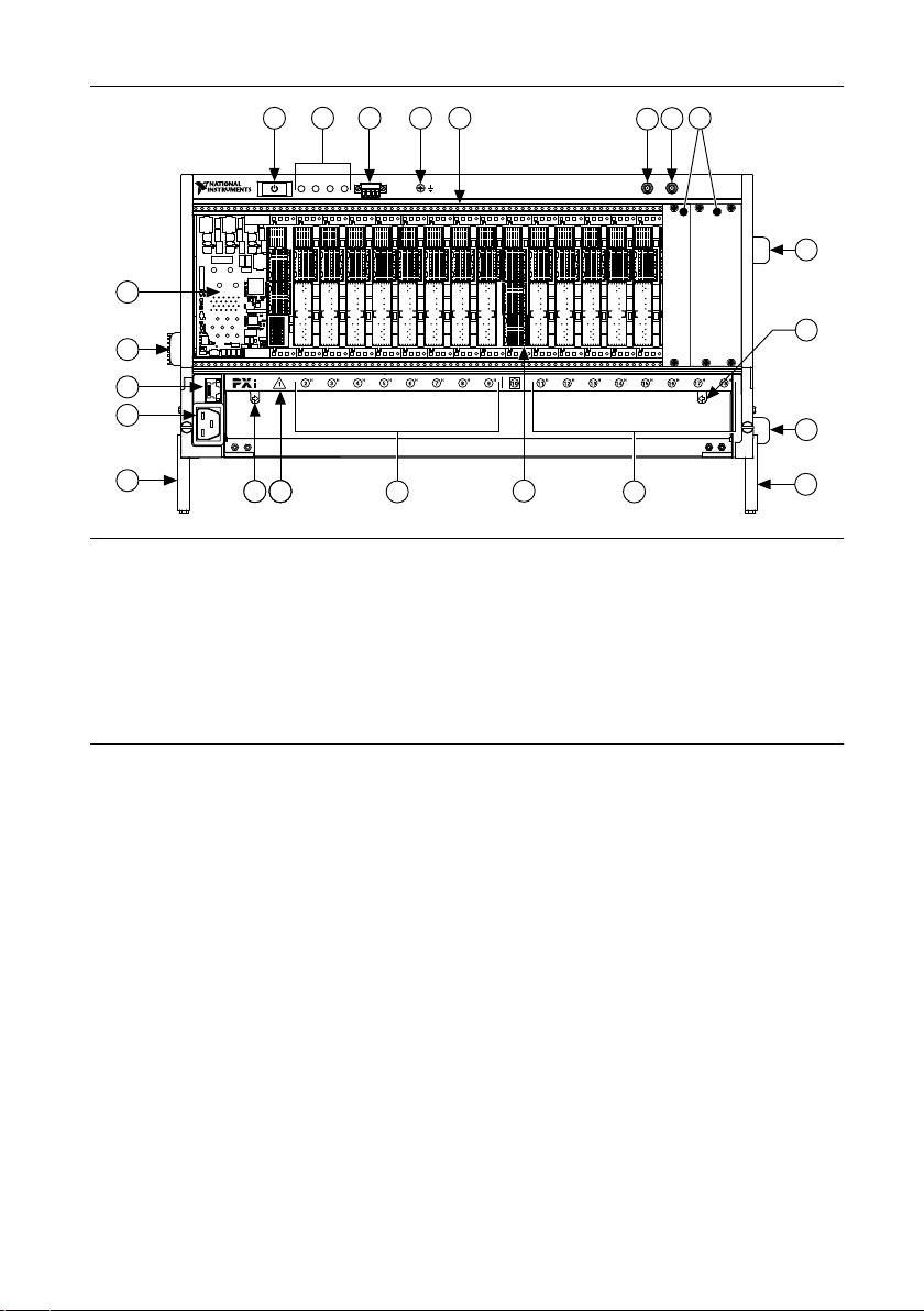
Figure 1. Front View of the PXIe-1086DC
PXIe-1086DC
5
8
4
7
6
3
2
1
9
9
9
10
9
16
17
15
14
814813
11 11
12
810
1. Power Inhibit Switch
2. Status LEDs
3. Inhibit/Fault Connector
4. Ground Terminal
5. Backplane Connectors
6. Clk10 Output
7. Clk10 Input
8. PXI Filler Panels (Optional)
10. Fan Door Latch
11. PXI Express Hybrid Peripheral Slots (16x)
12. PXI Express PXI Express System Timing Slot
13. PXI Express System Controller Slot
14. Chassis Power Connector
15. Ethernet Port
16. Chassis Carry Handle
17. System Controller Expansion Slots
9. Removable Feet
4 | ni.com | PXIe-1086DC User Manual and Specifications
Page 5
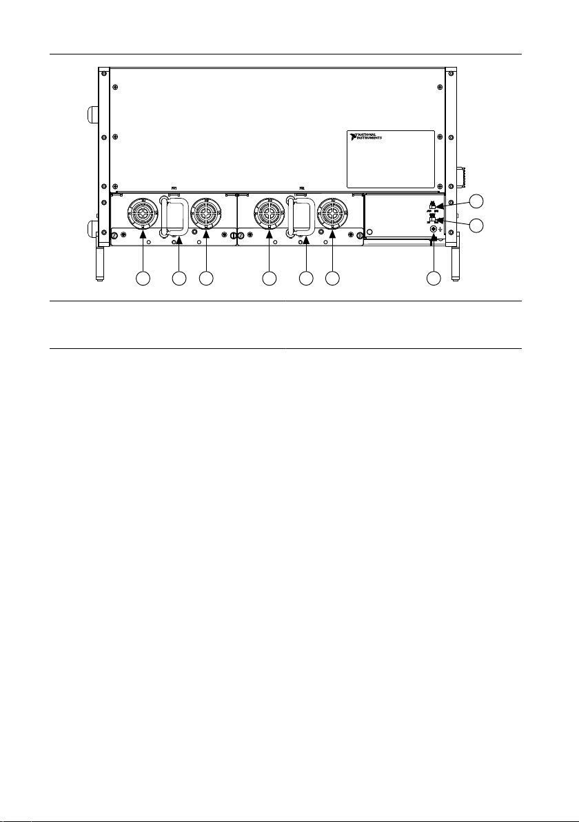
Figure 2. Rear View of the PXIe-1086DC
2
2
1
1
3
1
1
5
4
1. Power Supply Cooling Fan
2. Power Supply Handle
3. Earth Ground Terminal (PE)
4. Inhibit Mode Selector Switch
5. Fan Speed Selector Switch
Optional Equipment
Contact National Instruments to order the following options for the PXIe-1086DC chassis.
EMC Filler Panels
EMC filler panel kits are available from National Instruments.
Power Supply Filler Panels
Optional power supply filler panels are available from National Instruments. Use a power
supply filler panel if you operate the PXIe-1086DC chassis with a single power supply.
Rack Mount Kits
There are two optional kits for mounting the PXIe-1086DC chassis into a rack. The first option
is a pair of mounting brackets for use on the front of the chassis. The second option is a rear
rack mount kit. The rear rack mount kit differs from the front kit to allow for easier installation
into the rack. Refer to NI Chassis Rack Mount Kit Components for more information.
Slot Blockers
PXI Slot Blocker kits are available from National Instruments. Slot Blockers improve cooling
in a chassis by re-routing airflow from empty slots to slots containing PXI modules.
Replacement Power Supply
Replacement power supply kits are available from National Instruments.
PXIe-1086DC User Manual and Specifications | © National Instruments | 5
Page 6

Replacement Fan Modules
Replacement fan modules are available from National Instruments.
PXIe-1086DC Chassis Backplane Overview
Interoperability with CompactPCI
The design of the PXIe-1086DC provides you the flexibility to use the following devices in a
single PXI Express chassis:
• PXI Express compatible products
• CompactPCI Express compatible 2-Link system controller products
• CompactPCI Express compatible Type-2 peripheral products
• PXI peripheral products modified to fit in a hybrid slot
• Standard CompactPCI peripheral products modified to fit in a hybrid slot
System Controller Slot
The system controller slot is Slot 1 of the chassis and is a 2-Link configuration system slot as
defined by the CompactPCI Express and PXI Express specifications. It has three expansion
slots for system controller modules that are wider than one slot. These slots allow the system
controller to expand to the left to prevent it from using peripheral slots.
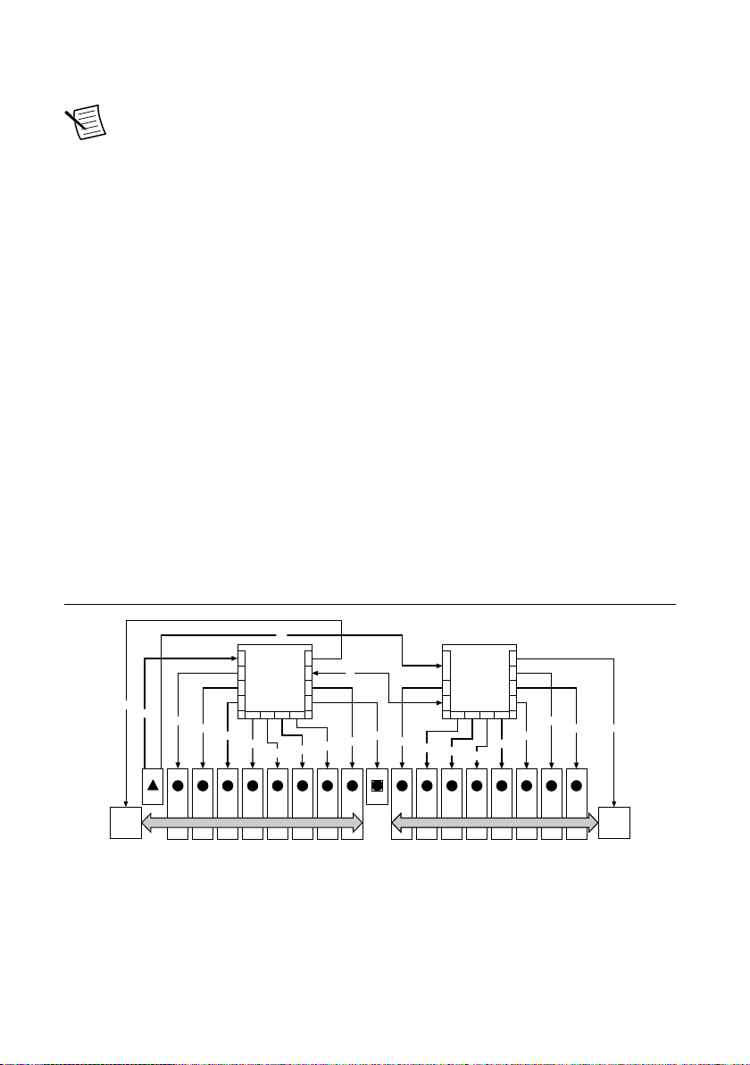
The backplane connects the system slot to two PCI Express switches using a Gen-2 x8 and a
Gen-2 x16 PCI Express link. These switches distribute PCI Express connections to the
peripheral slots and to two PCI Express-to-PCI bridges to provide PCI buses to the hybrid
peripheral slots. Refer to PXIe-1086DC PCI Express Backplane Diagram.
System slot link 1 is a Gen-2 x8 PCI Express link to PCI Express switch 1, providing a
nominal bandwidth of 4 GB/s (single direction) between the system controller and PCI
Express switch 1. PXI Express peripheral slots 2-10 are connected to PCI Express switch 1
with Gen-2 x8 PCI Express links and are downstream of system slot link 1. PCI Express-toPCI bridge 1 is connected to PCI Express switch 1 and provides a 32-bit, 33 MHz PCI bus for
hybrid peripheral slots 2-9. PCI Express switch 1 also is connected to PCI Express switch 2
with a Gen-2 x8 PCI Express link for advanced backplane configurations.
System slot link 2 is a Gen-2 x16 PCI Express link to PCI Express switch 2, providing a
nominal bandwidth of 8 GB/s (single direction) between the system controller slot and PCI
Express switch 2. PXI Express peripheral slots 11-18 are connected to PCI Express switch 2
with Gen-2 x8 PCI Express links and are downstream of system slot link 2. PCI Express-toPCI bridge 2 is connected to PCI Express switch 2 and provides a 32-bit, 33 MHz PCI bus for
hybrid peripheral slots 11-18. PCI Express switch 2 also is connected to PCI Express switch 1
with a Gen-2 x8 PCI Express link for advanced backplane configurations.
The system controller slot also has connectivity to some PXI features such as: PXI_CLK10,
PXI Star, PXI Trigger Bus and PXI Local Bus 6.
6 | ni.com | PXIe-1086DC User Manual and Specifications
Page 7
By default, the system controller will control the power supply with the PS_ON# signal. A
x8
x1
x8
x1
x16
3H2
H
4
H5H6H7H8H9H
11H12H13H14H15H16H17H18
H
PCIe Switch #1
Port 16 Port 17 Port 8 Port 9
PCIe Switch #2
10
1
PCI Bus (32-bit, 33 MHz) to slots 2-9 PCI Bus (32-bit, 33 MHz) to slots 11-18
PCIe-to-
PCI
Bridge #1
Port 0 Port 4 Port 5
Port 17 Port 8 Port 9
Port 12Port 13 Port 20Port 21
Port 16
Port 20
Port 5Port 4Port 1Port 0
Port 21Port 13 Port 12
x8
x8
x8
x8
x8
x8
x8
x8
x8
x8
x8
x8
x8
x8
x8
x8
x8
PCIe-to-
PCI
Bridge #2
logic low on this line will turn the power supply on.
Note The Inhibit Mode switch on the rear of the chassis must be in the Default
position for the system controller to have control of the power supply. Refer to the
Inhibit Mode Switch section for details about the Inhibit Mode switch.
Hybrid Peripheral Slots
The chassis provides 16 hybrid peripheral slots as defined by the PXI-5 PXI Express Hardware
Specification: slots 2 to 9 and slots 11 to 18. A hybrid peripheral slot can accept the following
peripheral modules:
• A PXI Express peripheral with x8, x4, or x1 PCI Express link through a switch to the
system slot. Each PXI Express peripheral slot can link up to a Gen-2 x8 PCI Express,
providing a maximum nominal single-direction bandwidth of 4 GB/s.
• A CompactPCI Express Type-2 Peripheral with x8, x4, or x1 PCI Express link through a
PCI Express switch to the system slot.
• A hybrid-compatible PXI Peripheral module modified by replacing the J2 connector with
an XJ4 connector installed in the upper eight rows of J2. Refer to the PXI Express
Specification for details. The PXI peripheral communicates through the backplane’s 32bit PCI bus.
• A CompactPCI 32-bit peripheral on the backplane’s 32-bit PCI bus.
The hybrid peripheral slots provide full PXI Express functionality and 32-bit PXI functionality
except for PXI Local Bus. The hybrid peripheral slot only connects to PXI Local Bus 6 left
and right.
Figure 3. PXIe-1086DC PCI Express Backplane Diagram
PXIe-1086DC User Manual and Specifications | © National Instruments | 7
Page 8

System Timing Slot
1 2H3H4H5H6H7H8H9H10 11H12H13H14H15H16H17H18
H
DSTAR 6
DSTAR 5
DSTAR 7
DSTAR 4
DSTAR 3
DSTAR 2
DSTAR 1
DSTAR 15
DSTAR 14
DSTAR 13
DSTAR 16
DSTAR 12
DSTAR 11
DSTAR 10
STAR 7
STAR 8
STAR 6
STAR 5
STAR 4
STAR 3
STAR 2
STAR 1 STAR 10
STAR 11
STAR 12
STAR 13
STAR 14
STAR 15
STAR 16
DSTAR 8
DSTAR 9
DSTAR 0
STAR 9
STAR 0
The system timing slot is slot 10. The system timing slot accepts the following peripheral
modules:
• A PXI Express System Timing Module with x8, x4, or x1 PCI Express link to the system
slot through a PCI Express switch. Each PXI Express peripheral slot can link up to a
Gen-2 x8 PCI Express, providing a maximum nominal single-direction bandwidth of 4
GB/s.
• A PXI Express Peripheral with x8, x4, or x1 PCI Express link to the system slot through a
PCI Express switch.
• A CompactPCI Express Type-2 Peripheral with x8, x4, or x1 PCI Express link to the
system slot through a PCI Express switch.
The system timing slot has three (3) dedicated differential pairs (PXIe_DSTAR) connected
from the TP1 and TP2 connectors to the XP3 connector for each PXI Express hybrid
peripheral slot, as well as routed back to the XP3 connector of the system timing slot, as
shown in the following figure. You can use the PXIe_DSTAR pairs for high-speed triggering,
synchronization, and clocking. Refer to the PXI Express Specification for details.
The system timing slot also has a single-ended (PXI Star) trigger connected to every slot.
Refer to the following figure for more details.
The system timing slot has a pin (PXI_CLK10_IN) through which a system timing module
may source a 10 MHz clock to which the backplane phase-locks. Refer to the System
Reference Clock section for details.
The system timing slot has a pin (PXIe_SYNC_CTRL) through which a system timing module
can control the PXIe_SYNC100 timing. Refer to the PXI Express Specification and the PXIe
SYNC CTRL section of this chapter for details.
Figure 4. PXIe_DSTAR and PXI Star Connectivity Diagram
8 | ni.com | PXIe-1086DC User Manual and Specifications
Page 9
PXI Local Bus
7H8H9
H
10
11H12
H
PXI Trigger Bus #2
PXI
Trigger
Bridge #2
PXI
Trigger
Bridge #1
1
2H3H4H5H6
H
PXI Trigger Bus #1
13H14H15H16H17H18
H
PXI Trigger Bus #3
The PXI backplane local bus is a daisy-chained bus that connects each peripheral slot with
adjacent peripheral slots to the left and right.
The backplane routes PXI Local Bus 6 between all slots. The left local bus 6 from slot 1 is not
routed anywhere, and the right local bus 6 from slot 18 is not routed anywhere.
Local bus signals may range from high-speed TTL signals to analog signals as high as 42 V.
Initialization software uses the configuration information specific to each adjacent peripheral
module to evaluate local bus compatibility.
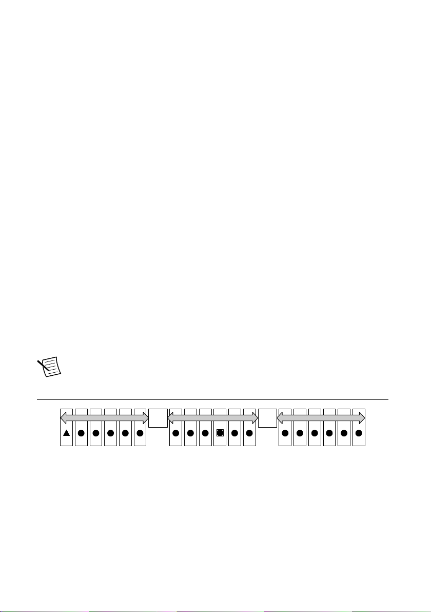
PXI Trigger Bus
All slots on the same PXI bus segment share eight PXI trigger lines. You can use these trigger
lines in a variety of ways. For example, you can use triggers to synchronize the operation of
several different PXI peripheral modules. In other applications, one module located in the
system timing slot can control carefully timed sequences of operations performed on other
modules in the system. Modules can pass triggers to one another on the lines, allowing
precisely timed responses to asynchronous external events the system is monitoring or
controlling.
The PXI trigger lines from adjacent PXI trigger bus segments can be routed in either direction
across the PXI trigger bridges through buffers. This allows you to send trigger signals to, and
receive trigger signals from, every slot in the chassis. Static trigger routing (user-specified line
and directional assignments) can be configured through Measurement & Automation Explorer
(MAX). Dynamic routing of triggers (automatic line assignments) is supported through certain
National Instruments drivers like NI-DAQmx.
System Reference Clock
The PXIe-1086DC chassis supplies PXI_CLK10, PXIe_CLK100 and PXIe_SYNC100 to
every peripheral slot with an independent driver for each signal.
An independent buffer (having a source impedance matched to the backplane and a skew of
less than 1 ns between slots) drives PXI_CLK10 to each peripheral slot. You can use this
common reference clock signal to synchronize multiple modules in a measurement or control
system.
Note Although any trigger line may be routed in either direction, it cannot be
routed in more than one direction at a time.
Figure 5. PXI Trigger Bus Connectivity Diagram
PXIe-1086DC User Manual and Specifications | © National Instruments | 9
Page 10
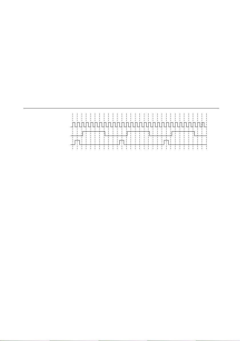
An independent buffer drives PXIe_CLK100 to each peripheral slot. These clocks are matched
PXIe_CLK100
PXI_CLK10
PXIe_SYNC100
0 1 2 3 4 5 6 7 8 9 0 1 2 3 4 5 6 7 8 9 0 1 2 3 4 5 6 7 8 9
in skew to less than 100 ps. The differential pair must be terminated on the peripheral with
LVPECL termination for the buffer to drive PXIe_CLK100 so that when there is no peripheral
or a peripheral that does not connect to PXIe_CLK100, there is no clock being driven on the
pair to that slot.
An independent buffer drives PXIe_SYNC100 to each peripheral slot. The differential pair
must be terminated on the peripheral with LVPECL termination for the buffer to drive
PXIe_SYNC100 so that when there is no peripheral or a peripheral that does not connect to
PXIe_SYNC100, there is no SYNC100 signal being driven on the pair to that slot.
PXI_CLK10, PXIe_CLK100 and PXIe_SYNC100 have the default timing relationship
described in the following figure.
Figure 6. System Reference Clock Default Behavior
To synchronize the system to an external clock, you can drive PXI_CLK10 from an external
source through the PXI_CLK10_IN pin on the System Timing Slot. Refer to the System
Timing Slot XP4 Connector Pinout section for the pinout. When a 10MHz clock is detected on
this pin, the backplane automatically phase-locks the PXI_CLK10, PXIe_CLK100, and
PXIe_SYNC100 signals to this external clock and distributes these signals to the slots. Refer
to the Specifications for the specification information for an external clock provided on the
PXI_CLK10_IN pin of the system timing slot.
You also can drive a 10 MHz clock on the 10 MHz REF IN connector on the front of the
chassis. When a 10 MHz clock is detected on this connector, the backplane automatically
phase-locks the PXI_CLK10, PXIe_CLK100, and PXIe_SYNC100 signals to this external
clock and distributes these signals to the slots. Refer to the Specifications section for the
specification information for an external clock provided on the 10 MHz REF IN connector on
the front panel of the chassis.
If the 10 MHz clock is present on both the PXI_CLK10_IN pin of the System Timing Slot and
the 10 MHz REF IN connector on the front of the chassis, the signal on the System Timing
Slot is selected. Refer to the following table which explains how the 10 MHz clocks are
selected by the backplane.
10 | ni.com | PXIe-1086DC User Manual and Specifications
Page 11

Table 1. Backplane External Clock Input Configuration
System Timing Slot
PXI_CLK10_IN
Front Chassis
Panel 10 MHz REF
IN
Backplane PXI_CLK10, PXIe_CLK100
and PXIe_SYNC100
No clock present No clock present Backplane generates its own clocks
No clock present 10 MHz clock
present
PXI_CLK10, PXIe_CLK100 and
PXIe_SYNC100 all phase-locked to front
Chassis Panel—10 MHz REF IN
10 MHz clock present No clock present PXI_CLK10, PXIe_CLK100 and
PXIe_SYNC100 all phase-locked to
System Timing Slot— PXI_CLK10_IN
10 MHz clock present 10 MHz clock
present
PXI_CLK10, PXIe_CLK100 and
PXIe_SYNC100 all phase-locked to
System Timing Slot— PXI_CLK10__IN
A copy of the backplane’s PXI_CLK10 is exported to the 10 MHz REF OUT connector on the
front of the chassis. This clock is driven by an independent buffer.
PXIe_SYNC_CTRL
PXIe_SYNC100 is by default a 10 ns pulse synchronous to PXI_CLK10. The frequency of
PXIe_SYNC100 is 10/n MHz, where n is a positive integer. The default for n is 1, giving
PXIe_SYNC100 a 100 ns period. However, the backplane allows n to be programmed to other
integers. For example, setting n = 3 gives a PXIe_SYNC100 with a 300 ns period while still
maintaining its phase relationship to PXI_CLK10. The value for n can be any positive integer
from 1 to 255.
The system timing slot has a control pin for PXIe_SYNC100 called PXIe_SYNC_CTRL for
use when n > 1. Refer to System Timing Slot XP3 Connector Pinout for the pinout. Refer to the
Specifications for the PXIe_SYNC_CTRL input specifications.
By default, a high-level detected by the backplane on the PXIe_SYNC_CTRL pin causes a
synchronous restart for the PXIe_SYNC100 signal. On the next PXI_CLK10 edge the
PXIe_SYNC100 signal restarts. This allows several chassis to have their PXIe_SYNC100 in
phase with each other. Refer to the following figure for timing details with this method.
PXIe-1086DC User Manual and Specifications | © National Instruments | 11
Page 12
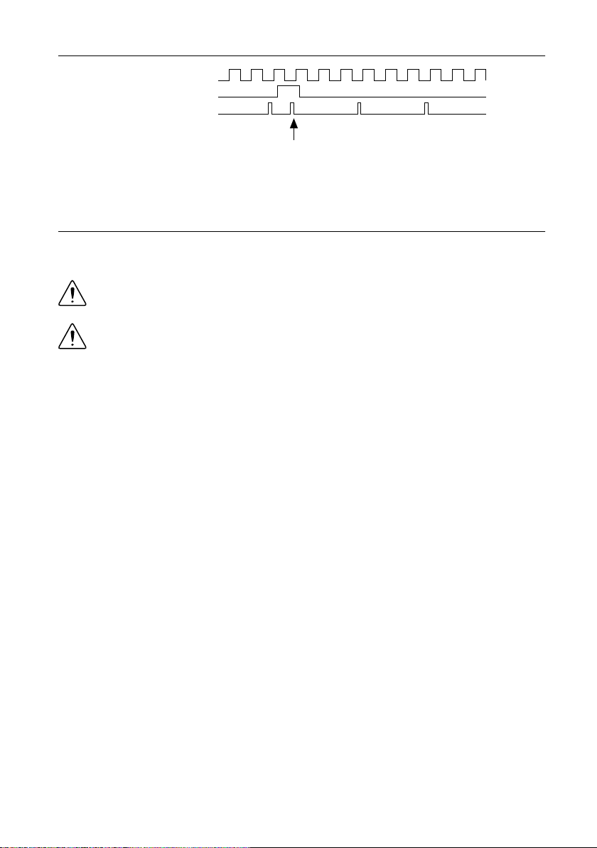
Figure 7. PXIe_SYNC100 at 3.33 MHz Using PXIe_SYNC_CTRL as Restart
PXI_CLK10
PXIe_SYNC_CTRL
PXIe_SYNC100
SYNC100 Divider
Restarted Here
Installation and Configuration
Safety Information
Caution Before undertaking any troubleshooting, maintenance, or exploratory
procedure, carefully read the following caution notices.
Caution Protection may be impaired if equipment is not used in the manner
specified.
This equipment contains voltage hazardous to human life and safety, and is capable of
inflicting personal injury.
• Chassis Grounding—The chassis requires a connection from the premise wire safety
ground to the chassis ground. The earth safety ground must be connected during use of
this equipment to minimize shock hazards. Refer to the Connecting Safety Ground section
for instructions on connecting safety ground.
• Live Circuits—Operating personnel and service personnel must not remove protective
covers when operating or servicing the chassis. Adjustments and service to internal
components must be undertaken by qualified service technicians. During service of this
product, the mains connector to the premise wiring must be disconnected. Dangerous
voltages may be present under certain conditions; use extreme caution.
• Explosive Atmosphere—Do not operate the chassis in conditions where flammable gases
are present. Under such conditions, this equipment is unsafe and may ignite the gases or
gas fumes.
• Part Replacement—Only service this equipment with parts that are exact replacements,
both electrically and mechanically. Contact National Instruments for replacement part
information. Installation of parts with those that are not direct replacements may cause
harm to personnel operating the chassis. Furthermore, damage or fire may occur if
replacement parts are unsuitable.
12 | ni.com | PXIe-1086DC User Manual and Specifications
Page 13

• Modification—Do not modify any part of the chassis from its original condition.
Unsuitable modifications may result in safety hazards.
• Location—The chassis is for use in stationary (non-moveable), restricted access locations
such as a desk or bench, or for installation in a rack only. Installation and maintenance are
to be performed by skilled/trained service persons.
Chassis Cooling Considerations
The PXIe-1086DC chassis is designed to operate on a bench or in an instrument rack. The
chassis must be oriented horizontally with the primary exhaust vent at top. Vertical orientation
with the chassis handle up is not a supported configuration. Regardless of the configuration,
you must provide the cooling clearances as outlined in the following sections.
Providing Adequate Clearance
The primary cooling exhaust vent for the PXIe-1086DC is on the top of the chassis. The
primary intake vent is on the bottom of the chassis. The secondary intake vents are located
along on the rear of the chassis. Adequate clearance between the chassis and surrounding
equipment or blockages must be maintained to ensure proper cooling of the chassis power
supply as well as the modules plugged into the chassis. These clearances are outlined in the
following figures. Failure to provide these clearances may result in thermal-related failures in
the chassis or modules.
PXIe-1086DC User Manual and Specifications | © National Instruments | 13
Page 14
1.75
(44.5)
3.00
(76.2)
Dimensions are in inches (millimeters)
1.75
(44.5)
PXIe-1086DC
H
Figure 8. PXIe-1086DC Cooling Clearances
The vent locations are shown in the following figure.
14 | ni.com | PXIe-1086DC User Manual and Specifications
Page 15
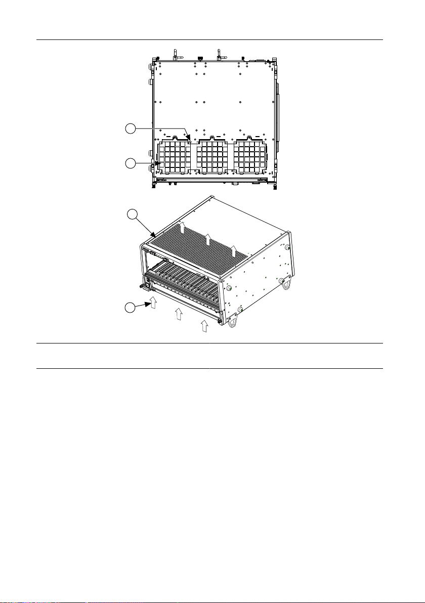
Figure 9. PXIe-1086DC Vents
PXIe-1086DC
4
2
1
3
1. Ambient Temperature Sensor
2. PXI Module Air Intake (3x)
3. PXI Module Air Exhaust Vent
4. Airflow
Chassis Ambient Temperature Definition
The chassis fan control system uses ambient intake air temperatures for controlling fan speeds
when in Auto Fan Speed mode. Because of this, the chassis ambient temperature is defined as
the temperature of the air just outside of the fan intake vents on the bottom of the chassis. Note
that this temperature may be higher than ambient room temperature depending on the
surrounding equipment and/or blockages present. Ensure ambient intake temperatures do not
exceed the ratings in the Operating Environment section of the PXIe-1086DC Specifications.
If the temperature exceeds the stated spec, the front-panel temperature LED blinks red.
Setting Fan Speed
The fan-speed selector switch is on the chassis rear panel. Refer to Rear View of the
PXIe-1086DC to locate the fan-speed selector switch. Select High for maximum cooling
performance or Auto for improved acoustic performance. When set to Auto, the chassis intake
air temperature determines the fan speed.
PXIe-1086DC User Manual and Specifications | © National Instruments | 15
Page 16
Installing Filler Panels
Dimensions are in inches (millimeters)
0.35
(8.9)
To maintain proper module cooling performance, install filler panels (provided with the
chassis) in unused or empty slots. Secure with the captive mounting screws provided.
Installing Slot Blockers
The cooling performance of the chassis can be improved by installing optional slot blockers.
Refer to the National Instruments website at ni.com/info and enter the Info Code
slotblocker for more information about slot blockers.
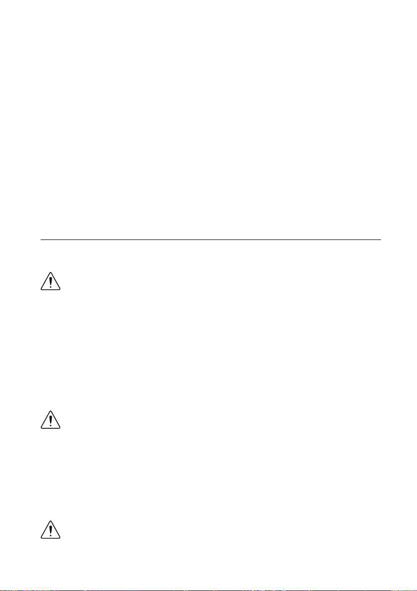
Fan Access Door Clearance
When installing the PXIe-1086DC chassis, you also must provide the proper clearance for the
fan access door to open fully, as shown in the following figure.
Figure 10. Fan Access Door Clearance
Rack Mounting
Rack mount applications require optional rack mount kits available from National Instruments.
Refer to the instructions supplied with the rack mount kits to install your PXIe-1086DC
chassis in an instrument rack. Refer to NI Chassis Rack Mount Kit Components for more
information.
Note You may want to remove the feet from the PXIe-1086DC chassis when rack
mounting. To do so, remove the screw holding the feet and handle in place.
Connecting to Safety Ground and Power Source
The PXIe-1086DC chassis has a single power connector that supplies input power to both
chassis power supplies. The power connector is on the front panel.
16 | ni.com | PXIe-1086DC User Manual and Specifications
Page 17

The PXIe-1086DC ships with a power cord that has an appliance coupler and leads for
3
2
1
connection to the source. The cord requires custom termination. The following figure shows
the cord connector pinout.
You can order an additional or replacement cord from National Instruments. Part number
782108-01 is a US/CAN approved 3 m, three-conductor, 18 AWG cord with leads and suitable
for use in North America. Part number 785863-01 is an international harmonized power cord,
3 m, three-conductor, 1.0mm2 cord with leads and suitable for use in the EU and
internationally. Installation must be done in accordance with local electric codes.
Caution The PXIe-1086DC chassis must have a safety ground (protective earth),
which is connected by the installer to the premise safety ground system for safe
operation. The supplied power cord has a green ground wire for this purpose. The
safety ground method shall be reliable and meet applicable safety codes.
Attention Pour un fonctionnement en toute sécurité, le châssis PXIe-1086DC doit
disposer d'un fil de protection (mise à la terre) relié par l'installateur au système de
mise à la terre du site. Le cordon d'alimentation fourni dispose d'un fil de protection
vert prévu à cet effet. La méthode de mise à la terre doit être fiable et respecter les
codes de sécurité applicables.
The Earth Ground Terminal on the rear of the chassis must be used where the power cord is
terminated via a standard power plug (for example, IEC 60320, NEMA 5-15). This provides a
supplemental protective earthing connection to prevent shock hazards if the ground in the plug
were to be interrupted. Complete the following steps to connect a protective conductor to this
terminal:
1. Connect a 18 AWG wire to the Earth Ground Terminal using a grounding lug. The wire
must have green insulation with a yellow stripe or must be noninsulated (bare). The lug
must be sized for the M4 x 6 screw.
2. Attach the opposite end of the wire to permanent earth ground using toothed washers or a
toothed lug.
1. Protective Earth (Ground)
2. Power (-, Neutral)
3. Power (+, Hot)
Figure 11. Power Connector
PXIe-1086DC User Manual and Specifications | © National Instruments | 17
Page 18

Notice
To ensure the specified EMC performance with a second chassis power supply,
install a snap-on ferrite bead (NI part number 711849-01) onto the power cord as
close to the input connector as possible. You can order this ferrite bead directly from
NI using the Order By Part Number link on the home page at ni.com. Order the
following part number: 781233-02 EMI suppression ferrite, 10.2 mm (includes NI
part number 711849-01 (Fair-Rite 0443167251, type 43, round cable, 10.2 mm/
0.402 in. ID, 225 Ω @ 100 MHz)).
Power-On Test
Caution Do not install modules prior to performing the following power-on test.
Caution To completely remove power, you must disconnect all power cables.
The PXIe-1086DC chassis has two slots for inserting power supplies on the rear of the chassis.
A power supply must be installed in one or both of these slots to power on the chassis.
Use the Inhibit Mode switch to power on the chassis or place it in standby mode. Set the
Inhibit Mode switch on the back of the chassis to the Manual position. Observe that all fans
become operational and that all chassis LEDs are steady green. Set the Inhibit Mode switch
back to the Default position to allow the system controller to control the power supply.
Installing a PXI Express System Controller
This section contains general installation instructions for installing a PXI Express system
controller in a PXIe-1086DC chassis. Refer to your PXI Express system controller user
manual for specific instructions and warnings. To install a system controller, complete the
following steps:
1. Ensure that the chassis is properly grounded to protect it from electrical damage while
you install the system controller.
2. Install the system controller into the system controller slot (slot 1, indicated by the red
card guides) by first placing the system controller PCB into the front of the card guides
(top and bottom). Slide the system controller to the rear of the chassis, making sure that
the injector/ejector handle is pushed down as shown in the following figure.
18 | ni.com | PXIe-1086DC User Manual and Specifications
Page 19

Figure 12. Installing a PXI Express System Controller
NI PXIe-1086
4
3
2
1
1. Controller Front Panel Mounting Screws (4x)
2. NI PXI Express System Controller
3. Injector/Ejector Handle
4. PXIe-1086DC Chassis
3. When you begin to feel resistance, pull up on the injector/ejector handle to seat the
system controller fully into the chassis frame. Secure the system controller front panel to
the chassis using the system controller front panel mounting screws.
4. Connect the keyboard, mouse, and monitor to the appropriate connectors. Connect
devices to ports as required by your system configuration.
5. Power on the chassis. Verify that the system controller boots. If the system controller does
not boot, refer to your system controller user manual.
The following figure shows a PXI Express system controller installed in the system controller
slot of a PXIe-1086DC chassis. You can place CompactPCI, CompactPCI Express, PXI, or
PXI Express modules in other slots depending on the slot type.
PXIe-1086DC User Manual and Specifications | © National Instruments | 19
Page 20

Figure 13. PXI Express System Controller Installed in an PXIe-1086DC Chassis
NI PXIe-1086
1
2
3
1. PXIe-1086DC chassis
2. PXI Express System Controller
3. Injector/Ejector Rail
Installing Peripheral Modules
Caution The PXIe-1086DC chassis has been designed to accept a variety of
peripheral module types in different slots. To prevent damage to the chassis, ensure
that the peripheral module is being installed into a slot designed to accept it. Refer to
the Getting Started section for a description of the various slot types.
This section contains general installation instructions for installing a peripheral module in a
PXIe-1086DC chassis. Refer to your peripheral module user manual for specific instructions
and warnings. To install a module, complete the following steps:
1. Ensure that the chassis is properly grounded to protect it from electrical damage while
you install the module.
2. Ensure that the chassis is powered off.
3. Install a module into a chassis slot by first placing the module card PCB into the front of
the card guides (top and bottom), as shown in the following figure. Slide the module to
the rear of the chassis, making sure that the injector/ejector handle is pushed down as
shown in the following figure.
4. When you begin to feel resistance, push up on the injector/ejector handle to fully seat the
module into the chassis frame. Secure the module front panel to the chassis using the
module front-panel mounting screws.
20 | ni.com | PXIe-1086DC User Manual and Specifications
Page 21

Figure 14. Installing PXI, PXI Express, or CompactPCI Peripheral Modules
NI PXIe-1086
5
4
6
3
2
1
1. Injector/Ejector Handle
2. PXI Peripheral Module
3. Peripheral Module Front Panel Mounting Screws
(2x)
4. PXI Express System Controller
5. PXIe-1086DC Chassis
6. Injector/Ejector Rail
Remote System Monitoring
The PXIe-1086DC chassis provides an Ethernet port on the front panel of the chassis. You can
use this Ethernet port to monitor the chassis operating parameters remotely over a network.
The Ethernet port on the chassis supports communication speeds of 10 Mbps and 100 Mbps.
Contact your network administrator to determine whether your network supports DHCP. If
your network uses DHCP, the network configuration is performed automatically. Refer to
Front View of the PXIe-1086DC to locate the Ethernet port
To use the remote monitoring interface, connect one end of an Ethernet cable to your
PXIe-1086DC chassis. Connect the other end of the cable to your Ethernet network.
Note The Ethernet controller can perform automatic crossover, thus eliminating the
need for crossover cables.
Through the remote monitoring Ethernet interface of the chassis, you can access a web page
with information about the current chassis operating parameters. You can access this page in
most browsers. Enter the IP address or hostname currently assigned to the chassis into the
browser’s address bar.
PXIe-1086DC User Manual and Specifications | © National Instruments | 21
Page 22

Figure 15. Chassis Configuration Web Page
The Ethernet connector has two LEDs that indicate the current status of the Ethernet link.
Table 2. Ethernet LED Behavior
LED State Description
Off Link is not established.
ACT/Link
10/100
Steady green Link is established.
Blinking green Chassis is communicating with another device on the network.
Off 10 Mbps data rate is selected.
Steady green 100 Mbps data rate is selected.
Default Configuration Settings
The chassis ships from the factory with the following default configuration settings:
• DHCP with Auto IP fallback
• Default hostname as printed on the product label
LED Indicators
The PXIe-1086DC chassis has four main LEDs on the front panel next to the Power Inhibit
switch. Refer to Front View of the PXIe-1086DC to locate these LEDs. You can use the four
main LEDs to determine the chassis operating status quickly.
22 | ni.com | PXIe-1086DC User Manual and Specifications
Page 23

Table 3. Main Chassis LED Behavior
LED State Description
Off Chassis is powered off.
Temperature Status
Fan Status
Power Supply 1 Status
Steady green
Blinking red
Steady red
Air intake temperature is within chassis operating
range.
Air intake temperature is outside of chassis operating
range.
Air intake or exhaust temperature has reached critical
limits.
Off Chassis is powered off.
Steady green All chassis fans are enabled and operating normally.
Blinking red
Steady red
One or more chassis fans have failed, but chassis can
continue to operate.
One or more chassis fans have failed, and chassis
must shut itself down.
Off Power supply is not installed or is in standby.
Steady green
Blinking red
Power supply is active, and all voltages are within
normal operating ranges.
Power supply is active, and at least one voltage is out
of range.
Steady red Power supply has failed.
Off Power supply is not installed or is in standby.
Steady green
Power supply is active, and all voltages are within
normal operating ranges.
Power Supply 2 Status
Blinking red
Power supply is active, and at least one voltage is out
of range.
Steady red Power supply has failed.
Each chassis fan assembly has an LED that shows the current health of that fan.
PXIe-1086DC User Manual and Specifications | © National Instruments | 23
Page 24

Table 4. Chassis Fan LED Behavior
LED State Description
Off Fan is not enabled.
Individual Fan Status
Each power supply also has an LED that shows the power supply’s current health.
LED State Description
Individual Power Supply Status
Steady green Fan is operating normally.
Steady red Fan has failed.
Table 5. Power Supply LED Behavior
Off Power supply is in standby.
Steady green Power supply is operating normally.
Steady red Power supply has failed.
Remote Inhibit and Fault Monitoring
The PXIe-1086DC chassis supports remote inhibit and fault monitoring through a 4-pin
terminal block on the chassis front panel. Refer to Front View of the PXIe-1086DC to locate
this connector.
Table 6. Remote Inhibit and Fault Connector Pinout
Pin Signal
1 Remote Inhibit (active low)
2 Ground
3 Remove Fault (active high)
4 Ground
When the chassis Inhibit Mode switch is in the Manual position, you can use the Remote
Inhibit signal to control the chassis power supplies. Refer to the Inhibit Mode Switch section
for details.
The Remote Fault signal is an output signal that is asserted high when any chassis fault is
detected. You can use this signal to monitor the overall chassis health.
Inhibit Mode Switch
On the rear panel of the chassis there is an Inhibit Mode switch. Refer to Rear View of the
PXIe-1086DC to locate this switch.
24 | ni.com | PXIe-1086DC User Manual and Specifications
Page 25

The Inhibit Mode switch should be in the Default position when normal power inhibit switch
functionality is desired. If the user needs to power on a chassis without a system controller
installed the switch should be in the Manual position.
When the Inhibit Mode switch is set to the Manual position, the power supplies are enabled,
and you can use the Inhibit signal (active low) on pin 1 of the Remote Inhibit and Fault
connector to power off the chassis. To power off the chassis remotely, connect the Inhibit pin
(pin 1) to a Logic Ground pin (pin 2). As long as this connection exists, the chassis will remain
off (standby); when you remove this connection, the chassis turns on.
Note For the Remote Inhibit signal to control the On/Off (standby) state of the
chassis, the Inhibit Mode switch must be in the Manual position.
PXI_CLK10 Front Panel Connectors
There are two SMA connectors on the front of the PXIe-1086DC chassis for PXI_CLK10. The
connectors are labeled IN and OUT. You can use them for supplying the backplane with
PXI_CLK10 or routing the backplane’s PXI_CLK10 to another chassis. Refer to the System
Reference Clock section for details about these signals.
PXI Express System Configuration with MAX
The PXI Platform Services software included with your chassis automatically identifies your
PXI Express system components to generate a pxiesys.ini file. You can configure your
entire PXI system and identify your chassis through Measurement & Automation Explorer
(MAX), included with your system controller. PXI Platform Services creates the
pxiesys.ini and pxisys.ini file, which define your PXI system parameters.
MAX provides the following chassis information:
• Asset information, such as serial number or part number
• Chassis number
• Voltages, temperatures, and fan speeds
• Ethernet monitoring port configuration
• Slot details
• Chassis self-test
• Firmware Update
PXIe-1086DC User Manual and Specifications | © National Instruments | 25
Page 26

Figure 16. MAX Interface
Trigger Configuration in MAX
PXI Platform Services provides an interface to route and reserve triggers so dynamic routing,
through drivers such as NI-DAQmx, avoids double-driving and potentially damaging trigger
lines. For more information about routing and reserving PXI triggers, refer to Info Code
wf17sp at ni.com/support.
Each chassis has one or more trigger buses, each with eight lines numbered 0 through 7 that
can be reserved and routed statically or dynamically. Static reservation pre-allocates a trigger
line to prevent its configuration by a user program. Dynamic reservation/routing/deallocation
is on the fly within a user program based on National Instruments APIs such as NI-DAQmx.
NI recommends dynamic reservations and routing are used whenever possible. If static
reservations are required, static reservation of trigger lines can be implemented by the user in
MAX through the Triggers tab. PXI modules dynamically configured by programs such as
NI-DAQmx will not use reserved trigger lines. This prevents the instruments from doubledriving the trigger lines, possibly damaging devices in the chassis. In the default configuration,
trigger lines on each bus are independent. For example, if trigger line 3 is asserted on trigger
bus 0, by default it is not asserted automatically on any other trigger bus.
Complete the following steps to reserve these trigger lines in MAX.
1. In the Configuration tree, click the PXI chassis branch to configure.
2. In the lower right pane, click the Triggers tab.
3. Select the trigger lines to statically reserve.
4. Click the Save button.
26 | ni.com | PXIe-1086DC User Manual and Specifications
Page 27

PXI Trigger Bus Routing
Some National Instruments chassis, such as the PXIe-1086DC, have the capability to route
triggers from one bus to others within the same chassis using the Trigger Routing tab in
MAX.
Note Selecting any non-disabled routing automatically reserves the line in all
trigger buses being routed to. If you are using NI-DAQmx, it will reserve and route
trigger lines for you, so you won’t have to route trigger lines manually.
Complete the following steps to configure trigger routings in MAX.
1. In the Configuration tree, select the chassis in which you want to route trigger lines.
2. In the right-hand pane, select the Triggers tab near the bottom.
3. For each trigger line, select Route Right, Route Outward From Middle, or Route Left to
route triggers on that line in the described direction, or select Disabled for the default
behavior with no manual routing.
4. Click the Save button.
Figure 17. Trigger Configuration
Using System Configuration and Initialization Files
The PXI Express specification allows many combinations of PXI Express chassis and system
modules. To assist system integrators, the manufacturers of PXI Express chassis and system
modules must document the capabilities of their products. The minimum documentation
requirements are contained in .ini files, which consist of ASCII text. System integrators,
configuration utilities, and device drivers can use these .ini files.
PXIe-1086DC User Manual and Specifications | © National Instruments | 27
Page 28
The capability documentation for the PXIe-1086DC chassis is contained in the chassis.ini
file on the software media that comes with the chassis. The information in this file is combined
with information about the system controller to create a single system initialization file called
pxisys.ini (PXI System Initialization). The system controller manufacturer either provides
a pxisys.ini file for the particular chassis model that contains the system controller or
provides a utility that can read an arbitrary chassis.ini file and generate the corresponding
pxisys.ini file. System controllers from NI provide the pxisys.ini file for the
PXIe-1086DC chassis, so you should not need to use the chassis.ini file. Refer to the
documentation provided with the system controller or to ni.com/support for more
information on pxisys.ini and chassis.ini files.
Device drivers and other utility software read the pxisys.ini file to obtain system
information. The device drivers should have no need to directly read the chassis.ini file.
For detailed information regarding initialization files, refer to the PXI Express specification at
www.pxisa.org.
Maintenance
This section describes basic maintenance procedures you can perform on the PXIe-1086DC
chassis.
Caution Disconnect the power cable prior to servicing your
PXIe-1086DC chassis.
Service Interval
Clean dust from the chassis exterior (and interior) as needed, based on the operating
environment. Periodic cleaning increases reliability
.
Preparation
The information in this section is designed for use by qualified service personnel. Read the
PXIe-1086DC Safety, Environmental, and Regulatory Information document included with
your kit before attempting any procedures in this section.
Caution Many components within the chassis are susceptible to static dischar
damage. Service the chassis only in a static-free environment. Observe standard
handling precautions for static-sensitive devices while servicing the chassis. Always
wear a grounded wrist strap or equivalent while servicing the chassis.
ge
Cleaning
Cleaning procedures consist of exterior and interior cleaning of the chassis. Refer to your
module's user documentation for information about cleaning individual CompactPCI or PXI
Express modules.
Caution Always disconnect the power cable prior to servicing the chassis.
28 | ni.com | PXIe-1086DC User Manual and Specifications
Page 29

Interior Cleaning
Use a dry, low-velocity stream of air to clean the interior of the chassis. Use a soft-bristle
brush for cleaning around components.
Exterior Cleaning
Clean the exterior surfaces of the chassis with a dry, lint-free cloth or a soft-bristle brush. If
any dirt remains, wipe with a cloth moistened in a mild soap solution. Remove any soap
residue by wiping with a cloth moistened with clear water. Do not use abrasive compounds on
any part of the chassis.
Caution Avoid getting moisture inside the chassis during exterior cleaning,
especially through the top vents. Use just enough moisture to dampen the cloth.
Do not wash the front- or rear-panel connectors or switches. Cover these
components while cleaning the chassis.
Do not use harsh chemical cleaning agents; they may damage the chassis. Avoid
chemicals that contain benzene, toluene, xylene, acetone, or similar solvents.
Replacing a Modular Power Supply
This section describes how to remove and install a modular power supply for the
PXIe-1086DC chassis.
Caution Disconnect the power cable prior to replacing the power supply.
Attention Débranchez le câble d'alimentation avant de remplacer le bloc
d'alimentation.
Caution Do not use a power supply from another chassis. Doing so may damage
your chassis and the power supply. You must ensure the chassis is properly grounded
after any maintenance.
Attention N'essayez pas d'utiliser un bloc d'alimentation provenant d'un modèle de
châssis différent du vôtre. Cela pourrait endommager votre châssis et le bloc
d'alimentation.
Refer to Connecting to Safety Ground and Power Source for instructions on connecting safety
ground.
Removal of Power Supply
The PXIe-1086DC power supply (part number 782106-01) is a replacement part for the
PXIe-1086DC chassis. Before attempting to replace a power supply, verify that there is
adequate clearance behind the chassis.
The power supplies for this chassis are redundant and hot swappable. If both power supplies
are installed and functional, you can remove either without disconnecting main AC power
PXIe-1086DC User Manual and Specifications | © National Instruments | 29
Page 30

from the system. If both power supplies are installed, and one has failed, you can remove the
1
2
3
2
failed supply without disconnecting main AC power from the system.
Complete the following steps to remove a power supply from the rear of the chassis:
Caution Before handling the power supply, allow the fan to stop spinning.
1. Disengage the two screws on the rear of the power supply with a flat-blade screwdriver.
2. Extend the collapsible handle and pull the power supply out of the chassis.
Figure 18. Removing Power Supply from the PXIe-1086DC Chassis
1. Power Supply
2. Captive Screw
3. Collapsible Handle
Removal of Power Drawer
If access to the rear of the chassis is not available, you still can remove the power supplies by
removing the entire power drawer from the chassis.
30 | ni.com | PXIe-1086DC User Manual and Specifications
Page 31

Figure 19. PXIe-1086DC Power Drawer
2
1
3
2
1
4
1. Captive Screw
2. Power Drawer Lever
3. Side Latch
4. Power Supply
Caution If you are using the PXIe-1086DC and SC Express modules with front
mounting terminal blocks together, you must remove the SC Express module front
mount terminal blocks to access the power drawer. Refer to your module
documentation for more information about removing the terminal blocks.
Complete the following steps to remove the power drawer:
Caution You must disconnect AC or DC power before removing the power
drawer.
1. Disconnect AC or DC power by pressing the release button on the power cord.
2. Loosen the drawer lever captive screws with a flat-blade screwdriver until the threads
disengage from the chassis frame.
3. Rotate the drawer levers to eject the drawer from the chassis frame.
4. Pull the drawer about halfway out until the side latches engage.
5. Press in the side latches on both sides to release the drawer and continue to pull out the
drawer.
Caution Before handling the power supply, allow the fan to stop spinning.
6. Place the drawer on a table surface to remove the power supply.
7. Disengage the two screws on the rear of the power supply with a flat-blade screwdriver.
Refer to Rear View of the PXIe-1086DC for the location of the screws.
8. Extend the collapsible handle and pull the power supply out of the chassis. Refer to Rear
View of the PXIe-1086DC for the location of the handle.
PXIe-1086DC User Manual and Specifications | © National Instruments | 31
Page 32

Installation of Power Supply
Ensure there is no visible damage to the new power supply before installing it. Verify that
there is no foreign material inside the connector on the new power supply.
The power supplies for this chassis are redundant and hot swappable. If one power supply
already is installed and functional, you can install the second power supply without first
disconnecting main AC power from the system. If no power supplies are installed or
functional in the system, you must remove main power from the system by disconnecting the
power cable from the AC power connector on the chassis front panel.
Complete the following steps to install a power supply from the rear of the chassis:
1. Slide the power supply into an empty slot with the connector facing toward the chassis
until it engages.
2. Fold down the collapsible handle on the power supply.
3. Tighten the two captive screws on the rear of the power supply to 11.5 lb · in. torque with
a flat-blade screwdriver.
Installation of Power Drawer
If access to the rear of the chassis is not available, you still can install power supplies by
removing the entire power drawer from the chassis. The power drawer is shown in
PXIe-1086DC Power Drawer.
Caution If you are using the PXIe-1086DC and SC Express modules with front
mounting terminal blocks together, you must remove the SC Express module front
mount terminal blocks to access the power drawer. Refer to your module
documentation for more information about removing the terminal blocks.
Complete the following steps to remove the power drawer:
Caution You must disconnect AC or DC power before removing the power
drawer.
1. Disconnect AC or DC power by pressing the release button on the power cord.
2. Loosen the drawer lever captive screws with a flat-blade screwdriver until the threads
disengage from the chassis frame.
3. Rotate the drawer levers to eject the drawer from the chassis frame.
4. Pull the drawer about halfway out until the side latches engage.
5. Press in the side latches on both sides to release the drawer and continue to pull out the
drawer.
Caution Before handling the power supply, allow the fan to stop spinning.
6. Place the drawer on a table surface to install the power supply.
7. Slide the power supply into an empty slot with the connector facing toward inside of
drawer until it engages.
32 | ni.com | PXIe-1086DC User Manual and Specifications
Page 33

8. Fold down the collapsible handle on the power supply.
9. Tighten the two captive screws on the rear of the power supply to 11.5 lb · in. torque with
a flat-blade screwdriver.
10. Reinstall the power drawer. When reinstalling the drawer, tighten the drawer lever captive
screws to 11.5 lb · in. torque.
Replacing a Modular Fan Assembly
This section describes how to remove and install a modular fan assembly for the chassis.
Caution Do not use a fan assembly from another chassis. Doing so may damage
your chassis and the fan assembly.
Removal
The fan assembly (part number 782107-01) is a replacement part for the chassis. Before
attempting to replace a fan assembly, verify that there is adequate clearance in front of the
chassis.
The fans for this chassis are redundant and hot swappable. You can remove the fans with main
power connected to the system.
Caution Use care when selecting which fans to remove, as an undesired system
shut down can occur. Do not remove both fans from the same column, as this
triggers a system shutdown.
Caution Likewise, do not remove the working fan from the same column as a
failed fan, as this also triggers a chassis shutdown.
Caution If all fans are installed and operating normally, you can remove any fan
without causing the system to shut down.
The following figure shows the PXIe-1086DC chassis with a fan assembly removed.
PXIe-1086DC User Manual and Specifications | © National Instruments | 33
Page 34

Figure 20. PXIe-1086DC Chassis with Fan Assembly Removed
NI PXIe-1086
2
3
1
1. Modular Fan Assembly
2. Fan Latch
3. Fan Door
Complete the following steps to remove a fan assembly:
1. Open the fan door by sliding the door latches inward and rotating the door down.
2. Locate the fan to be removed. A red LED indicates a failed fan.
Caution If the fan is still spinning, allow the fan to stop before handling. (The
fan will not stop as long as it is in the airflow path.)
3. Slide the fan latch until it disengages and allows removal by pulling the fan module
forward.
Installation
Ensure there is no visible damage to the new fan assembly before installing it. Verify that there
is no foreign material inside the connector on the new fan assembly.
The fans for this chassis are redundant and hot swappable. You can install any fan with main
AC power connected to the system.
Complete the following steps to install a fan assembly:
1. Open the fan door by sliding the door latches inward and rotating the door down.
2. Slide the fan module into an empty fan slot with the connector facing the chassis until it
latches.
34 | ni.com | PXIe-1086DC User Manual and Specifications
Page 35

3. Verify that the fan is properly installed by pulling it forward with a light force without
pressing the latch. If the fan does not slide out without pressing in the latch, it is installed
correctly.
4. Close the fan door.
Specifications
This document contains specifications for the PXIe-1086DC chassis.
Electrical
AC Input
Input rating 210 to 300 VDC, 3.5 to 6 A
100 to 240 VAC, 12 to 6 A
Operating voltage range
Nominal AC input frequency 50/60 Hz
Operating AC frequency range
Efficiency 70% typical
Power disconnect The AC/DC power cable provides main power
1
1
210 to 300 VDC
90 to 264 VAC
47 to 63 Hz
disconnect. Do not position the equipment so
that it is difficult to disconnect the power cord.
The front-panel power switch causes the
internal chassis power supply to provide DC
power to the CompactPCI/PXI Express
backplane. You also can use the front panel
terminal block 4-pin connector and power
mode switch to control the internal chassis
power supply.
DC Output
Table 7. DC Current Capacity (Imp)
Voltage
+3.3 V 50 A 60 A
+5 V 40 A 49 A
1
Maximum Current Single Power
Supply
The operating range is guaranteed by design.
PXIe-1086DC User Manual and Specifications | © National Instruments | 35
Maximum Current Dual Power
Supplies
Page 36

Table 7. DC Current Capacity (Imp) (Continued)
Voltage
Maximum Current Single Power
Supply
Maximum Current Dual Power
Supplies
+12 V 50 A 62 A
-12 V 4 A 4 A
5 V
AUX
1.5 A 1.5 A
Note Maximum total usable power is 855 W.
Note Maximum combined +12 V and -12 V power of a single power supply is
588 W.
Table 8. Backplane Slot Current Capacity
Slot +5 V V (I/O) +3.3 V +12 V -12 V 5 V
System Controller Slot 15 A — 15 A 30 A — 1 A
System Timing Slot — — 6 A 4 A — 1 A
Hybrid Peripheral Slot with PXI-1 Peripheral 6 A 5 A 6 A 1 A 1 A —
Hybrid Peripheral Slot with PXI-5 Peripheral — — 6 A 4 A — 1 A
PXI-1 Peripheral Slot 6 A 11 A 6 A 1 A 1 A —
Note Total system slot current should not exceed 45 A.
Note PCI V(I/O) pins in PXI-1 peripheral slots and hybrid peripheral slots are
connected to +5 V.
Note The maximum power dissipated in the system slot should not exceed 140 W.
AUX
Note The maximum power dissipated in a peripheral slot should not exceed
38.25 W.
36 | ni.com | PXIe-1086DC User Manual and Specifications
Page 37

Table 9. Load Regulation
Voltage Load Regulation
+3.3 V <5%
+12 V <5%
+5 V <5%
-12 V <5%
Table 10. Maximum Ripple and Noise (20 MHz Bandwidth)
Voltage Maximum Ripple and Noise
+3.3 V 50 mV
+12 V 120 mV
+5 V 50 mV
-12 V 120 mV
pp
pp
pp
pp
Over-current protection All outputs protected from short circuit and
overload with automatic recovery
Over-voltage protection, 3.3 V and 5 V Clamped at 25 to 40% above nominal output
voltage
Power supply shuttle MTTR Replacement in under 1 minute
Chassis Cooling
Module cooling system Forced air circulation (positive pressurization)
through six 150 cfm fans (three sets of dual
stacked fans) with High/Auto speed selector
Slot airflow direction Bottom of module to top of module
Module cooling intake Bottom of chassis
Module cooling exhaust Along top of chassis
Power supply cooling system Forced air circulation through integrated fan
Power supply cooling intake Rear of chassis
Power supply cooling exhaust Top of chassis
PXIe-1086DC User Manual and Specifications | © National Instruments | 37
Page 38

Minimum chassis cooling clearances
Above 44.45 mm (1.75 in)
Rear 76.20 mm (3.00 in)
Sides 44.45 mm (1.75 in)
Environmental
Maximum altitude 4,600 m (570 mbar) (at 25 °C ambient)
Note Fan speed selector must be set to High to meet the maximum altitude
specification.
Pollution Degree 2
Indoor use only.
Operating Environment
Ambient temperature range 0 °C to 50 °C
Relative humidity range 10% to 90%, noncondensing
Storage Environment
Ambient temperature range –40 °C to 71 °C
Relative humidity range 5% to 95%, noncondensing
Shock and Vibration
Operational shock 30 g peak, half-sine, 11 ms pulse
Random Vibration Operating 5 to 500 Hz, 0.3 g
Caution When using a single power supply unit, you must use a power supply
filler panel (NI part number 784057-01) in the empty slot to meet operational shock
and vibration specifications.
rms
Acoustic Emissions
Sound Pressure Level (at Operator Position)
Auto fan (up to ~30 °C ambient) 57.0 dBA
High fan 69.0 dBA
38 | ni.com | PXIe-1086DC User Manual and Specifications
Page 39

Sound Power
Auto fan (up to ~30 °C ambient) 63.3 dBA
High fan 79.3 dBA
Caution The protection provided by the PXIe-1086DC can be impaired if it is used
in a manner not described in this document.
Backplane
Size 3U-sized; one system slot (with three system
expansion slots) and 17 peripheral slots.
Compliant with IEEE 1101.10 mechanical
packaging. PXI Express Specification
compliant. Accepts both PXI Express and
CompactPCI (PICMG 2.0 R 3.0) 3U modules.
Backplane bare-board material UL 94 V-0 Recognized
Backplane connectors Conforms to IEC 917 and IEC 1076-4-101, UL
94 V-0 rated
10 MHz System Reference Clock: PXI_CLK10
Maximum slot-to-slot skew 250 ps
Accuracy ±25 ppm max (guaranteed over the operating
temperature range)
Maximum jitter 5 ps RMS phase-jitter (10 Hz–1 MHz range)
Duty-factor 45% to 55%
Unloaded signal swing 3.3 V ±0.3 V
Note For other specifications, refer to the PXI-1 Hardware Specification.
100 MHz System Reference Clock: PXIe_CLK100 and PXIe_SYNC100
Maximum slot-to-slot skew 100 ps
Accuracy ±25 ppm max (guaranteed over the operating
temperature range)
Maximum jitter 3 ps RMS phase-jitter (10 Hz to 12 kHz range),
2 ps RMS phase-jitter (12 kHz to 20 MHz
range)
PXIe-1086DC User Manual and Specifications | © National Instruments | 39
Page 40

Duty-factor for PXIe_CLK100 45% to 55%
Absolute differential voltage (When
terminated with a 50 Ω load to 1.30 V or
Thévenin equivalent)
Note For other specifications, refer to the PXI-5 PXI Express Hardware
Specification
400 to 1000 mV
External 10 MHz Reference Out
(SMA on front panel of chassis)
Accuracy ±25 ppm max (guaranteed over the operating
temperature range)
Maximum jitter 5 ps RMS phase-jitter (10 Hz to 1 MHz range)
Output amplitude 1 VPP ±20% square-wave into 50 Ω, 2 V
unloaded
Output impedance 50 Ω ±5 Ω
PP
External Clock Source
Frequency 10 MHz ±100 ppm
Input amplitude
Front panel SMA 200 mVPP to 5 VPP square-wave or sine-wave
System timing slot PXI_CLK10_IN 5 V or 3.3 V TTL signal
Front-panel SMA input impedance 50 Ω ±5 Ω
Maximum jitter introduced by backplane 1 ps RMS phase-jitter (10 Hz to 1 MHz range)
PXIe_SYNC_CTRL
V
IH
V
IL
2.0 to 5.5 V
0 to 0.8 V
PXI Star Trigger
Maximum slot-to-slot skew 250 ps
Backplane characteristic impedance 65 Ω ±10%
For PXI slot to PXI Star mapping, refer to System Timing Slot.
For other specifications, refer to the PXI-1 Hardware Specification.
40 | ni.com | PXIe-1086DC User Manual and Specifications
Page 41

PXI Differential Star Triggers
(PXIe-DSTARA, PXIe-DSTARB, PXIe-DSTARC)
Maximum slot-to-slot skew 150 ps
Maximum differential skew 25 ps
Backplane differential impedance 100 Ω ±10%
For PXI Express slot to PXI DStar mapping, refer to System Timing Slot.
For other specifications, the PXIe-1086DC complies with the PXI-5 PXI Express Hardware
Specification.
Mechanical
Standard chassis dimensions
Height 10.59 in. (268.7 mm)
Width 18.39 in. (467.1 mm)
Depth 18.76 in. (476.5 mm)
Weight
With two power supplies 37.6 lb. (17.1 kg)
With single power supply 31.5 lb. (14.3 kg)
Chassis materials Sheet Aluminum (5052-H32, 3003-H14, and
6061-T6), Extruded Aluminum (6060-T6), and
Cold Rolled Steel, PC-ABS, Santoprene,
Nylon
Finish Conductive Clear Iridite on Aluminum,
Electroplated Nickel on Cold Rolled Steel,
Polyurethane Enamel
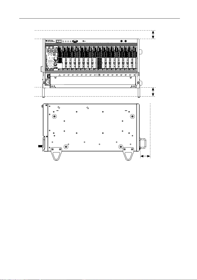
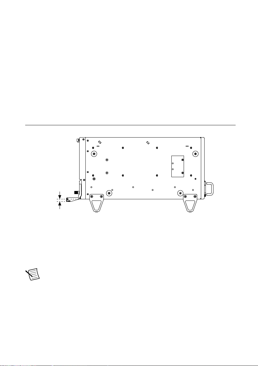
The following figures show the PXIe-1086DC chassis dimensions. The holes shown are for
the installation of the optional rack mount kits. You can install those kits on the front or rear of
the chassis, depending on which end of the chassis you want to face toward the front of the
instrument cabinet. Notice that the front and rear chassis mounting holes (size M4) are
symmetrical.
PXIe-1086DC User Manual and Specifications | © National Instruments | 41
Page 42

Figure 21. PXIe-1086DC Chassis Dimensions (Front and Side)
Dimensions are in inches (millimeters)
0.50
(12.7)
17.50 (444.5)
0.39
(9.9)
1.84
(46.8)
8.73
(221.9)
2.09
(53.2)
1.23
(31.3)
10.70 (271.8)
1.82
(46.3)
1.82
(46.3)
1.84
(46.8)
3.54
(90.0)
5.57
(141.5)
0.84
(21.3)
0.75
(19.1)
2.13
(54.2)
10.10
(256.1)
17.80
(452.7)
14.35 (364.40)
NI PXIe-1086
3.5-6A
210-300VDC
ACT/
LINK
10/100
42 | ni.com | PXIe-1086DC User Manual and Specifications
Page 43

Figure 22. PXIe-1086DC Chassis Dimensions (Bottom)
Dimensions are in inches (millimeters)
0.18
(4.7)
PXIe-1086DC User Manual and Specifications | © National Instruments | 43
Page 44

Figure 23. NI Chassis Rack Mount Kit Components
NI PXIe-1086
COOLING CLEARANCE REQUIRED. SEE MANUAL.
3
2
1
1. Front Rack Mount Kit
2. PXIe-1086DC Chassis
3. Rear Rack Mount Kit
Safety Compliance Standards
This product is designed to meet the requirements of the following electrical equipment safety
standards for measurement, control, and laboratory use:
• IEC 61010-1, EN 61010-1
• UL 61010-1, CSA C22.2 No. 61010-1
Note For UL and other safety certifications, refer to the product label or the
Electromagnetic Compatibility
This product meets the requirements of the following EMC standards for electrical equipment
for measurement, control, and laboratory use:
• EN 61326-1 (IEC 61326-1): Class A emissions; Basic immunity
• EN 55011 (CISPR 11): Group 1, Class A emissions
• AS/NZS CISPR 11: Group 1, Class A emissions
44 | ni.com | PXIe-1086DC User Manual and Specifications
Product Certifications and Declarations section.
Page 45

• FCC 47 CFR Part 15B: Class A emissions
• ICES-003: Class A emissions
Note In the United States (per FCC 47 CFR), Class A equipment is intended for
use in commercial, light industrial, and heavy industrial locations. In Europe,
Canada, Australia, and New Zealand (per CISPR 11), Class A equipment is intended
for use only in heavy industrial locations.
Note Group 1 equipment (per CISPR 11) is any industrial, scientific, or medical
equipment that does not intentionally generate radio frequency energy for the
treatment of material or inspection/analysis purposes.
Note For EMC declarations and certifications and additional information, refer to
the Product Certifications and Declarations section
CE Compliance
This product meets the essential requirements of applicable European Directives, as follows:
• 2014/35/EC; Low-Voltage Directive (safety)
• 2014/13/EC; Electromagnetic Compatibility Directive (EMC)
Product Certifications and Declarations
Refer to the product Declaration of Conformity (DoC) for additional regulatory compliance
information. To obtain product certifications and the DoC for NI products, visit ni.com/
product-certifications, search by model number, and click the appropriate link.
Environmental Management
NI is committed to designing and manufacturing products in an environmentally responsible
manner. NI recognizes that eliminating certain hazardous substances from our products is
beneficial to the environment and to NI customers.
For additional environmental information, refer to the Commitment to the Environment web
page at ni.com/environment. This page contains the environmental regulations and directives
with which NI complies, as well as other environmental information not included in this
document.
电子信息产品污染控制管理办法(中国 RoHS)
中国客户 National Instruments 符合中国电子信息产品中限制使用某些有害物
质指令(RoHS)。关于 National Instruments 中国 RoHS 合规性信息,请登录
ni.com/environment/rohs_china。(For information about China RoHS
compliance, go to ni.com/environment/rohs_china.)
Waste Electrical and Electronic Equipment (WEEE)
EU Customers At the end of the product life cycle, all NI products must be
disposed of according to local laws and regulations. For more information about
how to recycle NI products in your region, visit ni.com/environment/weee.
PXIe-1086DC User Manual and Specifications | © National Instruments | 45
Page 46

Pinouts
System Controller Slot XP1 Connector Pinout
Pins Signals
A GND
B 12V
C 12V
D GND
E 5V
F 3.3V
G GND
System Controller Slot XP2 Connector Pinout
Pin A B ab C D cd E F ef
1 2PETp1 2PETn1 GND 2PERp1 2PERn1 GND 2PETp2 2PETn2 GND
2 2PETp3 2PETn3 GND 2PERp3 2PERn3 GND 2PERp2 2PERn2 GND
3 2PETp4 2PETn4 GND 2PERp4 2PERn4 GND 2PETp5 2PETn5 GND
4 2PETp6 2PETn6 GND 2PERp6 2PERn6 GND 2PERp5 2PERn5 GND
5 2PETp7 2PETn7 GND 2PERp7 2PERn7 GND 2PETp8 2PETn8 GND
6 2PETp9 2PETn9 GND 2PERp9 2PERn9 GND 2PERp8 2PERn8 GND
7 2PETp10 2PETn10 GND 2PERp10 2PERn10 GND 2PETp11 2PETn11 GND
8 2PETp12 2PETn12 GND 2PERp12 2PERn12 GND 2PERp11 2PERn11 GND
9 2PETp13 2PETn13 GND 2PERp13 2PERn13 GND 2PETp14 2PETn14 GND
10 2PETp15 2PETn15 GND 2PERp15 2PERn15 GND 2PERp14 2PERn14 GND
46 | ni.com | PXIe-1086DC User Manual and Specifications
Page 47

System Controller Slot XP3 Connector Pinout
Pin A B ab C D cd E F ef
1 RSV RSV GND RSV RSV GND RSV RSV GND
2 RSV RSV GND PWR_OK PS_ON# GND LINKCAP PWRBTN# GND
3 SMBDAT SMBCLK GND RSVD RSVD GND RSVD RSVD GND
4 RSV PERST# GND 2RefClk+ 2RefClk- GND 1RefClk+ 1RefClk- GND
5 1PETp0 1PETn0 GND 1PERp0 1PERn0 GND 1PETp1 1PETn1 GND
6 1PETp2 1PETn2 GND 1PERp2 1PERn2 GND 1PERp1 1PERn1 GND
7 1PETp3 1PETn3 GND 1PERp3 1PERn3 GND 1PETp4 1PETn4 GND
8 1PETp5 1PETn5 GND 1PERp5 1PERn5 GND 1PERp4 1PERn4 GND
9 1PETp6 1PETn6 GND 1PERp6 1PERn6 GND 1PETp7 1PETn7 GND
10 2PETp0 2PETn0 GND 2PERp0 2PERn0 GND 1PERp7 1PERn7 GND
System Controller Slot XP4 Connector Pinout
Pin Z A B C D E F
1 GND GA4 GA3 GA2 GA1 GA0 GND
2 GND 5Vaux GND SYSEN# WAKE# ALERT# GND
3 GND RSV RSV RSV RSV RSV GND
4 GND RSV RSV RSV RSV RSV GND
5 GND PXI_TRIG3 PXI_TRIG4 PXI_TRIG5 GND PXI_TRIG6 GND
6 GND PXI_TRIG2 GND RSV PXI_STAR PXI_CLK10 GND
7 GND PXI_TRIG1 PXI_TRIG0 RSV GND PXI_TRIG7 GND
8 GND RSV GND RSV RSV PXI_LBR6 GND
PXIe-1086DC User Manual and Specifications | © National Instruments | 47
Page 48

System Timing Slot TP1 Connector Pinout
Pin A B ab C D cd E F ef
1 *A3+ *A3- GND *C7+ *C7- GND *C12+ *C12- GND
2 *C4+ *C4- GND PXI_STAR12 PXI_STAR13 GND *A12+ *A12- GND
3 *B4+ *B4- GND *A16+ *A16- GND *B12+ *B12- GND
4 *4A+ *A4- GND *B7+ *B7- GND *C13+ *C13- GND
5 *C5+ *C5- GND PXI_STAR14 PXI_STAR15 GND *A13+ *A13- GND
6 *B5+ *B5- GND *B16+ *B16- GND *B13+ *B13- GND
7 *A5+ *A5- GND *A7+ *A7- GND *C14+ *C14- GND
8 *C6+ *C6- GND PXI_STAR16 RSV GND *A14+ *A14- GND
9 *B6+ *B6- GND *C15+ *C15- GND *B14+ *B14- GND
10 *A6+ *A6- GND *B15+ *B15- GND *A15+ *A15- GND
*PXIe_DSTAR
System Timing Slot TP2 Connector Pinout
Pin A B ab C D cd E F ef
1 *C0+ *C0- GND *C8+ *C8- GND *B8+ *B8- GND
2 *A0+ *A0- GND *C9+ *C9- GND *A8+ *A8- GND
3 *B0+ *B0- GND *C1+ *C1- GND *A9+ *A9- GND
4 *B1+ *B1- GND PXI_STAR0 PXI_STAR1 GND *B9+ *B9- GND
5 *A1+ *A1- GND PXI_STAR2 PXI_STAR3 GND *C10+ *C10- GND
6 *C2+ *C2- GND PXI_STAR4 PXI_STAR5 GND *A10+ *A10- GND
7 *B2+ *B2- GND PXI_STAR6 PXI_STAR7 GND *B10+ *B10- GND
8 *A2+ *A2- GND PXI_STAR8 PXI_STAR9 GND *C11+ *C11- GND
9 *C3+ *C3- GND PXI_STAR10 PXI_STAR11 GND *A11+ *A11- GND
10 *B3+ *B3- GND *D16+ *D16- GND *B11+ *B11- GND
*PXIe_DSTAR
48 | ni.com | PXIe-1086DC User Manual and Specifications
Page 49

System Timing Slot XP3 Connector Pinout
Pin A B ab C D cd E F ef
1 *CLK100+ *CLK100- GND *SYNC100+ *SYNC100- GND **C+ **C- GND
2 PRSNT# PWREN# GND *DSTARB+ *DSTARB- GND **A+ **A- GND
3 SMBDAT SMBCLK GND RSV RSV GND RSV RSV GND
4 MPWRGD* PERST# GND RSV RSV GND 1RefClk+1RefClk- GND
5 1PETp0 1PETn0 GND 1PERp0 1PERn0 GND 1PETp1 1PETn1 GND
6 1PETp2 1PETn2 GND 1PERp2 1PERn2 GND 1PERp1 1PERn1 GND
7 1PETp3 1PETn3 GND 1PERp3 1PERn3 GND 1PETp4 1PETn4 GND
8 1PETp5 1PETn5 GND 1PERp5 1PERn5 GND 1PERp4 1PERn4 GND
9 1PETp6 1PETn6 GND 1PERp6 1PERn6 GND 1PETp7 1PETn7 GND
10 RSV RSV GND RSV RSV GND 1PERp7 1PERn7 GND
*PXIe_
**PXIe_DSTAR
System Timing Slot XP4 Connector Pinout
Pin Z A B C D E F
1 GND GA4 GA3 GA2 GA1 GA0 GND
2 GND 5Vaux GND SYSEN# WAKE# ALERT# GND
3 GND 12V 12V GND GND GND GND
4 GND GND GND 3.3V 3.3V 3.3V GND
5 GND PXI_TRIG3 PXI_TRIG4 PXI_TRIG5 GND PXI_TRIG6 GND
6 GND PXI_TRIG2 GND ATNLED PXI_CLK10_IN PXI_CLK10 GND
7 GND PXI_TRIG1 PXI_TRIG0 ATNSW# GND PXI_TRIG7 GND
8 GND PXIe_SYNC_CTRL GND RSV PXI_LBL6 PXI_LBR6 GND
PXIe-1086DC User Manual and Specifications | © National Instruments | 49
Page 50

Hybrid Slot P1 Connector Pinout
Pin Z A B C D E F
25 GND 5V REQ64# ENUM# 3.3V 5V GND
24 GND AD[1] 5V V(I/O) AD[0] ACK64# GND
23 GND 3.3V AD[4] AD[3] 5V AD[2] GND
22 GND AD[7] GND 3.3V AD[6] AD[5] GND
21 GND 3.3V AD[9] AD[8] M66EN C/BE[0]# GND
20 GND AD[12] GND V(I/O) AD[11] AD[10] GND
19 GND 3.3V AD[15] AD[14] GND AD[13] GND
18 GND SERR# GND 3.3V PAR C/BE[1]# GND
17 GND 3.3V IPMB_SCL IPMB_SDA GND PERR# GND
16 GND DEVSEL# GND V(I/O) STOP# LOCK# GND
15 GND 3.3V FRAME# IRDY# BD_SEL# TRDY# GND
12 to 14 Key Area
11 GND AD[18] AD[17] AD[16] GND C/BE[2]# GND
10 GND AD[21] GND 3.3V AD[20] AD[19] GND
9 GND C/BE[3]# IDSEL AD[23] GND AD[22] GND
8 GND AD[26] GND V(I/O) AD[25] AD[24] GND
7 GND AD[30] AD[29] AD[28] GND AD[27] GND
6 GND REQ# GND 3.3V CLK AD[31] GND
5 GND BRSVP1A5 BRSVP1B5 RST# GND GNT# GND
4 GND IPMB_PWR HEALTHY# # V(I/O) INTP INTS GND
3 GND INTA# INTB# INTC# 5V INTD# GND
2 GND TCK 5V TMS TDO TDI GND
1 GND 5V -12 TRST# +12 5V GND
50 | ni.com | PXIe-1086DC User Manual and Specifications
Page 51

Where to Go for Support
The National Instruments Web site is your complete resource for technical support. At ni.com/
support you have access to everything from troubleshooting and application development self-
help resources to email and phone assistance from NI Application Engineers.
A Declaration of Conformity (DoC) is our claim of compliance with the Council of the
European Communities using the manufacturer’s declaration of conformity. This system
affords the user protection for electromagnetic compatibility (EMC) and product safety. You
can obtain the DoC for your product by visiting ni.com/certification. If your product supports
calibration, you can obtain the calibration certificate for your product at ni.com/calibration.
National Instruments corporate headquarters is located at 11500 North Mopac Expressway,
Austin, Texas, 78759-3504. National Instruments also has offices located around the world to
help address your support needs. For telephone support in the United States, create your
service request at ni.com/support and follow the calling instructions or dial 512 795 8248. For
telephone support outside the United States, visit the Worldwide Offices section of ni.com/
niglobal to access the branch office Web sites, which provide up-to-date contact information,
support phone numbers, email addresses, and current events.
PXIe-1086DC User Manual and Specifications | © National Instruments | 51
Page 52

Information is subject to change without notice. Refer to the NI Trademarks and Logo Guidelines at ni.com/trademarks for
information on NI trademarks. Other product and company names mentioned herein are trademarks or trade names of their
respective companies. For patents covering NI products/technology, refer to the appropriate location: Help»Patents in your
software, the patents.txt file on your media, or the National Instruments Patent Notice at ni.com/patents. You can find
information about end-user license agreements (EULAs) and third-party legal notices in the readme file for your NI product. Refer
to the Export Compliance Information at ni.com/legal/export-compliance for the NI global trade compliance policy and how
to obtain relevant HTS codes, ECCNs, and other import/export data. NI MAKES NO EXPRESS OR IMPLIED WARRANTIES AS
TO THE ACCURACY OF THE INFORMATION CONTAINED HEREIN AND SHALL NOT BE LIABLE FOR ANY ERRORS. U.S.
Government Customers: The data contained in this manual was developed at private expense and is subject to the applicable
limited rights and restricted data rights as set forth in FAR 52.227-14, DFAR 252.227-7014, and DFAR 252.227-7015.
© 2019 National Instruments. All rights reserved.
377983A-01 July 12, 2019
 Loading...