

Page 1

™
PXI
PXI-8150B Series User Manual
PXI-8150B Series User Manual
February 1999 Edition
Part Number 322321A-01
Page 2

Worldwide Technical Support and Product Information
http://www.natinst.com
National Instruments Corporate Headquarters
11500 North Mopac Expressway Austin, Texas 78759-3504 USA Tel: 512 794 0100
Worldwide Offices
Australia 03 9879 5166, Austria 0662 45 79 90 0, Belgium 02 757 00 20, Brazil 011 284 5011,
Canada (Ontario) 905 694 0085, Canada (Québec) 514 694 8521, Denmark 45 76 26 00,
Finland 09 725 725 11, France 0 1 48 14 24 24, Germany 089 741 31 30, Hong Kong 2645 3186,
India 91805275406, Israel 03 6120092, Italy 02 413091, Japan 03 5472 2970, Korea 02 596 7456,
Mexico (D.F.) 5 280 7625, Mexico (Monterrey) 8 357 7695, Netherlands 0348 433466, Norway 32 84 84 00,
Singapore 2265886, Spain (Madrid) 91 640 0085, Spain (Barcelona) 93 582 0251, Sweden 08 587 895 00,
Switzerland 056 200 51 51, Taiwan 02 2377 1200, United Kingdom 01635 523545
For further support information, see the Customer Communication appendix of this manual.
© Copyright 1999 National Instruments Corporation. All rights reserved.
Page 3

Important Information
Warranty
The PXI-8150B Series of embedded PXI computers are warranted against defects in materials and workmanship for a
period of one year from the date of shipment, as evidenced by receipts or other documentation. National Instruments will,
at its option, repair or replace equipment that proves to be defective during the warranty period. This warranty includes
parts and labor.
The media on which you receive National Instruments software are warranted not to fail to execute programming
instructions, due to defects in materials and work man ship, for a peri od of 90 d ays from da te o f sh ipm ent, as evi denced
by receipts or other documentation. National Instruments will, at its option, repair or replace software media that do not
execute programming instructions if National Instruments receives noti ce of su ch defect s d uring th e warranty perio d.
National Instruments does not warrant that the op eration of t he soft ware shall b e uni nterrup ted or erro r free.
A Return Material Authorization (RMA) number must b e ob tain ed fro m th e facto ry an d clearl y mark ed on t he outsi de
of the package before any equipment will be a ccepted for warranty work. National Instruments will pay the shipping c osts
of returning to the owner parts which are covered by warran ty.
National Instruments believes that the information in this document is accurate. The document has been carefully
reviewed for technical accuracy. In the event that technical or typographical errors exist, National Instruments reserves
the right to make changes to subsequent editions of this document without prior notice to holders of this edition. The
reader should consult National Instruments if errors are suspected. In no event shall National Instruments be liable for
any damages arising out of or related to th is d ocum ent o r th e in form ation con tained in i t.
XCEPT AS SPECIFIED HEREIN
E
ANY WARRANTY OF MERCHANTABILITY OR FITNESS FOR A PARTICULAR PURPOSE
BY FAULT OR NEGLIGENCE ON THE PART OF NATIONAL INSTRUMENTS SHALL BE LIMITED TO THE AMOUNT THERETOFORE PAID BY THE
CUSTOMER
OR INCIDENTAL OR CONSEQUENTIAL DAMAGES, EVEN IF ADVISED OF THE POSSIBILITY THEREOF
National Instruments will apply regardless of the form of action, wh ether in con tract or tort , incl udin g n egli gen ce.
Any action against National Instruments must be brought within one year after the cause of action accrues. National
Instruments shall not be liable for any delay in performance due to causes beyond its reasonable control. The warranty
provided herein does not cover damages, defects, malfuncti ons, or s ervice failur es caused by own er’s fai lure to fol low
the National Instruments installation, operation, or maintenance instructions; owner’s modification of the product;
owner’s abuse, misuse, or negligent acts; and power failure or surges, fire, flood, accident, actions of third parties,
or other events outside reasonable control.
ATIONAL INSTRUMENTS WILL NOT BE LIABLE FOR DAMAGES RESULTING FROM LOSS OF DATA, PROFITS, USE OF PRODUCTS
. N
ATIONAL INSTRUMENTS MAKES NO WARRANTIES, EXPRESS OR IMPLIED, AND SPECIFICALLY DISCLAIMS
, N
USTOMER’S RIGHT TO RECOVER DAMAGES CAUSED
. C
. This limitation of the liability of
,
Copyright
Under the copyright laws, this publication may not be reproduced or transmitted in any form, electronic or mechanical,
including photocopying, recording, storing in an information retrieval system, or translating, in whole or in part, without
the prior written consent of National Instruments Corporation.
Trademarks
CVI™, LabVIEW™, NI-488.2™, NI-488.2M™, NI-DAQ™, NI-VISA™, PXI™, and TNT4882C™ are trademarks of
National Instruments Corporation.
Product and company names mentioned herein are trademarks or trade names of their respective companies.
WARNING REGARDING MEDICAL AND CLINICAL USE OF NATIONAL INSTRUMENTS PRODUCTS
National Instruments products are not designed with com ponent s and tes ting inten ded to ensure a l evel of reliab ilit y
suitable for use in treatment and diagnosis of humans. Applications of National Instruments products invol ving m edical
or clinical treatment can create a potential for accidental injury caused by product failure, or by errors on the part of the
user or application designer. Any use or application of National Instruments products for or involving medical or clinical
treatment must be performed by properly trained and qualified medical personnel, and all traditional medical safeguards,
equipment, and procedures that are appropriate in the particular situation to prevent serious injury or death should always
continue to be used when National Instruments products are being used . National Instrum ents product s are NOT intended
to be a substitute for any form of established process, procedure, or equipment used to monitor or safeguard human health
and safety in medical or clinical treatment.
Page 4

Compliance
FCC/DOC Radio Frequency Interference Class A Compliance
This equipment generates and uses radio frequency energy and, if not installed and used in strict accordance
with the instructions in this manual, may cause interference to radio and television reception. Classification
requirements are the same for the Federal Communications Commission (FCC) and the Canadian
Department of Communications (DOC). This equipment has been tested and found to comply with the
following two regulatory agencies:
Federal Communications Commission
This equipment has been tested and found to comply with the limits for a Class A digital device, pursuant to
part 15 of the FCC Rules. These limits are designed to provide reasonable protection against harmful
interference when the equipment is operated in a commercial environment. This equipment generates, uses,
and can radiate radio frequency energy and, if not installed and used in accordance with the instruction
manual, may cause harmful interference to radio communications. Operation of this equipment in a
residential area is likely to cause harmful interference in which case the user will be required to correct the
interference at his own expense.
Notices to User: Changes or modifications not expressly approved by National Instruments could void
If necessary, consult National Instruments or an experienced radio/television technician for additional
suggestions. The following booklet prepared by the FCC may also be helpful: Interference to Home
Electronic Entertainment Equipment Handbook. This booklet is available from the U.S. Government
Printing Office, Washington, DC 20402.
the user’s authority to operate the equipment under the FCC Rules.
This device complies with the FCC rules only if used with shielded interface cables
of suitable quality and construction. National Instruments used such cables to test
this device and provides them for sale to the user. The use of inferior or nonshielded
interface cables could void the user’s authority to operate the equipment under the
FCC rules.
Canadian Department of Communications
This Class A digital apparatus meets all requirements of the Canadian Interference-Causing Equipment
Regulations.
Cet appareil numérique de la classe A respecte toutes les exigences du Règlement sur le matériel brouilleur
du Canada.
Page 5

Contents
About This Manual
Organization of This Manual.........................................................................................ix
Conventions Used in This Manual.................................................................................x
How to Use This Documentation Set ............................................................................ xi
Acrobat (Online) Documentation....................................................................xi
Related Documentation........................................... .......................................................xi
Customer Communication................................... ..........................................................xii
Chapter 1
Introduction
Overview........................................................................................................................1-1
Hardware Description....................................................................................................1-3
Benefits of PXI................................................................................................1-3
PXI-8150B Series Design................................................................................1-3
PXI-8150B Series Models............................................................................... 1-4
Memory ...........................................................................................................1-4
System Slot Functionality................................................................................1-4
Custom Application-Specific Interface Chips.................................................1-5
Front Panel Features..................................................... ...................................1-5
Peripheral Expansion.......................................................................................1-6
PXI-1020 and PXI-1025 Chassis Support.......................................................1-7
Optional Equipment.......................................................................................................1-7
National Instruments Software ......................................................................................1-7
PXI-1020 Chassis..............................................................................1-7
Chapter 2
Functional Overview
PXI-8150B Functional Description ...............................................................................2-1
Chapter 3
PXI-8150B Series Configuration and Installation
Default Settings..............................................................................................................3-1
Configuring the PXI-8150B Series................................................................................3-4
Installed System RAM ....................................................................................3-4
System CMOS.................................................................................................3-4
Ethernet Power-on Defaults ............................................................................3-5
LCD Output (PXI-1020 Chassis) ....................................................................3-5
©
National Instruments Corporation v PXI-8150B Series User Manual
Page 6

Contents
LCD Resolution ..............................................................................................3-6
Keyboard and Mouse ......................................................................................3-6
Serial IRQ, INTP, and INTS...........................................................................3-7
Onboard Video................................................................................................3-8
Installing the PXI-8150B Series....................................................................................3-8
How to Remove the Unit from the PXI Mainframe........................................3-11
Chapter 4
BIOS
Entering BIOS Setup.............................. .......................................................................4-1
Default BIOS Setup Settings.........................................................................................4-1
Updating the BIOS........................................................................................................4-1
Appendix A
Specifications
Appendix B
PXI-8150B Series System Resources
Appendix C
LED Indicators
Appendix D
Front Panel and Connectors
Appendix E
Common Questions
Appendix F
Customer Communication
Glossary
Index
PXI-8150B Series User Manual vi
©
National Instruments Corporation
Page 7

Figures
Contents
Figure 1-1. PXI-8155B Embedded Computer .........................................................1-1
Figure 1-2. PXI-8156B Embedded Computer .........................................................1-2
Figure 2-1. PXI-8150B Series Block Diagram........................................................2-2
Figure 3-1. PXI-8150B Series I/O Board Parts Locator Diagram...........................3-3
Figure 3-2. PXI-8150B Series CPU Board Parts Locator Diagram.........................3-3
Figure 3-3. System CMOS.......................................................................................3-4
Figure 3-4. Ethernet Power-on Defaults ..................................................................3-5
Figure 3-5. LCD Output Settings.............................................................................3-5
Figure 3-6. LCD Resolution Setting ........................................................................3-6
Figure 3-7. Active Keyboard Port............................................................................3-6
Figure 3-8. Active Mouse Port .................................................................................3-6
Figure 3-9. INTP Configuration...............................................................................3-7
Figure 3-10. INTS Configuration...............................................................................3-7
Figure 3-11. Onboard Video................................................ ......................................3-8
Figure 3-12. PXI-8156B Installed in a PXI Mainframe.............................................3-10
Figure D-1. PXI-8155B Front Panel Layout and Dimensions..................................D-2
Figure D-2. PXI-8156B Front Panel Layout and Dimensions..................................D-3
Figure D-3. Keyboard and Mouse Connectors Location and Pinout........................D-4
Figure D-4. VGA Connector Location and Pinout...................................................D-5
Figure D-5. Ethernet Connector Location and Pinout ..............................................D-6
Figure D-6. COM1 and COM2 Connectors Location and Pinout ............................D-7
Figure D-7. Parallel Port Connector Location and Pinout........................................D-8
Figure D-8. GPIB Connector Location and Pinout...................................................D-10
Figure D-9. USB Connector Location and Pinout....................................................D-11
Figure D-10. PXI Connectors Location and Pinout....................................................D-12
©
National Instruments Corporation vii PXI-8150B Series User Manual
Page 8

Contents
Tables
Table 1-1. PXI-8150B Series Peripherals Overview .............................................1-6
Table 3-1. PXI-8150B Series Hardware Default Settings .....................................3-1
Table B-1. PXI-8150B Series ISA Interrupt Resource Allocations .......................B-1
Table B-2. PXI-8150B Series DMA Channel Resource Allocations ..................... B-2
Table B-3. PXI-8150B Series I/O Address Map ....................................................B-3
Table D-1. Keyboard and Mouse Connector Signals .............................................D-4
Table D-2. VGA Connector Signals ......................................................................D-5
Table D-3. Ethernet Connector Signals ..................................................................D-7
Table D-4. COM1 and COM2 Connector Signals .................................................D-8
Table D-5. Parallel Port Connector Signals ...........................................................D-9
Table D-6. GPIB Connector Signals ......................................................................D-10
Table D-7. USB Connector Signals .......................................................................D-11
Table D-8. P2 Connector Pinouts for the System Controller Slot .........................D-13
Table D-9. P1 Connector Pinouts for the System Controller Slot .........................D-14
PXI-8150B Series User Manual viii
©
National Instruments Corporation
Page 9

About This Manual
This manual contains detailed instructions for installing and configuring
your National Instruments PXI-8150B Series embedded computer kit.
The PXI-8150B Series includes all the models of the PXI-8155B and
PXI-8156B embedded PXI computers.
Organization of This Manual
This manual is organized as follows:
• Chapter 1, Introduction, describes the PXI-8150B Series of embedded
PXI computers and lists optional equipment and software.
• Chapter 2, Functional Overview, contains functional descriptions of
each major logic block on the PXI-8150B Series embedded computers.
• Chapter 3, PXI-8150B Series Configuration and Installation, contains
the instructions for configuring and installing the PXI-8150B Series
embedded computer.
• Chapter 4, BIOS, contains information on BIOS, the low-level
interface between the hardware and PC software that configures and
tests your hardware when you start up the system.
• Appendix A, Specifications, lists the electrical, mechanical, and
environmental specifications of the PXI-8150B Series embedded
computer, and describes how to add RAM.
• Appendix B, PXI-8150B Series System Resources, describes the
system resources available on the PXI-8150B Series embedded
computer and where they are allocated.
• Appendix C, LED Indicators, describes how to interpret the status of
the PXI-8150B Series computer by reading the LEDs on the front
panel.
• Appendix D, Front Panel and Connectors, describes the front panel
and connectors on the PXI-8150B Series embedded computer.
• Appendix E, Common Questions, answers common questions you
may have when using the PXI-8150B Series embedded computer.
• Appendix F, Customer Communication, contains forms you can use to
request help from National Instruments or to comment on our products
and manuals.
©
National Instruments Corporation ix PXI-8150B Series User Manual
Page 10

About This Manual
• The Glossary contains an alphabetical list and description of terms
used in this manual, including abbreviations, acronyms, metric
prefixes, mnemonics, and symbols.
• The Index contains an alphabetical list of key terms and topics used in
this manual, including the page where you can find each one.
Conventions Used in This Manual
The following conventions are used in this manual:
< > Angle brackets enclose the name of a key on the keyboard (for
example, <DEL>).
This icon to the left of bold italicized text denotes a note, which alerts you
to important information.
!
bold Bold text denotes the names of menus, menu items, dialog box buttons or
bold italic Bold italic text denotes a note, caution, or warning.
bold monospace Bold text in this font denotes the messages and responses that the computer
italic Italic text denotes emphasis, a cross reference, or an introduction to a key
monospace T ext in this font denotes the proper names of disk dri ves, paths, directories,
PXI-8150B Series The terms PXI-8150B Series and PXI-8150B refer to a series of 3U PXI
This icon to the left of bold italicized text denotes a caution, which advises
you of precautions to take to avoid injury, data loss, or a system crash.
This icon to the left of bold italicized text denotes a warning, which advises
you of precautions to take to avoid being electrically shocked.
options, or LEDs.
automatically prints to the screen.
concept.
filenames, and extensions.
controllers. Currently, this series consists of the PXI-8155B and
PXI-8156B, with various processors and in different speeds.
PXI-8150B Series User Manual x
©
National Instruments Corporation
Page 11

How to Use This Documentation Set
Begin by reading Getting Started with Your PXI-8150B Series for
Windows NT/98, a brief quick-start manual that describes how to set up and
get started with your kit using the default settings.
This manual, the PXI-8150B Series User Manual, contains more details
about changing the installation or configuration from the defaults, and
about using the hardware.
PXI-8156B users receive the NI-488.2M software kit, which includes
the NI-488.2M User Manual for Windows 95 and Windows NT and the
NI-488.2M Function Reference Manual for Win32.
If you ordered either LabVIEW or LabWindows/CVI, you received
full documentation along with a configuration disk to unlock and access
these application programming environments, which are already installed
on your hard drive.
Acrobat (Online) Documentation
To learn more about using NI-VISA your kit includes online manuals in the
form of Adobe Acrobat version 3.0 portable document format (PDF) files.
The Acrobat manuals and their installed locations are as follows.
• The NI-VISA User Manual describes how to program using NI-VISA:
Start»Programs»VXIpnp»NI-VISA User Manual
• The NI-VISA Programmer Reference Manual describes in detail the
attributes, events, and operations you use in NI-VISA:
Start»Programs»VXIpnp»NI-VISA Programmer
Reference Manual
About This Manual
If you do not have Adobe Acrobat Reader 3.0, you can download a copy
from the Adobe W eb site at
http://www.adobe.com/.
Related Documentation
The following documents contain information you may find helpful as you
read this manual:
• PICMG 2.0 R2.1 CompactPCI Specification, PCI Industrial
Computers Manufacturers Group
• IEEE Standard P1284.1-1997 (C/MM) Standard for Information
Technology for Transport Independent Printer/System Interface
©
National Instruments Corporation xi PXI-8150B Series User Manual
Page 12

About This Manual
• PCI Local Bus Specification, Revision 2.1, PCI Special Interest Gr oup
• PXI Specification, Revision 1.0, National Instruments Corporation
• Serialized IRQ Support for PCI Systems Specification, Revision 6.0,
Compaq Computer et al.
Customer Communication
National Instruments wants to receive your comments on our products
and manuals. We are interested in the applications you develop with
our products, and we want to help if you have problems with them.
To make it easy for you to contact us, this manual contains comment and
configuration forms for you to complete. These forms are in Appendix F,
Customer Communication, at the end of this manual.
PXI-8150B Series User Manual xii
©
National Instruments Corporation
Page 13
Introduction
This chapter describes the PXI-8150B Series of embedded PXI computers
and lists optional equipment and software.
Overview
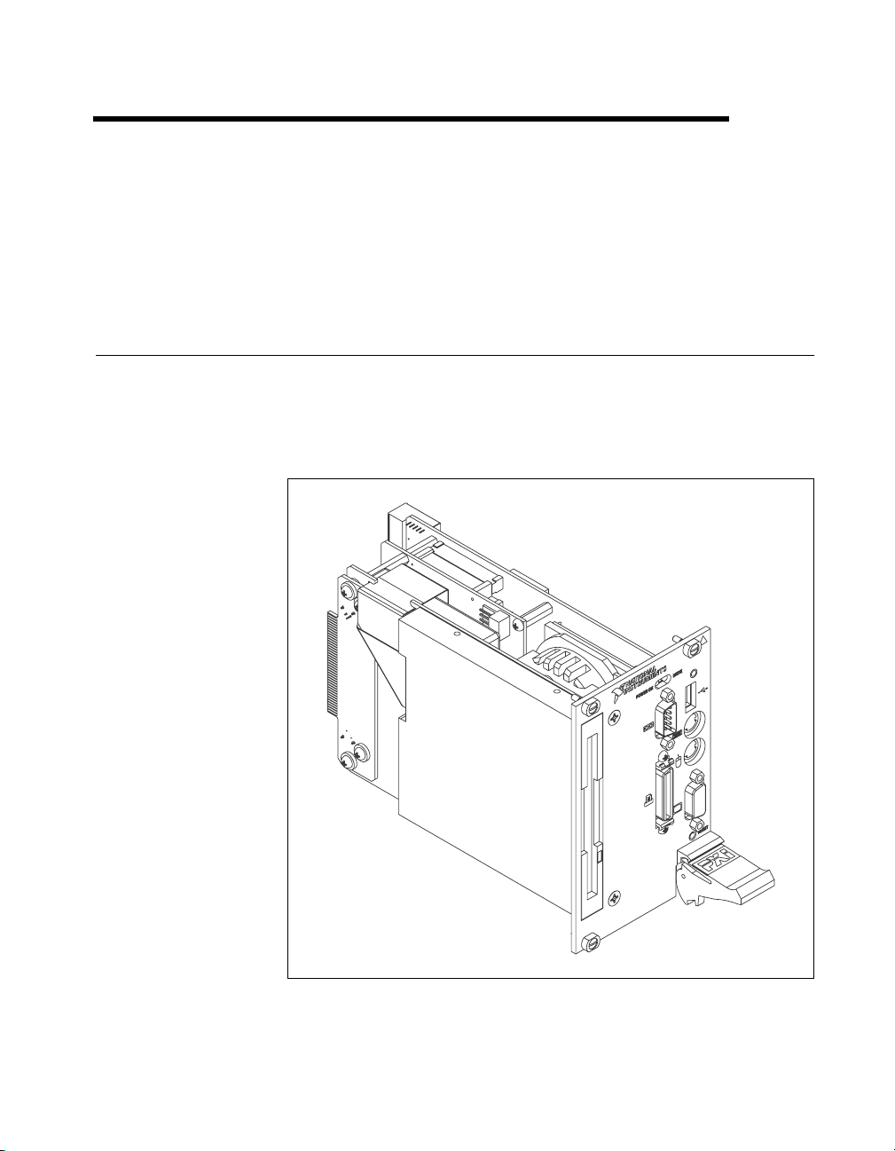
The PXI-8150B Series consists of the PXI-8155B and the PXI-8156B PXI
system controllers, as shown in the following illustrations. Refer to
Appendix D, Front Panel and Connectors, to determine the purpose for
each connector on the module. Figure 1-1 shows a PXI-8155B model.
1
Figure 1-1.
©
National Instruments Corporation 1-1 PXI-8150B Series User Manual
PXI-8155B Embedded Computer
Page 14
Chapter 1 Introduction
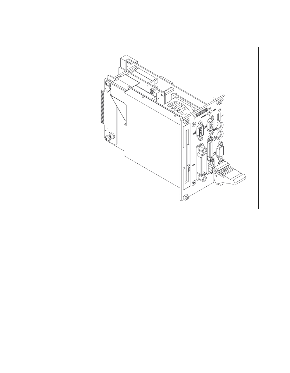
Figure 1-2 shows a PXI-8156B model.
Figure 1-2. PXI-8156B Embedded Computer
The PXI-8150B Series controllers are 3U PXI/CompactPCI embedded
computers based on the Peripheral Component Interface (PCI) bus
and Industry Standard Architecture (ISA). These computers are
high-performance, easy-to-use platforms for controlling PCI systems,
featuring complete PXI (PCI eXtensions for Instrumentation) functionality
through interactive utilities and C function calls. In addition, the
PXI-8156B has Ethernet capability plus an IEEE 488.2 interface that is
compatible with the NI-488.2 architecture.
The PXI-8150B Series is a custom computer that you install directly in the
system controller slot of your PXI mainframe. An embedded computer can
take full advantage of the PXI high-performance backplane capabilities.
PXI-8150B Series User Manual 1-2
©
National Instruments Corporation
Page 15

All models in the PXI-8150B Series are compatible with PC-compatible
software tools, the National Instruments LabVIEW and LabWindows/CVI
application software, and the NI-VISA, NI-488.2M, and NI-DAQ software.
Hardware Description
Benefits of PXI
The PXI-8150B Series PXI/CompactPCI embedded computers are
high-performance CompactPCI-compatible system controllers that are
compatible with the PXI bus specification. PXI defines a compact modular
PC platform for industrial instrumentation. PXI leverages the PCI bus,
which is the de facto standard for today’s desktop computer software and
hardware designs. As a result, PXI users receive all the benefits of PCI
within an architecture that supports mechanical, electrical, and software
features tailored to industrial instrumentation, data acquisition, and
automation applications.
Well-suited for industrial applications, PXI leverages from the
CompactPCI specification, which defines a rugged form factor for PCI that
offers superior mechanical integrity and easy installation and removal of
hardware components. PXI products offer higher and more carefully
defined levels of environmental perfo rmance required by the vibration,
shock, temperature, and humidity extremes of industrial environments.
PXI adds mandatory environmental testing and active cooling to the
CompactPCI mechanical specification to ease system integration and
ensure multivendor interoperability.
Chapter 1 Introduction
Additionally, PXI meets the more specific needs of instrumentation users
by adding an integrated trigger bus and reference clock for multiple-board
synchronization, a star trigger bus for very precise timing, and local buses
for side-band communication between adjacent peripherals.
PXI-8150B Series Design
The PXI-8150B Series PXI embedded computers are high-performance
PXI system controllers with all the standard I/O features built in. The
PXI-8150B Series uses state-of-the-art technology and packaging to create
a fully PC-compatible controller for PXI. Due to the unique design and
packaging, these computers have onboard PCI video and are still able to
connect to the PXI bus without the need of a PCI-to-PCI bridge. As a result,
they preserve the full 132 Mbytes/s PCI bandwid th for other PXI boards. In
addition, the PXI-8150B supports masters in all seven available PXI slots.
©
National Instruments Corporation 1-3 PXI-8150B Series User Manual
Page 16

Chapter 1 Introduction
The PXI-8150B Series design includes many standard PC peripherals,
which means you can install your custom-designed peripheral devices in all
PXI slots. It also has two user-accessible SO-DIMM sockets so it is easy to
upgrade memory. The unique packaging includes a built-in 1.44 MB floppy
drive and 2.5 in. hard drive. The mechanical assembly of the PXI-8150B
mounts these devices to the PXI-8150B main board so you can remove the
entire unit intact. This eases integration issues and cabling. The PXI-8150B
plugs directly into the system controller slot and expands to the left, thus
preserving all usable PXI slots for user-defined peripheral devices.
PXI-8150B Series Models
Currently the PXI-8150B Series consists of two models—the PXI-8155B
and the PXI-8156B. Both models have two CPU choices—a 233 MHz or
333 MHz MMX processor.
The models differ in the front-panel I/O. The PXI-8155B comes complete
with a 3.5 in. 1.44 MB floppy drive, 4 GB hard dri ve or larger, Super VGA
with 2 MB SGRAM, a serial port, an IEEE 1284 parallel port, a PS/2
keyboard and mouse, a USB connector, and software installed. The
PXI-8156B adds a second serial port, a 10BaseT Ethernet port, and an
IEEE 488.2 (GPIB) interface compatible with the National Instruments
AT-GPIB/TNT.
Memory
The PXI-8150B and its memory sockets are easily accessible so you can
install additional DRAM in the field. You can install up to 256 MB of
10 ns SDRAM, using 144-pin SO-DIMMS.
The PXI-8150B contains at least a 4 GB internal, enhanced IDE hard disk.
For information on adding RAM by installing SO-DIMMs, refer to
Appendix A, Specifications.
System Slot Functionality
You can use the PXI-8150B Series computers to achieve full PXI system
slot control of your PXI system. In the system slot, the PXI-8150B provides
master/slave capabilities to all slots in the PXI system.
PXI-8150B Series User Manual 1-4
©
National Instruments Corporation
Page 17

Custom Application-Specific Interface Chips
The PXI-8156B has the TNT4882C custom ASIC to give full GPIB control
of external instruments via a front-panel connector. GPIB capability is fully
compatible with IEEE 488.2 and the industry-standard NI-488.2M driver
for a variety of operating systems.
Front Panel Features
The PXI-8150B Series has the following front-panel features:
• Internal 3.5 in. floppy drive
• System reset push-button
• Front-panel connectors:
– RS-232 Serial (one on PXI-8155B, two on PXI-8156B)
– Extended Capabilities Parallel (ECP)
– VGA Controller
– Universal Serial Bus (USB)
– PS/2-style keyboard
– PS/2-style mouse
– GPIB (PXI-8156B only)
– 10BaseT Ethernet (PXI-8156B only)
• Two front-panel LEDs that show PC status
– POWEROK LED indicates that the power is on and reset is no
longer asserted.
– DRIVE LED indicates when an access to the internal hard disk is
occurring.
• Two front-panel LEDs that show Ethernet port status (PXI-8156B
Series only)
– TX/RX LED indicates that the PXI-8156B is receiving or
transmitting a packet of data through its Ethernet port.
– LINK LED indicates periodic link test passed.
Chapter 1 Introduction
©
National Instruments Corporation 1-5 PXI-8150B Series User Manual
Page 18

Chapter 1 Introduction
Peripheral Expansion
The PXI-8150B uses the PCI local bus and ISA bus for peripheral
expansion. The PCIbus is a 32-bit multimaster bus that achieves a top
throughput of 132 Mbytes/s and can handle numerous peripherals. The ISA
bus is the legacy peripheral bus found on current and older PCs.
For information on installing and configuring these peripherals for use with
the PXI-8150B, refer to the
drivers.txt file explains ho w to install support for each peripheral. This
directory also contains manufacturers’ documentation for the peripherals.
Also refer to the
T able 1-1 lists the various peripherals and describes the external connector,
its bus interface, and its function.
C:\Images\Pxi815xB directory. The
readme files for the most up-to-date information.
Table 1-1.
External
Peripheral
Connector
Video 15-pin DSUB
(standard VGA)
PXI-8150B Series Peripherals Overview
ISA
or PCI
PCI High-resolution/ color support for a
Super VGA monitor
Function
IDE None PCI Supports internal fast ATA-3 hard drive
Ethernet RJ-45 ISA 10BaseT Ethernet connection
GPIB 24-pin standard
GPIB connector
Serial Serial Port
ISA IEEE 488.2 interface compatible with the
National Instruments AT-GPIB/TNT
ISA 16550 serial ports
(9-pin DSUB)
Parallel Parallel Port
ISA Extended capabilities
(IEEE 1284)
USB 4-pin Series A
PCI Universal Serial Bus
receptacle
Keyboard/Mouse PS/2 ISA PS/2-style keyboard and mouse
Watchdog Timer None ISA Indicates when timer is not refreshed
PXI-8150B Series User Manual 1-6
©
National Instruments Corporation
Page 19

PXI-1020 and PXI-1025 Chassis Support
The PXI-8150B Series controller is designed to directly interface to
PXI-1020 and PXI-1025 chassis. This interface contains the signals
required to control a TFT LCD, an IDE device, a PS/2 keyboard, and a
PS/2 mouse.
Because the keyboard/mouse controller on the PXI-8150B Series supports
only one keyboard and one mouse at a time, the controller has two switches
you can use to control whether to enable either the keyboard and mouse
ports on the front panel of the PXI-8150B or the built-in chassis devices.
Refer to the Keyboard and Mouse section in Chapter 3, PXI-8150B Series
Configuration and Installation, for switch settings.
PXI-1020 Chassis
The PXI-1020 chassis currently does not contain a built-in keyboard.
When using the PXI-8150B Series controller with the PXI-1020 chassis,
the LCD may be dimmed through software. The software is located on your
hard drive in the
chassis you can select whether the LCD is enabled while booting or off
until the operating system loads and software turns it on. Refer to the
LCD Output section in Chapter 3, PXI-8150B Series Configuration and
Installation, for the jumper settings.
C:\Images\PXI815xB\LCD directory. Also, with this
Chapter 1 Introduction
Optional Equipment
You can contact National Instruments to order the following optional
equipment:
• Enhanced parallel port adapter cable
• Single-shielded 2 m GPIB cable
National Instruments Software
National Instruments has developed several software kits that you can use
with the PXI-8150B Series. The software is already installed on your hard
drive.
The NI-488.2M software kit gives you access to the industry-standard
NI-488.2M software for controlling external GPIB instruments through the
GPIB port on the front panel of the PXI-8156B. The GPIB interface is fully
compatible with the NI-488.2M driver for a variety of operating systems.
©
National Instruments Corporation 1-7 PXI-8150B Series User Manual
Page 20

Chapter 1 Introduction
Any GPIB application using NI-488.2M or NI-VISA will run on the
PXI-8156B.
NI-DAQ has an extensive library of functions that you can call from your
application programming environment. These functions include routines
for analog input (A/D conversion), buffered data acquisition (high-speed
A/D conversion), analog output (D/A conversion), waveform generation,
digital I/O, counter/timer operations, SCXI, RTSI, self-calibration,
messaging, and acquiring data to extended memory.
NI-VISA is the National Instruments implementation of the VISA
specification. VISA is a uniform API for communicating and controlling
Serial, GPIB, PXI, VXI, and various other types of instruments. This API
aids in the creation of more portable applications and instrument drivers.
For information on writing your own PXI instrument driver with NI-VISA,
see the NI-VISA Getting Started manual and the
NI-VISA directory.
readme.txt file in the
You can also use the National Instruments LabVIEW and
LabWindows/CVI application programs and instrument drivers to ease
your programming task. These standardized programs match the modular
virtual instrument capability of PXI and can reduce your PXI software
development time. These programs feature extensive libraries of GPIB,
Serial, and VXI instrument drivers written to take full advantage of direct
PXI control. LabVIEW and LabWindo ws/CVI include all the tools needed
for instrument control, data acquisition, analysis, and presentation.
LabVIEW is a complete programming environment that departs from the
sequential nature of traditional programming languages and features a
graphical programming environment.
LabWindows/CVI is an interactive C development environment for
building test and measurement and instrument control systems. It includes
interactive code-generation tools and a graphical editor for b uilding custom
user interfaces.
PXI-8150B Series User Manual 1-8
©
National Instruments Corporation
Page 21

Functional Overview
This chapter contains functional descriptions of each major logic block on
the PXI-8150B Series embedded computers.
PXI-8150B Functional Description
The PXI-8150B is a modular PC in a PXI 3U-size form factor. It includes
many high-performance peripherals that normally require add-in cards on
desktop PCs.
2
©
National Instruments Corporation 2-1 PXI-8150B Series User Manual
Page 22
Chapter 2 Functional Overview
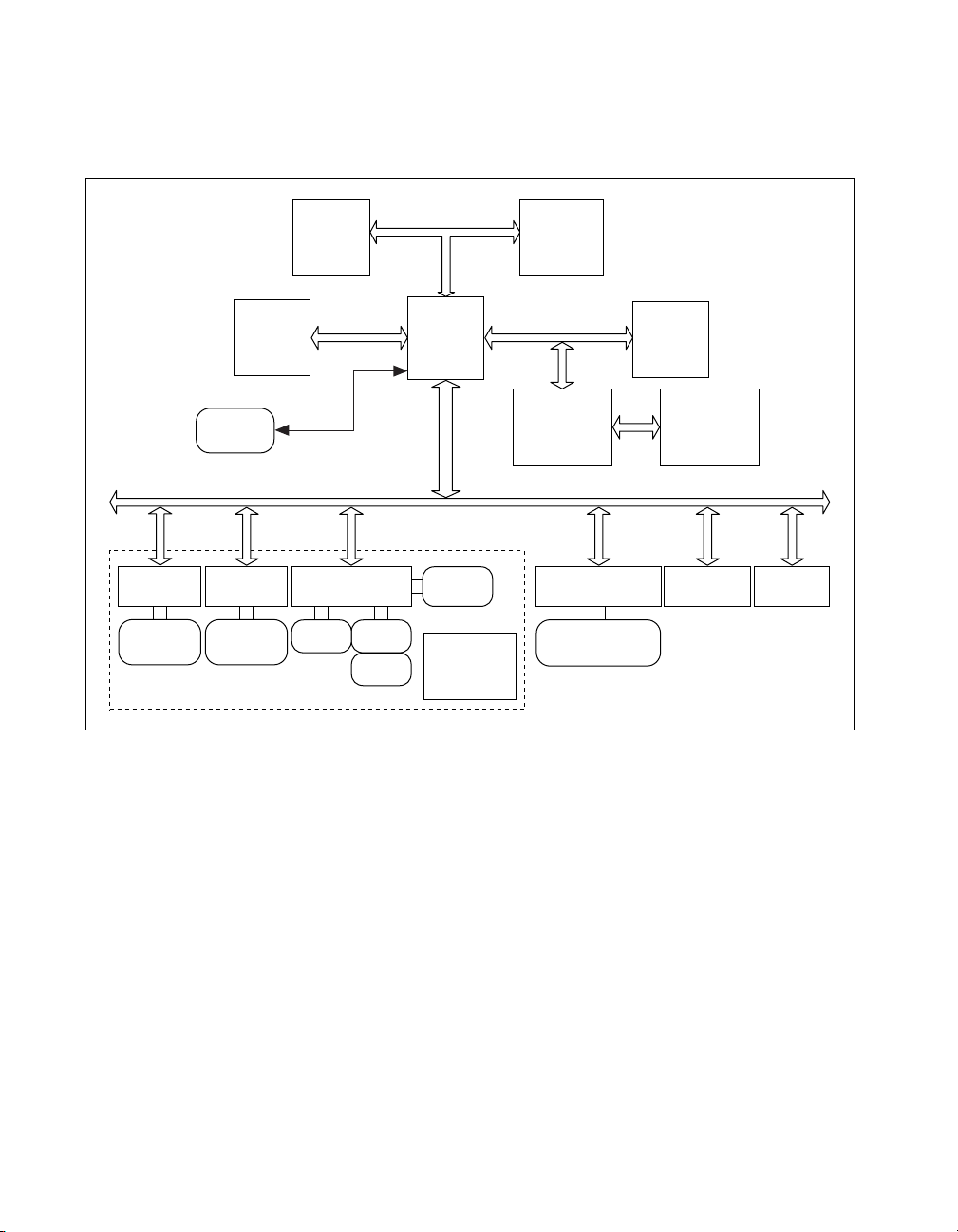
Figure 2-1 is a functional block diagram of the PXI-8150B Series.
Following the diagram is a description of each logic block shown.
Ethernet
10BaseT
RJ-45
Connector
SO-DIMM
SDRAM
USB
Connector
GPIB
GPIB
Connector
Socket 7
CPU
PC Peripherals
LPT 1 COM 1
COM 2
512 KB L2
Cache/Tag
RAM
Chip Set
Ultra DMA
33 IDE,
USB
I
S
A
B
u
s
Daughter Card
Internal
Floppy
Internal
2.5 in. HD
PCI Bus
PCI VIDEO
with 2 MB
SGRAM
Keyboard/Mouse
Controller
Keyboard/Mouse
Connector
PXI
Connector
Interface
BIOS/Real
Time Clock
Figure 2-1. PXI-8150B Series Block Diagram
TFT
LCD
Watchdog
Timer
The PXI-8150B consists of the following logic blocks on the CPU module
and the I/O (daughter card) module. The CPU module has the following
logic blocks:
• Socket 7 CPU is the socket definition for the Intel Pentium Processor
family.
• The L2 Cache/Tag block consists of 512 KB of Pipeline Burst SRAM.
• The SO-DIMM block consists of two 64-bit SDRAM sockets that can
hold up to 128 MB each.
• The Chip Set block consists of the chip set that connects the CPU to
cache and the DRAM. The chip set also contains the USB interface and
the IDE interface.
PXI-8150B Series User Manual 2-2
©
National Instruments Corporation
Page 23

Chapter 2 Functional Overview
• The PCI video circuitry is a PCI-based design that has a 64-bit data
path to up to 2 MB of SGRAM. It also contains a TFT LCD Interface
which is used in the National Instruments PXI-1020 and PXI-1025
chassis, and supports Windows 98 dual display: LCD and CRT.
• The USB connector connects the chip set to the Universal Serial Bus
interface.
• The PXI connector connects the PXI-8150B to the PXI/CompactPCI
backplane.
• The Keyboard/Mouse block contains the PS/2 keyboard and mouse
interface.
• The BIOS/RTC block contains the boot BIOS and the Real T ime Clock
interface.
• The Watchdog Timer block is the circuitry that, once configured,
signals if the timer is not refreshed. Refer to the
located in the
C:\Images\PXI815xB directory for more
drivers.txt file
information on configuring and using the watchdog timer.
The daughter card module has the following logic blocks:
• The Ethernet block on the PXI-8156B is an ISA-based Ethernet
circuit. It uses an RJ-45 connector for access to an external
Ethernet-based LAN.
• The GPIB logic block represents the IEEE 488.2 port on the
PXI-8156B model. It uses the National Instruments TNT4882 ASIC
for maximum performance as an ISA-based GPIB controller.
• The PC P eripherals blocks represent the other peripherals supplied by
the PXI-8150B Series. The PXI-8155B has one serial port, an
ECP/EPP parallel port, and a 1.44 MB, 3.5 in. floppy drive. The
PXI-8156B adds a second serial port.
• The IDE block is dedicated PCI-IDE circuitry providing fast ATA-3
transfers to the internal hard drive. The IDE feature is built into the
chip set.
©
National Instruments Corporation 2-3 PXI-8150B Series User Manual
Page 24

PXI-8150B Series
Configuration and Installation
This chapter contains the instructions for configuring and installing the
PXI-8150B Series embedded computer. Unless otherwise noted, these
instructions apply to all models in the PXI-8150B Series, which currently
consists of the PXI-8155B and the PXI-8156B.
3
Caution
!
Electrostatic discharge can damage several components on your PXI-8150B
module. T o avoid such damage in handling the module, touch the antistatic plastic
package to a metal part of your PXI mainframe before removing the module from
the package.
Default Settings
This section summarizes the hardware default settings for the PXI-8150B
Series for easy reference. The module is set at the factory for the most
commonly used configuration.
Table 3-1 lists the factory-default settings and options for the onboard
jumpers and switches. Five of the jumpers and two switches are located on
the CPU board, and three jumpers are on the I/O board.
Table 3-1.
Jumper/Switch Default Setting Optional Setting
W1 (CPU Board)
CMOS Clear
W2 (CPU Board)
INTP Connection
PXI-8150B Series Hardware Default Settings
Disabled (Normal
CMOS operation)
No Connection to
INTP
Clear CMOS
IRQ14
W3 (CPU Board)
INTS Connection
W14 (CPU Board)
Onboard video
©
National Instruments Corporation 3-1 PXI-8150B Series User Manual
Serial IRQ
Connected to INTS
Enabled Disabled
a. No Connection
b. IRQ15
Page 25

Chapter 3 PXI-8150B Series Configuration and Installation
Table 3-1. PXI-8150B Series Hardware Default Settings (Continued)
Jumper/Switch Default Setting Optional Setting
W17 (CPU Board)
LCD Resolution
S1 (CPU Board)
Active Keyboard
Port
S2 (CPU Board)
Active Mouse Port
W1 (I/O Board)
Ethernet EEPROM
(PXI-8156B only)
W3 (I/O Board)
LCD Display Output
on Boot
W4 (I/O Board)
LCD Display Output
on Boot
640 × 480 800 × 600
PXI-8150B
Controller Front
Chassis Keyboard
(if available)
Panel Keyboard Port
PXI-8150B
Controller Front
Chassis Mouse
(if available)
Panel Mouse Port
Enable Ethernet
EEPROM
Do not alter the
default setting.
configuration
ON OFF until software
enabled
ON OFF until software
enabled
PXI-8150B Series User Manual 3-2
©
National Instruments Corporation
Page 26

Chapter 3 PXI-8150B Series Configuration and Installation
Figures 3-1 and 3-2 show the location and factory-default settings of the
configuration switches and jumpers on the PXI-8150B Series.
1W1 2W3
Figure 3-1. PXI-8150B Series I/O Board Parts Locator Diagram
Figure 3-2 shows the CPU board.
1S1
2S2
3W17
1 5
Figure 3-2. PXI-8150B Series CPU Board Parts Locator Diagram
3 4 62
4W1
5W2
6W3
10
1
7P2
8W14
9P1
2 3
3W4
7
8
9
10 SO-DIMM
Sockets
©
National Instruments Corporation 3-3 PXI-8150B Series User Manual
Page 27

Chapter 3 PXI-8150B Series Configuration and Installation
Configuring the PXI-8150B Series
This section describes how to configure the following options.
• System RAM
• System CMOS
• Ethernet power-on defaults
• LCD output
• LCD resolution
• Keyboard and mouse ports
• Serial IRQ, INTP and INTS connection
• Onboard Video
Installed System RAM
You can change the amount of installed RAM on the PXI-8150B Series by
installing DRAM SO-DIMMs. Refer to Appendix A, Specifications, for
more information on SO-DIMMs.
System CMOS
The PXI-8150B contains a backed-up memory used to store BIOS defaults
and configuration information.
T o clear the CMOS contents, short the pins of W1 as sho wn in Figure 3-3b.
Plug the unit back into the mainframe and apply power momentarily. Turn
the power back off and remove the unit. Place the jumper back in the default
state.
Caution
!
PXI-8150B Series User Manual 3-4
Do not keep these two pins short-circuited. The computer cannot sustain the
CMOS memory when the power is turned off if you leave these two pins shorted.
W1
a. Normal Operation (Default) b. Clear CMOS Contents
Figure 3-3.
System CMOS
©
W1
National Instruments Corporation
Page 28

Ethernet Power-on Defaults
The PXI-8150B Ethernet circuitry loads its power-on settings from an
EEPROM. Do not change switch W1 from its default setting as shown in
Figure 3-4a. Figure 3-4b shows the alternate position only for
informational purposes.
Chapter 3 PXI-8150B Series Configuration and Installation
a. Ethernet Power-on Defaults
Loaded from EEPROM
LCD Output (PXI-1020 Chassis)
When using the PXI-8150B Series controller with an PXI-1020 chassis,
you can select whether the LCD is enabled while booting or off until the
operating system loads and software turns it on. Use both the W3 and W4
jumpers to change the LCD output settings. Figure 3-5 shows the LCD
output configuration options.
W3
W1
Figure 3-4.
b. Hardwired Ethernet Values
Ethernet Power-on Defaults
W3
W4
W1
W4
a. LCD Output on
during Boot (default)
Figure 3-5.
©
National Instruments Corporation 3-5 PXI-8150B Series User Manual
LCD Output Settings
b. LCD Output off
during Boot
LCD Output Settings
Page 29

Chapter 3 PXI-8150B Series Configuration and Installation
LCD Resolution
The LCD output resolution can be switched between 640 × 480 and
800 × 600. Figure 3-6 shows the LCD resolution options.
Keyboard and Mouse
Two switches—S1 and S2— control whether to enable the PS/2 keyboard
and mouse ports on the front panel of the PXI-8150B controller or the
built-in chassis devices, if available. By default, both front panel ports are
enabled. Change S1 to use a chassis keyboard port and S2 to use a chassis
mouse port.
Note
Only the PXI-1020 and PXI-1025 chassis currently have built-in PS/2 devices that
can be selected in this manner.
Figures 3-7 and 3-8 show the keyboard and mouse options, respectively.
W17
a. 640 × 480 (default) b. 800 × 600
Figure 3-6.
LCD Resolution Setting
W17
a. PXI-8150 Front Panel (Default) b. Chassis
Figure 3-7.
a. PXI-8150 Front Panel (Default) b. Chassis
PXI-8150B Series User Manual 3-6
Figure 3-8.
Active Keyboard Port
Active Mouse Port
©
National Instruments Corporation
Page 30

Serial IRQ, INTP, and INTS
You can use jumper settings on the PXI-8150B Series to connect INTP on
the PXI backplane to IRQ14 as well as INTS to either IRQ15 or to serial
IRQ. Refer to the documentation that comes with your PXI peripheral
device to see if you need to make any changes from the default settings.
For more information on Serial IRQ, refer to the Serialized IRQ Support for
PCI Systems Specification.
Figure 3-9 shows the INTP configuration options and Figure 3-10 shows
the INTS configuration options.
Chapter 3 PXI-8150B Series Configuration and Installation
W2 W2
a. No Connection (Default) b. IRQ14
Figure 3-9.
W3 W3 W3
a. Serial IRQ (Default) b. No Connection c. IRQ15
Figure 3-10.
INTP Configuration
INTS Configuration
©
National Instruments Corporation 3-7 PXI-8150B Series User Manual
Page 31

Chapter 3 PXI-8150B Series Configuration and Installation
Onboard Video
The onboard video can be disabled to allow the use of a CPCI or PXI video
card. Figure 3-11 shows the onboard video configuration options
W14
a. Enabled (Default) b. Disabled
Figure 3-11.
Installing the PXI-8150B Series
This section contains general installation instructions for the PXI-8150B.
Consult your PXI mainframe user manual for specific instructions and
warnings.
1. Plug in your mainframe before installing the PXI-8150B. The power
cord grounds the mainframe and protects it from electrical damage
while you install the module.
Warning
To protect both yourself and the mainframe from electrical hazards, leave the
mainframe off until you finish installing the PXI-8150B module.
2. Remove or open any doors or covers blocking access to the system
controller slot (Slot 1) in the mainframe.
3. Touch the metal part of the case to discharge any static electricity that
might be on your clothes or body.
4. Make sure the injector/ejector handle is in its downward position.
Align the PXI-8150B with the card guides on the top and bottom of the
system controller slot.
W14
Onboard Video
Caution
!
Do not raise the injector/ejector handle as you insert the PXI-8150B. The module
will not insert properly unless the handle is in its downward position so that it does
not interfere with the injector rail on the mainframe.
5. Hold the handle as you slowly slide the module into the mainframe
until the handle catches on the injector/ejector rail.
PXI-8150B Series User Manual 3-8
©
National Instruments Corporation
Page 32

Chapter 3 PXI-8150B Series Configuration and Installation
6. Raise the injector/ejector handle until the module firmly seats into the
backplane receptacle connectors. The front panel of the PXI-8150B
should be even with the front panel of the mainframe.
7. Tighten the four bracket-retaining screws on the top and bottom of the
front panel to secure the PXI-8150B to the mainframe.
8. Check the installation.
9. Connect the keyboard and mouse to the appropriate connectors. Use
the keyboard adapter cable that your received with your kit if you need
to adapt an AT-style keyboard to the PXI-8150B mini-DIN connector.
10. Connect the VGA monitor video cable to the VGA connector.
11. Connect devices to ports as required by your system configuration.
Some ports, such as the Parallel port, have adapter cables that you can
order from National Instruments.
12. Replace or close any doors or covers to the mainframe.
©
National Instruments Corporation 3-9 PXI-8150B Series User Manual
Page 33

Chapter 3 PXI-8150B Series Configuration and Installation
Figure 3-12 shows a PXI-8156B installed in the system controller slot of a
National Instruments PXI-1000 mainframe. You can place PXI devices in
any other slot.
1
2
3
4
1 PXI-1000 Chassis
2 PXI-8156B System Controller
3 PXI Board
4 Injector/Ejector Handle
Figure 3-12. PXI-8156B Installed in a PXI Mainframe
PXI-8150B Series User Manual 3-10
5
5 Injector/Ejector Rail
©
National Instruments Corporation
Page 34

Chapter 3 PXI-8150B Series Configuration and Installation
How to Remove the Unit from the PXI Mainframe
The PXI-8150B Series is designed for easy handling. If you later decide to
change any of the jumper settings or the amount of DRAM installed on the
module, remove the unit from the PXI mainframe as follows:
1. Remove the bracket-retaining screws in the front panel.
2. Press the injector/ejector handle down.
3. Slide the unit out of the mainframe.
©
National Instruments Corporation 3-11 PXI-8150B Series User Manual
Page 35

BIOS
This chapter contains information on BIOS, the low-level interface
between the hardware and PC software that configures and tests your
hardware when you start up the system. This BIOS (Basic Input Output
System) is an easy-to-use graphical user interface so you can configure
system aspects according to your needs.
Entering BIOS Setup
To enter the BIOS setup program, perform the following steps.
1. Turn on or reboot the system. A screen appears with a series of
diagnostic checks.
2. When the message
the <DEL> key to enter the BIOS setup program.
3. Choose options with the keyboard. Modify the settings to reflect
system options.
4
Press <DEL> to enter SETUP appears, press
Default BIOS Setup Settings
To restore the default settings while inside the BIOS setup program, select
either Load Optimal or Load Fail-Safe.
Select the Optimal settings if you want to get maximum performance from
the PXI-8150B Series. Fail Safe settings are more conservative settings.
Updating the BIOS
Your PXI-8150B Controller contains Flash ROM which allows the BIOS
to be updated. A floppy disk with two different BIOS files comes with your
controller. One file enables the flat panel outputs for use with the PXI-1020
and PXI-1025 chassis. The other file disables the flat panel output. Copy
the contents of the floppy disk to a bootable floppy disk, boot from the
floppy, and follow the prompts to update the BIOS. Contact National
Instruments for other BIOS updates.
©
National Instruments Corporation 4-1 PXI-8150B Series User Manual
Page 36

Specifications
This appendix lists the electrical, mechanical, and environmental
specifications of the PXI-8150B Series embedded computer, and describes
how to add RAM.
Electrical
A
PXI-8155B 233 MHz MMX Processor
Current (A)
Voltage (V)
+3.3 4.5 A 8.5 A
+5 1.65 A 3.8 A
+12 0.05 A 1.0 A
–12 0.01 A 0.1 A
PXI-8155B 333 MMX Processor
Voltage (V)
+3.3 4.0 A 10 A
+5 1.65 A 3.8 A
+12 0.05 A 1.0 A
–12 0.01 A 0.1 A
Typical Maximum
Current (A)
Typical Maximum
©
National Instruments Corporation A-1 PXI-8150B Series User Manual
Page 37

Appendix A Specifications
PXI-8156B 233 MHz MMX Processor
Current (A)
Physical
Voltage (V)
+3.3 4.5 A 8.5 A
+5 1.85 A 4.0 A
+12 0.05 A 1.0 A
–12 0.01 A 0.1 A
PXI-8156B 333 MHz MMX Processor
Voltage (V)
+3.3 4.5 A 10 A
+5 1.85 A 4.0 A
+12 0.05 A 1.0 A
–12 0.01 A 0.1 A
Characteristic Specification
Typical Maximum
Current (A)
Typical Maximum
Board Dimensions PXI 3U-size module
Slot Requirements One system slot plus three controller expansion
Compatibility Fully compatible with PXI specification
MTBF Contact National Instruments
Weight 1.1 Kg (2.4 lb) typical
PXI-8150B Series User Manual A-2
8.1 by 13 by 21.6 cm (3.2 by 5.1 by 8.5 in.)
slots
©
National Instruments Corporation
Page 38

Environmental
Appendix A Specifications
Characteristic Specification
T emperature 0° to 50° C operating;
–20° to 70° C storage
Note
Random vibration profiles were developed in accordance with MIL-T-28800E
and MIL-STD-810E Method 514. Test levels exceed those recommended in
MIL-STD-810E for Category 1 (Basic Transportation, Figures 514.4-1 through
514.4-3). Test report available upon request.
Adding RAM
Relative
Humidity
EMI FCC Class A verified, EC verified
Random
Vibration
Functional
Shock
To add RAM to the PXI-8150B Series, remove the unit from the PXI
mainframe and add SO-DIMM modules to the empty SO-DIMM sockets.
National Instruments recommends the following types of SO-DIMMs for
use with the PXI-8150B Series controller (SDRAM):
10% to 90% noncondensing, operating;
5% to 95% noncondensing, storage
Operational: 5 to 500 Hz, 0.31 g
Non-operational: 10 to 500 Hz, 2.46 g
MIL-T-28 800E Class 3 (per Section 4.5.5.4.1)
Half-sine shock pulse (11 ms duration, 30 g peak,
3 shocks per face). Also meets IEC standard
60068-2-27.
RMS
, 3 axes
RMS
, 3 axes
32 MB: 4 MB × 64 SO-DIMMs—10 ns, 1.05 in. max.
64 MB: 8 MB × 64 SO-DIMMs—10 ns, 1.05 in. max.
128 MB: 16 MB × 64 SO-DIMMs—10 ns, 1.05 in. max.
Note
©
National Instruments Corporation A-3 PXI-8150B Series User Manual
National Instruments has tested and verified that the SO-DIMMs we sell work
with the PXI-8150B Series. We recommend you purchase your SO-DIMM
modules from National Instruments. Other off-the-shelf SO-DIMM modules
are not guaranteed to work properly.
Page 39

PXI-8150B Series
System Resources
This appendix describes the system resources available on the PXI-8150B
Series embedded computer and where they are allocated. Because PCI is a
relatively new addition to PCs, this appendix describes ho w PCI interrupts
fit into a PC architecture before listing the devices that use them.
PCI Interrupts
PCI interrupts are more flexible than ISA interrupts because multiple
devices can share these interrupts. PCI interrupts do not actually connect to
the processor directly; they map through ISA interrupts in the system I/O
module. The interrupt handler for a particular ISA interrupt must know if it
will be acknowledging a PCI device.
Resource Tables
B
The following tables describe where system resources are assigned.
Table B-1 lists how the ISA interrupts are allocated on the
PXI-8150B Series and whether they are driven by a PCI interrupt.
Table B-2 lists DMA channel allocation, and Table B-3 gives the I/O
address map.
Table B-1.
ISA Interrupt PCI Interrupt Device
NMI None Parity
0 None Timer
1 None Keyboard
2 None IRQ Expansion (8-15)
3 None COM2
4 None COM1
©
National Instruments Corporation B-1 PXI-8150B Series User Manual
PXI-8150B Series ISA Interrupt Resource Allocations
Page 40

Appendix B PXI-8150B Series System Resources
Table B-1. PXI-8150B Series ISA Interrupt Resource Allocations (Continued)
ISA Interrupt PCI Interrupt Device
5 PCI/None Plug and Play PXI
6 None Floppy Drive
7 None LPT1
8 None RTC
9 None Ethernet
10 PCI Plug and Play PXI Modules
11 None GPIB
12 None Mouse
13 None FPERR
14 None IDE
15 None IDE
Modules/Watchdog timer
if enabled
Table B-2. PXI-8150B Series DMA Channel Resource Allocations
DMA Channel Device
0 Free
1 Free
2 Floppy Drive Port
3 Parallel Port (ECP Mode)
4 Free
5 GPIB
6 Free
7 Free
PXI-8150B Series User Manual B-2
©
National Instruments Corporation
Page 41

Appendix B PXI-8150B Series System Resources
Table B-3. PXI-8150B Series I/O Address Map
I/O Address Device
000–00F 8237 DMA #1
020–021 8259 PIC #1
022–024 SYSCFG
040–043 8253 Timer
060–066 8742 Controller
070–077 CMOS RAM and NMI Mask Register
078–07B BIOS Timer
080–090 DMA Page Registers
092 Reserved
094–09F DMA Page Registers
0A0–0A1 8259 PIC #2
0B2–0B3 Advanced Power Management
0C0–0DF 8237 DMA #2 (word mapped)
0F0–0FF Numeric Processor Error Reg
170–177 Reserved
1F0–1F7 IDE
200–270 Free
278–27F LPT*
280–2DF Free
2C0–2DF GPIB
2E8–2EF COM*
2F8–2FF COM*
300–30F Ethernet
310-31F Free
320-327 Watchdog
328–36F Free
©
National Instruments Corporation B-3 PXI-8150B Series User Manual
Page 42

Appendix B PXI-8150B Series System Resources
Table B-3. PXI-8150B Series I/O Address Map (Continued)
I/O Address Device
370–377 Reserved
378–37F LPT*
380–3B0 Free
3BC–3BF LPT*
3E8–3EF COM*
3F0–3F7 Floppy
3F8–3FF COM*
40A Scatter/Gather Int Status Register
40B DMA1 Extended Mode Registers
410–41F Scatter/Gather Status
420–43F Scatter/Gather Descriptor Table Pointer
480–48B DMA High Page Registers
48C–4D6 Reserved
CF8–CFC NUM Access
F8D Reserved
* Relocatable
Note I/O locations in italics indicate addresses above 1 KB. These locations are not
usually accessible in an ISA-based system; however, newer PCI-based chip sets
have increased the amount of I/O space available.
©
PXI-8150B Series User Manual B-4
National Instruments Corporation
Page 43

LED Indicators
This appendix describes how to interpret the status of the PXI-8150B Series
computer by reading the LEDs on the front panel.
Interface Status and Access LEDs
POWER OK
When lit, the POWER OK LED indicates that the power is on and the
PXI-8150B is out of reset.
DRIVE LED
The DRIVE LED indicates when an access to the internal hard disk drive
is occurring.
Ethernet LEDs (PXI-8156B Only)
C
The Ethernet LEDs (TX/RX and LINK) indicate the status of the Ethernet
interface on the PXI-8156B.
TX/RX LED
The TX/RX LED indicates when the Ethernet interface is receiving or
transmitting a packet.
LINK LED
The LINK LED indicates periodic link test passed.
©
National Instruments Corporation C-1 PXI-8150B Series User Manual
Page 44

Front Panel and Connectors
This appendix describes the front panel and connectors on the PXI-8150B
Series embedded computer.
D
Note
The illustrations in this appendix show the mating face of the connectors. An
asterisk suffix (*) on a signal name indicates that the signal is active low.
Front Panel
The PXI-8155B Series has the following front panel connectors:
• VGA Controller
• Extended Capabilities Parallel (ECP)
• PS/2-Style Keyboard
• PS/2-Style Mouse
• Universal Serial Bus (USB)
• RS-232 Serial
The PXI-8156B Series has the following additional front panel connectors:
• Second RS-232 Serial
• IEEE 488.2
• 10BaseT Ethernet
Figure D-1 shows the front panel layout of the PXI-8155B, and Figure D-2
shows the front panel layout of the PXI-8156B. The drawings show
dimensions relevant to key elements on the front panel. Dimensions are
shown in inches and millimeters, with millimeter dimensions in square
brackets. The front panel thickness for all models in the PXI-8150B Series
is 2.49 mm (0.098 in.)
©
National Instruments Corporation D-1 PXI-8150B Series User Manual
Page 45

Chapter D Front Panel and Connectors
3.777 [95.94]
3.667 [93.13]
3.167 [80.44]
2.616 [66.45]
2.500 [63.49]
2.170 [55.11]
.
.095 [2.41]
1.813 [46.05]
2.424 [61.56]
2.517 [63.93]
1.654 [42.01]
0
0
1.755 [44.58]
Figure D-1. PXI-8155B Front Panel Layout and Dimensions
2.508 [63.70]
PXI-8150B Series User Manual D-2
©
National Instruments Corporation
Page 46

3.653 [92.78]
3.544 [90.01]
3.043 [77.28]
2.492 [63.29]
2.500 [63.49]
2.170 [55.11]
1.588 [40.33]
1.530 [38.85]
.092 [2.33]
Chapter D Front Panel and Connectors
2.517 [63.93]
1.051 [26.70]
1.813 [46.05]
2.424 [61.56]
.811 [20.59]
0
0
1.019 [25.88]
1.755 [44.58]
1.834 [46.58]
2.508 [63.70]
Figure D-2. PXI-8156B Front Panel Layout and Dimensions
©
National Instruments Corporation D-3 PXI-8150B Series User Manual
Page 47

Chapter D Front Panel and Connectors
Keyboard and Mouse
Figure D-3 shows the location and pinouts for the keyboard and mouse
connectors on the PXI-8150B Series. Table D-1 lists and describes the
keyboard and mouse connector signals.
AMP manufactures a mating connector with part numbers 212437-4
(housing), 212435-7 (ferrule), and 66735-4 (pin contact).
PXI-8155B
4
6
2
1
2
1
3
4
3
Keyboard
5
6
Mouse
5
PXI-8156B
4
6
2
1
2
1
3
4
3
Keyboard
5
6
Mouse
5
b. PXI-8156Ba. PXI-8155B
Figure D-3.
Keyboard and Mouse Connectors Location and Pinout
Table D-1.
Keyboard and Mouse Connector Signals
Pin Signal Name Signal Description
1 DA TA Data
2 NC Not Connected
3 GND Ground
4 +5V +5 V
5 CLK Clock
6 NC Not Connected
PXI-8150B Series User Manual D-4
©
National Instruments Corporation
Page 48

VGA
Chapter D Front Panel and Connectors
Figure D-4 shows the location and pinouts for the VGA connector on the
PXI-8150B Series. Table D-2 lists and describes the VGA connector
signals.
AMP manufactures a mating connector with part numbers 748364-1
(housing) and 748333-2 (pin contact).
PXI-8155B
a. PXI-8155B
1
6
15105
VGA
11
Figure D-4.
Table D-2.
PXI-8156B
b. PXI-8156B
VGA Connector Location and Pinout
VGA Connector Signals
15105
VGA
11
1
6
Pin Signal Name Signal Description
1 R Red
2 G Green
3 B Blue
4 NC Not Connected
5 GND Ground
6 GND Ground
7 GND Ground
8 GND Ground
©
National Instruments Corporation D-5 PXI-8150B Series User Manual
Page 49

Chapter D Front Panel and Connectors
Ethernet
Table D-2.
VGA Connector Signals (Continued)
Pin Signal Name Signal Description
9 NC Not Connected
10 GND Ground
11 NC Not Connected
12 SD Serial Data
13 HSync Horizontal Sync
14 VSync Vertical Sync
15 SC Serial Clock
Figure D-5 shows the location and pinouts for the Ethernet connector
on the PXI-8156B. Table D-3 lists and describes the Ethernet connector
signals.
AMP manufactures a mating connector, part number 554739-1.
PXI-8156B
Figure D-5.
PXI-8150B Series User Manual D-6
8
Ethernet
1
Ethernet Connector Location and Pinout
©
National Instruments Corporation
Page 50

Chapter D Front Panel and Connectors
COM1 and COM2
Figure D-6 shows the location and pinouts for the COM1 connector on all
models in the PXI-8156B Series and the COM2 connector on the
PXI-8156B. Table D-4 lists and describes the COM1 and COM2 connector
signals.
AMP manufactures a serial port mating connector, part number 745491-5,
for the COM1 and COM2 connectors on the PXI-8156B.
Table D-3.
Ethernet Connector Signals
Pin Signal Description
1 Differential Transmit
2 Differential Transmit
3 Differential Receiv e
4 NC
5 NC
6 Differential Receiv e
7 NC
8 NC
1
6
COM1
9
5
PXI-8155B
a. PXI-8155B
Figure D-6.
©
National Instruments Corporation D-7 PXI-8150B Series User Manual
COM1 and COM2 Connectors Location and Pinout
PXI-8156B
b. PXI-8156B
1
6
COM1
9
5
1
6
COM2
9
5
Page 51

Chapter D Front Panel and Connectors
Parallel Port
Table D-4.
COM1 and COM2 Connector Signals
Pin Signal Name Signal Description
1 DCD* Data Carrier Detect
2 RXD* Receive Data
3 TXD* Transmit Data
4 DTR* Data Terminal Ready
5 GND Ground
6 DSR* Data Set Ready
7 RTS* Ready to Send
8 CTS* Clear to Send
9 RI* Ring Indicator
Figure D-7 shows the location and pinouts for the IEEE-1284 connector on
the PXI-8156B. Table D-5 lists and describes the IEEE-1284 connector
signals.
AMP manufactures a parallel port compatible connector, part
number 2-175677-5.
36
19
PXI-8155B
a. PXI-8155B
18
Parallel Port
1
Figure D-7.
PXI-8150B Series User Manual D-8
36
19
PXI-8156B
b. PXI-8156B
18
1
Parallel Port Connector Location and Pinout
©
National Instruments Corporation
Parallel Port
Page 52

Chapter D Front Panel and Connectors
Table D-5.
Pin Signal Name Signal Description
1 BUSY* Device Busy
2 SLCTIN* Select Input
3 ACK* Acknowledge
4 FAULT* Fault
5 ERROR Error
6 PD0 Data Bit 0
7 PD1 Data Bit 1
8 PD 2 Data Bit 2
9 PD3 Data Bit 3
10 PD4 Data Bit 4
11 PD5 Data Bit 5
12 PD6 Data Bit 6
13 PD7 Data Bit 7
14 INIT* Initialize Printer
Parallel Port Connector Signals
15 STROBE* Strobe
16 SLCT Select
17 AUTOFD Auto Line Feed
18 +5V +5 V
19-35 GND Ground
36 NC Not Connected
GPIB (IEEE-488.2)
Figure D-8 shows the location and pinouts for the GPIB connector on the
PXI-8156B. Table D-6 lists and describes the GPIB connector signals.
AMP manufactures a GPIB mating connector, part number 554349-01.
©
National Instruments Corporation D-9 PXI-8150B Series User Manual
Page 53

Chapter D Front Panel and Connectors
24
13
PXI-8156B
12
GPIB
1
Figure D-8. GPIB Connector Location and Pinout
Table D-6. GPIB Connector Signals
Pin Signal Name Signal Description
1 DIO1* Data Bit 1
2 DIO2* Data Bit 2
3 DIO3* Data Bit 3
4 DIO4* Data Bit 4
5 EOI* End or Identify
6 DA V* Data Valid
7 NRFD* Not Ready for Data
8 NDAC* Not Data Accepted
9 IFC* Interface Clear
10 SRQ* Service Request
11 ATN* Attention
12 SHIELD Chassis ground
13 DIO5* Data Bit 5
14 DIO6* Data Bit 6
15 DIO7* Data Bit 7
16 DIO8* Data Bit 8
PXI-8150B Series User Manual D-10
©
National Instruments Corporation
Page 54

Chapter D Front Panel and Connectors
Pin Signal Name Signal Description
17 REN* Remote Enable
18-25 GND Logic Ground
Universal Serial Bus
Figure D-9 shows the location and pinouts for the Universal Serial Bus
(USB) connector. Table D-7 lists and describes the USB connector signals.
AMP manufactures a USB mating connector, part number 787633.
1
4
Table D-6.
USB
GPIB Connector Signals (Continued)
1
4
USB
PXI-8155B
a. PXI-8155B
Figure D-9.
Table D-7.
USB Connector Location and Pinout
PXI-8156B
b. PXI-8156B
USB Connector Signals
Pin Signal Name Signal Description
1 VCC Cable Power (+5 V)
2 -Data USB Data3 +Data USB Data+
4 GND Ground
©
National Instruments Corporation D-11 PXI-8150B Series User Manual
Page 55

Chapter D Front Panel and Connectors
PXI Connectors
Figure D-10 shows the location and pinouts for the PXI connector on the
PXI-8150B Series. Table D-8 shows the P2 connector pinouts for the PXI
connector as it applies to the system controller slot (Slot 1). Table D-9
shows the P1 connector pinouts.
AE
22
P2 Connector
P1 Connector
Figure D-10.
1
25
1
AE
PXI Connectors Location and Pinout
PXI-8150B Series User Manual D-12
©
National Instruments Corporation
Page 56

Chapter D Front Panel and Connectors
Table D-8. P2 Connector Pinouts for the System Controller Slot
Pin Z A B C D E F
22 GND PXI_RSVA22 PXI_RSVB22 PXI_RSVC22 PXI_RSVD22 PXI_RSVE22 GND
21 GND CLK6 GND RSV RSV RSV GND
20 GND CLK5 GND RSV GND RSV GND
19 GND GND GND RSV RSV RSV GND
18 GND PXI_TRIG3 PXI_TRIG4 PXI_TRIG5 GND PXI_TRIG6 GND
17 GND PXI_TRIG2 GND PRST# REQ6# GNT6# GND
16 GND PXI_TRIG1 PXI_TRIG0 DEG# GND PXI_TRIG7 GND
15 GND PXI_BRSVA15 GND FAL# REQ5# GNT5# GND
14 GND AD[35] AD[34] AD[33] GND AD[32] GND
13 GND AD[38] GND V(I/O) AD[37] AD[36] GND
12 GND AD[42] AD[41] AD[40] GND AD[39] GND
11 GND AD[45] GND V(I/O) AD[44] AD[43] GND
10 GND AD[49] AD[48] AD[47] GND AD[46] GND
9 GND AD[52] GND V(I/O) AD[51] AD[50] GND
8 GND AD[56] AD[55] AD[54] GND AD[53] GND
7 GND AD[59] GND V(I/O) AD[58] AD[57] GND
6 GND AD[63] AD[62] AD[61] GND AD[60] GND
5 GND C/BE[5]# GND V(I/O) C/BE[4]# PAR64 GND
4 GND V(I/O) PXI_BRSVB4 C/BE[7]# GND C/BE[6]# GND
3 GND CLK4 GND GNT3# REQ4# GNT4# GND
2 GND CLK2 CLK3 SYSEN# GNT2# REQ3# GND
1 GND CLK1 GND REQ1# GNT1# REQ2# GND
Note: PXI signals are shown in boldface.
©
National Instruments Corporation D-13 PXI-8150B Series User Manual
Page 57

Chapter D Front Panel and Connectors
Table D-9. P1 Connector Pinouts for the System Controller Slot
Pin Z A B C D E F
25 GND 5V REQ64# ENUM# 3.3V 5V GND
24 GND AD[1] 5V V(I/O) AD[0] ACK64# GND
23 GND 3.3V AD[4] AD[3] 5V AD[2] GND
22 GND AD[7] GND 3.3V AD[6] AD[5] GND
21 GND 3.3V AD[9] AD[8] M66EN C/BE[0]# GND
20 GND AD[12] GND V(I/O) AD[11] AD[10] GND
19 GND 3.3V AD[15] AD[14] GND AD[13] GND
18 GND SERR# GND 3.3V PAR C/BE[1]# GND
17 GND 3.3V SDONE SBO# GND PERR# GND
16 GND DEVSEL# GND V(I/O) STOP# LOCK# GND
15 GND 3.3V FRAME# IRDY# GND TRDY# GND
12–14 Key Area
11 GND AD[18] AD[17] AD[16] GND C/BE[2]# GND
10 GND AD[21] GND 3.3V AD[20] AD[19] GND
9 GND C/BE[3]# IDSEL AD[23] GND AD[22] GND
8 GND AD[26] GND V(I/O) AD[25] AD[24] GND
7 GND AD[30] AD[29] AD[28] GND AD[27] GND
6 GND REQ# GND 3.3V CLK AD[31]AD[31] GND
5 GND BRSVP1A5 BRSVP1B5 RST# GND GNT# GND
4 GND BRSVP1A4 GND V(I/O) INTP INTS GND
3 GND INTA# INTB# INTC# 5V INTD# GND
2 GND TCK 5V TMS TDO TDI GND
1 GND 5V –12V TRST# +12V 5V GND
©
PXI-8150B Series User Manual D-14
National Instruments Corporation
Page 58

Common Questions
This appendix answers common questions you may have when using the
PXI-8150B Series embedded computer.
What do the LEDs on the front of the PXI-8150B mean?
Refer to Appendix C, LED Indicators, for a description of the front panel
LEDs.
If I boot the computer without video, and then plug in the video, why
is it in black and white?
When the computer first boots, the video chips try to synchronize with the
monitor. If the monitor is not there, the video chips cannot synchronize and
establish color. You need to have the monitor attached at boot time to get
color.
What type of video interface is onboard the PXI-8150B? What video
drivers are included? Can I use Super VGA? If my application
requires a special type of video display, how do I configure my
PXI-8150B?
E
The PXI-8150B Series uses the S3 Virge/MX Series chip family, a
combination graphics accelerator and RAMDAC with TFT LCD support.
The chips in this family are compatible with the Standard VGA video
output MS Windows video dri v er, as well as the S3 video driver. For more
information on the video driver, refer to the
directory.
What kind of monitor can I use with the PXI-8150B?
PXI-8150B computers that use Super VGA video output work only with
monitors having a horizontal scan rate of at least 50 kHz and a vertical scan
rate of 60 Hz.
Caution
!
©
National Instruments Corporation E-1 PXI-8150B Series User Manual
Make sure that your monitor meets this specification. Enabling the Super VGA
option on a monitor that does not meet this specification will damage your
monitor.
c:\images\manuals
Page 59

Appendix E Common Questions
What if my keyboard connector does not fit into the keyboard port on
the PXI-8150B?
You can plug keyboards that have a 6-pin Mini DIN PS/2 type connector
directly into the PXI-8150B. You can use the keyboard adapter cable that is
included with your kit to adapt the larger AT keyboard connector to the
6-pin Mini DIN connector.
How do I add RAM to the PXI-8150B? What is the maximum amount
of RAM that I can have installed?
For information about adding RAM to the PXI-8150B, refer to
Appendix A, Specifications.
Which interrupt levels are free for use by PXI bus boards? Which area
of upper memory (adapter space) is free for use by PXI bus boards or
expanded memory manager software programs?
See Appendix B, PXI-8150B Series System Resources, for information on
the available port I/O register space, upper memory area, interrupts, and
DMA channels.
How do I check the configuration of the memory, floppy drive, hard
drive, time/date, and so on?
Y ou can vie w these parameters in the BIOS setup. To enter the BIOS setup,
reboot the PXI-8150B and press the <DEL> key during the memory tests.
Refer to Chapter 4, BIOS, for more information.
How can I boot from an external SCSI hard drive?
1. Enter the BIOS setup program as described in Chapter 4, BIOS.
2. Select BIOS Features.
3. Change Boot Sequence Setup so that SCSI is listed fist.
4. Use the <Esc> key to exit from this screen.
5. Select Save and Exit Setup.
Can I use the internal IDE drive and an external SCSI hard drive at
the same time?
Yes.
PXI-8150B Series User Manual E-2
©
National Instruments Corporation
Page 60

Appendix E Common Questions
My CMOS is corrupted. How do I set it back to default?
1. Enter the BIOS setup program as described in Chapter 4, BIOS.
2. Select Load Optima l.
3. Answer Y (Yes) to the verification prompt.
4. Select Save and Exit Setup.
©
National Instruments Corporation E-3 PXI-8150B Series User Manual
Page 61

F
Customer Communication
For your convenience, this appendix contains forms to help you gather the information necessary
to help us solve your technical problems and a form you can use to comment on the product
documentation. When you contact us, we need the information on the Technical Support Form and
the configuration form, if your manual contains one, about your system configuration to answer your
questions as quickly as possible.
National Instruments has technical assistance through electronic, fax, and telephone systems to quickly
provide the information you need. Our electronic services include a bulletin board service, an FTP site,
a fax-on-demand system, and e-mail support. If you have a hardware or software problem, first try the
electronic support systems. If the information available on these systems does not answer your
questions, we offer fax and telephone support through our technical support centers, which are staffed
by applications engineers.
Electronic Services
Bulletin Board Support
National Instruments has BBS and FTP sites dedicated for 24-hour support with a collection of files
and documents to answer most common customer questions. From these sites, you can also download
the latest instrument drivers, updates, and example programs. For recorded instructions on how to use
the bulletin board and FTP services and for BBS automated information, call 512 795 6990. You can
access these services at:
United States: 512 794 5422
Up to 14,400 baud, 8 data bits, 1 stop bit, no parity
United Kingdom: 01635 551422
Up to 9,600 baud, 8 data bits, 1 stop bit, no parity
France: 01 48 65 15 59
Up to 9,600 baud, 8 data bits, 1 stop bit, no parity
FTP Support
To access our FTP site, log on to our Internet host, ftp.natinst.com, as anonymous and use
your Internet address, such as
documents are located in the
©
National Instruments Corporation F-1 PXI-8150B Series User Manual
joesmith@anywhere.com, as your password. The support files and
/support directories.
Page 62

Fax-on-Demand Support
Fax-on-Demand is a 24-hour information retrieval system containing a library of documents on a wide
range of technical information. You can access Fax-on-Demand from a touch-tone telephone at
512 418 1111.
E-Mail Support (Currently USA Only)
You can submit technical support questions to the applications engineering team through e-mail at the
Internet address listed below . Remember to include your name, address, and phone number so we can
contact you with solutions and suggestions.
support@natinst.com
Telephone and Fax Support
National Instruments has branch offices all over the world. Use the list below to find the technical
support number for your country. If there is no National Instruments office in your country, contact
the source from which you purchased your software to obtain support.
Country Telephone Fax
Australia 03 9879 5166 03 9879 6277
Austria 0662 45 79 90 0 0662 45 79 90 19
Belgium 02 757 00 20 02 757 03 11
Brazil 011 284 5011 011 288 852 8
Canada (Ontario) 905 694 0085 905 785 0086
Canada (
Denmark 45 76 26 00 45 76 26 02
Finland 09 725 725 11 09 725 725 55
France 0 1 48 14 24 24 0 1 48 14 24 14
Germany 089 741 31 30 089 714 60 35
Hong Kong 2645 3186 2686 8505
India 91805275406 91805275410
Israel 03 6120092 03 6120095
Italy 02 413091 02 4139215
Japan 03 5472 2970 03 5472 2977
Korea 02 596 7456 02 596 7455
Mexico (D.F.) 5 280 7625 5 520 3282
Mexico (Monterrey) 8 357 7695 8 365 8543
Netherlands 0348 433466 0348 430673
Norway 32 84 84 00 32 84 86 00
Singapore 2265886 2265887
Spain (Madrid) 91 640 0085 91 640 0533
Spain (Barcelona) 93 582 0251 93 582 4370
Sweden 08 587 895 00 08 730 43 70
Switzerland 056 200 51 51 056 200 51 55
Taiwan 02 2377 1200 02 2737 4644
United Kingdom 01635 523545 01635 523154
United States 512 795 8248 512 794 5678
Québec
) 514 694 8521 514 694 4399
PXI-8150B Series User Manual F-2
©
National Instruments Corporation
Page 63

Technical Support Form
Photocopy this form and update it each time you make changes to your software or hardware, and use
the completed copy of this form as a reference for your current configuration. Completing this form
accurately before contacting National Instruments for technical support helps our applications
engineers answer your questions more efficiently.
If you are using any National Instruments hardware or software products related to this problem,
include the configuration forms from their user manuals. Include additional pages if necessary.
Name __________________________________________________________________________
Company _______________________________________________________________________
Address ________________________________________________________________________
_______________________________________________________________________________
Fax ( ___ ) ________________Phone ( ___ ) __________________________________________
Computer brand____________ Mod el ___________________ Processor _____________________
Operating system (include version number) ____________________________________________
Clock speed ______MHz RAM _____MB Display adapter __________________________
Mouse ___yes ___no Other adapters installed_______________________________________
Hard disk capacity _____MB Brand_________________________________________________
Instruments used _________________________________________________________________
______________________________________________________________________________ _
National Instruments hardware product model_____________ Revision ____________________
Configuration ________ _________________________________________ __________________
National Instruments software product ___________________ Version _____________________
Configuration ________ _________________________________________ __________________
The problem is: __________________________________________________________________
_______________________________________________________________________________
_______________________________________________________________________________
_______________________________________________________________________________
_______________________________________________________________________________
List any error messages: ___________________________________________________________
______________________________________________________________________________ _
______________________________________________________________________________ _
The following steps reproduce the problem: ________________________________ ___ ____ ___ _
______________________________________________________________________________ _
______________________________________________________________________________ _
______________________________________________________________________________ _
______________________________________________________________________________ _
Page 64

PXI-8150B Series Hardware and Software
Configuration Form
Record the settings and revisions of your hardware and software on the line to the right of each item.
Complete a new copy of this form each time you re vise your softw are or hardw are configuration, and
use this form as a reference for your current configuration. Completing this form accurately before
contacting National Instruments for technical support helps our applications engineers answer your
questions more efficiently.
National Instruments Products
PXI-8150B Series Model Number __________________________________________________ __
PXI-8150B Series Part Number ____________________________________________________ __
PXI-8150B Series Serial Number _____________________________________________________
DRAM SO-DIMMs Installed ________________________________________________________
Hard Drive Size___________________________________________________________________
W1 (CPU Board): CMOS ___________________________________________________________
W2 (CPU Board): INTP Connection ________________________________________________ __
W3 (CPU Board): INTS Connection ________________________________________________ __
W14 (CPU Board): Onboard Video ___________________________________________________
W17 (CPU Board): LCD Resolution __________________________________________________
S1 (CPU Board): Active Keyboard Port ________ ________________________________________
S2 (CPU Board): Active Mouse Port __________________________________________________
W1 (I/O Board): Ethernet EEPROM (PXI-8156B only) ___________________________________
W3, W4 (I/O Board): LCD Display Output on Boot _______________ ____ ___________________
List National Instruments Software Installed and Version
NI-VISA Version _________________________________________________________________
NI-488.2 Version _________________________________________________________________
NI-DAQ Version _________________________________________________________ _________
LabVIEW Version ________________________________________________________________
LabWindows/CVI Version __________________________________________________________
Other National Instruments Software Version ___________________________________________
Programming Choice___________________________ ____________________________________
Page 65

Other Products
Operating System Version __________________________________________________________
Operating System Mode __________________ _________________________________________
Programming Language _______________________________________ _____________________
Programming Language Version _____________________________________________________
PXI Mainframe Manufacturer and Model _ __________________________________________ ___
List Other Boards in PXI Mainframe
PXI Slot Manufacturer, Description, and Function
2
3
4
5
6
7
8
Page 66

Documentation Comment Form
National Instruments encourages you to comment on the documentation supplied with our products.
This information helps us provide quality products to meet your needs.
Title: PXI-8150B Series User Manual
Edition Date: February 1999
Part Number: 322321A-01
Please comment on the completeness, clarity, and organization of the manual.
_______________________________________________________________________________
_______________________________________________________________________________
_______________________________________________________________________________
_______________________________________________________________________________
_______________________________________________________________________________
_______________________________________________________________________________
_______________________________________________________________________________
If you find errors in the manual, please record the page numbers and describe the errors.
______________________________________________________________________________ _
______________________________________________________________________________ _
______________________________________________________________________________ _
______________________________________________________________________________ _
______________________________________________________________________________ _
______________________________________________________________________________ _
______________________________________________________________________________ _
Thank you for your help.
Name _________________________________________________________________________
Title __________________________________________________________________________
Company _______________________________________________________________________
Address _____________________________________ ___________________________________
________________________________________ ______________________________________ _
Phone ( ___ )__________________________ Fax ( ___ ) _____________________ ___________
Mail to: Technical Publications Fax to: Technical Publications
National Instruments Corporation National Instruments Corporation
6504 Bridge Point Parkway (512) 794-5678
Austin, TX 78730-5039
Page 67

Glossary
Prefix Meanings Value
n- nano- 10
µ- micro- 10
m- milli- 10
c- centi- 10
K- kilo- 10
M- mega- 10
G- giga- 10
Symbols
° degrees
Ω ohms
% percent
–9
–6
–3
–2
3
6
9
A
A amperes
AC Alternating Current
ASIC application-specific integrated circuit
B
Bbytes
backplane An assembly, typically a printed circuit board, with connectors and signal
paths that bus the connector pins.
©
National Instruments Corporation G-1 PXI-8150B Series User Manual
Page 68

Glossary
BIOS Basic Input/Output System. BIOS functions are the fundamental level of
any PC or compatible computer. BIOS functions embody the basic
operations needed for successful use of the computer’ s hardware resources.
C
C Celsius
cache Small portion of high-speed memory used for temporary storage of
frequently used data
CMOS Complementary Metal Oxide Semiconductor; a process used in making
chips
CompactPCI An adaptation of the PCI specification for industrial and/or embedded
applications that require a more robust mechanical form factor than desktop
PCI. CompactPCI provides a standard form factor for those applications
requiring the high performance of PCI as well as the small size and
ruggedness of a rack-mount system.
D
DC Direct Current
DIMM Dual In-line Memory Module
DMA Direct Memory Access; a method by which data is transferred between
devices and internal memory without intervention of the central processing
unit
DRAM Dynamic RAM (Random Access Memory); storage that the computer must
refresh at frequent intervals
E
ECP Extended Capabi lit ies Parallel
EDO Extended Data Out
EEPROM Electronically Erasable Programmable Read Only Memory
PXI-8150B Series User Manual G-2
©
National Instruments Corporation
Page 69

Glossary
embedded controller An intelligent CPU (controller) interface plugged directly into the PXI
backplane, giving it direct access to the PXI bus. It must have all of its
required PXI interface capabilities built in.
EMC Electromagnetic Compatibility
EMI electromagnetic interference
EPP Enhanced Parallel Port
expansion ROM An onboard EEPRO M that may contain device-specific initialization and
system boot functionality
F
FCC Federal Communications Commission
G
g1. grams
2. A measure of acceleration equal to 9.8 m/s
GPIB General Purpose Interface Bus (IEEE 488)
g
RMS
A measure of random vibration. The root mean square of acceleration
levels in a random vibration test profile.
2
.
H
Hz hertz; cycles per second
I
IDE Integrated Drive Electronics; hard disk and built-in controller
IEEE Institute of Electrical and Electronics Engineers
in. inches
©
National Instruments Corporation G-3 PXI-8150B Series User Manual
Page 70

Glossary
instrument driver A set of routines designed to control a specific instrument or family of
instruments, and any necessary related files for LabWindows/CVI or
LabVIEW
interrupt A means for a device to request service from another device
interrupt level The relative priority at which a device can interrupt
I/O input/output; the techniques, media, and devices used to achieve
communication between machines and users
IRQ* Interrupt signal
ISA Industry Standard Architecture; the original PC bus architecture,
specifically the 16-bit AT bus
K
KB kilobytes of memory
L
LAN Local Area Network; communications network that serves users within a
confined geographical area. It is made up of servers, workstations, a
network operating system, and a communications link.
LED light-emitting diode
M
m meters
master A functio nal part of a PXI device that initiates data transfers on the PXI
backplane. A transfer can be either a read or a write.
MB megabytes of memory
MTBF Mean time between failure
MTTR Mean time to repair
©
PXI-8150B Series User Manual G-4
National Instruments Corporation
Page 71

Glossary
N
NI-488 or NI-488.2 The National Instruments software for GPIB systems
NI-DAQ The National Instruments software for data acquisition instruments
NI-VISA The National Instruments implementation of the VISA standard; an
interface-independent software that provides a unified programming
interface for VXI, GPIB, and serial instruments
NMI Non-maskable interrupt; high-priority interrupt that cannot be disabled by
another interrupt. It is used to report malfunctions such as parity, bus and
math coprocessor errors.
P
PCI Peripheral Component Interconnect. The PCI bus is a high-performance
32-bit or 64-bit bus with multiplexed address and data lines.
PCMCIA Personal Computer Memory Card International Association
peripheral any hardware device connected to a computer , such as a monitor , keyboard,
printer, plotter , disk or tape drive, graphics tablet, scanner, mouse, and so on
POSC Power On Self Configuration
PXI PCI eXtensions for Instrumentation; an open implementation of
CompactPCI that adds electrical features that meet the high-performance
requirements of instrumentation applications by providing triggering, local
buses, and system clock capabilities. PXI also offers two-way
interoperability with CompactPCI products.
R
RAM Random Access Memory; the computer’s primary workspace
RAMDA C Random Access Memory Digital to Analog Converter; the VGA controller
chip that maintains the color palette and converts data from memory into
analog signals for the monitor
resource hardware settings used by devices in a computer system, including ISA
interrupt level, DMA channel, and I/O address
©
National Instruments Corporation G-5 PXI-8150B Series User Manual
Page 72

Glossary
RMS Root mean squared. See g
RTC Real Time Clock; an electronic circuit that maintains the time of day, and
can also provide timing signals for timesharing operations
RMS
.
S
s seconds
slave A functional part of a PXI device that detects data transfer cycles initiated
by a PXI bus master and responds to the transfers when the address
specifies one of the device’s registers
SO-DIMM Small Outline Dual In-line Memory Module
SRAM Static RAM; a memory chip that requires power to hold its content. It does
not require refresh circuitry as a dynamic RAM chip, but it does take up
more space and uses more power.
ST Start Trigger
Star Trigger Slot This slot is located at Slot 2 in a PXI mainframe and has a dedicated trigger
line between each peripheral slot. This slot would be used for a module
with ST functionality that can provide individual triggers to all other
peripherals.
U
USB Universal Serial Bus
V
VVolts
VGA Video Graphics Array; the minimum video display standard for all PCs
W
W Watts
©
PXI-8150B Series User Manual G-6
National Instruments Corporation
Page 73

Index
A
Acrobat (online) documentation, xi
active keyboard port (figure), 3-6
active mouse port (figure), 3-6
adding RAM, A-3
address map, I/O (table), B-3 to B-4
Adobe Acrobat, xi
B
BIOS, 4-1
See also CMOS.
checking settings, E-2
default settings, 4-1
entering setup, 4-1
logic block, 2-3
updating, 4-1
bulletin board support, F-1
C
chassis support, 1-7
chip set block, 2-2
CMOS, E-2
See also BIOS.
configuration, 3-4
default jumper and switch settings
(table), 3-1
setting back to default, E-3
switch settings (figure), 3-4
COM1 and COM2, D-7
connector signals (table), D-8
connectors location and pinout (figure), D-7
common questions and answers, E-1 to E-3
CompactPCI specification, 1-3
configuration, 3-1 to 3-8
See also installation.
checking BIOS settings, E-2
CMOS, 3-4
common questions, E-1 to E-3
CPU board parts locator diagram, 3-3
default settings, 3-1 to 3-3
electrostatic discharge damage
(caution), 3-1
Ethernet power-on defaults, 3-5
installed system RAM, 3-4
keyboard and mouse, 3-6
LCD output with PXI-1020 chassis, 3-5
LCD resolution, 3-6
onboard video, 3-8
parts locator diagram, 3-3
serial IRQ, INTP, and INTS, 3-7
connectors
COM1 and COM2 connector and signals,
D-7toD-8
Ethernet connector and signals, D-6 to D-7
GPIB connector and signals, D-9 to D-11
keyboard and mouse connector and signals,
D-4
overview, 1-5
parallel port connector and signals, D-9
peripheral expansion overview (table), 1-6
PXI connectors
location and pinout (figure), D-12
P1 connector pinouts (table), D-14
P2 connector pinouts (table), D-13
Universal Serial Bus (USB) connector and
signals (table), D-11
VGA connector and signals, D-5 to D-6
CPU
parts locator diagram, 3-3
processor choices, 1-4
©
National Instruments Corporation I-1 PXI-8150B Series User Manual
Page 74

Index
custom application-specific interface
chips, 1-5
customer communication, xii, F-1toF-3
bulletin board support, F-1
configuration form, F-5
documentation comment form, F-7
e-mail support, F-2
Fax-on-Demand support, F-2
FTP support, F-1
technical support form, F-3
telephone and fax support, F-2
D
default settings, hardware (table), 3-1
DMA channel resource allocation (table), B-2
documentation
Adobe Acrobat, xi
conventions used in this manual, x
how to use this documentation set, xi
organization of this manual, ix
related documentation, xi
documentation comment form, F-7
DRIVE LED, 1-5, C-1
E
ECP (extended capabilities parallel), D-1
electrical specifications, A-1 to A-2
electronic support services, F-1 to F-2
electrostatic discharge damage (caution), 3-1
e-mail support, F-2
environmental specifications, A-3
equipment, optional
enhanced parallel port adapter cable, 1-7
single-shielded 2m GPIB cable, 1-7
Ethernet, D-6 to D-7
connector
connector location and pinout
(figure), D-6
connector signals (table), D-7
connector, bu s interface, and function
(table), 1-6
default jumper and switch settings
(table), 3-2
external Ethernet-based LAN, connector
for, 2-3
LEDs (PXI-8156B Series Only)
LINK LED, C-1
TX/RX LED, C-1
logic block, 2-3
port status (PXI-8156B Series only), 1-5
power-on defaults, 3-5
extended capabilities parallel (ECP), D-1
F
fax and telephone support, F-2
Fax-on-Demand support, F-2
front panel, D-1 to D-3
See also connectors.
features, 1-5
layout and dimensions (figure),
D-2toD-3
list of connectors, D-1
thickness of, D-1
FTP support, F-1
functional overview of PXI-8150B Series, 2-1
G
GPIB (IEEE-488.2), D-9
bus, connector, and function (table), 1-6
connector location and pinout
(figure), D-10
connector signals (table), D-10
logic block, 2-3
GPIB, controlling
NI-488.2M software kit, 1-7
TNT4882C custom ASIC, 1-5
PXI-8150B Series User Manual I-2
©
National Instruments Corporation
Page 75

Index
H
hardware and software configuration
form, F-5
hardware default settings (table), 3-1
hardware description, 1-3
I
I/O address map (table), B-3 to B-4
IDE controller
overview (table), 1-6
using SCSI hard drive in addition, E-2
IDE logic block, 2-3
IEEE-488.2, D-1, D-9
installation, 3-8 to 3-11
See also configuration.
electrostatic discharge damage
(caution), 3-1
injector/ejector handle position
(caution), 3-8
procedure, 3-8 to 3-9
PXI-8156B installed in a PXI mainframe
(figure), 3-10
removing unit from PXI mainframe, 3-11
installed system RAM, 3-4
interface chips, custom application-specific,
1-5
interface status and access LEDs, C-1
INTP configuration (figure), 3-7
introduction, 1-1
INTS configuration (figure), 3-7
ISA
addresses above 1 KB, B-4
interrupt resource allocation (table),
B-1toB-2
J
jumpers and switches
CMOS operation (figure), 3-4
default settings (table), 3-1
Ethernet power-on defaults, 3-5
keyboard and mouse, 3-6
LCD output (PXI-1020 chassis), 3-5
LCD resolution, 3-6
parts locator diagram, 3-3
serial IRQ, INTP, and INTS, 3-7
K
keyboard, D-1
adapter cable, E-2
if connector doesn’t fit, E-2
keyboard and mouse, D-4
configuring, 3-6
connector location and pinout
(figure), D-4
connector signals (table), D-4
logic block, 2-3
overview (table), 1-6
keyboard port (figure), 3-6
L
L2 Cache/Tag logic block, 2-2
LabVIEW and LabWindows/CVI application
software, 1-8
LCD output
settings (figure), 3-5
with PXI-1020 chassis, 3-5
LCD resolution, 3-6
LEDs
Ethernet LEDs, C-1
front panel LEDs, 1-5
interface status and access LEDs, C-1
interpreting status of, C-1
LINK LED, 1-5, C-1
©
National Instruments Corporation I-3 PXI-8150B Series User Manual
Page 76

Index
M
master/slave capabilities, 1-4
mating connector, D-4, D-5, D-6, D-7, D-9,
D-11
memory, 1-4
See also RAM.
monitor, E-1
See also video.
mouse, D-1
See also keyboard and mouse.
mouse port (figure), 3-6
N
National Instruments software, 1-7
NI-488.2M software kit, 1-7
NI-DAQ fun c tio n library, 1-8
NI-VISA high-level programming API, 1-8
O
onboard video, 3-8
optional equipment
enhanced parallel port adapter cable, 1-7
single-shielded 2m GPIB cable, 1-7
overview of PXI-8150B Series, 1-1
P
P1 connector pinouts (table), D-14
P2 connector pinouts (table), D-13
parallel port, 1-6
connector location and pinout
(figure), D-8
connector signals (table), D-9
overview (table), 1-6
PC peripherals logic blocks, 2-3
PCI bus
basis of PXI-8150 Series, 1-2
interrupts, B-1
standard for desktop computer
designs, 1-3
PCI video circuitry logic block, 2-3
peripheral expansion overview (table), 1-6
peripherals
See also connectors.
expansion capabilities (table), 1-6
installing and configuring, 1-6
physical specifications, A-2
POWER OK LED, 1-5, C-1
PS/2-style keyboard, D-1
PS/2-style mouse, D-1
PXI connectors, D-12
function (logic block), 2-3
location and pinout (figure), D-12
P1 connector pinouts for the system
controller slot (table), D-14
P2 connector pinouts for the system
controller slot (table), D-13
PXI-1020 and PXI-1025 chassis support, 1-7
PXI-8150B Series
benefits of PXI, 1-3
block diagram, 2-2
common questions and answers,
E-1toE-3
configuration form, F-5
configuring, 3-4
connecting on the PXI backplane, 3-7
controllers, 1-2
CPU parts locator diagram, 3-3
custom application-specific interface
chips, 1-5
default settings, hardware (table), 3-1
design, 1-3
DMA channel resource allocation
(table), B-2
front panel
connectors, D-1
features, 1-5
thickness of, D-1
functional description, 2-1
PXI-8150B Series User Manual I-4
©
National Instruments Corporation
Page 77

Index
hardware and software configuration
form, F-5
hardware default settings (table), 3-1
I/O address map (table), B-3 to B-4
I/O board parts locator diagram, 3-3
installing, 3-8
ISA interrupt resource allocation
(table), B-1
logic blocks, 2-2 to 2-3
memory, 1-4
models, 1-4
monitor, E-1
National Instruments software, 1-7
optional equipment, 1-7
overview, 1-1
peripheral expansion overview
(table), 1-6
RAM, recommendations for adding, A-3
removing from the PXI mainframe, 3-11
serial IRQ, INTP, and INTS, 3-7
software, 1-7
system resources, B-1
system slot functionality, 1-4
video interface onboard, E-1
PXI-8155B
embedded computer (figure), 1-1
front panel layout and dimensions
(figure), D-2
PXI-8156B
embedded computer (figure), 1-2
Ethernet capability, 1-2
Ethernet port status, 1-5
front panel layout and dimensions, D-3
IEEE 488.2 interface, 1-2
installed in a PXI mainframe (figure),
3-10
Q
questions and answers, E-1 to E-3
R
RAM
resources. See system resources.
See also memory .
adding RAM, A-3
common questions, E-2
installed system RAM, 3-4
SO-DIMMs from National Instruments
(note), A-3
type of memory in PXI-8150B Series, 1-4
removing unit from PXI mainframe, 3-11
resource tables, B-1
RS-232 serial, D-1
S
SCSI drive, booting from, E-2
serial IRQ, INTP, and INTS, 3-7
serial ports, 1-6
See also COM1 and COM2 connectors.
serial RS-232, D-1
socket 7 CPU, 2-2
SO-DIMM logic block, 2-2
SO-DIMMs from National Instruments
(note), A-3
software, 1-7
National Instruments software, 1-7
NI-488.2M software kit, 1-7
NI-DAQ, 1-8
NI-VISA, 1-8
specifications, A-1 to A-3
adding RAM, A-3
electrical, A-1
environmental, A-3
physical, A-2
switches. See jumpers and switches.
system CMOS. See CMOS.
©
National Instruments Corporation I-5 PXI-8150B Series User Manual
Page 78

Index
system resources, B-1 to B-4
DMA channel resource allocation
(table), B-2
I/O address map (table), B-3 to B-4
ISA interrupt resource allocation (table),
B-1toB-2
PCI bus interrupts, B-1
system slot functionality, 1-4
T
technical support form, F-3
telephone and fax support, F-2
TNT4882C custom ASIC, 1-5
TX/RX LED, C-1
U
Universal Serial Bus (USB), 1-6, D-1, D-11
connector function, 2-3
connector location and pinout (figure),
D-11
connector signals (table), D-11
overview (table), 1-6
V
VGA, D-5
connector signals (table), D-5
controller, D-1
location and pinout, D-5
overview (table), 1-6
video, 1-6
See also monitor.
See also VGA.
black and white, E-1
interface, E-1
monitor (caution), E-1
plugging in after booting, E-1
type of monitor to use, E-1
video interface onboard PXI-8150 Series,
E-1
W
watchdog timer, 1-6
logic block, 2-3
using and configuring, 2-3
PXI-8150B Series User Manual I-6
©
National Instruments Corporation
 Loading...