

Page 1
INSTALLATION INSTRUCTIONS
Ρ΅νιϋΠȂུࢊβȜΐ܄ȃ
160-Pin Cable for the NI PXI-2530B
This guide describes how to connect and use the National Instruments 160-pin shielded cable for the
NI PXI-2530B which has a maximum voltage rating of 60 VDC/30 VRMS, CAT I.
Contents
About the Cable ................................................................................................................................... 1
What You Need to Get Started ............................................................................................................ 2
Getting Started with the 160-Pin Cable for the NI PXI-2530B........................................................... 3
Cable Configuration............................................................................................................................. 4
Specifications....................................................................................................................................... 13
Accessories .......................................................................................................................................... 14
About the Cable
Use this shielded cable to connect the NI PXI-2530B switch module to your application. As illustrated
in Figure 1, one end of the cable connects to the NI PXI-2530B, and the other end of the cable terminates
with four 50-pin female D-SUB connectors. This cable is designed for use with the NI PXI-2530B and
will not mate with the NI PXI-2530.
Caution Refer to the Read Me First: Safety and Electromagnetic Compatibility document at
ni.com/manuals for important safety and compliance information.
Note This cable is for multiplexer use only. Matrix topologies are not supported.
Page 2

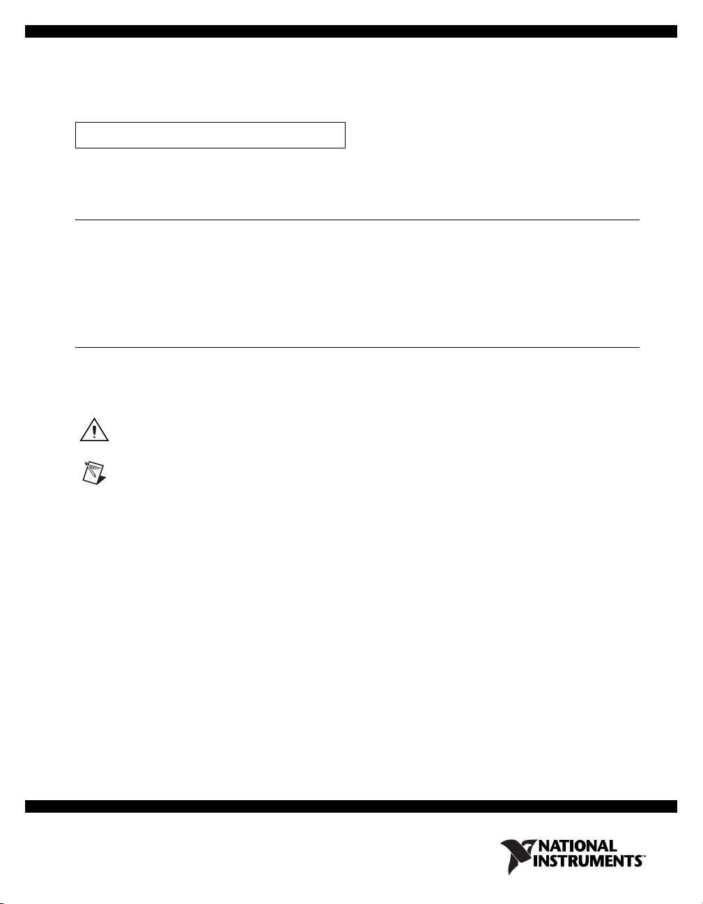
The following figure shows the 160-pin cable for the NI PXI-2530B.
NATIONAL
INSTRUMENTS
NATIONAL
INSTRUMENTS
NATIONAL
INSTRUMENTS
NATIONAL
INSTRUMENTS
NATIONAL
INSTRUMENTS
1
4
2
3
60VDC/30VRMS CAT I ONLY60VDC/30VRMS CAT I ONLY
NATIONAL INSTRUMENTS
P1
P2
P3
P4
1 160-Pin Cable for the NI PXI-2530B Backshell
2 Cable Leg Labels
Figure 1. 160-Pin Cable for the NI PXI-2530B
What You Need to Get Started
3 50-Pin Female D-SUB Connector Backshells
4Thumbscrews
To use the cable, you need the following items:
❑ 160-pin cable for the NI PXI-2530B
❑ (Optional) Four NI TBX-50 screw terminal blocks
❑ NI PXI-2530B switch module and documentation
160-Pin Cable for the NI PXI-2530B Installation Instructions 2 ni.com
❑ #1 Phillips screwdriver
Page 3
Getting Started with the 160-Pin Cable for the NI PXI-2530B
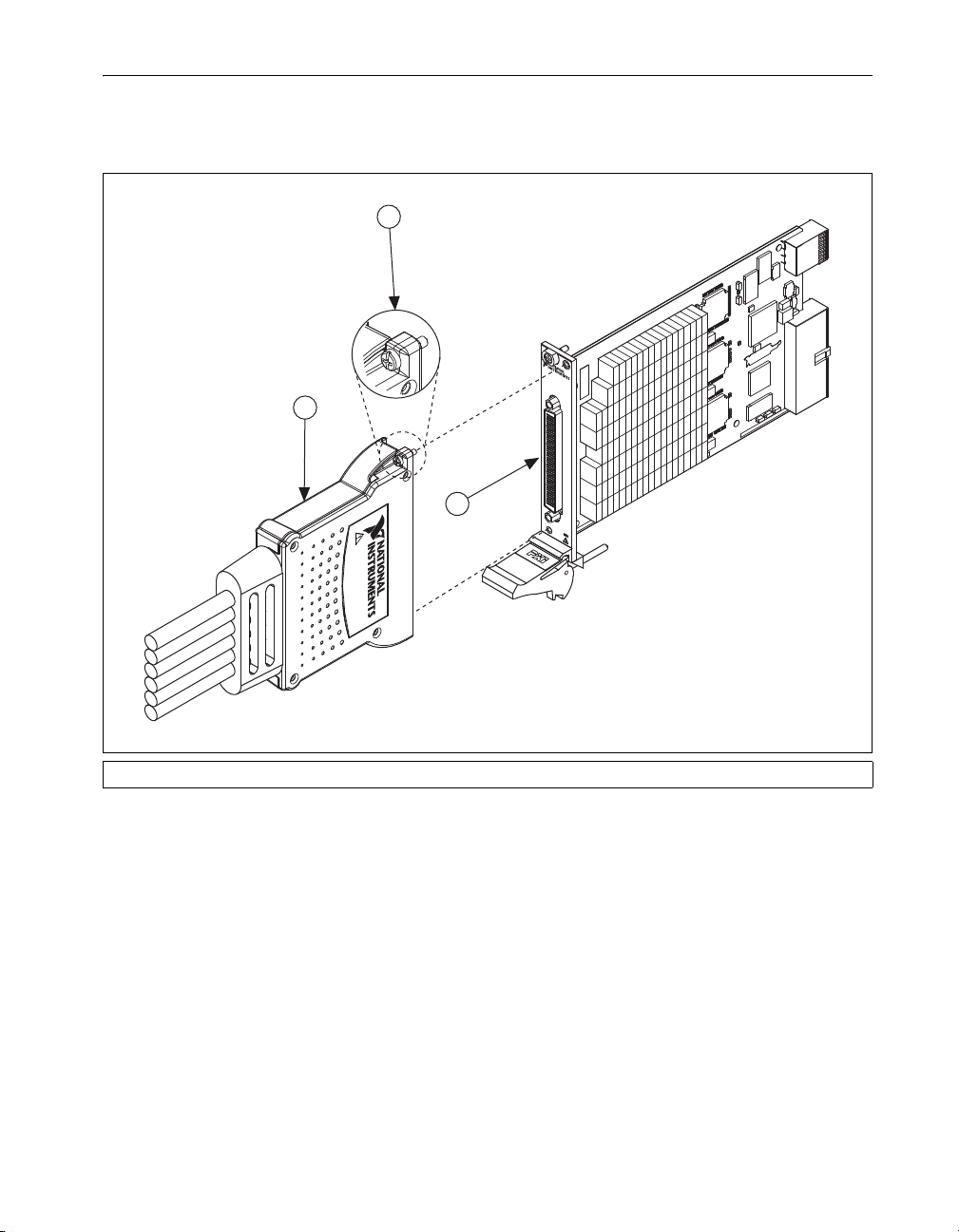
Complete the following steps to connect the cable to the NI PXI-2530B and your application.
1. Connect the cable backshell to the NI PXI-2530B connector on the switch module as shown in
Figure 2.
2
NI PXI-2530B
128-Channel
Reed Relay
Multiplexer / Matrix
1
3
60VDC/30VRMS CAT I ONLY
1 Backshell 2 Chassis Screws 3 NI PXI-2530B Connector
Figure 2. Connecting the Cable to the NI PXI-2530B
2. Tighten the chassis screws on the cable.
3. Connect the D-SUB connectors on the cable to your application. Refer to Tables 1 through 4 in the
Cable Configuration section to determine how to connect signals to your application. For screw
terminal access, you can connect directly to NI TBX-50 terminal blocks.
© National Instruments Corporation 3 160-Pin Cable for the NI PXI-2530B Installation Instructions
Page 4
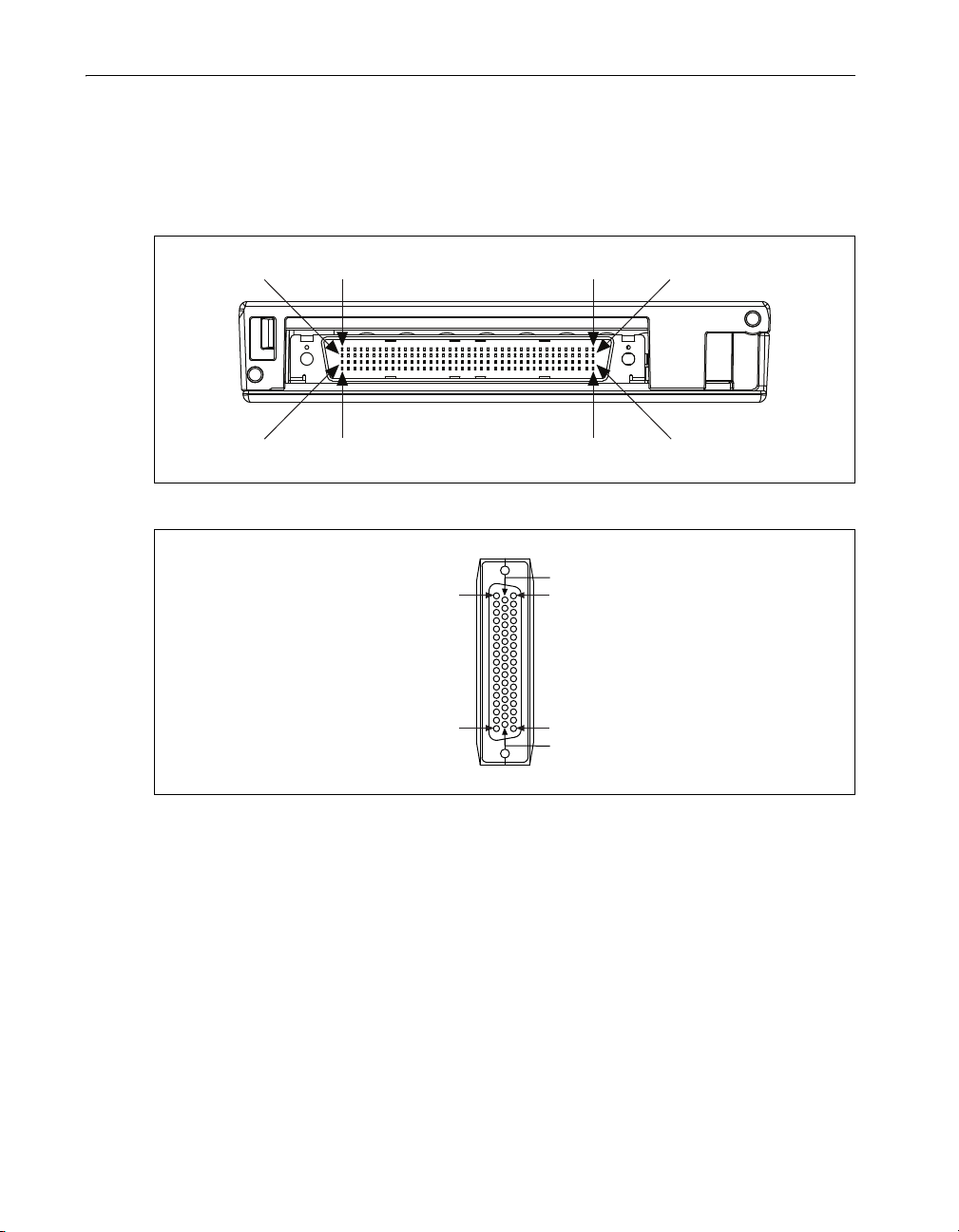
Cable Configuration
Pin 41Pin 40Pin 1Pin 80
Pin 120Pin 121Pin 160Pin 81
Pin 1
Pin 17
Pin 34
Pin 50
Pin 18
Pin 33
The cable backshell and the four 50-pin female D-SUB connectors provide connection to the
NI PXI-2530B and your application, respectively. Figures 3 and 4 show the pinouts for both connectors.
Use the pinouts and the pin assignments listed in Tables 1 through 4 to determine how to connect signals
to your application.
Refer to the NI Switches Help for a complete listing of channel names and pinouts.
Figure 3. NI PXI-2530B Mating Connector
Figure 4. 50-Pin Female D-SUB Connector
160-Pin Cable for the NI PXI-2530B Installation Instructions 4 ni.com
Page 5

Table 1. Pin Assignments for D-SUB Backshell P1
50-Pin D-SUB Backshell P1
D-SUB Pin NI PXI-2530B Channel Interface Connector Pin
1 CH64 120
2 CH65 121
3 CH66 119
4 CH67 122
5 CH68 118
6 CH69 123
7 CH70 117
8 CH71 124
9 CH72 116
10 CH73 125
11 CH74 115
12 CH75 126
13 CH76 114
14 CH77 127
15 CH78 113
16 CH79 128
17 CH80 111
18 CH81 130
19 CH82 112
20 CH83 129
21 CH84 109
22 CH85 132
23 CH86 108
24 CH87 133
25 CH88 107
26 CH89 134
27 CH90 106
28 CH91 135
29 CH92 105
30 CH93 136
© National Instruments Corporation 5 160-Pin Cable for the NI PXI-2530B Installation Instructions
Page 6

Table 1. Pin Assignments for D-SUB Backshell P1 (Continued)
50-Pin D-SUB Backshell P1
D-SUB Pin NI PXI-2530B Channel Interface Connector Pin
31 CH94 104
32 CH95 137
33 OUT4 110
34 OUT5 131
35 1WREF2 103
36 No Connect —
37 No Connect —
38 No Connect —
39 No Connect —
40 No Connect —
41 No Connect —
42 No Connect —
43 No Connect —
44 No Connect —
45 No Connect —
46 No Connect —
47 No Connect —
48 No Connect —
49 No Connect —
50 No Connect —
P1 Shell GND Shell
160-Pin Cable for the NI PXI-2530B Installation Instructions 6 ni.com
Page 7

Table 2. Pin Assignments for D-SUB Backshell P2
50-Pin D-SUB Backshell P2
D-SUB Pin NI PXI-2530B Channel Interface Connector Pin
1 CH0 41
2 CH1 40
3 CH2 42
4 CH3 39
5 CH4 43
6 CH5 38
7 CH6 44
8 CH7 37
9 CH8 45
10 CH9 36
11 CH10 46
12 CH11 35
13 CH12 47
14 CH13 34
15 CH14 48
16 CH15 33
17 CH16 50
18 CH17 31
19 CH18 49
20 CH19 32
21 CH20 52
22 CH21 29
23 CH22 53
24 CH23 28
25 CH24 54
26 CH25 27
27 CH26 55
28 CH27 26
29 CH28 56
30 CH29 25
© National Instruments Corporation 7 160-Pin Cable for the NI PXI-2530B Installation Instructions
Page 8

Table 2. Pin Assignments for D-SUB Backshell P2 (Continued)
50-Pin D-SUB Backshell P2
D-SUB Pin NI PXI-2530B Channel Interface Connector Pin
31 CH30 57
32 CH31 24
33 OUT0 51
34 OUT1 30
35 1WREF0 58
36 No Connect —
37 No Connect —
38 No Connect —
39 No Connect —
40 No Connect —
41 No Connect —
42 No Connect —
43 No Connect —
44 No Connect —
45 No Connect —
46 No Connect —
47 No Connect —
48 No Connect —
49 No Connect —
50 No Connect —
P2 Shell GND Shell
160-Pin Cable for the NI PXI-2530B Installation Instructions 8 ni.com
Page 9

Table 3. Pin Assignments for D-SUB Backshell P3
50-Pin D-SUB Backshell P3
D-SUB Pin NI PXI-2530B Channel Interface Connector Pin
1 CH32 67
2 CH33 15
3 CH34 12
4 CH35 11
5 CH36 70
6 CH37 61
7 CH38 20
8 CH39 62
9 CH40 19
10 CH41 63
11 CH42 18
12 CH43 64
13 CH44 17
14 CH45 65
15 CH46 16
16 CH47 66
17 CH48 14
18 CH49 68
19 CH50 13
20 CH51 69
21 CH52 1
22 CH53 4
23 CH54 3
24 CH55 71
25 CH56 10
26 CH57 72
27 CH58 9
28 CH59 73
29 CH60 8
30 CH61 74
© National Instruments Corporation 9 160-Pin Cable for the NI PXI-2530B Installation Instructions
Page 10

Table 3. Pin Assignments for D-SUB Backshell P3 (Continued)
50-Pin D-SUB Backshell P3
D-SUB Pin NI PXI-2530B Channel Interface Connector Pin
31 CH62 7
32 CH63 75
33 OUT2 5
34 OUT3 76
35 1WREF1 6
36 No Connect —
37 No Connect —
38 No Connect —
39 No Connect —
40 No Connect —
41 No Connect —
42 No Connect —
43 No Connect —
44 No Connect —
45 No Connect —
46 No Connect —
47 No Connect —
48 No Connect —
49 No Connect —
50 No Connect —
P3 Shell GND Shell
160-Pin Cable for the NI PXI-2530B Installation Instructions 10 ni.com
Page 11

Table 4. Pin Assignments for D-SUB Backshell P4
50-Pin D-SUB Backshell P4
D-SUB Pin NI PXI-2530B Channel Interface Connector Pin
1 CH96 94
2 CH97 149
3 CH98 91
4 CH99 150
5 CH100 146
6 CH101 100
7 CH102 141
8 CH103 99
9 CH104 142
10 CH105 98
11 CH106 143
12 CH107 97
13 CH108 144
14 CH109 96
15 CH110 145
16 CH111 95
17 CH112 147
18 CH113 93
19 CH114 148
20 CH115 92
21 CH116 85
22 CH117 81
23 CH118 157
24 CH119 90
25 CH120 151
26 CH121 89
27 CH122 152
28 CH123 88
29 CH124 153
30 CH125 87
© National Instruments Corporation 11 160-Pin Cable for the NI PXI-2530B Installation Instructions
Page 12

Table 4. Pin Assignments for D-SUB Backshell P4 (Continued)
50-Pin D-SUB Backshell P4
D-SUB Pin NI PXI-2530B Channel Interface Connector Pin
31 CH126 154
32 CH127 86
33 OUT6 156
34 OUT7 84
35 1WREF3 155
36 DGND 83
37 DGND 158
38 TRIGIN 159
39 TRIGOUT 82
40 No Connect —
41 No Connect —
42 No Connect —
43 No Connect —
44 No Connect —
45 No Connect —
46 No Connect —
47 No Connect —
48 No Connect —
49 No Connect —
50 No Connect —
P4 Shell GND Shell
160-Pin Cable for the NI PXI-2530B Installation Instructions 12 ni.com
Page 13

Specifications
Maximum voltage ..................................................60 VDC/30 VRMS, CAT I
Maximum current .................................................. 0.4 A
Caution Do not connect to MAINs supply circuits (e.g., wall outlets) of 115 or 230 VAC. Refer to
the Read Me First: Safety and Electromagnetic Compatibility document at ni.com/manuals for
more information about Measurement Categories.
Weight ....................................................................1206.6 g (42.6 oz)
Environment
Operating temperature ...........................................0 °C to 55 °C
Storage temperature ...............................................–20 °C to 70 °C
Relative humidity...................................................5% to 85%, noncondensing
Pollution Degree ....................................................2
Maximum altitude..................................................2,000 m
Indoor use only.
Safety
This product meets the requirements of the following standards of safety for electrical equipment for
measurement, control, and laboratory use:
• IEC 61010-1, EN 61010-1
• UL 61010-1, CSA 61010-1
© National Instruments Corporation 13 160-Pin Cable for the NI PXI-2530B Installation Instructions
Page 14

Accessories
Vis it ni.com for information about the following accessory.
Caution Do not use unshielded cables or accessories unless they are installed in a shielded enclosure
with properly designed and shielded input/output ports, and are connected to the NI product using a
shielded cable. If unshielded cables or accessories are not properly installed and shielded, the EMC
specifications for the product are no longer guaranteed.
Table 5. NI Accessory for the 160-Pin Cable for the NI PXI-2530B
Accessory Part Number
NI TBX-50 unshielded terminal block, with screw connection and
779305-01
50 position D-Subminiature pin strip
Caution You must install mating connectors according to local safety codes and standards and
according to the specifications provided by the connector manufacturer. You are responsible for
verifying safety compliance of third-party connectors and their usage according to the relevant
standard(s), including UL and CSA in North America and IEC and VDE in Europe.
Refer to Table 6 for information about third-party accessories.
Table 6. Third-Party Accessories for the 160-Pin Cable for the NI PXI-2530B
Accessory Manufacturer Part Number
VARIOFACE module, with screw connection and
Phoenix Contact FLKM-D50 SUB/S
50 position D-Subminiature pin strip
VARIOFACE module, with screw connection and
Phoenix Contact FLKMS-D50 SUB/S
50 position D-Subminiature pin strip
VARIOFACE module, with screw connection and
Phoenix Contact FLKM-D50 SUB/S/LA
50 position D-Subminiature pin strip, with
LED indicators
Right-angle 50 position male D-SUB connector
*
Small quantity orders are available from Digi-Key Corporation (part number A23398-ND).
*
Tyc o 747497-4
LabVIEW, National Instruments, NI, ni.com, the National Instruments corporate logo, and the Eagle logo are trademarks of National Instruments
Corporation. Refer to the Trademark Information at ni.com/trademarks for other National Instruments trademarks. Other product and
company names mentioned herein are trademarks or trade names of their respective companies. For patents covering National Instruments
products/technology, refer to the appropriate location: Help»Patents in your software, the patents.txt file on your media, or the National
Instruments Patent Notice at ni.com/patents. Refer to the Export Compliance Information at ni.com/legal/export-compliance for
the National Instruments global trade compliance policy and how to obtain relevant HTS codes, ECCNs, and other import/export data.
© 2010–2011 National Instruments Corporation. All rights reserved.
375656B Apr11
 Loading...