

Page 1
Getting Started with Your PXI
Unpack your PXI-1002 chassis and documentation.
1
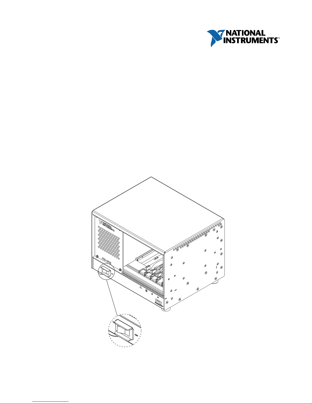
Power off the chassis.
2
™
-1002
Power Switch
Page 2
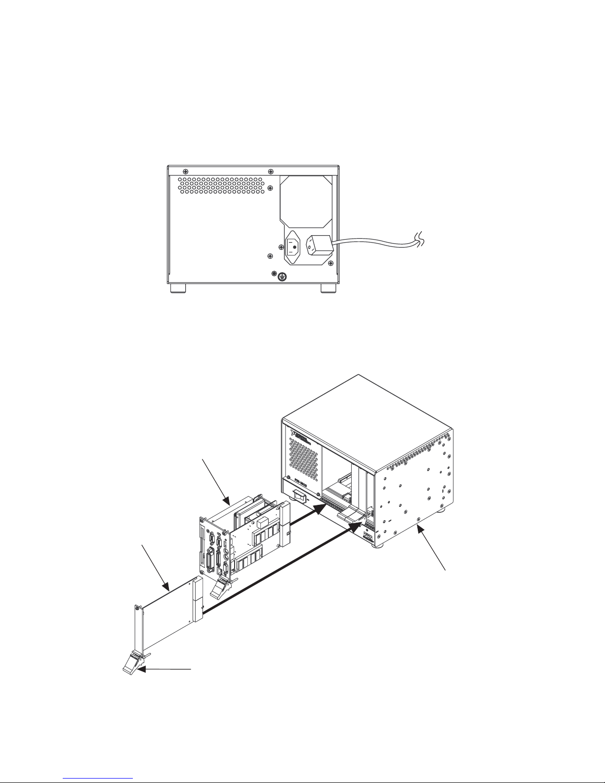
Plug in the AC power cord.
3
4
(Power cords are available from National Instruments, or use a power cord that
meets the requirements of ANSI/UL817 for use in the United States, CSA C22.2 21
and 49 for use in Canada, and IEC 227 or 245 for use in the European Union.
AC mains power supply cords used with the PXI-1002 in other countries must be
approved by the authority having jurisdiction in that country.)
Power Cord
Install your controller in Slot 1 of your PXI-1002.
Install peripheral cards, if any, in slots 2 through 4.
PXI Controller
Peripheral Card
Ejector Handle in Down Position
Power on the chassis.
PXI-1002 Chassis
5
Page 3
Maintenance
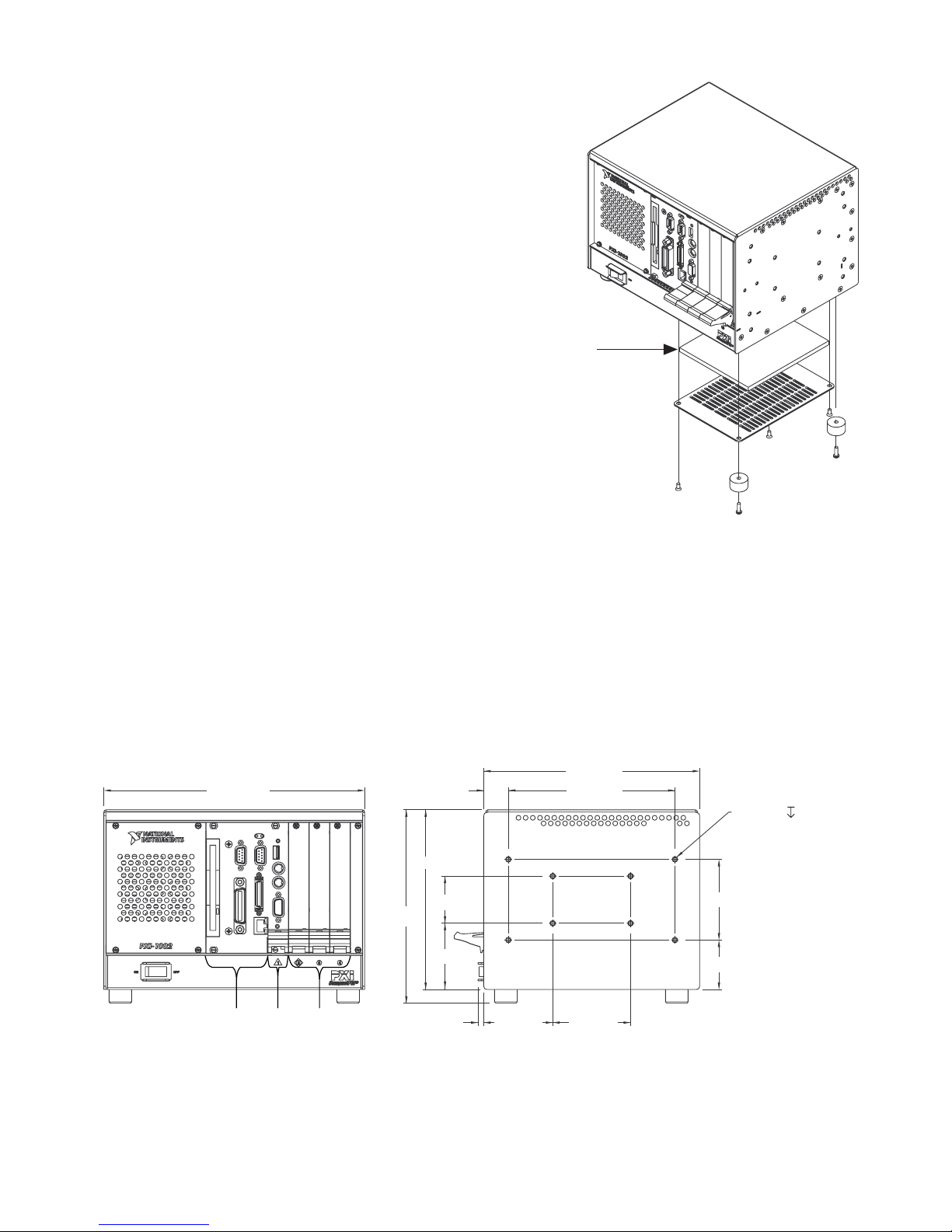
To clean filters, remove five screws, two
rubber feet, and panel as shown. Remove
filter and clean by washing it in a mild soap
solution and rinse. Allow to dry before
reinstalling filter, panel, feet, and screws.
Filter
Dimensions and Mounting Holes
Below are the PXI-1002 dimensions and mounting holes for the optional rack
mount kit (available from National Instruments).
Note: To facilitate power supply and module cooling, place the PXI-1002 on a
bench top or instrument rack so that other equipment is kept a minimum of
3.0 in. (76.2 mm) from air inlets and outlets.
8.38 in.
10.12 in.
Three
controller
expansion
slots
System
slot
7.50 in.
Three
peripheral
slots
0.96 in.
6.97 in.
1.83 in.
2.57 in.
0.22 in.
2.68 in.
6.46 in.
8X M4, .25 Max
both sides of
chassis for
mounting purposes
3.13 in.
1.92 in.
3.02 in.
Page 4
For Your Safety
!
This equipment contains voltage hazardous to human life and safety, and is capable of inflicting personal injury.
•
•
•
•
Caution
WARNING and CAUTION notices.
Mainframe Grounding
chassis ground. The earth safety ground must be connected during use of this equipment to minimize shock hazards.
Live Circuits
servicing the PXI-1002.
Explosive Atmosphere
conditions this equipment is unsafe and may ignite the gases or gas fumes.
Modification
result in safety hazards.
Before undertaking any troubleshooting, maintenance, or exploratory procedure, read carefully the
—The PXI-1002 requires a connection from the premise wire safety ground to the PXI-1002
—Operating personnel and service personnel must not remove protective covers when operating or
—Do
—Do
modify any part of the mainframe from its original condition. Unsuitable modifications may
not
operate the mainframe in conditions where flammable gases are present. Under such
not
Connecting Safety Ground
Warning
ground line to the chassis ground. To minimize shock hazard, make sure your electrical power outlet has an
appropriate earth safety ground that is connected whenever you power up the chassis.
If your power outlet does
the chassis grounding screw located on the rear panel. To connect the safety ground, complete the following steps:
1. Connect a 16 AWG (1.3 mm) wire to the chassis grounding screw on the rear of the chassis using a toothed grounding
lug. The wire must have green insulation with a yellow stripe or must be noninsulated (bare).
2. Attach the opposite end of the wire to permanent earth ground using toothed washers or a toothed lug.
The PXI-1002 chassis is designed with a three-position NEMA 15-5 style plug that connects the
have an appropriate ground connection, you must connect the premise wire safety ground to
not
Specifications
AC Input Specifications for AC-Only
Power Supply
Input voltage range.........90–135/180–265 VAC
auto select
Input frequency range ...47 to 63 Hz
Input current......................8 A @ 115 VAC; 5 A @ 230 VAC
Power disconnect.............The power switch causes the power
module to supply DC power to the
PXI-1002 backplane. The power cord
provides main power disconnect.
Note
There are no user-replaceable fuses.
Safety
UL 3111-1, IEC 1010-1, CSA 22.2 No. 1010.1; Installation
Category II; Pollution Degree 2; Safety Class 1
Backplane
Backplane bare-board material: UL 94 V-0 recognized (File No. E 96467); Backplane connectors: Conform to IEC 917 and IEC
1076-4-101, and are UL 94 V-0 rated
DC Output Specifications for AC-Only
Power Supply
Maximum power..............................170 W
DC Current Capacity (IMP)
Vol ta ge IMP (Steady-State Current)
+3.3 V* 14 A
+5 V* 20 A
+12 V 4 A
–12 V 0.8 A
*Total combined power from +3.3 V and +5 V is 112 W max.
Environmental
For indoor use only.
Operating temperature.................0 to 50 °C ambient
Storage temperature......................–40 to +70 °C
Operating relative humidity ........10 to 90%, noncondensing
PXI™ is a trademark of National Instruments Corporation. Product and company names
mentioned herein are trademarks or trade names of their respective companies.
© Copyright 2000 National Instruments Corporation. All rights reserved.
National Instruments Corporate Headquarters: 11500 North Mopac Expressway,
Austin, TX 78759-3504 USA Tel: 512-794-0100
 Loading...