

Page 1

PXI
PXI™-1000 User Manual
PXI-1000 User Manual
January 1998 Edition
Part Number 321710B-01
Page 2

Internet Support
E-mail: support@natinst.com
FTP Site: ftp.natinst.com
Web Address: http://www.natinst.com
Bulletin Board Support
BBS United States: 51 2 794 5422
BBS United Kingd om: 01635 551422
BBS France: 01 48 65 15 59
Fax-on-Demand Support
512 418 1111
Telephone Support (USA)
Tel: 512 795 8248
Fax: 512 794 5678
International Offices
Australia 03 9879 5166, Austria 0662 45 79 90 0, Belgium 02 7 57 00 20, Brazil 011 288 3336,
Canada (Ontario) 905 785 0085, Canada (Québec) 514 694 8521, Denmark 45 76 26 00, Finland 09 725 725 11,
France 01 48 14 24 24, Germany 089 741 31 30, Hong Kong 2645 3186, Israel 03 6120092, Italy 02 413091,
Japan 03 5472 2970, Kore a 02 596 7456, Mexico 5 520 2635, Netherlands 0348 433466, Norway 32 84 84 00,
Singapore 2265886, Spain 91 640 0085, Sweden 08 730 49 70, Switzerland 056 200 51 51, Taiwan 02 377 1200,
United Kingdom 01635 523545
National Instruments Corporate Headquarters
6504 Bridge Point Parkway Austin, Texas 78730 -5039 USA Tel: 512 794 0100
© Copyright 1997, 1998 National Instruments Corporation. All rights reserved.
Page 3

Important Information
Warranty
The PXI-1000 is warranted against defects in materials and workmanship for a period of one year from the date of
shipment, as evidenced by receipts or other documentation. National Instruments will, at its option, repair or replace
equipment that proves to be defective during the warranty period. This warranty includes parts and labor.
The media on which you receive National Instruments software are warranted not to fail to execute programming
instructions, due to defects in materials and workmanship, for a period of 90 days from date of shipment, as evidenced
by receipts or other documentation. National Instruments will, at its option, repair or replace software media that do not
execute programming instructions if National Instruments receives notice of such defects during the warranty period.
National Instruments does not warrant that the operation of the software shall be uninterrupted or error free.
A Return Material Authorization (RMA) number must be obtained from the factory and clearly marked on the outside
of the package before any equipment will be accept ed for warranty work. National Instru ments will pay the shippi ng costs
of returning to the owner parts which are covered by warranty.
National Instruments believes that the informatio n in this manual is accurate. The docume nt has been ca refully review ed
for technical accurac y. In th e even t that te ch nical o r typograp hic al errors exis t, Nation al Inst ruments rese rves th e right to
make changes to subsequent editions of this document without prior notice to holders of this edition. The reader should
consult National Instruments if errors are suspected. In no event shall National Instruments be liable for any damages
arising out of or related to this document or the information contained in it.
XCEPT AS SPECIFIED HEREIN
E
ANY WARRANTY OF MERCHANTABILITY OR FITNESS FOR A PARTICULAR PURPOSE
BY FAULT OR NEGLIGENCE ON THE PART OF NATIONAL INSTRUMENTS SHALL BE LIMITED TO THE AMOUNT THERETOFORE PAID BY THE
CUSTOME R
OR INCIDENTAL OR CONSEQUENTIAL DAMAGES, EVEN IF ADVISED OF THE POSSIBILITY THEREOF
National Instruments will apply regardless of the form of action, whether in contract or tort, including negligence.
Any action against National Instruments must be brought within one year after the cause of action accrues. National
Instruments shall not be liable for any delay in performance due to causes beyond its reasonable control. The warranty
provided herein does not cover damages, defects, malfunctions, or service failures caused by owner’s failure to follow
the National Instruments installation, operation, or maintenance instructions; owner’s modification of the product;
owner’s abuse, misuse, or negligent acts; and power failure or surges, fire, flood, accident, actions of third parties,
or other events outside reasonable control.
ATIONAL INSTRUMENTS WILL NOT BE LIABLE FOR DAMAGES RESULTING FROM LOSS OF DATA, PROFITS, USE OF PRODUCTS
. N
ATIONAL INSTRUMENTS MAKES NO WARRANTIES, EXPRESS OR IMPLIED, AND SPECIFICALLY DISCLAIMS
, N
Copyright
Under the copyright laws, this publication may not be reproduced or transmitted in any form, electronic or mechanical,
including photocopyi ng, recordi ng, st oring in an info rmation ret riev al syste m, or translating , in whole or in part, wit hout
the prior written consent of National Instruments Corporation.
USTOMER’S RIGHT TO RECOVER DAMAGES CAUSED
. C
. This limitation of the liability of
,
Trademarks
PXI™ is a trademark of National Instruments Corporation.
Product and company names listed are trademarks or trade names of their respective companies.
WARNING REGARDING MEDICAL AND CLINICAL USE OF NATIONAL INSTRUMENTS PRODUCTS
National Instruments products are not designed with components and testing intended to ensure a level of reliability
suitable for use in treatment and diagnosis of humans. Applications of National Instruments products involving medical
or clinical treatment can create a potential for accidental injury caused by product failure, or by errors on the part of the
user or application des igner. Any us e or ap plica tion of Na tiona l Instrum ents pr oducts for or inv olving m edi cal or clin ica l
treatment must be performed by properly trai ned and qualifi ed medic al pe rsonne l, and al l tra ditiona l medic al safegu ards,
equipment, and procedu res that are appropriate in the particula r situation to prevent serious injury or dea th should al ways
continue to be used when Natio nal Instrume nts products are being use d. National In struments prod ucts are N OT intended
to be a substitute for any form of establis hed process, procedure, or e quipment us ed to monit or or safeguard human heal th
and safety in medical or clinical treatment.
Page 4

Compliance
FCC/DOC Radio Frequency Interference
Class A Compliance
This equipment generates and uses radio frequency energy and, if not installed and used in strict accordance
with the instructions in this manual, may cause interference to radio and television reception. Classification
requirements are the same for the Federal Communications Commission (FCC) and the Canadian
Department of Communi cations (DOC). This equipment has been tested and found to comply with the
following two regulatory agencies :
Federal Communications Commission
This equipment has bee n tested and found to compl y wi th t h e l im i ts for a Cla s s A digital device, pursua nt
to part 15 of the FCC Rules. These limits are de signed to provide reasonable protection agai nst ha rm ful
interference when the equipment is operate d in a commercial environment. This equipm ent generates,
uses, and can radiate radio frequency energy and, if not installed and used in accordance with the instruction
manual, may cause harmful interference to radio communicati ons. Operation of this equi pment in a
residential area is likely to cause harmful interference in which case the use r w il l be required to correct the
interference at his own expense.
Notices to User: Changes or modifications not expressly approved by National Instruments could void
If necessary, consult Nation al Instruments or an experien ced radio/television tech nician for additional
suggestions. The following bookl et prepared by the FCC may also be hel pful: Interference to H o me
Electronic Entertainment Equipment Handb ook. This booklet is available from the U.S. Government
Printing Office, Washington , DC 20402.
the user’s authority to operate the equipment under the FCC Rules.
This device complies with the FCC rules only if used with shielded in te rfac e cables
of suitable quality and construction. National Instruments used such cables to test
this device and provides them for sale to the user. The use of inferior or nonshielded
interface cabl es co ul d void the user’s authority to operate the equ ip men t under the
FCC rules.
Canadian Department of Communications
This Class A digital appar at us meets all requirements of th e Canadian Interference -Causing Equipment
Regulations.
Cet appareil numérique de la classe A respecte toutes les exigences du Règlement sur le matériel brouilleur
du Canada.
Page 5

For Your Safety
Caution
!
Before undertak ing any troublesh ooting, mainten ance, or explorat ory procedure,
read carefully the WARNING and CAUTION notices.
This equipment contains voltage hazardous to human life an d safety , and is
capable of inflicting personal injury.
• Mainframe Grounding— The PXI-1000 mainframe requires a
connection from the premise wire safety ground to the PXI-1000
chassis ground. Th e earth saf ety groun d must be co nnected du ring us e
of this equipment to minimize shock hazards. Refer to the Connecting
Safety Ground section of Chapter 2, Installation and Configuratio n,
for instructions on connecting safety ground.
• Live Circuits—Operating personnel and service personnel must not
remove protective covers when operating or servicing the PXI-1000.
Adjustments and service to internal components must be undertaken
by qualified service technicians. During service of this product, the
mains connector to the premise wiring must be disconnected.
Dangerous voltages may be present under certain conditions; use
extreme caution.
• Explosive Atmosphere—Do not operate the mainframe in conditions
where flammable gases are present. Under such conditions this
equipment is unsafe and may ignite the gases or gas fumes.
• Part Replacement—Only service this equipment with parts that are
exact replacements, both electrically and mechanically. Contact
National Instruments for replacement part information. Installation of
parts with those that are not direct replacements may cause harm to
personnel operating the mainframe. Furthermore, dam age or fire may
occur if replacement parts are unsuitable.
• Modification—Do not modify any part of the mainframe from its
original condition. Unsuitable modifications may result in safety
hazards.
Page 6

Contents
About This Manual
Organization of This Manual................................................ ...... ...................................xi
Conventions Used in This Manual.................................................................................xi
Related Documentation..................................................................................................xii
Customer Communication.............................................................................................xii
Chapter 1
Getting Started
Unpacking......................................................................................................................1-1
What You Need to Get Started......................................................................................1-1
Optional Equipment.......................................................................................................1-2
Key Features..................................................................................................................1-2
PXI-1000 Backplane Overview.....................................................................................1-3
Interoperability with CompactPCI ..................................................................1-3
System Controller Slot ....................................................................................1-5
Star Trigger Slot..............................................................................................1-5
Peripheral Slots................................................................................................1-5
Local Bus.........................................................................................................1-6
Trigger Bus......................................................................................................1-6
System Reference Clock..................................................................................1-7
Chapter 2
Installation and Configuration
Site Considerations........................................................................................................2-1
Rack Mounting ..............................................................................................................2-2
Setting Fan Speed ..........................................................................................................2-2
Connecting Safety Ground.............................................................................................2-3
Connecting to AC Mains Power and Testing Power up................................................2-3
Remote Power Monitoring and Inhibiting Interface......................................................2-5
Installing PXI Modules..................................................................................................2-6
Installing Filler Panels ...................................................................................................2-7
Using the Chassis Initialization File..............................................................................2-7
Chapter 3
Maintenance
Service Interval..............................................................................................................3-1
Preparation.....................................................................................................................3-1
©
National Instruments Corporation vii PXI-1000 User Manual
Page 7

Contents
Cleaning.........................................................................................................................3-1
Interior Cleaning.............................................................................................3-2
Exterior Cleaning............................................................................................3-2
Cleaning the Fan Filters.................................................................................................3-2
Resetting the AC Mains Circuit Breaker.......................................................................3-3
Troubleshooting the PXI-1000......................................................................................3-4
Appendix A
Specifications
Appendix B
Pinouts
Appendix C
Customer Communication
Glossary
Index
Figures
Figure 1-1. Front View of the PXI-1000 Mainframe .............................................. 1-4
Figure 1-2. Rear View of the PXI-1000 Mainframe................................................1-5
Figure 1-3. PXI Local Bus and Star Trigger Routing..............................................1-6
Figure 2-1. PXI-1000 Mainframe Airflow Side View.............................................2-2
Figure 2-2. Installing PXI or CompactPCI Modules............................................... 2-6
Figure 2-3. Injector/Ejector Handle Position during Module Insertion...................2-7
Figure A-1. PXI-1000 Dimensions........................................................................... A-7
Tables
Table 1-1. Power Cables ........................................................................................1-1
Table 2-1. Power Supply Voltages at Power Monitoring Connector (DB-9) ........2-4
Table 2-2. DB-9 Connector Pinout.........................................................................2-5
Table 3-1. Troubleshooting....................................................................................3-4
PXI-1000 User Manual viii
©
National Instruments Corporation
Page 8

Contents
Table A-1. AC Input Specifications ........................................................................A-1
Table A-2. DC Output Specifications......................................................................A-2
Table A-3. Cooling Specifications ..........................................................................A-3
Table A-4. Safety Specifications.............................................................................A-3
Table A-5. Environmental Specifications................................................................A-4
Table A-6. Backplane Specifications ......................................................................A-5
Table A-7. Mechanical Specifications.....................................................................A-6
Table B-1. P1 (J1) Connector Pinout for the System Controller Slot.....................B-2
Table B-2. P2 (J2) Connector Pinout for the System Controller Slot.....................B-3
Table B-3. P1 (J1) Connector Pinout for the Star Trigger Slot...............................B-4
Table B-4. P2 (J2) Connector Pinout for the Star Trigger Slot...............................B-5
Table B-5. P1 (J1) Connector Pinout for the Peripheral Slot..................................B-6
Table B-6. P2 (J2) Connector Pinout for the Peripheral Slot..................................B-7
©
National Instruments Corporation ix PXI-1000 User Manual
Page 9

About This Manual
The PXI-1000 User Manual describes the features of the PXI-1000
mainframe and contains information about configuring the mainframe,
installing the modules, and operating and using the PXI-1000.
Organization of This Manual
This manual is organized as follows:
• Chapter 1, Getting Started, describes the key features of t he PXI-1000,
lists the contents of your kit, and lists optional equipment you can
order from N ational Instruments.
• Chapter 2, Installation and Configuration, describes how to prepare
and operate your PXI-1000 mainframe.
• Chapter 3, Maintenance, describes basic maintenance pro cedures you
can perform on the PXI-1000 mainframe.
•AppendixA, Specifications, contains complete specifications for the
PXI-1000 mainframe.
•AppendixB, Pinouts, describes the P1 and P2 connector pinouts for
the PXI-1000 backplane.
•AppendixC, Customer Communication, contains forms you can use to
request help from Nati onal Instruments o r to comment on our products
and manuals.
•The Glossary lists abbreviations, acronyms, metric prefixes,
mnemonics, symbols, and terms.
•The Index contains an alphabetical list of key terms and topics used in
this manual, including the page where you can find each one.
Conventions Used in This Manual
The following conventions are used in this manual:
This icon to the left of bold italicized text denotes a note, which alerts you
to important information.
!
©
National Instruments Corporation xi PXI-1000 User Manual
This icon to the left of bold italicized text denotes a caution, which advises
you of precautions to take to avoid injury, data loss, or a system crash.
Page 10

About This Manual
This icon to the left of bol d italicized te xt denotes a warni ng, which advises
you of precautions to take to avoid being electrically shocked.
bold italic Bold italic text denotes a note, caution, or warning.
italic Italic text denotes emphasis, a cross reference, or an introduction to a key
concept. This font also den otes text from whi ch you supply t he appropriate
word or value, as in Windows 3.x.
monospace T ext in this font denotes text or characters that are to be literally enter from
the keyboard, sections of code, programming examples, and syntax
examples. This font is also used for the proper n ames of disk d ri ves, p aths,
directories, device names, functions, variables, filenames, and extensions.
Related Documentation
The following document s contain informat ion that you may f ind helpful as
you read this manual:
• Compact PCI Specification PICMG 2.0 R2.1
• PXI Specification Revision 1.0
• IEEE 1101.1-1991, IEEE Standard for Mechanical Cor e
Specifications for Microcomputers Using IEC 603-2 Connectors
• IEEE 1101.10 and P1101.11, IEEE Standard for Additional
Mechanical Specifications for Microcomputers Using IEEE 1101.1
Equipment Practice
Customer Communication
National Instruments wants to receive your comments on our products
and manuals. We are interested in the applications you develop with our
products, and we want to help if you have problems with them. To make it
easy for you to contact us, this manual contains comment and configuration
forms for you to complete. These forms are in Appendix C, Customer
Communication, at the end of this manual.
PXI-1000 User Manual xii
©
National Instruments Corporation
Page 11

Getting Started
This chapter describes the key features of the PXI-1000, lists the contents
of your kit, and lis ts optional equipment you can order from National
Instruments.
Unpacking
Carefully inspect the shipping container and the mainframe for damage.
Check for visible damage to the metal work. Check to make sure all
handles, hardware, and switches are undamaged. Inspect the inner chassis
for any possible damage, debris, or detached components. If damage
appears to have been caused in shipment, file a claim with the carrier.
Retain the packing material for possible inspection and/or reshipment.
What You Need to Get Started
The PXI-1000 kit contains the following items:
1
❑ PXI-1000 mainframe
❑ Filler panels
❑ Power cable (see Table 1-1)
❑ PXI-1000 User Manual
❑ Floppy disk with Chassis Initialization file, chassis.ini
Table 1-1.
Power Cable Reference Standards
Standard 120 V (USA) ANSI C73.11/NEMA 5-15-P/IEC83
Switzerland 220 V SEV
Australia 240 V AS C112
©
National Instruments Corporation 1-1 PXI-1000 User Manual
Power Cables
Page 12

Chapter 1 Getting Started
Universal Euro 240 V CEE (7), II, IV, VII IEC83
North America 240 V ANSI C73.20/N EMA 5-15-P/IE C83
United Kingdom 240 V BS 1363/IEC83
If you are missing any of t he above items or if yo u have the incorrect power
cord, contact National Instruments.
Optional Equipment
An optional rack-mount kit is available from National Instruments. You
can use this kit to install the PXI-1000 mainframe into a standard 19 in.
(482 mm) instrument cabinet. Contact National Instruments to order the
PXI-1000 rack-mount kit.
Key Features
The PXI-1000 combines a high-performance 8-slot PXI backplane with a
high-output power supply and a structural design that has been optimized
for maximum usability in a wide range of applications. The mainframe’s
modular design ensures the highest lev e l of maintainability resulting in a
very low mean time to repair (MTTR). The PXI-1000 fully complies with
the PXI Specification, Revision 1.0, offering advanced timing and
synchronization features.
Table 1-1.
Power Cable Reference Standards
Power Cables (Continued)
The key features of the PXI-1000 include:
• PXI and CompactPCI (PICMG 2.0 R 2.1) module compatibility
• Compact 3U-sized, 8-slot chassis
• 300 W of usable power
• Universal AC input: auto-voltage and auto-frequency ranging
• Over-current protection via push-reset circuit breaker (no loose fuses
to replace)
• Removable modular power supply with MTBF of 90,000 hours
• Remote power status and inhibit via a rear panel connector
• On/Off (Standby) switch located on the front panel for easy access
PXI-1000 User Manual 1-2
©
National Instruments Corporation
Page 13

• Selectable fan speed for maximum cooling or quiet operation
• Carrying handle for portability
• Tilt feet for bench-top applications
PXI-1000 Backplane Overview
Interoperability with CompactPCI
The PXI-1000 backplane is interoperable with PXI-compatible products
and standard CompactPCI products. This is an important feature, as many
PXI-compatible systems may not require components that do not
implement PXI-specific features. For example, you may want to use a
standard CompactPCI network interface card in a PXI chassis.
The signals on the P1 connector of the backplane meet the requirements of
the CompactPCI specification for both the periph eral and system mo du les.
The PXI-specific signals are located on P2 and are only found on the
signals that are reserved or not used in the CompactPCI 64-bit
specification. Therefore, all modules that meet the requirements of the
CompactPCI 64-bit specification will function in the PXI-1000.
Chapter 1 Getting Started
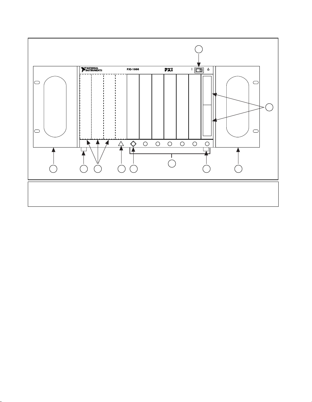
Figures 1-1 and 1-2 show some of the ke y featur es and compon ents of the
PXI-1000 mainframe. Figure1-1 shows the fr ont view of the PX I-1000 and
Figure 1-2 shows the rear view.
©
National Instruments Corporation 1-3 PXI-1000 User Manual
Page 14
Chapter 1 Getting Started
1
ON STANDBY
22
P2
1
25
P1
1
ZABCDEF
1
8765432
2
1 Remote On/Off (Standby) Switch
2 Backplane Connectors
(Located in Slots 1-8)
5
3 Optional Mounting Brackets
4 Removable Feet
5 Peripheral Slots
Figure 1-1.
Front View of the PXI-1000 Mainframe
4
33 8 7 64
6 Star Trigger Slot
7 System Controller Slot
8 Controller Expansion Slots
PXI-1000 User Manual 1-4
©
National Instruments Corporation
Page 15
Chapter 1 Getting Started
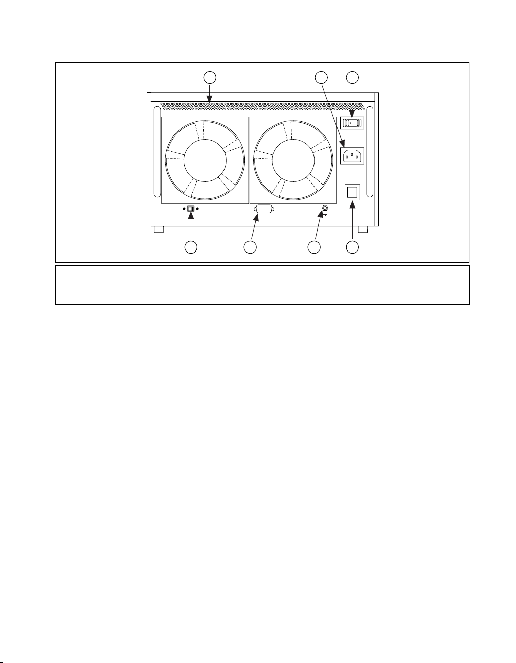
1 Module Cooling Air Outlets
2 Universal AC Input
3 Main Power Switch
4 Circuit Breaker
System Controller Slot
The System Controller slot is located in Slot 1 o f th e ch assis as def i ned by
the PXI specification. It has three controller expansion slots, which are
used for system controller modules that are wider than one slot. As defined
in the PXI specification, these slots allow the controller to expand to the left
to prevent the controller from using up peripheral slots.
1
LOHI
DB-9FAN SPEED
7
5 Chassis Ground Screw
6 Remote Power Status and
32
90-264 VAC
47-63 HZ
8A MAX
CB1
10A
DISCONNECT
POWER CORD
BEFORE REMOVING
POWER MODULE
46 5
7 Fan Speed
Selector
Inhibit Connector
Figure 1-2.
Rear View of the PXI-1000 Mainframe
Star Trigger Slot
The Star Trigger (ST) slot is located at Slot 2. This slot has a dedicated
trigger line between each peripheral slot (see Figure 1-3). This slot is
intended for modules with ST functionality that can provide individual
triggers to all other peripherals. However, if you do not require advanced
trigger functionality, you can instal l any standard peripheral module into
this slot.
Peripheral Slots
There are seven peripheral slots including the Star Trigger controller slot.
©
National Instruments Corporation 1-5 PXI-1000 User Manual
Page 16
Chapter 1 Getting Started
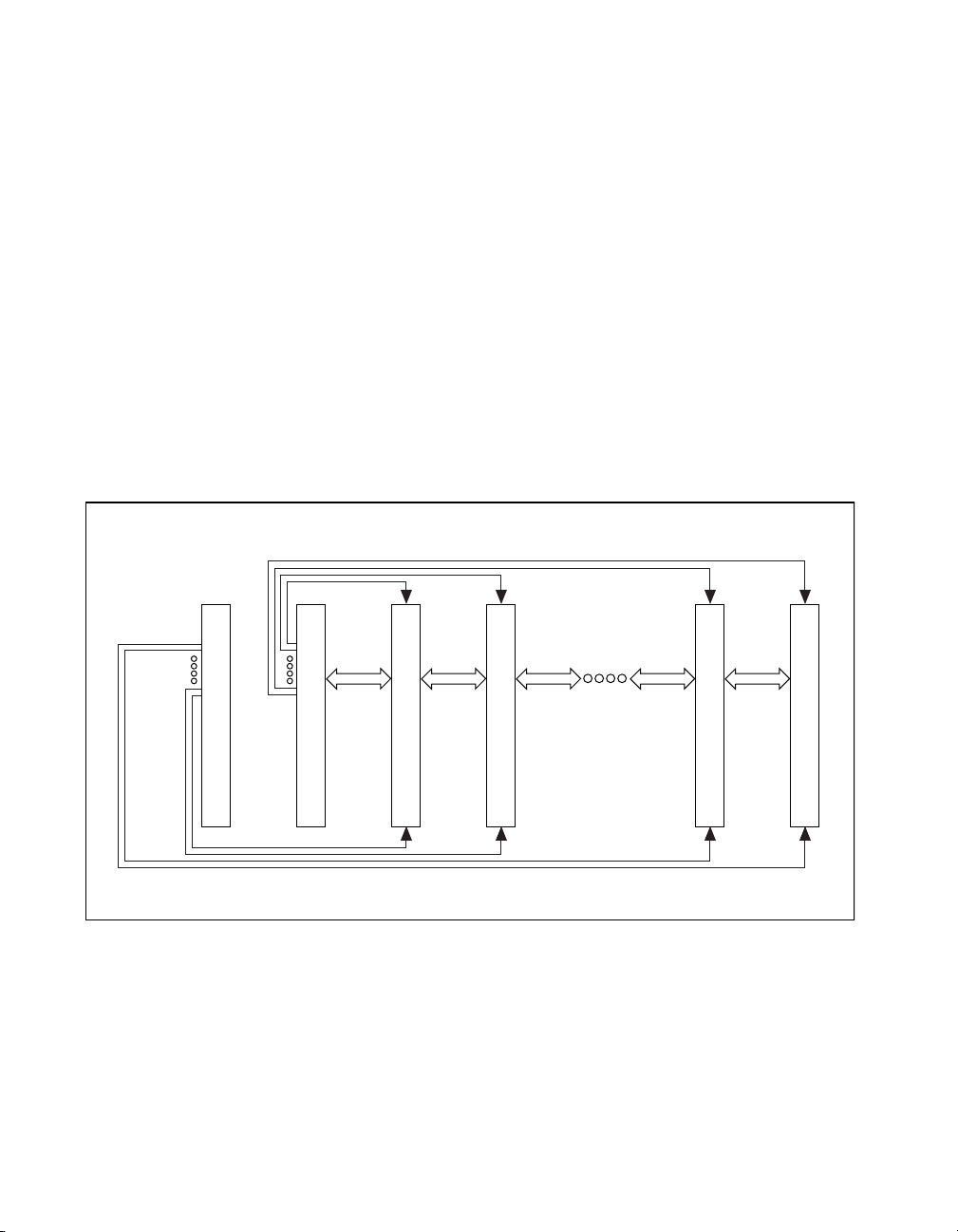
Local Bus
The PXI backplane’s local bus is a daisy-chained bus that connects each
peripheral slot with its adjacent peripheral slots to the left and right, as
shown in Figure 1-3.
For example, a given peripheral slot’s right local bus connects to the
adjacent slot’ s left local bus and so on. Each local b us is 13 lines wide an d
can pass analog signals between cards or provide a high-speed side-band
communication path that does not affect the PXI bandwidth.
Local Bus signals may range from high-speed TTL signals to analog
signals as high as 42 V. Initialization software keys adjacent boards to
prohibit the use of incompatible boards. This software uses the
configuration information specific to each peripheral board to evaluate
compatibility. This method is a flexible way to define local bus
functionality that is not limited by hardware keying.
Star Triggers
Local
Bus
System Controller Slot [1]
Star Trigger/Peripheral Slot [2]
Local
Bus
Peripheral Slot [3]
PCI Arbitration and Clock Signals
Figure 1-3.
Trigger Bus
The eight PXI trigger lines are bused to each slot. You can use the trigger
lines in a variety of ways. For exampl e, you can use t riggers to synchronize
the operation of several diff erent PXI peri pheral modules. In other
applications, one module can control carefully timed sequences of
PXI-1000 User Manual 1-6
Peripheral Slot [4]
PXI Local Bus and Star Trigger Routing
©
National Instruments Corporation
Peripheral Slot [7]
Local
Bus
Peripheral Slot [8]
Page 17

operations performed on other modules in the system. Modules can pass
triggers to one another, allowing precisely timed responses to
asynchronous external events the system is monitoring or controlling.
System Reference Clock
The PXI-1000 supplies the PXI 10 MHz system clock signal (PXI_CLK10)
independently to each peripheral slot. An independent buffer (having a
source impedance matched to the backplane and a skew of less than 1 ns
between slots) drives the clock signal to each peripheral slot. You can use
this common reference clock signal to synch r onize multiple modules in a
measurement or control system. You can drive PXI_CLK10 from an
external source through t he PXI_CLK10_IN pin on the P2 connecto r of the
Star Trigger Slot. (See Table B-1, P1 (J1) Connector Pinout for the System
Controller Slot, in Appendix B, Pinouts.) Sourcing an external clock on
this pin automatically disables the backplane’s 10 MHz source.
Chapter 1 Getting Started
©
National Instruments Corporation 1-7 PXI-1000 User Manual
Page 18

Installation and Configuration
This chapter describes how to prepare and operate your PXI-1000
mainframe.
Before connecting the mainframe to a power source, read this chapter and
the For Your Safety section located at the beginning of this manual.
Site Considerations
The PXI-1000 is designed to operate on a bench or in an instrument rack.
Determine how you want to use yo ur PXI-1000 and follow th e appropr iate
installation instructions.
Apertures in the rear and along both sides of the mainframe facilitate power
supply and module cooling. Air enters through filters and fan inlets located
in the lower rear of the mainframe and e x its thro ugh the upp er sections on
both sides and through the rear, as shown in Figure 2-1. Place your
PXI-1000 on a bench top or in an instrument rack so that the fans (air inlets)
and the air outlet apertures along both sides of the mainframe have adequate
ventilation. Keep other equipment a minimum of 3.0 in. (76.2 mm) away
from the air inlets and outlets.
2
©
National Instruments Corporation 2-1 PXI-1000 User Manual
Page 19

Chapter 2 Installation and Configuration
1
1 Module Cooling Air Outlets 2 Module Cooling Air Intake
2
Figure 2-1.
PXI-1000 Mainframe Airflow Side View
Install your mainframe so that you can easily access the rear panel. This
simplifies the replacement of the air filters or power supply/fan assembly,
if necessary.
Rack Mounting
Rack-mount applications require the optional rack-mount kit available
from National Instruments. Refer to the instructions supplied with the
rack-mount kit to install your PXI-1000 in an instrument rack.
Note You may wish to remove the feet from your PXI-1000 when rack mounting. To do
so, remove the two screws holding the feet in place.
Setting Fan Speed
The fan speed selector switch is located on the rear panel of the PXI-1000 .
Refer to Figure 1-2, Rear View of the PXI-1000 Mainframe, for a diag ram
of the fan speed selector. Select HI for maximum cooling effectiveness
(recommended) or LO for more quiet operation.
PXI-1000 User Manual 2-2
©
National Instruments Corporation
Page 20

Connecting Safety Ground
Chapter 2 Installation and Configuration
Warning
The PXI-1000 cha ssis is desig ned with a three- position NEMA 15-5 style plug th at
connects the ground line to the chassis ground. To minimize shock hazard, make
sure your electrical power outlet has an appropriate earth safety ground that is
connected whenever you power up the chassis.
If your power outlet does not have an appropriate ground connection, you
must connect the premise wire safety ground to the chassis grounding
screw located on the rear panel. Refer to Figure 1-2, Rear View of the
PXI-1000 Mainframe, for a diagram of the chassis grounding screw. To
connect the safety ground, complete the following steps:
1. Connect a 16 AWG (1.3 mm) wire to the chassis grounding screw
using a toothed grounding lug. The wire must have green insulation
with a yellow stripe or must be non-insulated (bare).
2. Attach the opposite end of the wire to permanent earth ground using
toothed washers or a toothed lug.
Connecting to AC Mains Power and Testing Power up
Caution
!
Make sure the main power switch located on the rear panel of the PXI-1000 is in
the Off position (0). Refer to Figure 1-2, Rear View of the PXI-1000 Mainframe, for
a diagram of the main power switch.
Do not install modules prior to performing the first power-on test.
The power supply is uni v ersal, which means the mainframe can con nect to
all standard worldwide input voltages. Refer to Chapter 1, Getting Started,
for power cord specifications. Attach input power through the rear A C inlet
using the appropriat e li ne cor d sup plie d. Refer to Fi gure 1-2, Rear View of
the PXI-1000 Mainframe, for a diagram of the IEC 320 inlet.
Push the main power switch to the On (1) position. Then push the remote
power switch to the On position (if not already on). Observe that all fans
become operational. Note that the main power switch (rear panel) enables
the power module to receive AC power. The remote front panel standby
switch allows the power module to provide power to the PXI backplane
(if the rear main power switch is on). For this reason, you can leave the
main power switch on and use the remote On/Off (Standby) switch on the
front to power up and power down the backplane.
©
National Instruments Corporation 2-3 PXI-1000 User Manual
Page 21

Chapter 2 Installation and Configuration
Caution When connecting digital voltmeter probes to the rear D-sub connector, be ca reful
!
not to short the probe leads together. Doing so could damage the power supply.
You can use a digit a l voltmeter to ensure all voltage levels in your
PXI-1000 are within the allowable limits. Referring to Table 2-1, connect
one lead of the voltmeter to a supply pin on the remote power monitoring
connector (9-pin D-sub) located on the rear panel. Refer to Table 2-2 for a
pinout diagram of the remote power monitoring connector. Connect the
reference lead of the voltmeter to one of the ground pins. Compare each
voltage reading to the values listed in Table 2-1.
Note Use the rear panel D-sub connector to check voltages only. Do not use the
connector to supply power to external devices.
Table 2-1.
Power Supply Voltages at Power Monitoring Connector (DB-9)
Pin Supply Acceptable Voltage Range
2 +5 V 4.75 to 5.25 V
4 +3.3 V 3.135 to 3.465 V
6 +12 V 11.4 to 12.6 V
8 –12 V –12.6 to –11.4 V
1, 9 Logic Ground N/A
If the voltages fall within the specified ranges, the mainframe complies
with the CompactPCI voltage limit specifications. Note that the rear panel
D-sub connector is to be used to check voltages only. Do not use these
voltages to supply power to external devices.
Note If the fans or power unit fail to function properly, refer to the Troubleshooting the
PXI-1000 section of Chapter 3, Maintenance.
PXI-1000 User Manual 2-4
©
National Instruments Corporation
Page 22

Chapter 2 Installation and Configuration
Remote Power Monitoring and Inhibiting Interface
The PXI-1000 mainframe supports remote power monitoring and
inhibiting via a 9-pin D-s ub conn ector located on t he rear panel. Table 2-2
shows the pinout of the DB-9 connector.
Table 2-2.
DB-9 Connector Pinout
DB-9 Pin Signal
1 Logic Ground
2 +5 V
3 Reserved
4 +3.3 V
5 Inhibit*
6 +12 V
7 Reserved
8 –12 V
9 Logic Ground
54321
987 6
You can use the Inhibit signal (active low) to turn off the power supply
outputs. To use this feature, connect the Inhibit pin (pin 5) to a Logic
Ground pin (pin 1 or 9). Make sure both the rear main power switch and
the front (standby) switch are in the ON position. As long as Inhibit is
pulled down, the po wer suppl y inhibit s its DC outputs. DC ou tput resu mes
when Inhibit is no longer connected to ground. Note that the power
(standby) switch, located on the front of th e chassis, uses this inhi biting
feature. For remote reset, connect a momentary switch between pin 5 and
pin 1 (or pin 9).
©
National Instruments Corporation 2-5 PXI-1000 User Manual
Page 23

Chapter 2 Installation and Configuration
Installing PXI Modules
Caution
!
Turn off the mainframe power before installing CompactPCI or PXI modules.
Install a module into a mainframe slot by first placing the module’s card
edges into the front module guides (top and bottom), as shown in
Figure 2-2. Slide the module to the rear of the mainframe (making sure that
the injector/ejector handle is pushed down as shown in Figure 2-3). When
you begin to feel resis tance, push up on the inj ector/ejector ha ndle to inject
the card into the frame. Secure the module’s front panel to the mainframe
using the module’s front-panel mounting screws.
PXI-1000 Chassis
PXI-8156
System Controller
ON STANDBY
PXI Board
Injector/Ejector Handle
Figure 2-2.
PXI-1000 User Manual 2-6
1
2
3
4
5
6
7
8
Injector/Ejector Rail
Installing PXI or CompactPCI Modules
©
National Instruments Corporation
Page 24

Chapter 2 Installation and Configuration
Figure 2-3.
Injector/Ejector Handle Position during Module Insertion
Installing Filler Panels
To optimize module cooling performance, install filler panels into unused
or empty slots. Secure with the captive mounting screws.
Using the Chassis Initialization File
To assist system integrators, the PXI specification requires manufacturers
of PXI chassis and system modules to document the capabilities of their
products. The minimum documentation requirements are contained in
.ini files, which consist of ASCII text. The system integrator can read the
.ini file, and configuration utilities and device drivers can also use this
file. The PXI-1000 chassis initialization file,
the diskette for your PXI-1000.
chassis.ini, is included on
©
National Instruments Corporation 2-7 PXI-1000 User Manual
Page 25

Maintenance
This chapter describes basic maintenance procedures you can perform on
the PXI-1000 mainframe.
Service Interval
Clean the mainframe fan filters at a maximum interval of six months.
Depending upon the amoun t of use and ambient dus t levels in the ope rating
environment, the filters may require more frequent cleaning.
Clean dust from the mainframe e xterior (an d interio r) as neede d, based o n
the operating environment. Periodic cleaning increases reliability.
Preparation
The information in this section is designe d for use by qualified service
personnel. Read the For Your Safety section at the beginning of this manual
before attempting any procedures in this chapter.
3
Caution
!
Many components within the mainframe are susceptible to static discharge
damage. Service the mainframe only in a static-free environment. Observe
standard handling precautions for static-sensitive devices while ser vicing the
mainframe. Always wear a grounded wrist strap, or equivalent, while servicing
the mainframe.
Cleaning
Cleaning procedures consist of exterior and interior cleaning of the
mainframe and cleaning the fan filters. Refer to your module user
documentation for information on cleaning the individual CompactPCI
or PXI modules.
Caution
!
©
National Instruments Corporation 3-1 PXI-1000 User Manual
Always pow e r- off the mainframe (usi ng th e ma in power switch on the rear of the
mainframe) and disconnect the power cord before cleaning or servicing the
mainframe.
Page 26

Chapter 3 Maintenance
Interior Cleaning
Exterior Cleaning
Use a dry, low-velocity stream of air to clean the interior of th e mainframe.
Use a soft-bristle brush for cl eaning around comp onents. If you must use a
liquid for minor interior cleanin g, use a 75% isopr opyl alcohol s olution and
rinse with deionized water.
Clean the exterior surfaces of the mainframe with a dry lin t-free cloth o r a
soft-bristle bru sh. If any dirt remain s, wipe with a clot h moistened in a mild
soap solution. Remove any soap resid ue by wi pi ng wi th a cloth moistened
with clear water. Do not use abrasive compounds on any part of the
mainframe.
!
Cautions
Avoid getting moisture inside the mainframe during exterior cleaning. Use just
enough moisture to dampen the cloth.
Do not wash the front- or rear-panel connectors or switches. Cover these
components while cleaning the mainframe.
Do not use chemical cleaning agents; they may damage the mainframe. Avoid
chemicals that contain benzene, toluene, xylene, acetone, or similar solvents.
Cleaning the Fan Filters
You can easily remove the mainframe cooling filters from the rear of the
mainframe by removing the plastic housing attached to each fan.
Clean the fan filters by washing them in a mild soap solution and then
vacuuming or blowing air through them. Rinse the filters with water and
allow them to dry before reinstalling them on the mainframe.
PXI-1000 User Manual 3-2
©
National Instruments Corporation
Page 27

Resetting the AC Mains Circuit Breaker
If your PXI-1000 en count ers an o ver-curr ent con diti on, t he circui t break er
located on the rear panel will trip to prevent damage to the mainframe.
Complete the following steps to reset the circuit br eaker:
1. Turn the front panel (remote) power switch to the Standby position.
2. Turn off the rear main power switch.
3. Depress the circuit breaker to reset it.
4. Turn on the rear main power switch.
5. Turn the front panel (remote) power switch to the On position.
If the circuit breaker trips again, complete the following steps:
1. Turn the front panel power switch t o the Standby position.
2. Turn off the rear main power switch.
3. Disconnect the mainframe from the AC mains power source.
4. Remove all modules from the mainframe.
5. Complete the test procedure described in the Connecting to AC Ma ins
Power and Testing Power up section in Chapter 2, Installation and
Configuration.
6. If any voltages are outside the acceptable limits, contact National
Instruments.
7. If all voltages are within the acceptable limits, verify that your
PXI-1000 can meet the power requirements of your CompactPCI or
PXI modules. Overloading the chassis can cause the breaker to trip.
Refer to Appendix A, Specifications.
8. The over-current condition that caused the circuit breaker to trip may
be due to a faulty CompactPCI or PXI module. Refer to the
documentation that was supplied with the modules for troubleshooting
your modules.
Chapter 3 Maintenance
©
National Instruments Corporation 3-3 PXI-1000 User Manual
Page 28

Chapter 3 Maintenance
Troubleshooting the PXI-1000
Refer to Table 3-1 to troubleshoot the PXI-1 000 mainframe. Th e table lists
possible causes for power failure and recommends ways to correct the
problem.
Table 3-1.
Troubleshooting
Possible Cause What to Do
PXI-1000 mainframe is not
connected to power source.
Make sure that the PXI-1000 is connected
to a live electrical outlet. Try operating
another piece of equipment from this
outlet.
Power switches are not
switched on.
Set the rear (main) power switch and the
front (standby) power switch to the On
position.
Remote inhibiting input on
the rear panel of the
Deactivate your system’s remote
inhibiting control.
mainframe is active.
Circuit breaker is tripped. Reset the circui t breaker. Refer to the
Resetting the AC Mains Circuit Breaker
section in this chapter.
Power supply has failed. Contact National Instruments.
PXI-1000 User Manual 3-4
©
National Instruments Corporation
Page 29

Specifications
This appendix contains complete specifications for the PXI-1000
mainframe.
Electrical
A
Table A-1.
Characteristic Description
Input Voltage Range 90–264 VAC
Input Frequency Range 47 to 63 Hz
Over-Current Protection 10 A circuit breaker
Operating Current 8 A
Line Regulation ± 0.5% over operating line range, all
Efficiency 80% typical
Transient Response Output maximum excursion of ±5%
Power Disconnect The rear main power switch supplies AC
AC Input Specifications
outputs
for 25% load step. Recovery less than
500 µs.
power to power module. The front
(standby) power switch causes the power
module to supply DC power to the
CompactPCI/PXI backplane whenever
the main power switch (rear panel) is in
the On (1) position. The rear-panel D-sub
connector facilitates remote inhibiting
operation. Both the rear main power
switch and the front (standby) switch
must be in the On position prior to use of
remote inhibit. The power cord provides
main power disconnect.
©
National Instruments Corporation A-1 PXI-1000 User Manual
Page 30

Appendix A Specifications
Table A-2.
DC Output Specifications
Characteristic Description
Maximum Usable Power 300 W
DC Current Capacity (IMP) Voltage IMP (Steady-State Current)
+3.3 V 40 A
+12 V 4 A
+5 V 20 A
–12 V 1 A
Load Regulation 1% for 10% to 100% load changes,
all outputs
10% min. load required on V1 (+3.3 V)
for max. load regula tion on outputs
V2 (+5 V), V3 (+12 V), and V4 (–12 V).
Maximum Ripple and
Noise
1% ripple, 1% noise, or 100 mV,
whichever is greater
20 MHz bandwidth
Over-Current Protection All outputs protected from short circuit
and overload, automatic recovery
Over-Voltage Protection 3.3 V clamps at 20% to 30% above output
Power Supply Unit MTBF 90,000+ hr
Power Supply/Fan Unit
MTTR
PXI-1000 User Manual A-2
voltage
5 V, +12 V, and –12 V clamps at 10% to
20% above output voltage
Replacement in under 5 minutes
©
National Instruments Corporation
Page 31

Cooling
Appendix A Specifications
Table A-3.
Characteristic Description
Per Slot Cooling Capacity Slot cooling capacity in worst-case slot
Module Cooling System Forced air circulation (positive
Slot Airflow Direction P1 to P2, bottom of module to top of
Module Cooling Intake Bottom rear of mainframe
Module Cooling Exhaust Along both sides of mainframe
Power Supply Cooling
System
Power Supply Cooling
Intake
Power Supply Cooling
Exhaust
Module Cooling Fan
MTBF
Cooling Specifications
is 20 W with fan speed set to HI
pressurization) via two 60 cfm fans with
HI/LO speed selector
module
Forced air circulation via integrated fan
Rear of mainframe
Along both sides of mainframe rear and
upper rear panel
40,000+ hr
Power Supply/Fan Unit Replacement in under 5 minutes
Safety
Table A-4.
Characteristic Description
Safety Characteristics UL 3111-1, IEC 1010-1, CSA 22.2
©
National Instruments Corporation A-3 PXI-1000 User Manual
Safety Specifications
No. 1010.1
Installation Category II
Pollution Degree 2
Safety Class 1
Page 32

Appendix A Specifications
Environmental
Table A-5.
Environmental Specifications
Characteristic Description
Operating Temperature 0° to 50° C (fan in LO position)
0° to 55° C (fan in HI position)
Storage Temperature –20° to 70° C
Operating Relative
Humidity
Functional Shock
(Operating)
Maximum 80% for temperatures up to
31° C, decreasing linearly to 50% at 40° C
MIL-T-28800E CLASS 3, Half-Sine
Shock Pulse, 11 ms duration, 30 g peak
Operating Location Indoor use
Random Vi b rat ion
5 to 500 Hz, 0.31 g
RMS
(Operational)*
Random Vi b rat ion
10 to 500 Hz, 2.46 g
RMS
(Non-Operational)*
EMC Emissions FCC Class A compliant and EN 55011
Group 1 Class A Compliant
EMC Immunity Refer to DOC supplied with chassis for
compliance to relevant directiv e s.
Altitude 2 km (1.24 mi)
* Random vibration profiles were developed in accordance with MIL-T-28800E CLASS 3
and MIL-STD-810E Method 514 Test levels exceed those recomme nded in
MIL-STD-810E for Category 1 (Basic Transportation), Figures 514.4-1 through 514.4-3.
PXI-1000 User Manual A-4
©
National Instruments Corporation
Page 33

Backplane
Appendix A Specifications
Table A-6.
Characteristic Description
Size 3U-sized; one system slot (with three
Backplane Bare-Board
Material
Backplane Connectors Conform to IEC 9 17 and IEC 1076-4-101,
Backplane Specifications
system expansion slots) and seven
peripheral slots.
Compliant with IEEE 1101.10
mechanical packaging.
PXI Specification Revision 1.0
compliant.
Accepts both PXI and CompactPCI
(PICMG 2.0 R2.1) 3U modules.
UL 94 V-0 recognized
(File No. E 116551)
and are UL 94 V-0 rated
©
National Instruments Corporation A-5 PXI-1000 User Manual
Page 34

Appendix A Specifications
Mechanical
Table A-7.
Mechanical Specifications
Characteristic Description
Overall Dimensions
Standard Mainframe
Height
Width
Depth
17.78 cm (7.00 in.)
27.02 cm (10.64 in.)
37.85 cm (14.90 in.)
Notes:
1.80 cm (.71 in.) added to height when
feet are installed.
When tilted with front feet extended on
table top, height is increased
approximately 5.29 cm (2.083 in.) in front
and 1.48 cm (.583 in.) in rear.
Weight 8.6 kg (19 lb.)
Maximum Module Weight 1.8 kg (4 lb.)
Materials Sheet Aluminum (5052-H32) and
Cold Rolled Steel
Finish
Unpainted Aluminum
Conductive Clear Iridite
Cold Rolled Steel
Paint
PXI-1000 User Manual A-6
Clear Chromate Zinc Plating
Polyurethane Enamel
©
National Instruments Corporation
Page 35

Appendix A Specifications
Figure A-1 shows the PXI-1000 dimensions. The holes shown are for the
installation of the optional rack-mount kit. You can install this kit on the
front or rear of the chassi s, depending on which end of the chassis you wish
to face toward the front of the instrument cabinet. Note that the front and
rear chassis mounting holes (size M4) are symmetrical.
ON STANDBY
7.00 in.
1.823 in.
.78 in.
1
10.64 in.
14.90 in.
1.844 in.3.541 in.
Figure A-1.
PXI-1000 Dimensions
8765432
1.00 in.
.71 in.
©
National Instruments Corporation A-7 PXI-1000 User Manual
Page 36

Pinouts
B
This appendix descri bes the P1 and P2 con nector pino uts for the PXI-1 000
backplane.
Table B-1 shows the P1 (J1) connector pinout for the System Controller
slot.
Table B-2 shows the P2 (J2) connector pinout for the System Controller
slot.
Table B-3 shows the P1 (J1) connector pinout for the Star Trigger slot.
Table B-4 shows the P2 (J2) connector pinout for the Star Trigger slot.
Table B-5 shows the P1 (J1) connector pinout for the peripheral slots.
Table B-6 shows the P2 (J2) connector pinout for the peripheral slots.
Note
©
National Instruments Corporation B-1 PXI-1000 User Manual
PXI signals are shown in boldface.
Page 37

Appendix B Pinouts
Table B-1.
P1 (J1) Connector Pinout for the System Controller Slot
Pin Z A B C D E F
25 GND 5V RE Q64# ENUM# 3.3V 5V GND
24 GND AD[1] 5V V(I/O) AD[0] ACK64# GND
23 GND 3.3V AD[4] AD[3] 5V AD[2] GND
22 GND AD[7] GND 3.3V AD[6] AD[5] GND
21 GND 3.3V AD[9] AD[8] M66EN C/BE[0]# GND
20 GND AD[12] GND V(I/O) AD [11] A D[10] GND
19 GND 3.3V AD[15] AD[14] GND AD[13] GND
18 GND SERR# GND 3.3V PAR C/BE[1]# GND
17 GND 3.3V SDONE SBO# GND PERR# GND
16 GND DEVSEL# GND V(I/O) STOP# LOCK# GND
15 GND 3.3V FRAME# IRDY # GND TRDY# GND
12–14 Key Area
11 GND AD[18] AD[17] AD[16] GND C/BE[2]# GND
10 GND AD[21] GND 3.3V AD[20] A D[19] GND
9 GND C /BE[3]# IDSEL AD[23] GND AD[22] GND
8 GND AD [26] GND V (I/O) AD[25] AD[24] GND
7 GND AD [30] AD[29] AD[28] GND AD[27] GND
6 GND REQ# GND 3.3V CLK AD[31] GND
5 GND BRSVP1 A5 BRSVP1B5 RST# GND GNT# GND
4 GND BRSVP1 A4 GND V(I/O ) INTP INTS GND
3 GND INTA# INTB# INTC# 5V INTD# GND
2 GND TCK 5V TMS TDO TDI GND
1 GND 5V –12V TRST# +12V 5V GND
©
PXI-1000 User Manual B-2
National Instruments Corporation
Page 38

Appendix B Pinouts
Table B-2.
P2 (J2) Connector Pinout for the System Controller Slot
Pin Z A B C D E F
22 GND
PXI_RSVA22 PXI_RSVB22 PXI_RSVC22 PXI_RSVD22 PXI_RSVE22
GND
21 GND RSV GND RSV RSV RSV GND
20 GND RSV RSV RSV GND RSV GND
19 GND RSV GND RSV RSV RSV GND
18 GND
17 GND
16 GND
15 GND
PXI_TRIG3 PXI_TRIG4 PXI_T RIG5
PXI_TRIG2
PXI_TRIG1 PXI_TRIG0
PXI_BRSVA15
GND PRST# REQ6# GNT6# GND
DEG# GND
GND FAL# REQ5# GNT5# GND
GND
PXI_TRIG6
PXI_TRIG7
GND
GND
14 GND AD[35] AD[34] AD[33] GND AD [32] GND
13 GND AD[38] GND V(I/O) AD[37] AD[36] GND
12 GND AD[42] AD[41] AD[40] GND AD[39] GND
11 GND AD[45] GN D V(I/O) AD[44] AD[43] GND
10 GND AD[49] AD[48] AD[47] GND AD[46] GND
9 GND AD[52] GND V(I/O) AD[51] AD[50] GND
8 GND AD[56] AD[55] AD[54] GND AD[53] GND
7 GND AD[59] GND V(I/O) AD[58] AD[57] GND
6 GND AD[63] AD[62] AD[61] GND AD[60] GND
5 GND C/BE[5]# GND V(I/O) C/BE[4]# PAR64 GND
4 GND V(I/O)
PXI_BRSVB4
C/BE[7]# GND C/BE[6]# GND
3 GND CLK4 GND GNT3# REQ4# GNT4# GND
2 GND CLK2 CLK3 SYSEN# GNT2# REQ3# GND
1 GND CLK1 GND REQ1# GNT1# REQ2# GND
©
National Instruments Corporation B-3 PXI-1000 User Manual
Page 39

Appendix B Pinouts
Table B-3.
P1 (J1) Connector Pinout for the Star Trigger Slot
Pin Z A B C D E F
25 GND 5V REQ64# ENUM# 3.3V 5V GND
24 GND AD[1] 5V V(I/O) AD[0] ACK64# GND
23 GND 3.3V AD[4] AD [3] 5V AD[2] GND
22 GND AD[7] GND 3.3V AD[6] AD[5] GND
21 GND 3.3V AD[9] AD [8] M66EN C/BE[0]# GND
20 GND AD[12] GND V(I/O) AD[11] AD[10] GND
19 GND 3.3V AD[15] AD[14] GND AD[13] GND
18 GND SERR# GND 3.3V PAR C/BE [1]# GND
17 GND 3.3V SDONE SBO# GND PERR# GND
16 GND DEVSEL# GND V(I/O) STOP# LOCK# GND
15 GND 3.3V FRAME# IRDY# GND TRDY# GND
12–14 Key Area
11 GND AD[18] AD[17] AD[16] GND C/BE[2]# GND
10 GND AD[21] GND 3.3V AD[20] AD[19] GND
9 GN D C/BE[3]# IDSEL AD[23] GND A D[22] GND
8 GN D AD[26] GND V(I/O ) AD[25] AD[24] GND
7 GN D AD[30] AD [29] AD[28] GND A D[27] GND
6 GN D REQ# GND 3.3V CLK AD[31] GND
5 GN D BRSVP1A5 BRSVP1B5 RST# GND GNT# GND
4 GN D BRSVP1A4 GND V(I/O ) INTP INTS GND
3 GN D INTA# INTB# INTC# 5V INTD# GND
2 GN D TCK 5V TMS TDO TDI GND
1 GN D 5V –12V TRST# +12V 5V GND
©
PXI-1000 User Manual B-4
National Instruments Corporation
Page 40

Appendix B Pinouts
Table B-4.
Pin Z A B C D E F
22 GND PXI_RSVA22 PXI_RSVB22 PXI_RSVC22 PXI_RSVD22 PXI_RSVE2 2 GND
21 GND PXI_LBR0 GND PXI_LBR1 PXI_LBR2 PXI_LBR3 GND
20 GND PXI_LBR4 PXI_LBR5 PXI_STAR0 GND PXI_ STAR1 GND
19 GND PXI_STAR2 GND PXI_STAR3 PXI_STAR4 PXI_STAR5 GND
18 GND PXI_TRIG3 PXI_T RIG4 PXI_TRIG5 GND PXI_TRIG6 GND
17 GND PXI_TRIG2 GND PRST# PXI_CLK10_IN PXI_CLK10 GND
16 GND PXI_TRIG1 PXI_T RIG0 DEG# GND PXI_TRIG7 GND
15 GND PXI_BRSVA15 GND FAL# PXI_STAR6 PXI_LBR6 GND
14 GND AD[35] AD[34] AD[33] GND AD[32] GND
13 GND AD[38] GND V(I/O) AD[37] AD[36] GND
12 GND AD[42] AD[41] AD[40] GND AD[39] GND
11 GND AD[45] GND V(I/O) AD[44] AD[43] GND
10 GND AD[49] AD[48] AD[47] GND AD[46] GND
9 GND AD[52] GND V(I/O) AD[51] AD[50] GND
8 GND AD[56] AD[55] AD[54] GND AD[53] GND
7 GND AD[59] GND V(I/O) AD[58] AD[57] GND
P2 (J2) Connector Pinout for the Star Trigger Slot
6 GND AD[63] AD[62] AD[61] GND AD[60] GND
5 GND C/BE[5]# GND V(I/O) C/BE[4]# PAR64 GND
4 GND V(I/O) PXI_BRSVB4 C/BE[7]# GND C/BE[6]# GND
3 GND PXI_LBR7 GND PXI_LBR8 PXI_LBR9 PXI_LBR10 GND
2 GND PXI_LBR11 PXI_LBR12 SYSEN# PXI_STAR7 PXI_STAR8 GND
1 GND PXI_STAR9 GND PXI_STAR10 PXI_STAR11 PXI_ STAR12 GND
©
National Instruments Corporation B-5 PXI-1000 User Manual
Page 41

Appendix B Pinouts
Table B-5.
P1 (J1) Connector Pinout for the Peripheral Slot
Pin Z A B C D E F
25 GND 5V REQ64# ENUM# 3.3V 5V GND
24 GND AD[1] 5V V(I/O) AD[0] ACK64# GND
23 GND 3.3V AD[4] AD[3] 5V AD[2] GND
22 GND AD[7] GND 3.3V AD[6] AD[5] GND
21 GND 3.3V AD[9] AD[8] M66EN C/BE[0]# GND
20 GND AD[12] GND V(I/O) AD[11] AD[10] GND
19 GND 3.3V AD[15] AD[14] GND AD[13] GND
18 GND SERR# GND 3.3V PAR C/BE[1]# GND
17 GND 3.3V SDONE SBO# GND PERR# GND
16 GND DEVSEL# GND V(I/O) STOP# LOCK# GND
15 GND 3.3V FRAME# IRDY# GND TRDY# GND
12–14 Key Area
11 GND AD[18] AD[17] AD[16] GND C/BE[2]# GND
10 GND AD[21] GND 3.3V AD[20] AD[19] GND
9 GN D C/BE[3]# IDSEL AD[23] GND A D[22] GND
8 GN D AD[26] GND V(I/O ) AD[25] AD[24] GND
7 GN D AD[30] AD [29] AD[28] GND A D[27] GND
6 GN D REQ# GND 3.3V CLK AD[31] GND
5 GN D BRSVP1A5 BRSVP1B5 RST# GND GNT# GND
4 GN D BRSVP1A4 GND V(I/O ) INTP INTS GND
3 GN D INTA# INTB# INTC# 5V INTD# GND
2 GN D TCK 5V TMS TDO TDI GND
1 GN D 5V –12V TRST# +12V 5V GND
©
PXI-1000 User Manual B-6
National Instruments Corporation
Page 42

Appendix B Pinouts
Table B-6.
Pin Z A B C D E F
22 GND PXI_RSVA22 PXI_RSVB22 PXI_RSVC22 PXI_RSVD22 PXI_RSVE22 GND
21 GND PXI_LBR0 GND PXI_LBR1 PXI_LBR2 PXI_LBR3 GND
20 GND PXI_LBR4 PXI_LBR5 PXI_LBL0 GND PXI_LBL1 GND
19 GND PXI_LBL2 GND PXI_LBL3 PXI_LBL4 PXI_LBL5 GND
18 GND PXI_TRIG3 PXI_TRIG4 PXI_TRIG5 GND PXI_TRIG6 GND
17 GND PXI_TRIG2 GND PRST# PXI_STAR PXI_CLK10 GND
16 GND PXI_TRIG1 PXI_TRIG0 DEG# GND PXI_TRIG7 GND
15 GND PXI_BRSVA15 GND FAL# PXI_LBL6 PXI_LBR6 GND
14 GND AD[35] AD[34] AD[33] GND AD[32] GND
13 GND AD[38] GND V(I/O) AD[37] AD[36] GND
12 GND AD[42] AD[41] AD[40] GND AD[39] GND
11 GND AD[45] GND V(I/O) AD[44] AD[43] GND
10 GND AD[49] AD[48] AD[47] GND AD[46] GND
9 GND AD[52] GND V(I/O) AD[51] AD[50] GND
8 GND AD[56] AD[55] AD[54] GND AD[53] GND
7 GND AD[59] GND V(I/O) AD[58] AD[57] GND
P2 (J2) Connector Pinout for the Peripheral Slot
6 GND AD[63] AD[62] AD[61] GND AD[60] GND
5 GND C/BE[5]# GND V(I/O) C/BE[4]# PAR64 GND
4 GND V(I/O) PXI_BRSVB4 C/BE[7]# GND C/BE[6]# GND
3 GND PXI_LBR7 GND PXI_LBR8 PXI_LBR9 PXI_LBR10 GND
2 GND PXI_LBR11 PXI_LBR12 SYSEN# PXI_LBL7 PXI_LBL8 GND
1 GND PXI_LBL9 GND PXI_LBL10 PXI_LBL11 PXI_LBL12 GND
©
National Instruments Corporation B-7 PXI-1000 User Manual
Page 43

C
Customer Communication
For your convenience, this appendix contains forms to help you gather the information necessary
to help us solve your technical problems and a form you can use to comment on the product
documentation. When you contact us, we need the information on the Technical Support Form and
the configuration form, if your manual contains on e, abou t your s ystem configuration to answer your
questions as quickly as possible.
National Instruments has technical assistance through electronic, f ax, and telephone systems to quickly
provide the information you need. Our electronic services include a b ulletin board service, an FTP site,
a fax-on-demand system, and e-mail support. If you ha v e a hardware or softw are problem, first try the
electronic support systems. If the information available on these systems does not answer your
questions, we of fer fax and tele phone supp ort through our technical su pport centers, which are staf fed
by applications engineers.
Electronic Services
Bulletin Board Support
National Instruments has BBS and FTP sites dedicated for 24-hour support with a collection of files
and documents to answer most common customer questions. From the se sites, you can also download
the latest instrument drivers, updates, and exam ple programs. F or recorded instructions on ho w to u se
the bulletin board and FTP services and for BBS automated information, call 512 795 69 90. You can
access these services at:
United States: 512 7945422
Up to 14,400 baud, 8 data bits, 1 stop bit, no parity
United Kingdom: 01635 551422
Up to 9,600 baud, 8 data bits, 1 stop bit, no parity
France: 01 48 65 15 59
Up to 9,600 baud, 8 data bits, 1 stop bit, no parity
FTP Support
To access our FTP site, log on to our Internet host, ftp.natinst.com, as anonymous and use
your Internet address, such as
documents are located in the
©
National Instruments Corporation C-1 PXI-1000 User Manual
joesmith@anywhere.com, as your password. The support files and
/support directories.
Page 44

Fax-on-Demand Support
Fax-on-Demand is a 24-hour informat ion retrie v al system co ntaining a librar y of documents on a wide
range of technical information. You can access Fax-on-Demand from a touch-tone telephone at
512 418 1111.
E-Mail Support (Currently USA Only)
You can submit technical support questions to the applications engineering team throu gh e-mail at the
Internet address listed below. Remember to include your name, address, and phone number so we can
contact you with solutions and sugg estions.
support@natinst.com
Telephone and Fax Support
National Instruments has branch offices all over the world. Use the list below to find the technical
support number for your country. If there is no National Instruments office in your country, contact
the source from which you purchased your software to obtain support.
Country Telephone Fax
Australia 03 9879 5166 03 9879 6277
Austria 0662 45 79 90 0 0662 45 79 90 19
Belgium 02 757 00 20 02 757 03 11
Brazil 0 11 288 3336 011 288 8528
Canada (Ontario) 905 785 0085 905 785 0086
Canada (
Denmark 45 76 26 00 45 76 26 02
Finland 09 725 725 11 09 725 725 55
France 01 48 14 24 24 01 48 14 24 14
Germany 089 741 31 30 089 714 60 35
Hong Kong 2645 3186 2686 8505
Israel 03 6120092 03 6120095
Italy 02 413091 02 41309215
Japan 03 5472 2970 03 5472 2977
Korea 02 596 7456 02 596 7455
Mexico 5 520 2635 5 520 3282
Netherlands 0348 433466 0348 430673
Norway 32 84 84 00 32 84 86 00
Singapore 2265886 2265887
Spain 91 640 0085 91 640 0533
Sweden 08 730 49 70 08 730 43 70
Switzerland 056 200 51 51 056 200 51 55
Taiwan 02 377 1200 02 737 4644
United Kingdom 01635 523545 01635 523154
United States 512 795 8248 512 794 5678
) 514 694 8521 514 694 4399
Québec
PXI-1000 User Manual C-2
©
National Instruments Corporation
Page 45

Technical Support Form
Photocopy this form and update it each time you mak e changes to yo ur software or hardw are, an d use
the completed copy of this form as a reference for your current configuration. Completing this form
accurately before contacting National Instruments for technical support helps our applications
engineers answer your questions more efficiently.
If you are using any National Instruments hardware or software products related to this problem,
include the configuration forms from their user manuals. Include additional pages if necessary.
Name __________________________________________________________________________
Company _______________________________________________________________________
Address ________________________________________________________________________
_______________________________________________________________________________
Fax ( ___ )________________Phone ( ___ ) __________________________________________
Computer brand____________Model ___________________Processor _____________________
Operating system (include version number)____________________________________________
Clock speed ______MHz RAM _____ MB Display adapter __________________________
Mouse ___yes ___no Other adapters installed_______________________________________
Hard disk capacity _____MB Brand_________________________________________________
Instruments used _________________________________________________________________
_______________________________________________________________________________
National Instrument s hard war e produ c t mode l_____________ Revision ________________ __ __
Configuration _______________ __ ___ ____________________ ____________________ _______
National Instruments software product___________________ Version _____________________
Configuration ___________________________________________________________________
The problem is: __________________________________________________________________
_______________________________________________________________________________
_______________________________________________________________________________
_______________________________________________________________________________
_______________________________________________________________________________
List any error messages: ___________________________________________________________
_______________________________________________________________________________
_______________________________________________________________________________
The following steps reproduce the problem: ___________________________________________
_______________________________________________________________________________
_______________________________________________________________________________
_______________________________________________________________________________
_______________________________________________________________________________
Page 46

PXI-1000 Hardware Configuration Form
Record the settings and revisions of your hardware and software on the line to the right of each item.
Complete a new copy o f this form each tim e yo u revise your software or har dw are con figuration, and
use this form as a reference for your current configuration. Completing this form accurately before
contacting National Instruments for technical support helps our applications engineers answer your
questions more efficiently.
National Instruments Products
Complete Part Number ______________________ ___ ___________________ ________________
Serial Number __________________________________________________________________
Line Voltage ____________________________________________________________________
Fan Speed ______________________________________________________________________
Safety Ground Connected? _________________________________________________________
Rack-Mount or Bench Top Configuration? ____________________________________________
Using Remote Power Monitori ng______________ ___ __ ____________________ _____________
Filler Panels Installed in Empty Slots? ________ __________________________ ______________
Page 47

Other Products
List and describe all devices installed in your mainframe.
Slot Manufacturer, Description, and Function
1
2
3
4
5
6
7
8
Page 48

Documentation Comment Form
National Instruments encourages you to comment on the documentation supplied with our products.
This information helps us provide quality products to meet your needs.
Title:
PXI™-1000 User Manual
Edition Date:
Part Number:
Please comment on the completeness, clarity, and organization of the manual.
_______________________________________________________________________________
_______________________________________________________________________________
_______________________________________________________________________________
_______________________________________________________________________________
_______________________________________________________________________________
_______________________________________________________________________________
_______________________________________________________________________________
If you find errors in the manual, please record the page numbers and describe the errors.
_______________________________________________________________________________
_______________________________________________________________________________
_______________________________________________________________________________
_______________________________________________________________________________
_______________________________________________________________________________
_______________________________________________________________________________
_______________________________________________________________________________
January 1998
321710B-01
Thank you for your help.
Name _________________________________________________________________________
Title __________________________________________________________________________
Company _______________________________________________________________________
Address ________________________________________________________________________
_______________________________________________________________________________
E-Mail Address ______________________ ____________________ ____________________ ____
Phone ( ___ ) __________________________ Fax ( ___ ) _______________________________
Mail to:
Technical Publications
National Instruments Corporation National Instruments Corporation
6504 Bridge Point Parkway 512 794 5678
Austin, Texas 78730-5039
Fax to:
Technical Publications
Page 49

Glossary
Prefix Meanings Value
n- nano- 10
µ- micro- 10
m- milli- 10
c- centi- 10
k- kilo- 10
M- mega- 10
Symbols
° Degrees.
≥ Equal or greater than.
≤ Equal or less than.
–9
–6
–3
–2
3
6
% Percent.
A
A Amperes.
AC Alternating current.
ANSI American National Standards Institute.
AWG American Wire Gauge.
B
backplane An assembly, typically a printed circuit board, with connectors and signal
paths that bus the connector pins.
©
National Instruments Corporation G-1 PXI-1000 User Manual
Page 50

Glossary
C
CCelsius.
cfm Cubic feet per minute.
CFR Cooperative Fuel Research.
CSA Canadian Standards Association.
D
daisy-chain A method of propagating signals along a bus, in which the devices are
prioritized on the basis of their position on the bus.
DC Direct current.
E
ECL Emitter-coupled logic.
EIA Electronic Industries Association.
EMC Electromagnetic Compatibility.
F
FCC Federal Communications Commission.
G
g 1) grams 2) A measure of acceleration equal to 9.8 m/s2.
GPIB General Purpose Interface Bus (IEEE 488).
g
RMS
PXI-1000 User Manual G-2
A measure of random vibration. The root mean square of acceleration
levels in a random vibration test profile.
©
National Instruments Corporation
Page 51

H
Hz Hertz; cycles per second.
I
IEC International Electrotechnical Commission; an organization that sets
international electrical and electronics standards.
IEEE Institute of Electrical and Electronics Engineers.
Glossary
I
MP
in. Inches.
Mainframe peak current.
L
lb Pounds.
M
m Meters.
MTBF Mean time between failure.
MTTR Mean time to repair.
N
NEMA National Electrical Manufacturers Association.
P
PXI PCI eXtensions for Instrumentation.
R
RH Relative humidity.
©
National Instruments Corporation G-3 PXI-1000 User Manual
Page 52

Glossary
RMS Root mean square. A method used to measure electrical output in volts and
watts.
S
s Seconds.
ST Star Trigger.
Star Trigger slot This slot is located at slot 2 and has a dedicated trigger line between each
peripheral slot. Use this slot for a module with ST functionality that can
provide individual triggers to all other peripherals.
System controller A module configured for installation in Slot 0 of a VXIbus mainframe. This
device is unique in the VXIbus system in that it performs the VMEbus
system controller functions, including clock sourcing and arbitration for
data transfers across the backplane. Installing such a device into any other
slot can damage the device, the VXIbus backplane, or both.
U
UL Underwriter’s Laboratories.
V
V Volts.
V
PP
VAC Volts alternating current.
Peak to peak voltage.
W
W Watts.
PXI-1000 User Manual G-4
©
National Instruments Corporation
Page 53

Index
A
AC input (table), A-1
AC mains power
connecting to, 2-3 to 2-4
resetting circuit break er, 3-3
air cooling. See cooling.
B
bulletin board support , C-1
C
cables, power (table), 1-2
chassis initialization file, 2-7
circuit breaker, resetting, 3-3
cleaning
exterior cleaning, 3-2
fan filters, 3-2
interior cleaning, 3-2
precautions before cleaning, 3-1
CompactPCI
installing modules (figure), 2-6
interoperability with PXI-1000 b ackplane,
1-3
configuration. See installation and configuration.
connector pinouts. See pinouts.
cooling
air cooling of PXI-1000, 2-1 to 2-2
air intake (figure), 2-2
filler panel installation, 2-7
setting fan speed, 2-2
specifications (table), A-3
customer communication, xii, C-1toC-2
D
DB-9 connector
pinout (table), 2-5
power supply voltages (table), 2-4
DC output (table), A-2
documentation
conventions used in manual, xi
organization of manual, xi
related documentation, xii
E
electrical specifications, A-1 to A-2
AC input (table), A-1
DC output (table), A-2
electronic support services, C-1 to C-2
e-mail support, C-2
environmental specifications (table), A-4
equipment, optional, 1-2
F
fan
cleaning fan filters, 3-2
setting speed, 2-2
speed selector switch (figure), 1-5
fax and telephone support, C-2
Fax-on-Demand support, C-2
filler panel installation, 2-7
FTP support, C-1
G
ground, connecting, 2-3
©
National Instruments Corporation I-1 PXI-1000 User Manual
Page 54

Index
I
Inhibit signal, turning off power supply
outputs, 2-5
installation and configuration, 2-1 to 2-7
chassis initialization file, 2-7
connecting safety ground, 2-3
connecting to AC mains power , 2-3 to 2-4
filler panel installation, 2-7
module installat i on, 2-6 to 2-7
CompactPCI or PXI module
(figure), 2-6
ejector/injector handle position
(figure), 2-7
rack mounting, 2-2
remote power monitoring and inhibit
interface, 2-5
setting fan speed, 2-2
site considerations, 2-1 to 2-2
testing power up, 2- 3 to 2-4
unpacking the PXI-1000, 1-1
J
J1 connector pinouts. See P1 (J1) connector
pinouts.
J2 connector pinouts. See P2 (J2) connector
pinouts.
L
local bus
routing (figure), 1-6
signals, 1-6
M
maintenance of PXI-1000, 3-1 to 3-4
cleaning
exterior cleaning, 3-2
fan filters, 3-2
interior cleaning, 3-2
precautions before cleaning, 3-1
preparation, 3-1
resetting AC mains circuit breaker, 3-3
service interval, 3-1
static discharge damage (caution), 3-1
troubleshooting, 3-4
mechanical specifications, A-6 to A-7
O
optional equipment, 1-2
P
P1 (J1) connector pinouts
peripheral slot (table), B-6
Star Trigger slot (table), B-4
System Controller slot (table), B-2
P2 (J2) connector pinouts
peripheral slot (table), B-7
Star Trigger slot (table), B-5
System Controller slot (table), B-3
peripheral slots
overview, 1-5
P1 (J1) connector pinouts (table), B-6
P2 (J2) connector pinouts (table), B-7
pinouts
DB-9 connector (table), 2-5
P1 (J1) connector
peripheral slot (table), B-6
Star Trigger slot (table), B-4
System Controller slot (table), B-2
P2 (J2) connector
peripheral slot (table), B-7
Star Trigger slot (table), B-5
System Controller slot (table), B-3
power cables (table), 1-1 to 1-2
power monitoring connector. See DB-9
connector.
power problems, troubleshooting, 3-4
PXI-1000 User Manual I-2
©
National Instruments Corporation
Page 55

Index
power supply
remote power monitoring and inhibit
interface, 2-5
universal, 2-3
voltages at power monitoring connector
(DB-9) (ta ble), 2-4
power up, testing, 2-3 to 2-4
PXI-1000
cooling air intake (figure), 2-2
dimensions (figure), A-7
features, 1-2 to 1-3
front view (figure), 1-4
installation (See installation and
configuration)
maintenance (See maintenance of
PXI-1000)
optional equipment, 1-2
power cables required (table), 1-1 to 1-2
rear view (figure), 1-5
requirements for getting started,
1-1 to 1-2
specifications (See specifications)
unpacking, 1-1
PXI-1000 backplane, 1-3 to 1-7
interoperability with CompactPCI, 1-3
local bus, 1-6
peripheral slots, 1-5
specifications (table), A-5
Start Trigger slot, 1-5
System Controller slot, 1-5
system reference clock, 1-7
PXI_CLK10, 1-7
PXI_CLK10_IN pin, 1-7
S
safety ground, connecting, 2-3
safety specifications (table), A-3
service interval, 3-1
specifications, A-1 to A-7
backplane, A-5
cooling, A-3
electrical, A-1 to A-2
environmental, A-4
mechanical, A-7
safety, A-3
Star Trigger (ST) slot
description, 1-5
P1 (J1) connector pinouts (table), B-4
P2 (J2) connector pinouts (table), B-5
triggers for peripheral slots (figure), 1-6
static discharge damage (caution), 3-1
System Controller slot
description, 1-5
P1 (J1) connector pinouts (table), B-2
P2 (J2) connector pinouts (table), B-3
system reference clock, 1-7
T
technical support, C-1to C-2
telephone and fax support, C-2
trigger bus, 1-6 to 1-7
troubleshooting the PXI-1000, 3-4
U
unpacking the PXI-1000, 1-1
R
rack mounting, 2-2
remote power monitoring and inhibit
interface, 2-5
©
National Instruments Corporation I-3 PXI-1000 User Manual
V
voltages at power monitoring connector
(DB-9) (table), 2-4
 Loading...