

National Instruments Power and I/O Accessory User Manual
USER GUIDE
NATIONAL
INSTRUMENTS
OUT0T0
IN0IN0
IN1IN1
IN2
IN3
1
14
14
13
25
TRGINTRGIN
24 V IN IN
SAFEAFE
MODEMODE
RS-232RS-232
CAMERACAMERA
INPINPUTS
OUT1T1
OUT2
OUT3
LED LED DRVRV
24V OUT24V OUT
1
3
4
9
2
6 5
7
8
Power and I/O Accessory
For NI 177x Smart Cameras
The Power and I/O Accessory for NI 177x Smart Cameras (Power and I/O Accessory) is a
terminal block that simplifies power and I/O signal configuration for the NI 177x Smart Camera.
This document describes what you need to get started, installation and operation instructions,
and features of the Power and I/O Accessory.
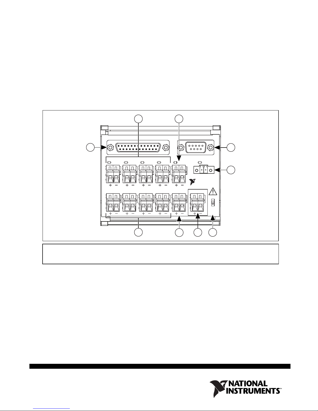
1 IN0–IN3 connectors
2 TRGIN connector
3 RS-232 connector
4 24V IN connector
5 SAFE MODE switch
6 24V OUT connector
7 LED DRV connector
8 OUT0–OUT3 connectors
9 CAMERA connector
Figure 1. Power and I/O Accessory for NI 177x Smart Cameras
The Power and I/O Accessory has the following features:
• 25-pin D-SUB connector and a 17-pin M12 to 25-pin D-SUB cable
• Spring terminals for each NI 177x Smart Camera I/O signal
• Spring terminal for 24 V output
• Safe mode switch
• User-replaceable fuses for open collector and current controlled outputs, RS-232, and
accessory power
• RS-232 connector for serial communication
• Built-in DIN rail clips for easy mounting
What You Need to Get Started
❑ Power and I/O Accessory kit, including the accessory and 17-pin M12 to 25-pin D-SUB
cable
❑ NI 177x Smart Camera
❑ NI 177x Smart Camera power supply (782032-01)
❑ (Optional) NI 9-pin female D-SUB to 9-pin female D-SUB null modem RS-232 cable
(part number 182238-xx)
❑ 12–28 AWG wire
❑ Wire cutter
❑ Wire insulation stripper
Related Documentation
The NI 177x Smart Camera User Manual, available from ni.com/manuals, contains
information you may find helpful as you set up and use the Power and I/O Accessory.
Installing the Power and I/O Accessory
Complete the following steps to install the Power and I/O Accessory:
1. Install the NI 177x Smart Camera and required software.
Caution Never touch the exposed pins of connectors.
2. Connect the included cable to the CAMERA connector on the Power and I/O Accessory
and the I/O connector on the NI 177x Smart Camera.
3. Connect signal wires to the spring terminals on the Power and I/O Accessory:
a. Strip 1/4 in. of insulation from the signal wire.
b. Depress the lever of the spring terminal.
c. Insert the wire into the terminal.
Refer to the spring terminal labels and the Signal Descriptions section for a description of
each signal.
Caution Do not connect input voltages greater than 24 VDC to the Power and I/O
Accessory. Input voltages greater than 24 VDC can damage the accessory, all devices
connected to it, and the host computer. National Instruments is not liable for damage
or injury resulting from such misuse.
NI 177x Power and I/O Acessory User Guide 2ni.com
 Loading...