

Page 1

PC-OPDIO-16
User Manual
Optically Isolated Digital I/O Board for the PC
May 1995 Edition
Part Number 320937A-01
© Copyright 1995 National Instruments Corporation.
All Rights Reserved.
Page 2

National Instruments Corporate Headquarters
6504 Bridge Point Parkway
Austin, TX 78730-5039
(512) 794-0100
Technical support fax: (800) 328-2203
(512) 794-5678
Branch Offices:
Australia (03) 879 9422, Austria (0662) 435986, Belgium 02/757.00.20, Canada (Ontario) (519) 622-9310,
Canada (Québec) (514) 694-8521, Denmark 45 76 26 00, Finland (90) 527 2321, France (1) 48 14 24 24,
Germany 089/741 31 30, Hong Kong 02 2637 5019, Italy 02/48301892, Japan (03) 3788-1921, Korea 02 596-7456,
Mexico 05 202 2544, Netherlands 03480-33466, Norway 32-84 84 00, Singapore 2265886, Spain (1) 640 0085,
Sweden 08-730 49 70, Switzerland 056/20 51 51, Taiwan 62 377 1200, U.K. 1635 523545
Page 3

Limited Warranty
The PC-OPDIO-16 is warranted against defects in materials and workmanship for a period of one year from the date
of shipment, as evidenced by receipts or other documentation. National Instruments will, at its option, repair or
replace equipment that proves to be defective during the warranty period. This warranty includes parts and labor.
The media on which you receive National Instruments software are warranted not to fail to execute programming
instructions, due to defects in materials and workmanship, for a period of 90 days from date of shipment, as
evidenced by receipts or other documentation. National Instruments will, at its option, repair or replace software
media that do not execute programming instructions if National Instruments receives notice of such defects during
the warranty period. National Instruments does not warrant that the operation of the software shall be uninterrupted
or error free.
A Return Material Authorization (RMA) number must be obtained from the factory and clearly marked on the
outside of the package before any equipment will be accepted for warranty work. National Instruments will pay the
shipping costs of returning to the owner parts which are covered by warranty.
National Instruments believes that the information in this manual is accurate. The document has been carefully
reviewed for technical accuracy. In the event that technical or typographical errors exist, National Instruments
reserves the right to make changes to subsequent editions of this document without prior notice to holders of this
edition. The reader should consult National Instruments if errors are suspected. In no event shall National
Instruments be liable for any damages arising out of or related to this document or the information contained in it.
EXCEPT AS SPECIFIED HEREIN, NATIONAL INSTRUMENTS MAKES NO WARRANTIES, EXPRESS OR IMPLIED,
AND SPECIFICALLY DISCLAIMS ANY WARRANTY OF MERCHANTABILITY OR FITNESS FOR A PARTICULAR
PURPOSE
OF
NATIONAL INSTRUMENTS WILL NOT BE LIABLE FOR DAMAGES RESULTING FROM LOSS OF DATA, PROFITS,
USE OF PRODUCTS, OR INCIDENTAL OR CONSEQUENTIAL DAMAGES, EVEN IF ADVISED OF THE POSSIBILITY
THEREOF
whether in contract or tort, including negligence. Any action against National Instruments must be brought within
one year after the cause of action accrues. National Instruments shall not be liable for any delay in performance due
to causes beyond its reasonable control. The warranty provided herein does not cover damages, defects,
malfunctions, or service failures caused by owner’s failure to follow the National Instruments installation, operation,
or maintenance instructions; owner’s modification of the product; owner’s abuse, misuse, or negligent acts; and
power failure or surges, fire, flood, accident, actions of third parties, or other events outside reasonable control.
. CUSTOMER’S RIGHT TO RECOVER DAMAGES CAUSED BY FAULT OR NEGLIGENCE ON THE PART
NATIONAL INSTRUMENTS SHALL BE LIMITED TO THE AMOUNT THERETOFORE PAID BY THE CUSTOMER.
. This limitation of the liability of National Instruments will apply regardless of the form of action,
Copyright
Under the copyright laws, this publication may not be reproduced or transmitted in any form, electronic or
mechanical, including photocopying, recording, storing in an information retrieval system, or translating, in whole
or in part, without the prior written consent of National Instruments Corporation.
Trademarks
®
LabVIEW
Product and company names listed are trademarks or trade names of their respective companies.
,
NI-DAQ®, RTSI®, and DAQPad™ are trademarks of National Instruments Corporation.
Page 4

WARNING REGARDING MEDICAL AND CLINICAL USE
OF NATIONAL INSTRUMENTS PRODUCTS
National Instruments products are not designed with components and testing intended to ensure a level of reliability
suitable for use in treatment and diagnosis of humans. Applications of National Instruments products involving
medical or clinical treatment can create a potential for accidental injury caused by product failure, or by errors on
the part of the user or application designer. Any use or application of National Instruments products for or involving
medical or clinical treatment must be performed by properly trained and qualified medical personnel, and all
traditional medical safeguards, equipment, and procedures that are appropriate in the particular situation to prevent
serious injury or death should always continue to be used when National Instruments products are being used.
National Instruments products are NOT intended to be a substitute for any form of established process, procedure, or
equipment used to monitor or safeguard human health and safety in medical or clinical treatment.
Page 5

Contents
____________________________________________________
About This Manual.............................................................................................................ix
Organization of This Manual.........................................................................................ix
Conventions Used in This Manual................................................................................. x
National Instruments Documentation ........................................................................... xi
Related Documentation.................................................................................................. xi
Customer Communication............................................................................................. xi
Chapter 1
Introduction
About Your PC-OPDIO-16 Board.................................................................................1-1
What You Need to Get Started ......................................................................................1-1
Software Programming Choices....................................................................................1-2
Optional Equipment.......................................................................................................1-3
Cabling...........................................................................................................................1-4
Unpacking......................................................................................................................1-4
..........................................................................................................................1-1
LabVIEW and LabWindows/CVI Application Software..................................1-2
NI-DAQ Driver Software...................................................................................1-2
Register-Level Programming.............................................................................1-3
Chapter 2
Installation and Configuration
Hardware Installation.....................................................................................................2-1
Hardware Configuration ................................................................................................2-2
Bus-Related Configuration ................................................................................2-2
Plug and Play Mode...............................................................................2-2
Switchless Mode....................................................................................2-2
Base I/O Address Selection....................................................................2-2
Data Acquisition-Related Configuration ...........................................................2-3
NI-DAQ Software Installation.......................................................................................2-3
NI-DAQ Installation for DOS............................................................................2-3
NI-DAQ Installation for LabVIEW...................................................................2-3
NI-DAQ Installation for LabWindows/CVI......................................................2-4
NI-DAQ Installation for Windows ....................................................................2-5
Software Configuration..................................................................................................2-5
Configuring Your PC-OPDIO-16......................................................................2-5
Using DAQCONF..............................................................................................2-6
NI-DAQ Configuration File...................................................................2-6
Device Configuration in DAQCONF ....................................................2-7
DAQCONF Command-Line Flags........................................................2-8
Using WDAQCONF..........................................................................................2-8
.......................................................................................2-1
© National Instruments Corporation v PC-OPDIO-16 User Manual
Page 6

Contents
Chapter 3
Signal Connections
I/O Connectors...............................................................................................................3-2
Signal Connection Descriptions.........................................................................3-3
Optically Isolated Digital Output ..................................................................................3-4
Output Channels.................................................................................................3-4
Optically Isolated Digital Input......................................................................................3-6
Input Channels...................................................................................................3-6
Sensing DC Voltages.........................................................................................3-7
Sensing AC Voltages.........................................................................................3-7
Signal Isolation ..................................................................................................3-7
Signal Connection Example...............................................................................3-7
Reducing the Forward Current for 24 V Inputs.................................................3-8
Power-on Condition...........................................................................................3-8
.............................................................................................................3-1
Signal Isolation ......................................................................................3-4
Signal Connection Example...................................................................3-5
Increasing Switching Frequency for TTL Loads...................................3-6
Power-on Condition...............................................................................3-6
Chapter 4
Fundamentals of Building Applications with NI-DAQ
Building DOS Applications with NI-DAQ....................................................................4-1
Creating a DOS Application Using Microsoft C...............................................4-1
Example Programs.................................................................................4-2
Creating a DOS Application Using Visual Basic..............................................4-2
Running Your Application Inside the Visual Basic Environment.........4-4
Compiling and Running Your Visual Basic Application from the
DOS Prompt...........................................................................................4-4
Example Programs.................................................................................4-5
Creating a DOS Application Using Borland Turbo C++ or Borland C++ ........4-5
Example Programs.................................................................................4-6
Creating a DOS Application Using Borland Turbo Pascal................................4-6
Memory Requirement............................................................................4-7
Example Programs.................................................................................4-7
Building Windows Applications with NI-DAQ.............................................................4-7
The NI-DAQ Libraries.......................................................................................4-8
NI-DAQ Programming Considerations .............................................................4-8
Buffer Allocation...............................................................................................4-8
Huge (Greater Than 64 KB) Buffer Access...........................................4-9
String Passing.........................................................................................4-9
Parameter Passing..................................................................................4-9
Creating a Windows Application Using Borland C++......................................4-9
Example Programs.................................................................................4-10
Special Considerations...........................................................................4-10
Creating a Windows Application Using Microsoft Visual C++........................4-11
Special Considerations...........................................................................4-11
Creating a Windows Application Using Turbo Pascal......................................4-11
Example Programs.................................................................................4-12
Special Considerations...........................................................................4-12
PC-OPDIO-16 User Manual vi © National Instruments Corporation
Page 7

Creating a Windows Application Using Microsoft Visual Basic......................4-14
Example Programs.................................................................................4-14
Special Considerations...........................................................................4-14
Chapter 5
Theory of Operation
Functional Overview......................................................................................................5-1
Theory of Operation.......................................................................................................5-2
I/O Channel Interface Circuitry.........................................................................5-2
Digital I/O Circuitry...........................................................................................5-2
Optical Isolation Circuitry .................................................................................5-3
Using NI-DAQ Functions for Isolated Digital I/O............................................5-4
Using LabVIEW Data Acquisition Library for Digital I/O...............................5-5
Easy I/O VIs...........................................................................................5-5
Advanced VIs.........................................................................................5-5
Chapter 6
NI-DAQ Function Reference
Using NI-DAQ Functions..............................................................................................6-1
Status Codes.......................................................................................................6-1
Variable Data Types...........................................................................................6-1
Primary Types........................................................................................6-2
Programming Language Considerations............................................................6-2
Visual BASIC for DOS..........................................................................6-3
Borland Turbo Pascal.............................................................................6-3
Visual BASIC for Windows ..................................................................6-3
NI-DAQ for LabWindows/CVI.........................................................................6-4
Device Numbers.................................................................................................6-5
Function Descriptions....................................................................................................6-5
DIG_In_Line......................................................................................................6-5
DIG_In_Port.......................................................................................................6-6
DIG_Out_Line...................................................................................................6-7
DIG_Out_Port....................................................................................................6-8
Get_DAQ_Device_Info.....................................................................................6-9
Get_NI_DAQ_Version......................................................................................6-10
Init_DA_Brds.....................................................................................................6-11
Contents
Appendix A
Specifications
........................................................................................................................A-1
Appendix B
CP Clare LDA210 Data Sheet
........................................................................................B-1
Appendix C
Register-Level Programming
.........................................................................................C-1
Appendix D
Status Codes
© National Instruments Corporation vii PC-OPDIO-16 User Manual
..........................................................................................................................D-1
Page 8

Contents
Appendix E
Customer Communication
...............................................................................................E-1
Glossary......................................................................................................................Glossary-1
Index ................................................................................................................................. Index-1
Figures
Figure 1-1. The Relationship between the Programming Environment, NI-DAQ, and
Your Hardware......................................................................................................1-3
Figure 3-1. PC-OPDIO-16 I/O Connector Pin Assignments....................................................3-2
Figure 3-2. Signal Connection Example for Isolated Output....................................................3-5
Figure 3-3. Resistor in Parallel to Increase the Switching Frequency......................................3-6
Figure 3-4. Signal Connection Example for Isolated Input......................................................3-8
Figure 3-5. Reducing Input Current for 24 V Signals...............................................................3-8
Figure 5-1. PC-OPDIO-16 Block Diagram...............................................................................5-1
Figure 5-2. PC I/O Interface Circuitry Block Diagram of PC-OPDIO-16...............................5-2
Figure 5-3. Optical Isolation Circuitry for Input.......................................................................5-3
Figure 5-4. Optical Isolation Circuitry for Output....................................................................5-3
Tables
Table 6-1. Status Values...........................................................................................................6-1
Table 6-2. Primary Type Names...............................................................................................6-2
Table 6-3. LabWindows/CVI Function Tree for Data Acquisition
Using the PC-OPDIO-16 .........................................................................................6-4
PC-OPDIO-16 User Manual viii © National Instruments Corporation
Page 9

About This Manual
____________________________________________________
This manual describes the electrical and mechanical aspects of the PC-OPDIO-16 and contains
information concerning its installation, operation, and programming. The PC-OPDIO-16 is fully
compatible with industry standard Intel-Microsoft Plug and Play specification Version 1.0a.
The PC-OPDIO-16 is an optically isolated digital I/O board for PC/XT/AT and IBM Personal
System 2 (PS/2) models 25 and 30 computers. This board is designed for low-cost data
acquisition and control for applications in laboratory testing, production testing, and industrial
process monitoring and control.
Organization of This Manual
The PC-OPDIO-16 User Manual is organized as follows:
• Chapter 1, Introduction, describes the PC-OPDIO-16; lists what you need to get started;
describes the optional software and optional equipment; and explains how to unpack your
PC-OPDIO-16.
• Chapter 2, Installation and Configuration, contains instructions for installing the
PC-OPDIO-16, installing the NI-DAQ software, configuring your PC-OPDIO-16 board, and
cabling.
• Chapter 3, Signal Connections, describes the pin arrangement, signal names, and signal
connections on the PC-OPDIO-16.
• Chapter 4, Fundamentals of Building Applications with NI-DAQ, contains general
information about building NI-DAQ applications that run in DOS and Windows and explains
the nature of the files needed and the basics of making applications. You can skip this
chapter if you are an experienced NI-DAQ user.
• Chapter 5, Theory of Operation, describes the theory of operation for optically isolated
digital I/O on the PC-OPDIO-16. This chapter also discusses using NI-DAQ functions with
the PC-OPDIO-16 board.
• Chapter 6, NI-DAQ Function Reference, contains important information about how to apply
the NI-DAQ function descriptions in this manual to your programming language and
environment. This chapter also includes a detailed description of each NI-DAQ function that
supports the PC-OPDIO-16. You can skip this chapter if you are an experienced NI-DAQ
user.
• Appendix A, Specifications, lists the specifications of the PC-OPDIO-16.
• Appendix B, LDA210 Data Sheet, contains a manufacturer data sheet for the LDA210 solid
state current sensor (CP Clare Corporation). This sensor is used on the PC-OPDIO-16
isolated input port.
• Appendix C, Register-Level Programming, describes in detail the address and function of
each PC-OPDIO-16 register.
© National Instruments Corporation ix PC-OPDIO-16 User Manual
Page 10

About This Manual
• Appendix D, Status Codes, lists the status codes returned by NI-DAQ, including the name
and description.
• Appendix E, Customer Communication, contains forms you can use to request help from
National Instruments or to comment on our products.
• The Glossary contains an alphabetical list and description of terms used in this manual,
including abbreviations, acronyms, metric prefixes, mnemonics, and symbols.
• The Index alphabetically lists the topics in this manual, including the page where you can
find the topic.
Conventions Used in This Manual
The following conventions are used in this manual:
bold Bold text denotes menus, menu items, or dialog box buttons or options.
bold italic Bold italic text denotes a note, caution, or warning.
italic Italic text denotes emphasis on a specific board or on other important
information, a cross reference, or an introduction to a key concept.
monospace Text in this font denotes text or characters that are to be literally input
from the keyboard, sections of code, programming examples, and syntax
examples. This font is also used for the proper names of disk drives,
paths, directories, programs, subprograms, subroutines, device names,
functions, variables, filenames, and extensions, and for statements and
comments taken from program code.
NI-DAQ NI-DAQ refers to the NI-DAQ software for PC compatibles unless
otherwise noted.
PC PC refers to PC/XT/AT and IBM PS/2 models 25 and 30 computers.
Port A Port A refers to port A or port 0 (as in the NI-DAQ software portions of
this manual).
Port B Port B refers to port B or port 1 (as in the NI-DAQ software portions of
this manual).
< > Angle brackets containing numbers separated by an ellipsis represent a
range of values associated with a bit, port, or signal name (for example,
ACH<0..7> stands for ACH0 through ACH7).
Abbreviations, acronyms, metric prefixes, mnemonics, symbols, and terms are listed in the
Glossary.
PC-OPDIO-16 User Manual x © National Instruments Corporation
Page 11

About This Manual
National Instruments Documentation
The PC-OPDIO-16 User Manual is one piece of the documentation set for your data acquisition
system. You could have any of several types of manuals depending on the hardware and
software in your system. Use the manuals you have as follows:
• Your DAQ hardware user manuals—These manuals have detailed information about the
DAQ hardware that plugs into or is connected to your computer. Use these manuals for
hardware installation and configuration instructions, specification information about your
DAQ hardware, and application hints.
• Software manuals—Examples of software manuals you may have are the LabVIEW and
LabWindows
application software (LabVIEW or LabWindows/CVI) manuals or the NI-DAQ chapters in
this manual to help you write your application. If you have a large and complicated system,
it is worthwhile to look through the software manuals before you configure your hardware.
• Accessory manuals—If you are using accessory products, read the terminal block and cable
assembly installation guides. They explain how to physically connect the relevant pieces of
the system. Consult these guides when you are making your connections.
®
/CVI manual sets. After you set up your hardware system, use either the
Related Documentation
The following documents contain information that you may find helpful as you read this manual:
• IBM Personal Computer AT Technical Reference manual
• IBM Personal Computer XT Technical Reference manual
Customer Communication
National Instruments wants to receive your comments on our products and manuals. We are
interested in the applications you develop with our products, and we want to help if you have
problems with them. To make it easy for you to contact us, this manual contains comment and
configuration forms for you to complete. These forms are in Appendix E, Customer
Communication, at the end of this manual.
© National Instruments Corporation xi PC-OPDIO-16 User Manual
Page 12

Chapter 1 Introduction
This chapter describes the PC-OPDIO-16; lists what you need to get started; describes the
optional software and optional equipment; and explains how to unpack your PC-OPDIO-16.
About Your PC-OPDIO-16 Board
Thank you for purchasing the PC-OPDIO-16, which is an optically isolated digital I/O board for
PC/XT/AT and IBM Personal System 2 (PS/2) models 25 and 30 computers. Each board has
eight optically isolated digital inputs and eight optically isolated digital outputs. You can control
and sense digital levels up to 24 VDC. You can install the PC-OPDIO-16 in any 8-bit or 16-bit
expansion slot on a PC.
The low cost of a system based on the PC-OPDIO-16 makes it ideal for laboratory work in
industrial and academic environments. You can use the optically isolated digital I/O lines to
switch external devices, such as transistors and solid-state relays, and to read the status of
external digital logic. Because the PC-OPDIO-16 is optically isolated, you can decouple the
noise and harsh ground of the PC from the real-world signals and vice versa.
Your PC-OPDIO-16 board, used in conjunction with the PC, is a versatile, cost-effective
platform for laboratory test, measurement, and control.
Detailed specifications of the PC-OPDIO-16 are in Appendix A, Specifications.
What You Need to Get Started
To set up and use your PC-OPDIO-16, you will need the following:
PC-OPDIO-16 board
PC-OPDIO-16 User Manual
One of the following software packages and documentation:
LabVIEW
LabWindows/CVI
NI-DAQ software for PC compatibles, version 4.8 or later
CB-50 LP (low cost) or CB-50 I/O connector block with 0.5 or 1.0 m NB1 connector cable
Your computer
© National Instruments Corporation 1-1 PC-OPDIO-16 User Manual
Page 13

Introduction Chapter 1
Software Programming Choices
There are several options to choose from when programming your National Instruments DAQ
and SCXI hardware. You can use LabVIEW, LabWindows/CVI, or NI-DAQ.
LabVIEW and LabWindows/CVI Application Software
LabVIEW and LabWindows/CVI are innovative program development software packages for
data acquisition and control applications. LabVIEW uses graphical programming, whereas
LabWindows/CVI enhances traditional programming languages. Both packages include
extensive libraries for data acquisition, instrument control, data analysis, and graphical data
presentation.
LabVIEW features interactive graphics, a state-of-the-art user interface, and a powerful graphical
programming language. The LabVIEW Data Acquisition VI Library, a series of VIs for using
LabVIEW with National Instruments DAQ hardware, is included with LabVIEW. The
LabVIEW Data Acquisition VI Libraries are functionally equivalent to the NI-DAQ software.
LabWindows/CVI features interactive graphics, a state-of-the-art user interface, and uses the
ANSI standard C programming language. The LabWindows/CVI Data Acquisition Library, a
series of functions for using LabWindows/CVI with National Instruments DAQ hardware, is
included with the NI-DAQ software kit. The LabWindows/CVI Data Acquisition libraries are
functionally equivalent to the NI-DAQ software.
Using LabVIEW or LabWindows/CVI software will greatly reduce the development time for
your data acquisition and control application.
NI-DAQ Driver Software
The NI-DAQ driver software is included at no charge with all National Instruments DAQ
hardware. NI-DAQ is not packaged with SCXI or accessory products, except for the SCXI-1200.
NI-DAQ has an extensive library of functions that you can call from your application
programming environment. These functions include routines for analog input (A/D conversion),
buffered data acquisition (high-speed A/D conversion), analog output (D/A conversion),
waveform generation, digital I/O, counter/timer operations, SCXI, RTSI, self-calibration,
messaging, and acquiring data to extended memory.
NI-DAQ has both high-level DAQ I/O functions for maximum ease of use and low-level DAQ
I/O functions for maximum flexibility and performance. Examples of high-level functions are
streaming data to disk or acquiring a certain number of data points. An example of a low-level
function is writing directly to registers on the DAQ device. NI-DAQ does not sacrifice the
performance of National Instruments DAQ devices because it lets multiple devices operate at
their peak performance.
NI-DAQ also internally addresses many of the complex issues between the computer and the
DAQ hardware such as programming interrupts and DMA controllers. NI-DAQ maintains a
consistent software interface among its different versions so that you can change platforms with
PC-OPDIO-16 User Manual 1-2 © National Instruments Corporation
Page 14

Chapter 1 Introduction
minimal modifications to your code. Figure 1-1 illustrates the relationship between NI-DAQ and
LabVIEW and LabWindows/CVI. You can see that the data acquisition parts of LabVIEW and
LabWindows/CVI are functionally equivalent to the NI-DAQ software.
Conventional
Programming
Environment
(PC, Macintosh, or
Sun SPARCstation)
DAQ or
SCXI Hardware
LabVIEW
(PC, Macintosh, or
Sun SPARCstation)
NI-DAQ
Driver Software
LabWindows/CVI
(PC or Sun
SPARCstation)
Personal
Computer or
Workstation
Figure 1-1. The Relationship between the Programming Environment,
NI-DAQ, and Your Hardware
Register-Level Programming
The final option for programming any National Instruments DAQ hardware is to write registerlevel software. Writing register-level programming software can be very time-consuming and
inefficient and is not recommended for most users.
Even if you are an experienced register-level programmer, consider using NI-DAQ, LabVIEW,
or LabWindows/CVI to program your National Instruments DAQ hardware. Using the NI-DAQ,
LabVIEW, or LabWindows/CVI software is as easy and as flexible as register-level
programming and can save weeks of development time.
Optional Equipment
You can use the following National Instruments product with your PC-OPDIO-16.
• CB-50 LP (low cost) or CB-50 I/O connector block with 0.5 or 1.0 m NB1 connector cable
For more information about optional equipment available from National Instruments, refer to
your National Instruments catalog or call the office nearest you.
© National Instruments Corporation 1-3 PC-OPDIO-16 User Manual
Page 15

Introduction Chapter 1
Cabling
National Instruments offers two cable termination accessory kits, the CB-50 and CB-50 LP, for
use with the PC-OPDIO-16. These kits include a terminated, 50-conductor, flat ribbon cable and
a connector block. You can attach signal input and output wires to screw terminals on the
connector blocks and connect to your PC-OPDIO-16 board I/O connector.
You can use the CB-50 or the CB-50 LP for initial prototyping of an application or in situations
where you frequently change your PC-OPDIO-16 board interconnections. When you develop a
final field wiring scheme, however, you may want to develop your own cable. This section
contains information and guidelines for designing custom cables.
The PC-OPDIO-16 I/O connector is a 50-pin male ribbon cable header. The manufacturer part
numbers of the headers National Instruments uses are as follows:
• Electronic Products Division/3M (part number 3596-5002)
• T&B/Ansley Corporation (part number 609-500)
The mating connector for the PC-OPDIO-16 is a 50-position, polarized, ribbon socket connector
with strain relief. National Instruments uses a polarized (keyed) connector to prevent inadvertent
upside-down connection to the PC-OPDIO-16. Recommended manufacturer part numbers for
this mating connector are as follows:
• Electronic Products Division/3M (part number 3425-7650)
• T&B/Ansley Corporation (part number 609-5041CE)
The following are the standard ribbon cables (50-conductor, 28 AWG, stranded) that can be used
with these connectors:
• Electronic Products Division/3M (part number 3365/50)
• T&B/Ansley Corporation (part number 171-50)
Unpacking
Your PC-OPDIO-16 board is shipped in an antistatic envelope to prevent electrostatic damage.
Several components on the board can be damaged by electrostatic discharge. To avoid damage
in handling the board, take the following precautions:
• Ground yourself via a grounding strap or by holding a grounded object.
• Touch the package to a metal part of your computer chassis before removing the board from
the package.
• Never attempt to touch the pins of the connectors.
• Remove the board from the package and inspect the board for loose components or any other
sign of damage. Notify National Instruments if the board appears damaged in any way. Do
not install a damaged board into your computer.
•Store your PC-OPDIO-16 board in the antistatic envelope when not in use.
PC-OPDIO-16 User Manual 1-4 © National Instruments Corporation
Page 16

Chapter 2 Installation and Configuration
This chapter contains instructions for installing the PC-OPDIO-16, installing the NI-DAQ
software, configuring your PC-OPDIO-16 board, and cabling.
Hardware Installation
You can install the PC-OPDIO-16 in any available 8-bit or 16-bit expansion slot in your
computer. The following are general installation instructions, but consult your PC user manual
or technical reference manual for specific instructions and warnings.
1. Turn off your computer.
2. Remove the top cover or access port to the I/O channel.
3. Remove the expansion slot cover on the back panel of the computer.
4. Record the PC-OPDIO-16 serial and revision numbers on the Hardware and Software
Configuration form in Appendix E, Customer Communication. You will need these numbers
when you install and configure your board.
5. Insert the PC-OPDIO-16 into an 8-bit or a 16-bit slot.
6. Screw the mounting bracket of the PC-OPDIO-16 to the back panel rail of the computer.
7. Check the installation.
8. Replace the cover.
The PC-OPDIO-16 board is installed. Follow the instructions in the NI-DAQ Software
Installation section to install NI-DAQ in your computer. If NI-DAQ is already installed, skip
that section and continue with the Software Configuration section later in this chapter.
If you are using LabVIEW, the software installation instructions are in your LabVIEW release
notes.
If you are using LabWindows/CVI, the software installation instructions are in Part 1,
Introduction to LabWindows/CVI, of the Getting Started with LabWindows/CVI manual.
© National Instruments Corporation 2-1 PC-OPDIO-16 User Manual
Page 17

Installation and Configuration Chapter 2
Hardware Configuration
The PC-OPDIO-16 is completely software configurable. Typically, two types of configuration
are performed on a DAQ board—bus related and data acquisition related. To configure the
PC-OPDIO-16 bus, you only have to set the base address.
Bus-Related Configuration
The PC-OPDIO-16 works in either a Plug and Play mode or a switchless mode. These modes
dictate how the base I/O address is determined and assigned to the board.
Plug and Play Mode
The PC-OPDIO-16 is fully compatible with the industry-standard Intel/Microsoft Plug and Play
Specification version 1.0. A Plug and Play system arbitrates and assigns resources through
software, freeing you from manually setting switches and jumpers. These resources include the
board base I/O address. The PC-OPDIO-16 is configured at the factory to request these
resources from the Plug and Play Configuration Manager.
The Configuration Manager receives all of the resource requests at start up, compares the
available resources to those requested, and assigns the available resources as efficiently as
possible to the Plug and Play boards. Application software can query the Configuration Manager
to determine the resources assigned to each board without your involvement. The Plug and Play
software is installed as a device driver or as an integral component of the computer BIOS.
Switchless Mode
You can use the PC-OPDIO-16 in a non-Plug and Play system as a switchless data acquisition
(DAQ) board. A non-Plug and Play system is a system in which the Configuration Manager has
not been installed and which does not contain any non-National Instruments Plug and Play
products. You use a configuration utility to enter the base address, and the application software
assigns it to the board.
Note: Avoid resource conflicts with non-National Instruments boards. For example, do not
configure two boards for the same base address.
Base I/O Address Selection
You can configure the PC-OPDIO-16 to use base addresses in the range of 100 to 3E0 hex. The
PC-OPDIO-16 occupies 8 bytes of address space and must be located on an 8-byte boundary.
Valid addresses include 100, 108, 110, ..., 3D8, 3E0 hex. This selection is software configured
and does not require you to manually change any settings on the board.
PC-OPDIO-16 User Manual 2-2 © National Instruments Corporation
Page 18

Chapter 2 Installation and Configuration
Data Acquisition-Related Configuration
The PC-OPDIO-16 supplies eight channels of optically isolated digital input and eight channels
of optically isolated digital output at the I/O connector.
NI-DAQ Software Installation
This following sections describe the installation of NI-DAQ on different platforms, including
DOS, LabVIEW, LabWindows/CVI, and Windows. Refer to the appropriate section and follow
the instructions to install the NI-DAQ software.
NI-DAQ Installation for DOS
The NI-DAQ distribution diskettes contain the installation utility SETUPDOS.EXE. Running
this installation utility copies the appropriate files to your computer. For example, if your
installation diskette is in drive A, type the following:
a:\setupdos
After installing NI-DAQ, continue by reading the Software Configuration section later in this
chapter to configure your PC-OPDIO-16.
NI-DAQ Installation for LabVIEW
The LabVIEW installation program may have installed the NI-DAQ software for you. However,
the NI-DAQ software that is included with your DAQ hardware may be a more recent revision
than the NI-DAQ software that LabVIEW installed.
After you have installed LabVIEW, you should run the NI-DAQ Windows installer
SETUPWIN.EXE, which will check the NI-DAQ version that LabVIEW installed against this
NI-DAQ version to ensure that the newest version is installed.
Note: You need NI-DAQ Version 4.8 or later to use your PC-OPDIO-16. Since LabVIEW
Version 3.1 installs NI-DAQ Version 4.6.1, you will need to install the NI-DAQ
software included with your PC-OPDIO-16 board if you are using LabVIEW Version
3.1 or earlier.
To upgrade NI-DAQ for LabVIEW, run the SETUPWIN program on Disk 1. One way to do this
is to select the File menu from the Program Manager Window, then select Run... and type in
a:\setupwin, assuming a: is the floppy disk drive containing Disk 1. When prompted, select
the Upgrade NI-DAQ for LabVIEW option.
Depending on your LabVIEW version, it may be necessary for NI-DAQ to update some of the
LabVIEW data acquisition VIs. If so, carefully follow the instructions given in the NI-DAQ
installer and the README.DAQ file.
© National Instruments Corporation 2-3 PC-OPDIO-16 User Manual
Page 19

Installation and Configuration Chapter 2
LabVIEW users are encouraged to use the Easy I/O VIs in LabVIEW. These VIs allow full
access to the PC-OPDIO-16 board functionality. For specific information on the VIs and on how
to write LabVIEW data acquisition applications, refer to your LabVIEW for Windows Data
Acquisition VI Reference Manual. The PC-OPDIO-16 boards may not be specifically mentioned
in your version of the LabVIEW manuals.
The following LabVIEW VIs are supported for the PC-OPDIO-16.
• Easy I/O VIs
– Read from Digital Line
– Read from Digital Port
– Write to Digital Line
– Write to Digital Port
• Configuration VIs
– Device Reset
– Get Device Information
– Set Device Information
• Advanced Digital I/O VIs
– DIO Port Read
– DIO Port Write
– DIO Single Read/Write
Follow instructions in the Software Configuration section later in this chapter to configure your
PC-OPDIO-16.
NI-DAQ Installation for LabWindows/CVI
To install NI-DAQ for LabWindows/CVI, run the SETUPWIN program on Disk 1. One way to
do this is to select the File menu from the Program Manager Window, then select Run... and
type in a:\setupwin, assuming a: is the floppy disk drive containing Disk 1. When
prompted, select the Install NI-DAQ for LabWindows/CVI option.
The NI-DAQ example programs for LabWindows/CVI are installed in the CVI\SAMPLES\DAQ
directory.
For LabWindows/CVI, the defined constants that several NI-DAQ functions use are in the
include file DATAACQ.H.
After installing NI-DAQ, continue by reading the Software Configuration section later in this
chapter to configure your PC-OPDIO-16.
PC-OPDIO-16 User Manual 2-4 © National Instruments Corporation
Page 20

Chapter 2 Installation and Configuration
NI-DAQ Installation for Windows
To install NI-DAQ for Windows, run the SETUPWIN program on Disk 1. One way to do this is
to select the File menu from the Program Manager Window, then select Run... and type in
a:\setupwin, assuming a: is the floppy disk drive containing Disk 1. When prompted, select
the Install/Upgrade NI-DAQ for Windows option.
Setupwin will install examples programs and support files for a variety of languages and
compilers. Choose all of the languages/compilers you plan to use. The NI-DAQ installer
examines your computer system to determine the system-dependent files that you need.
After installing NI-DAQ, continue by reading the Software Configuration section to configure
your PC-OPDIO-16.
Software Configuration
Before you begin your NI-DAQ application development, you must configure your
PC-OPDIO-16. NI-DAQ needs the device configuration information to program your hardware
properly.
You can configure your PC-OPDIO-16 board using DAQCONF or WDAQCONF. DAQCONF and
WDAQCONF are applications that you can use to view and configure your DAQ boards and SCXI
hardware for NI-DAQ to use. DAQCONF is a DOS-based application while WDAQCONF is
Windows-based. If you are using NI-DAQ in DOS, you need to run DAQCONF. If you are using
NI-DAQ in Windows or LabWindows/CVI, you should run WDAQCONF. Refer to the
appropriate section that follows according to the system you are using.
Configuring Your PC-OPDIO-16
The National Instruments switchless devices support switchless and jumperless configuration in
DOS and Windows. All resources including base address on these devices are fully software
configurable. No jumpers or DIP switches are needed to configure any of these resources.
The NI-DAQ installer will install a standalone executable called NI-PNP.EXE in the boot
directory of your root drive. This program detects and configures any switchless devices you
have in your computer. The program will run every time you boot from your autoexec.bat
file. After configuring your switchless hardware in the system, the program will generate an
NI-PNP.INI file in the same directory. This file contains information about the National
Instruments devices in your system, including switchless devices.
The DAQ configuration utility (WDAQCONF or DAQCONF) will read the NI-PNP.INI for
information and will automatically configure any switchless devices you have in your computer.
The utility will also deconfigure any previously configured switchless device that you have
removed from your computer. Running the configuration utility after installing a new switchless
device is important because you will be able to obtain a mapping for the newly installed device
into an NI-DAQ device number.
© National Instruments Corporation 2-5 PC-OPDIO-16 User Manual
Page 21

Installation and Configuration Chapter 2
When the configuration utility finds a new switchless device in your computer, it assigns the first
available device number to the new device. The utility also assigns default resources such as I/O
address. When you remove the device from your computer, the utility deallocates these resources
and the device number will contain an “empty device.”
Note: You must run the DAQ configuration utility after you install or remove any National
Instruments switchless devices such as the PC-OPDIO-16.
If you have plug and play software in your system, the behavior of the DAQ configuration utility
may change significantly. If the plug and play software in your system has its own separate
configuration utility, you must use the system configuration utility to configure all National
Instruments devices in your system. Subsequently, you must run the DAQ configuration utility
in order to assign NI-DAQ device numbers to any new devices. If you do not run the DAQ
configuration utility in this case, you will be unable to assign the base address for your
PC-OPDIO-16. The configuration utility that comes with your plug and play software is
responsible for assigning system resources to your National Instruments device. You will not be
able to change the I/O base address using WDAQCONF if you are using other Plug and Play
software to configure your PC-OPDIO-16.
Examples of plug and play software are a Plug and Play BIOS or the Intel Plug and Play Kit,
which includes the Intel Configuration Manager with its own configuration utility.
WDAQCONF performs a full set of tests before saving the device configuration to ensure the
device will operate correctly. If the device fails any of the tests, WDAQCONF reports the errors
and does not save the configuration.
DAQCONF does not perfom any such tests. The only way to find out if the configuration is
100 percent successful in DOS is to run a few NI-DAQ calls on the device.
Using DAQCONF
DAQCONF is a DOS-based application that you can use to view and configure your DAQ devices
for NI-DAQ to use. You need to run DAQCONF if you are using NI-DAQ in DOS. If you are
using NI-DAQ in Windows or LabWindows/CVI, you should skip to the Using WDAQCONF
section later in this chapter.
Locate DAQCONF in the same directory you installed NI-DAQ using the installation program.
Run the configuration utility by typing DAQCONF at the DOS prompt.
NI-DAQ Configuration File
The NI-DAQ configuration file holds all configuration information for your DAQ hardware.
The NI-DAQ configuration file in DOS is named ATBRDS.CFG. The first time you run
DAQCONF, it will create ATBRDS.CFG in your root directory. If you wish to create the
configuration file in a different directory, provide a path name when you run DAQCONF as in the
following example:
DAQCONF\PROJ_X
PC-OPDIO-16 User Manual 2-6 © National Instruments Corporation
Page 22

Chapter 2 Installation and Configuration
With this option, you can create multiple configuration files for different NI-DAQ applications
or projects; simply use the appropriate path name when you want to create a new configuration
file or view an existing one. Be sure to enter only the path name; the file will automatically be
created as ATBRDS.CFG in the specified directory.
When you run an NI-DAQ DOS application, NI-DAQ will look for the configuration file in the
current directory first. If NI-DAQ cannot find ATBRDS.CFG, it will look in the root directory of
the current drive. NI-DAQ will also read the device configuration that was stored in the EISA
system configuration utility.
DAQCONF takes a long time to start up. If you are not planning to use switchless devices with
NI-DAQ, you can start DAQCONF with the -x command-line option. This will disable autodetection of switchless devices in your computer.
Device Configuration in DAQCONF
DAQCONF opens with the board configuration panel. Perform the following steps to configure
your board.
1. Select a Device Number for your device. Use the F5 and F6 keys to scroll through the
choices. If the device number selected has a device assigned to it, you will see the current
settings for that device. To add a device, select a number without any device assigned to it.
You will use the device number in your NI-DAQ function calls to identify which device you
want to use.
2. Use the down arrow key to highlight the Device selection. Use the F5 and F6 keys to find
the correct device type.
3. You need to select the correct I/O base address. Use the up/down arrow keys to highlight the
fields, and then use the F5 and F6 keys to select the settings you wish to use.
4. You must save the configuration for this device before advancing to the next device number.
Press F10 to save. DAQCONF will test the configuration parameters before saving. If the test
fails, DAQCONF will not save the settings. You can disable the automatic test feature by
using the -t option on the command line when you invoke DAQCONF as in the following
example:
DAQCONF -t
© National Instruments Corporation 2-7 PC-OPDIO-16 User Manual
Page 23

Installation and Configuration Chapter 2
DAQCONF Command-Line Flags
You can use the following command-line flags with DAQCONF:
Command-Line Flag Description
-t Disable auto tests
-i Assume ISA bus computer
-e Assume EISA bus computer
-a Auto test for bus type
-u Usage
-x Disable auto-detection of switchless devices
-le Display in English (default)
-lj Display in Japanese (you must have a Japanese operating system)
You should enter multiple flags separately. For example:
daqconf -t -i
Using WDAQCONF
WDAQCONF is a Windows-based application that you can use to configure and view National
Instruments DAQ device settings for NI-DAQ Windows and LabWindows/CVI.
Locate WDAQCONF in the NI-DAQ Program Group in Windows. Run WDAQCONF by doubleclicking on its icon. If other NI-DAQ applications are running when you launch WDAQCONF,
you can only view your configuration.
When WDAQCONF starts, it tries to retrieve the current configuration from the WDAQCONF.CFG
file in the Windows directory. If WDAQCONF does not locate the file, WDAQCONF will create a
file.
When WDAQCONF starts, it also runs NI-PnP to find any Plug and Play boards in the system.
After WDAQCONF retrieves the current configuration, it displays all the devices installed in a
scrollable window. On the right of the window, you will see the current setting of the
highlighted device.
Perform the following steps to view and test your board. Press the F1 key any time to access the
online help.
1. Select a device number for your PC-OPDIO-16 by highlighting it in the scrollable window.
On the right side of the WDAQCONF window, you can see the current setting of the
PC-OPDIO-16. The device number you selected is the number you use to refer to the
PC-OPDIO-16 in your NI-DAQ applications.
2. Click on the Configure/Test Device #n button to bring out the configuration/test window.
PC-OPDIO-16 User Manual 2-8 © National Instruments Corporation
Page 24

Chapter 2 Installation and Configuration
3. Select the Device menu item to select your device type. Device type is the name of your
device. After you select the device type, you can see the default settings for your device.
4. Modify the base address if the default setting is not acceptable.
By default, WDAQCONF does not allow you to configure the same resource to different
devices. To disable this feature, go to the WDAQCONF main window and uncheck Resource
Checks under the Options menu item.
You cannot change the Resource Checks option if you are currently changing the
configuration of any devices. Make sure all your Device #n windows are closed before you
try to select this option.
5. To save your device setting, go to the File Configuration menu item in the configuration
window and select save. Before WDAQCONF saves your configuration, WDAQCONF runs
through a resource detection test for your configuration. It makes sure you have selected the
correct settings. WDAQCONF will not save the configuration if the test fails. You can disable
the feature by unchecking the Auto Test option under the Options menu item in the main
window.
When you save your device setting, WDAQCONF runs NI-PnP to check the Plug and Play
cards.
6. After saving your configuration, you can run simple tests on your PC-OPDIO-16. Under the
Test menu item in your configuration window, you can see all the tests you can perform.
• Configuration initiates the same test Auto Test uses.
• Digital I/O performs digital input read and digital output write operations.
7. After making sure all your DAQ device configurations are correct, you are ready to begin
your NI-DAQ development.
The Resources menu has an option called Write to Text File. Clicking on this option produces a
file named WDAQCONF.TXT in your Windows directory. This file, which describes your current
configuration, is useful when you call National Instruments technical support for assistance.
Your PC-OPDIO-16 is configured and ready for use.
© National Instruments Corporation 2-9 PC-OPDIO-16 User Manual
Page 25

Chapter 3 Signal Connections
This chapter describes the pin arrangement, signal names, and signal connections on the
PC-OPDIO-16.
Warning: Connections that exceed any of the maximum ratings of input or output signals
on the PC-OPDIO-16 may damage your PC-OPDIO-16 board and your
computer. This warning includes connecting any power signals to ground and
vice versa. National Instruments is
any such signal connections.
NOT liable for any damages resulting from
© National Instruments Corporation 3-1 PC-OPDIO-16 User Manual
Page 26

Signal Connections Chapter 3
I/O Connectors
Figure 3-1 shows the pin assignments for the PC-OPDIO-16 I/O connector.
VCCO0 1 2 VOUT0
COM0 3 4 VCCO1
VOUT1 5 6 COM1
VCCO2 7 8 VOUT2
COM2 9 10 VCCO3
VOUT3 11 12 COM3
VCCO4 13 14 VOUT4
COM4 15 16 VCCO5
VOUT5 17 18 COM5
VCCO6 19 20 VOUT6
COM6 21 22 VCCO7
VOUT7 23 24 COM7
IGND0 25 26 VIN0
IGND1 27 28 VIN1
IGND2 29 30 VIN2
IGND3 31 32 VIN3
IGND4 33 34 VIN4
IGND5 35 36 VIN5
IGND6 37 38 VIN6
IGND7 39 40 VIN7
NC 41 42 NC
NC 43 44 NC
NC 45 46 NC
NC 47 48 DGND
+5 V 49 50 DGND
Figure 3-1. PC-OPDIO-16 I/O Connector Pin Assignments
You can use the CB-50 LP (low cost) or CB-50 I/O connector block and the NB1 cable with the
PC-OPDIO-16 for your prototyping needs. The following table describes the connector pins on
the PC-OPDIO-16 I/O connector.
PC-OPDIO-16 User Manual 3-2 © National Instruments Corporation
Page 27

Chapter 3 Signal Connections
Signal Connection Descriptions
Pin Signal Name Description
1, 4, 7, 10,
13, 16, 19,
22
2, 5, 8, 11,
14, 17, 20,
23
3, 6, 9, 12,
15, 18, 21,
24
25. 27, 29,
31, 33, 35,
37, 39
26, 28, 30,
32, 34, 36,
38, 40
41–47 NC These pins are not connected.
48, 50 DGND Digital Ground—These pins are connected to the internal ground signal of the
49 +5 V +5 V—This output signal carries 1 A maximum output. It is referenced to
VCCO<0..7>
VOUT<0..7> Isolated Output, channels 0 through 7—This signal is the optically isolated
COM<0..7> Common, channels 0 through 7—This signal is the reference level from which
IGND<0..7> Isolated Input Ground, channels 0 through 7—This signal is the optically
VIN<0..7> Isolated Input Voltage, channels 0 through 7—This signal is the optically
Isolated Vcc for Output, channels 0 through 7—This signal is the Vcc for the
output channels. Range: +5 V to +24 V.
digital output line. VOUT7 is the MSB; VOUT0 is the LSB.
VOUTx is measured. It may be the isolated GND at the user end.
isolated ground for the input channels. The input signal will be referenced to
this ground.
isolated digital input line. VIN7 is the MSB; VIN0 is the LSB.
PC-OPDIO-16 board. This is not an isolated ground.
DGND.
© National Instruments Corporation 3-3 PC-OPDIO-16 User Manual
Page 28

Signal Connections Chapter 3
Optically Isolated Digital Output
I/O connector pins 1 through 24 shown in Figure 3-1 represent the optically isolated output
signal pins.
Output Channels
The optically isolated outputs of the PC-OPDIO-16 consist of a photo coupler and a load resistor.
The PC-OPDIO-16 has eight isolated output channels. Each channel has its own isolated ground
(COM), supply (VCCO), and output signal (VOUT). Figure 3-2 shows signal connection
examples for isolated output.
The maximum power ratings for the PC-OPDIO-16 are as follows:
• Maximum supply voltage (VCCO), 24 VDC
• Maximum output high current (IOH) = 250 µA
(VOUT = 3 V when VCCO = 5 V, or at VOUT = 22 V when VCCO = 24 V)
(shown in Figure 3-2a)
• Maximum output low current (I
Note: The data rate at the output is limited by the hardware. The maximum data rate
achievable with the PC-OPDIO-16 is 5 kHz. But the data rate may be slower than
5 kHz, depending on your software and CPU speed.
Signal Isolation
The COM, VCCO and VOUT signals of each channel are isolated from outputs of other channels
and also isolated from the PC-OPDIO-16 internal power and ground signals. These barriers
provide an isolation for voltages upto +24 VDC and protect the PC-OPDIO-16. Common-mode
voltages higher than the +24 VDC may damage your equipment.
Warning: You must not exceed the voltage limit of the VCCO referenced to their respective
COM signals. National Instruments is
signal connections that exceed these limits.
) = 7.0 mA at supply = 5 to 24 V (shown in Figure 3-2b)
OL
NOT liable for any damages resulting from
PC-OPDIO-16 User Manual 3-4 © National Instruments Corporation
Page 29

Chapter 3 Signal Connections
Signal Connection Example
Figure 3-2 shows signal connections for the load connected to an isolated output.
PC-OPDIO-16
5.6 kΩ5.6 kΩ5.6 kΩ
5.6 kΩ
VCCO
VOUT
COM
I
OH
Load
Isolated Ground
+
-
Supply
5–24 VDC
Digital Logic
+5 V
470 Ω
TLP121
Isolation
a. Load sinking current
Digital Logic
PC-OPDIO-16
5.6 kΩ5.6 kΩ5.6 kΩ
+5 V
470 Ω
Isolation
5.6 kΩ
VCCO
VOUT
COM
I
OL
Load
Isolated Ground
b. Load sourcing current
Figure 3-2. Signal Connection Example for Isolated Output
+
-
Supply
5–24 VDC
© National Instruments Corporation 3-5 PC-OPDIO-16 User Manual
Page 30

Signal Connections Chapter 3
Increasing Switching Frequency for TTL Loads
You can increase the switching frequency for the TTL loads by putting a resistor in parallel to
VCCO and VOUT. This parallel arrangement will reduce load resistance and increase switching
frequency. You can choose a value of Ro, as shown in Figure 3-3, in such a way that the
effective resistance from the parallel combination of 5.6 kΩ and Ro is about 1 kΩ. This
resistance will increase the switching frequency at the output to about 8 kHz, depending on your
software and the computer used.
PC-OPDIO-16
5.6 kΩ5.6 kΩ5.6 kΩ
TLP121
5.6 kΩ
VCC0
VOUT
COM
Ro
Load
5 V
+
Supply
-
Isolated Ground
Figure 3-3. Resistor in Parallel to Increase the Switching Frequency
Power-on Condition
At power up, VOUT will be high if the supply is connected to the VCCO terminal.
Optically Isolated Digital Input
I/O connector pins 25 through 40 shown in Figure 3-1 represent the optically isolated input
signal pins.
Input Channels
The optically isolated inputs of the PC-OPDIO-16 consist of a bidirectional light-emitting diode
and a resistor for current limiting. The PC-OPDIO-16 has eight isolated input channels. Each
channel has its own isolated ground and input signal.
Maximum input voltage (VIN) +24 VDC or 24 VAC
Note: Maximum data rate that can be sensed at the input is limited by the hardware to 1 kHz.
But the data rate that can be sensed at input may be slower than 1 kHz depending on
your software and CPU speed.
PC-OPDIO-16 User Manual 3-6 © National Instruments Corporation
Page 31

Chapter 3 Signal Connections
Sensing DC Voltages
When a positive or negative DC voltage with a magnitude of at least 2 V is referenced to the
IGND of a channel and is applied to an input of that channel, the PC-OPDIO-16 registers a logic
high for that input. If no voltage is present, the PC-OPDIO-16 will register a logic low for that
input. Thus, you can use the PC-OPDIO-16 to sense a wide range of DC signals—from digital
logic levels to DC power supply levels up to 24 V.
Sensing AC Voltages
The PC-OPDIO-16 senses a wide range of AC signals by registering a constant high while an
AC voltage (referenced to IGND) is present at an input. Signals with low amplitude and low
frequency appear as signals that are alternately turned on and off; therefore, the PC-OPDIO-16
alternately registers logic highs and logic lows for that signal. For sinusoidal signals, a 1 kHz
and higher frequency signal with a voltage of at least 4 Vrms returns a constant logic high level.
Signal Isolation
The VIN and IGND signals of each channel are isolated from the inputs of other channels and
are also isolated from the PC-OPDIO-16 internal power and ground signals. These barriers
provide an isolation for voltages up to +24 V and protect the PC-OPDIO-16. Voltages higher
than the +24 VDC may damage your equipment.
Warning: You must not exceed the voltage limit of the VIN signals referenced to their
respective IGND signals. National Instruments is
NOT liable for any damages
resulting from signal connections that exceed these limits.
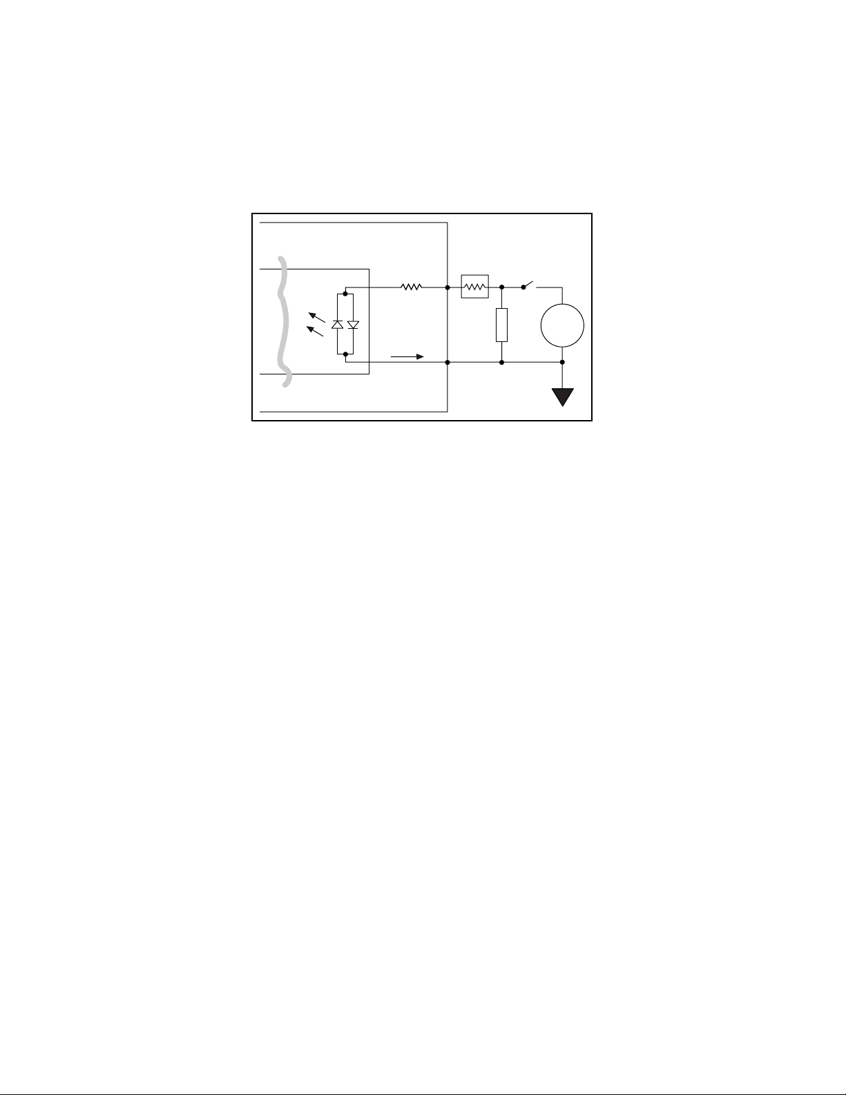
Signal Connection Example
Figure 3-4 shows signal connections for the load connected to an isolated input. In this figure,
the PC-OPDIO-16 is being used to sense that a load is being powered. The load is connected to
the power supply by means of a switch. This power supply can be AC or DC and can be any
voltage within the PC-OPDIO-16 range. When the switch is open, no current flows through the
load and no voltage is applied to the load or to the PC-OPDIO-16 input. The digital logic of the
PC-OPDIO-16 then registers a logic low for that channel. When the switch is closed, current
flows through the LED and the PC-OPDIO-16 registers a logic high for that channel.
+5 V
LDA210 (1/2)
2.7 kΩ
Digital Logic
Isolation
PC-OPDIO-16
3.3 kΩ
0.5 W
VIN
Supply
Load
IGND
Isolated Ground
Figure 3-4. Signal Connection Example for Isolated Input
© National Instruments Corporation 3-7 PC-OPDIO-16 User Manual
Page 32
Signal Connections Chapter 3
Reducing the Forward Current for 24 V Inputs
You can reduce the forward current, I
for 24 V input signals by adding a series resistance with
f
,
the 3.3 kΩ current-limiting resistor, as shown in Figure 3-5. The value of resistance should be
such that at least 1 mA flows through the LED. You can choose a value close to 20 kΩ for R
PC-OPDIO-16
Isolation
3.3 kΩ
0.5 W
I
f
IGND
VIN
R
s
Load
Isolated Ground
Supply
Figure 3-5. Reducing Input Current for 24 V Signals
Power-on Condition
At power up, the PC-OPDIO-16 will register a logic low if nothing is connected to the inputs.
.
s
PC-OPDIO-16 User Manual 3-8 © National Instruments Corporation
Page 33

Chapter 4 Fundamentals of Building Applications with NI-DAQ
_____________________________________________________________________________
This chapter contains general information about building NI-DAQ applications that run in DOS
and Windows and explains the nature of the files needed and the basics of making applications.
You can skip this chapter if you are an experienced NI-DAQ user.
Building DOS Applications with NI-DAQ
This section contains general information about building NI-DAQ applications that run in DOS
and explains the nature of the files needed and the basics of making applications using the
following compilers:
• Microsoft C
• Microsoft Visual Basic
• Turbo C++ and Borland C++
• Borland Turbo Pascal
In the DOS environment, a set of function libraries provides the NI-DAQ functions. You
compile and then link an application that makes calls to these functions to the appropriate library
for that compiler.
Creating a DOS Application Using Microsoft C
The NI-DAQ library for Microsoft C (NIDAQMSC.LIB) is compiled using the large memory
model. It is therefore essential that you install the large memory model of your Microsoft C
Compiler. If you have the files llibce.lib and llibc7.lib in the LIB directory of your
C compiler, you have the large memory model installed. Perform the following steps:
1. Create your source code. Follow the instructions in this manual and the NI-DAQ Function
Reference Manual for PC Compatibles when making calls to NI-DAQ functions. Be sure to
use the functional prototypes by including NIDAQ.H in your source file. You can find the
file NI_DAQ.H in the C_EX subdirectory under your NI-DAQ directory.
Note: You must call the USE function in your application before calling any other
NI-DAQ functions. This function causes portions of the NI-DAQ library that are
required to use your DAQ product to be included in your application. If you do not
call the appropriate USE function, your other NI-DAQ functions will return error -
421 (functionNotLinkedErr).
© National Instruments Corporation 4-1 PC-OPDIO-16 User Manual
Page 34

The Fundamentals of Building Applications with NI-DAQChapter 4
2. Compile your source code with the Microsoft C Compiler (Version 8.0 or later) and use the
large memory model, which you select when you include the /AL flag in the command line.
For example, to compile diginout.c and its support files, use the following commands:
cl /c /AL diginout.c
cl /c /AL getdev.c
cl /c /AL errprint.c
The /c flag directs the compiler to compile only.
3. Link your object file or files (using Microsoft Overlay Linker Version 3.61 or later) with the
NIDAQMSC.LIB library to create the executable application. For example, to link the
diginout.obj, getdev.obj, and errprint.obj files produced in step 2, use the
following command:
link /SEG:250 diginout getdev errprint,,,NIDAQMSC;
This link command will produce an diginout.exe executable.
Example Programs
You can find a set of example programs and the necessary header files in the NIDAQDOS\C_EX
directory.
Creating a DOS Application Using Visual Basic
To create an application that calls NI-DAQ functions, first create a source file for your
application using the following guidelines:
1. Add the following line to the beginning of the source file:
REM $INCLUDE: 'NIDAQ.INC'
This statement declares all of the NI-DAQ functions in the NI-DAQ library.
Note: If you are using NI-DAQ memory management functions, use the include file
called NIDAQR.INC, which has less restrictive prototypes.
PC-OPDIO-16 User Manual 4-2 © National Instruments Corporation
Page 35

Chapter 4 The Fundamentals of Building Applications with NI-DAQ
2. NI-DAQ library needs to allocate some memory for internal use. Therefore, you need to set
aside memory using the SETMEM statement. The amount of memory you need will depend
on which NI-DAQ functions you are using. If you have not set aside sufficient memory,
NI-DAQ functions will return a memory error (error code -98). For a description of the
SETMEM statement, refer to your BASIC manual. In the NI-DAQ Basic example programs,
a number between -2,000 and -10,000 is generally used as follows:
heap.size=SETMEM (-8000)
3. Follow the instructions in this chapter when making calls to the NI-DAQ functions.
Remember to substitute a period (.) wherever you see an underscore (_) in a function name.
For example, the function AO_Configure should be entered as AO.Configure in Visual
Basic applications.
Note: You must call the USE function in your application before calling any other
NI-DAQ functions. This function causes portions of the NI-DAQ library that
are required to use your DAQ product to be included in your application. If you
do not call the appropriate USE function, your other NI-DAQ functions will
return error -421 (functionNotLinkedErr).
Next, you can use either of the following approaches to run your application:
1. Run your application inside the Visual Basic environment. To do so, you must first create
and then load a Quick library of NI-DAQ functions when you enter Visual Basic
environment. The only case in which this approach will not work is when Visual Basic
returns out-of-memory error; in that case, use the second approach.
Note: Visual Basic returns an out-of-memory error either when you try to load the Quick
library or when you try to run your application. You may try to free up memory by
removing as many TSRs or device drivers as possible before entering the Visual
BasicC environment.
2. Compile and run your application from the DOS prompt. To do so, you use the BASIC
command-line compiler and linker.
These approaches are explained in detail in the following sections.
© National Instruments Corporation 4-3 PC-OPDIO-16 User Manual
Page 36

The Fundamentals of Building Applications with NI-DAQChapter 4
Running Your Application Inside the Visual Basic Environment
First, you must create an NI-DAQ Quick library.
MAKEQLB.BAT in the QLBUTIL subdirectory is useful for creating Quick libraries for Visual
Basic.
The steps for making a Quick library are as follows:
1. Edit NIDAQ.BAS. Remove the keyword REM from functions you want to include in the
Quick library.
2. Run this batch file by using the following command:
MAKEQLB VB
3. If all files needed to build the Quick library are found, and the linking was successful, the
batch file creates a Quick library in the NI-DAQ LIB subdirectory with a .QLB extension.
Next, load the Quick library when you enter the environment by using the following
command:
vbdos /l NIDAQVB
Note: Visual Basic returns an out-of-memory error either when you try to load the Quick
library or when you try to run your application. You may try to free up memory by
removing as many TSRs or device drivers as possible before entering the Visual Basic
environment.
After you are inside the environment, you can load the source file of your application and run it.
Compiling and Running Your Visual Basic Application from the DOS Prompt
The steps to run your application outside Visual Basic environment are as follows:
1. Compile your source code with the Visual Basic compiler. For example:
bc /O diginout.bas;
Note: NOT ENOUGH MEMORY—If the Visual Basic compiler does not have enough
memory to compile your application, you should first try to make available as much
conventional memory as possible. See your DOS manual for information on how
to do so. If you still cannot compile your application, you can edit the files
NIDAQ.INC (or NIDAQR.INC) and NIDAQCNS.INC to reduce their size.
2. Link the object file (using Microsoft Overlay Linker Version 3.61 or later) produced in step 1
with NIDAQMSC.LIB, SUP71.LIB, and the Visual Basic library. For example:
link /NOE /NOD /SEG:250 diginout,,, VBDCL10E NIDAQMSC SUP71;
You must include the SUP71 library in your link command because the DOS NI-DAQ
library NIDAQMSC.LIB is compiled using the Microsoft C compiler. Microsoft C support
functions are contained in the SUP71 library, which you can find in the NI-DAQ LIB
subdirectory. You should include the NI-DAQ LIB directory and the Basic LIB directory in
PC-OPDIO-16 User Manual 4-4 © National Instruments Corporation
Page 37

Chapter 4 The Fundamentals of Building Applications with NI-DAQ
your LIB environment variable so the linker can find the libraries. The following statement
is an example of how to set the LIB environment variable in your autoexec.bat file:
SET LIB=C:\NIDAQDOS\LIB;C:\VBDOS\LIB
Example Programs
You can find a set of example programs and the necessary header files in the
NIDAQDOS\BASIC_EX directory.
Creating a DOS Application Using Borland Turbo C++ or Borland C++
The NI-DAQ libraries for Borland Turbo C++ and Borland C++ are compiled using the large
memory model. Therefore, it is essential that you install the large memory model of your C++
compiler.
To create your application that calls NI-DAQ functions, you first create source code. Follow the
instructions in this chapter when making NI-DAQ function calls. Be sure to use the function
prototypes by including NIDAQ.H in your source file.
Note: You must call the USE function in your application before calling any other NI-DAQ
functions. This function causes portions of the NI-DAQ library that are required to use
your DAQ product to be included in your application. If you do not call the appropriate
USE function, your other NI-DAQ functions will return error -421
(functionNotLinkedErr).
To compile and run your application, it is recommended that you use the Integrated
Development Environment (IDE). You can find example project files created in version 3.1 in
the NI-DAQ C_EX directory. Newer versions of Borland C++ can use 3.1 project files.
To run your application using the IDE, you must follow these guidelines:
1. Open a project to manage your application code. Include the NI-DAQ library
NIDAQBC.LIB along with the source file in your project.
2. Choose Options | Compiler | Code Generation from the main menu. A dialog box will be
displayed. Set the Model button to Large. This will direct the compiler to use the large
memory model.
3. Choose Options | Directories from the main menu. A dialog box will be displayed that lets
you set the path for include files, libraries, and so on. Add the path to NI-DAQ LIB
subdirectory. Also add the path to the NI-DAQ C_EX directory to the include path.
© National Instruments Corporation 4-5 PC-OPDIO-16 User Manual
Page 38

The Fundamentals of Building Applications with NI-DAQChapter 4
If you are using Borland C++ version 4.0, you need to edit the definition of halloc in the
include file MALLOC.H in the include directory. To do so, go to line 65 in MALLOC.H and
remove the underscore from in front of farmalloc. The line should then read as follows:
#define halloc(num, size) (void huge *)farmalloc((unsigned
long)(num)* (size))
This change correctly maps the halloc function, which several NI-DAQ for DOS example
programs use.
Example Programs
You can find a set of example programs and the necessary header files in the NIDAQDOS\C_EX
directory. Not all of the examples will work with Borland C because some of them use plotting
routines written with Microsoft C. However, you can comment out the plotting operations and
use those example programs.
Creating a DOS Application Using Borland Turbo Pascal
To create a Turbo Pascal application that calls NI-DAQ functions, perform the following steps:
1. Create your source code. Follow the instructions in this chapter when making NI-DAQ
function calls.
Note: You must call the USE function in your application before calling any other
NI-DAQ functions. This function causes portions of the NI-DAQ library that are
required to use your DAQ product to be included in your application. If you do not
call the appropriate USE function, your other NI-DAQ functions will return error -
421 (functionNotLinkedErr).
2. Add the NIDAQ unit to the USES clause in your source code.
3. When compiling your program, be sure that the Turbo Pascal compiler can locate the
NI-DAQ units.
• If you are using the Integrated Development Environment (IDE), the directory containing
the NI-DAQ units should be specified as one of the Unit directories under the
Options | Directories menu. It is recommended that you choose Auto Save for the
Environment in the Options | Environment | Preferences menu to make the change
permanent.
• If you are using the command-line version of the compiler, specify the directory using the
/Uxxx switch.
• You may notice the compiler directive {$N+} in some of the NI-DAQ Turbo Pascal
example programs. This option directs the compiler to generate inline 80x87 code for
handling floating point numbers. This code is required by NI-DAQ routines that use
variables of type Double.
PC-OPDIO-16 User Manual 4-6 © National Instruments Corporation
Page 39

Chapter 4 The Fundamentals of Building Applications with NI-DAQ
Memory Requirement
If the Turbo Pascal interactive environment runs out of memory while compiling NI-DAQ
applications, try some or all of the following:
• Set the Turbo Pascal compile destination to disk.
• Set the Turbo Pascal link buffer to disk.
• Remove as many TSRs or device drivers as possible before compiling.
• It is sometimes possible to compile with less memory if, instead of specifying the main
NI-DAQ Turbo Pascal Unit (TPU), you specify only the needed sub-TPUs. To do this,
xxx
replace the USES NIDAQ; statement in your application with USES
or more of the sub-TPUs containing the function or functions you want. The
TPULIST.TXT file in the NI-DAQ PAS_EX directory contains a table that lists the TPUs
and the functions they contain.
Using these units instead of using nidaq.tpu prevents Turbo Pascal from having to bring all
the units into memory. Notice that the final executable file is only slightly smaller than a
program using nidaq.tpu because Turbo Pascal does not include any unused code in the final
executable file.
; where
xxx
is one
If you are not running out of memory during compilation (such as when using the TPCX to
compile), this method of bypassing nidaq.tpu may not offer you any significant advantage.
Example Programs
You can find a set of example programs and the necessary header files in the
NIDAQDOS\PAS_EX directory.
Building Windows Applications with NI-DAQ
This section contains general information about building NI-DAQ applications, describes the
nature of the NI-DAQ files used in building NI-DAQ applications, and explains the basics of
making applications using the following tools:
• Borland C++ for Windows
• Microsoft Visual C++
• Borland Turbo Pascal for Windows
• Microsoft Visual Basic
If you are not using the tools listed, consult your development tool reference manual for details
on creating applications that call DLLs.
© National Instruments Corporation 4-7 PC-OPDIO-16 User Manual
Page 40

The Fundamentals of Building Applications with NI-DAQChapter 4
The NI-DAQ Libraries
The NI-DAQ for Windows function libraries are DLLs, which means that NI-DAQ routines are
not linked into the executable files of applications. Only the information about the NI-DAQ
routines in NI-DAQ import libraries are stored in the executable files. For that reason,
Windows-executable files are usually smaller than DOS-executable files.
Import libraries contain information about their DLL exported functions. They indicate the
presence and location of the DLL routines. Depending on the development tools you are using,
you may give the DLL routines information through import libraries or through function
declarations.
Using functional prototypes is a good programming practice. That is why NI-DAQ is packaged
with functional prototype files for four different Windows development tools. The installation
utility copies the appropriate prototype files for the development tools you choose. If you are not
using any of the four development tools that NI-DAQ supports, you must create your own
functional prototype file.
NI-DAQ Programming Considerations
In addition to knowing how to use the NI-DAQ DLL, you should consider some special
problems that can occur when you access certain NI-DAQ routines. This section briefly
describes the nature of the problems. The following sections, which are specific to each
language, give the methods for solving the problems.
Buffer Allocation
Allocating memory in a Windows application is much more restrictive than is normally
encountered in a non-Windows application. Windows requires you to allocate all memory
through the Windows memory manager, and thus has its own memory-allocation functions. In
most cases, you should use these functions rather than the memory-allocation functions normally
used by a specific language.
PC-OPDIO-16 User Manual 4-8 © National Instruments Corporation
Page 41

Chapter 4 The Fundamentals of Building Applications with NI-DAQ
Huge (Greater Than 64 KB) Buffer Access
Buffers of allocated memory that exceed 64 KB are divided into 64 KB groups, or segments.
When you are accessing data within the buffer and you reach the end of one of these segments
and must reference the next segment, you need some way of finding the address of the next
segment. This event is called crossing a segment boundary. Some languages have special types
of pointers that make this crossing transparent to the programmer; other languages require you to
perform your own pointer arithmetic using a Windows-supplied constant to increment your
pointer address.
String Passing
When NI-DAQ for Windows routines call for a string that is passed as a parameter, the routines
expect a pointer to a null-terminated string. Some languages require special string handling to
support this type.
Parameter Passing
You can pass procedure or function parameters by value or by reference. Different languages
have different default settings. You must be sure to pass certain variables by value or by
reference to each NI-DAQ for Windows function.
Creating a Windows Application Using Borland C++
This section assumes that you will be using the Borland IDE to manage your code development.
For Windows programs in general, remember to follow this procedure:
1. Open a project module to manage your application code.
2. Create files of type .cpp (C++ source code).
3. Set Options\Application to Windows App to set options similar to those used in a module
definition file.
4. Create your resources using the Borland Whitewater Resource Toolkit. After you have
created the resources, save them into a .res file and add the .res file to the list of files for
the project window.
To use the NI-DAQ functions, you must use the NI-DAQ DLL. Follow this procedure:
1. Create your source file as you would for other Windows programs written in C++, calling
NI-DAQ functions as typical function calls.
2. Prototype any NI-DAQ routines used in your application. Include the NI-DAQ header file,
which prototypes all NI-DAQ routines, as shown in the following example:
#include "WDAQ_BC.H"
3. Add the NI-DAQ import library NIDAQ.LIB to the project module.
© National Instruments Corporation 4-9 PC-OPDIO-16 User Manual
Page 42

The Fundamentals of Building Applications with NI-DAQChapter 4
Example Programs
You can find some example programs and project files created in version 3.1
NIDAQWIN\BCCP_EX in the directory. Newer versions can use 3.1 project files.
Special Considerations
See Special Considerations in the Creating a Windows Application Using Borland C++ and the
Windows SDK section earlier in this chapter.
Buffer Allocation
To allocate memory, you can use the Windows functions GlobalAlloc() and
GlobalFree() or an NI-DAQ memory management function, NI_DAQ_Mem_Alloc or
NI_DAQ_Mem_Free. After allocation, to use a buffer of memory, you must lock memory with
GlobalLock() or NI_DAQ_Mem_Lock. After using the memory, you must unlock memory
with GlobalUnlock() or NI_DAQ_Mem_Unlock.
Note: If you allocate memory from GlobalAlloc(), call GlobalLock() and
GlobalPageLock() on the memory object before passing it to NI-DAQ.
Huge Buffer Access
When referencing memory buffers that may exceed 64 KB in size, use huge pointers to reference
the buffer. Any other pointer type will not perform the correct pointer increment when crossing
the 64 KB segment boundary. When you use the huge pointer, C automatically adjusts for
segment wraparound and normalizes the segment for pointer comparison.
String Passing
To pass strings, pass a pointer to the first element of the character array. Be sure that the string is
null-terminated.
Parameter Passing
By default, C passes parameters by value. Remember to pass pointers to the address of a
variable when you need to pass by reference.
PC-OPDIO-16 User Manual 4-10 © National Instruments Corporation
Page 43

Chapter 4 The Fundamentals of Building Applications with NI-DAQ
Creating a Windows Application Using Microsoft Visual C++
This section assumes that you will be using the Microsoft Visual Workbench to manage your
code development.
For Windows programs in general, remember to follow this procedure:
1. Open a project module to manage your application code.
2. Create files of type .cpp (C++ source code).
3. Create a module definition file, and add it to the project.
4. Create your resources using the App Studio. After you have created the resources, save
them into an .rc file and add the .rc file to the project.
To use the NI-DAQ functions, you must use the NI-DAQ DLL. Follow this procedure:
1. Create your source file as you would for other Windows programs written in C++, calling
NI-DAQ functions as typical function calls.
2. Prototype any NI-DAQ routines used in your application. Include the NI-DAQ header file,
which prototypes all NI-DAQ routines, as shown in the following example:
#include "WDAQ_C.H"
3. Add the NI-DAQ import library NIDAQ.LIB to the project module.
Special Considerations
See Special Considerations in the Creating a Windows Application Using Borland C++ and the
Windows SDK section earlier in this chapter.
Creating a Windows Application Using Turbo Pascal
For Windows programs in general, remember the following points:
1. Turbo Pascal for Windows 1.0 and 1.5 users: Create files of type .pas (Pascal source
code), including the Windows object units WObjects, WinTypes, and WinProcs.
Turbo Pascal 7.0 users: Create files of type .pas (Pascal source code), including the units
OWindows, ODialogs, WinTypes, and WinProcs.
2. Create your resources using the Borland Whitewater Resource Toolkit and save the resources
into a .res file. You must add this resource to the executable file by using the {$R ...}
compiler command.
© National Instruments Corporation 4-11 PC-OPDIO-16 User Manual
Page 44

The Fundamentals of Building Applications with NI-DAQChapter 4
3. Turn on the {$N+} compiler option to enable the extended floating-point types. You can
use this option whether or not you actually have a math coprocessor; if you do not have a
coprocessor, Turbo Pascal will emulate one for you. NI-DAQ functions expect to receive
8-byte floating-point values; with the $N option enabled, Turbo Pascal for Windows can
generate an 8-byte variable of type double. Otherwise, with this option disabled, Turbo
Pascal can only generate a 6-byte real, which is not compatible with NI-DAQ routines.
To use the NI-DAQ functions, you must use the NI-DAQ DLL. You will not be using the import
library (as in C or C++) to reference the DLL, however. Follow this procedure:
1. Create your source file as you would for any other Windows program written in Pascal,
calling NI-DAQ functions as typical function calls.
2. Prototype any NI-DAQ routines used in your application. Include the NI-DAQ include file,
which prototypes all NI-DAQ routines, as shown in the following example:
{$I WDAQ_TP.INC}
Note: This include file defines a special pointer to a double type called PDouble. Use
PDouble in a manner similar to that of the Turbo Pascal for Windows type
PInteger.
Example Programs
You can find a set of example programs and the necessary header files in the
NIDAQWIN\TP_EX directory.
Special Considerations
Buffer Allocation
To allocate memory, you can use the Windows functions GlobalAlloc() and
GlobalFree() or an NI-DAQ memory management function, NI_DAQ_Mem_Alloc or
NI_DAQ_Mem_Free. After allocation, to use a buffer of memory, you must lock memory with
GlobalLock() or NI_DAQ_Mem_Lock. After using the memory, you must unlock memory
with GlobalUnlock() or NI_DAQ_Mem_Unlock.
Note: If you allocate memory from GlobalAlloc(), call GlobalLock(), and
GlobalPageLock() on the memory object before passing it to NI-DAQ.
PC-OPDIO-16 User Manual 4-12 © National Instruments Corporation
Page 45

Chapter 4 The Fundamentals of Building Applications with NI-DAQ
Huge Buffer Access
Unlike C and C++, Turbo Pascal does not support huge pointers. Consequently, you must
perform your own pointer arithmetic when accessing memory buffers greater than 64 KB in size.
Essentially, whenever you increment a pointer to a buffer of memory, you should check the low
word of the pointer to see if it rolls over from $FFFF back to $0000. In this case, you need to
increment the high word of the pointer by a value given as Ofs(AHIncr). This increments the
Windows selector by the correct amount and references the next 64 KB segment. By using
record variants like PMemory used in DAQOP_TP.PAS, you can easily access both the pointer
and the high and low words of the pointer value. For more details, please see your Turbo Pascal
manuals.
String Passing
Normally, standard Pascal strings consist of an array of up to 255 characters, with the first byte
reserved for the length of the existing string. However, Windows and NI-DAQ functions expect
a null-terminated string, such as those used in the C language. Fortunately, Turbo Pascal for
Windows extends the string syntax to support the null-terminated string. To use this option,
check to ensure that the extended syntax compiler option {$X+} is enabled (which is the
default), and then declare the string as an array of characters, as in the following example:
type
Tfilename = array[0..80] of Char;
begin
err := DAQ_to_Disk(.., Tfilename, ...);
In addition, Turbo Pascal has a predefined pointer to a null-terminated string called PChar. To
pass a null-terminated string to a procedure or function, pass either a PChar pointer variable to
the string, or pass the name itself without an index.
Parameter Passing
By default, Pascal passes parameters by value. Include the var keyword if you need to pass by
reference.
Note: Functions such as DAQ_Monitor or Align_DMA_Buffer return variables
(newestPtIndex and AlignIndex) that index certain buffers. These values
assume that the index of your first index is zero. If your Pascal array starts at one, you
must add one to these variables if you use them.
© National Instruments Corporation 4-13 PC-OPDIO-16 User Manual
Page 46

The Fundamentals of Building Applications with NI-DAQChapter 4
Creating a Windows Application Using Microsoft Visual Basic
To use the NI-DAQ functions, you must use the NI-DAQ DLL. Follow this procedure:
1. Create your forms and code as you would for any other Visual Basic program, calling
NI-DAQ functions as typical function calls.
2. Prototype any NI-DAQ routines used in your application. You can do this by adding the
NI-DAQ header module WDAQ_VB.BAS in the NI-DAQ VB_EX directory. Go to the File
menu and select the Add File option. Then, using the file dialog box, find WDAQ_VB.BAS
and click on the OK button. Verify the file’s existence in the project window. This header
file will prototype all NI-DAQ functions.
Note: Use WDAQR_VB.BAS if you are using NI-DAQ memory management functions. Do
NOT add WDAQ_VB.BAS and WDAQR_VB.BAS to the same project.
In Visual Basic, function declarations have scope globally throughout the project. In
other words, you can define your prototypes in any module. The functions will be
recognized even in other modules.
Example Programs
You can find a set of example programs and the necessary header files in the
NIDAQWIN\VB_EX directory.
Special Considerations
Buffer Allocation
Visual Basic is quite restrictive when allocating memory. You allocate memory by declaring an
array of whatever data type with which you want to work. Visual Basic supports dynamic
memory allocation by allowing you to redimension an array to a variable size during run-time.
However, arrays are restricted to being less than 64 KB in total size (this translates to about
32,767 integers, 16,384 long integers, or 8,191 doubles). To break the 64 KB buffer size barrier,
you can use NI-DAQ memory management functions, with which you can use buffers larger
than 64 KB.
Pay special attention to NI-DAQ routines that modify string buffers, such as the
DAQ_DB_StrTransfer routine. You must ensure that the memory buffer is already allocated
to a size large enough to accommodate all of the requested samples. The following example
code copies a string buffer to disk:
:
open "filename.dat" for Binary As fh%
strBuffer$ = String$ (numSamples, 0) 'Allocate space for half
buff
:
daqErr% = DAQ_DB_StrTransfer (board%, strBuffer$, ptsTfr&,
status%)
PC-OPDIO-16 User Manual 4-14 © National Instruments Corporation
Page 47

Chapter 4 The Fundamentals of Building Applications with NI-DAQ
Put fh%, , strBuffer$
:
close fh%
:
Huge Buffer Access
Visual Basic does not support buffer allocation greater than 64 KB or huge buffer access. To
allocate and use buffers that are larger than 64 KB, consult the NI-DAQ memory management
functions.
String Passing
In Visual Basic, variables of data type String need no special modifications to be passed to
NI-DAQ for Windows functions. Visual Basic automatically appends a null character to the end
of a string before passing it (by reference, because strings cannot be passed by value in Visual
Basic) to a procedure or function.
Parameter Passing
By default, Visual Basic passes parameters by reference. Include the ByVal keyword if you
need to pass by value.
© National Instruments Corporation 4-15 PC-OPDIO-16 User Manual
Page 48

Chapter 5 Theory of Operation
This chapter describes the theory of operation for optically isolated digital I/O on the
PC-OPDIO-16. This chapter also discusses using NI-DAQ functions with the PC-OPDIO-16
board.
Functional Overview
The block diagram in Figure 5-1 shows a functional overview of the PC-OPDIO-16.
Data/
Address
Control
PC I/O Channel
+5 V
PC I/O
Channel
Interface
Plug and Play
Interface
Control
Address
Select and
Control
A<0..1>
Data
D<0..7>
Control
82C55A
Digital
I/O
1A Fuse
PA0
•
•
•
PA7
PB0
•
•
•
PB7
TLP121
TLP121
LDA210
LDA210
Figure 5-1. PC-OPDIO-16 Block Diagram
The following are the major components making up your PC-OPDIO-16 board:
VCCO0
VOUT0
COM0
•
•
•
•
Back Panel Connector
•
•
VIN7
IGND7
+5 V
DGND
• I/O channel interface circuitry
• Digital I/O circuitry
• Optical isolation circuitry
© National Instruments Corporation 5-1 PC-OPDIO-16 User Manual
Page 49

Theory of Operation Chapter 5
You can execute data acquisition functions by using the digital I/O circuitry. The internal data
and control buses interconnect the components. Optical isolation is attained by the optical
isolation circuitry.
Theory of Operation
I/O Channel Interface Circuitry
The PC I/O channel of the PC-OPDIO-16 consists of an address bus, a data bus, a Plug and Play
interface, and several control and support signals. The components making up the PC I/O
channel interface circuitry are shown in Figure 5-2.
Address Bus
Control Lines
PC I/O Channel
Data Bus
Timing
Interface
Data
Buffers
Plug and Play/
Address Decoder
Register Selects
Control and
Read/Write Signals
Internal Data Bus
Figure 5-2. PC I/O Interface Circuitry Block Diagram of PC-OPDIO-16
The circuitry consists of Plug and Play, address decoder, data buffers, and I/O channel interface
timing control circuitry. The circuitry monitors the address lines to generate the board enable
signal. The data buffers control the direction of data transfer on the bidirectional data lines based
on whether the transfer is a read or write.
Digital I/O Circuitry
The PC-OPDIO-16 supports 8-bit digital input and 8-bit digital output. The 16 bits are
configured as two 8-bit ports, one for input and the other for output. The digital I/O circuitry is
PC-OPDIO-16 User Manual 5-2 © National Instruments Corporation
Page 50

Chapter 5 Theory of Operation
designed around an 82C55A programmable peripheral interface (PPI). Two of the 82C55A ports
are used in the PC-OPDIO-16; port A is used for output, and port B is used for input.
Optical Isolation Circuitry
The eight bits of digital input are optically isolated by using four LDA210 solid-state photo
couplers. The optical isolation circuitry for input is shown in Figure 5-3 (only two input
channels, 0 and 1, are shown).
+5 V
+5 V
IGND0
3.3 kΩ
Port B
Digital Logic
3.3 kΩ
LDA210
VIN0
IGND1
VIN1
Figure 5-3. Optical Isolation Circuitry for Input
Each LDA210 provides optical isolation for two channels of input. The digital input signals
from VIN are buffered to improve and invert the logic levels before being passed to the 82C55A
PPI. The IGND pin of each channel connects to the isolated ground reference for the digital
signal of the corresponding channel.
Optical isolation of the eight bits of digital output is provided by eight Toshiba TLP121 photo
couplers. The optical isolation circuitry for output is shown in Figure 5-4 (only channel 0 is
shown).
5.6 kΩ5.6 kΩ5.6 kΩ
5.6 kΩ
VCCO0
VOUT0
COM0
Port A
Digital Logic
+5 V
470 Ω
TLP121
Figure 5-4. Optical Isolation Circuitry for Output
One photo coupler is used for optical isolation at each channel of output. Signals from port A of
the 82C55A PPI are buffered to improve logic levels. Digital output signals are available at the
VOUT pin of each channel. VCCO is connected to the voltage reference of the digital signal of
the corresponding channel and COM is the reference level from which VOUT is measured.
© National Instruments Corporation 5-3 PC-OPDIO-16 User Manual
Page 51

Theory of Operation Chapter 5
Using NI-DAQ Functions for Isolated Digital I/O
The C code block below illustrates the use of the NI-DAQ digital input and output calls
supported by the PC-OPDIO-16 board. The series of calls outputs the binary pattern 11110000
from port 0 and input a pattern from port 1. Next, line 4 is toggled to zero on port 0 and line 4 is
read by port 1. Be aware that calling Dig_Prt_Config for one port will effect the output of
the other port. Always configure both ports before inputting or outputting patterns. The
calls made and the order will be the same for Basic and Pascal users although the syntax will
differ. Refer to the function reference section for complete explanations of the parameters and
the functions.
/*--------------------------------------------\
Initializes support for PC-OPDIO-16
DOS users only can call this function
Note: The PC-OPDIO-16 is functionally similar
to the AT-DIO-24, so call USE_DIO_24
to initialize it
\--------------------------------------------*/
error = USE_DIO_24();
if (error < 0) exit (error);
/*---------------------------------------------\
output 11110000 from port 0
\---------------------------------------------*/
error = DIG_Out_Port(device, 0, 0xF0);
if (error < 0) exit (error);
/*------------------------------------------------\
read port 1
\------------------------------------------------*/
error = DIG_In_Port(device, 1, &pattern);
if (error < 0) exit (error);
/*---------------------------------------------\
ask port 0 to toggle line 4 to be 0
\---------------------------------------------*/
error = DIG_Out_Line(device, 0, 4, 0);
if (error < 0) exit (error);
/*---------------------------------------------\
ask port 1 to read line 4
\---------------------------------------------*/
error = DIG_In_Line(device, 1, 4, &state);
if (error < 0) exit (error);
PC-OPDIO-16 User Manual 5-4 © National Instruments Corporation
Page 52

Chapter 5 Theory of Operation
Using LabVIEW Data Acquisition Library for Digital I/O
LabVIEW users are encouraged to use the Easy I/O VIs in LabVIEW. They allow full access to
the PC-OPDIO-16 board functionality. For specific information on the VIs and how to write
LabVIEW data acquisition applications refer to your LabVIEW Data Acquisition VI Reference
Manual for Windows. The PC-OPDIO-16 board may not be specifically mentioned in your
version of the LabVIEW manuals.
The easiest way to use digital input and output in LabVIEW is to call the Easy I/O VIs Read
from Digital Line, Read from Digital Port, Write to Digital Line, or Write to Digital Port.
Note that configuring a port will cause the output of the other port to change to zero. The Easy
I/O VIs will configure the port in some cases.
You can also call the Advanced Digital I/O VIs DIO Port Read, DIO Port Write, and DIO Single
Read/Write to input and output digital data from the ports.
The following digital input and output LabVIEW VIs are supported for the PC-OPDIO-16 board.
Easy I/O VIs
• Read from Digital Port
• Read from Digital Line
• Write to Digital Port
• Write to Digital Line
Advanced VIs
• DIO Single Read/Write
• DIO Port Write
• DIO Port Read
© National Instruments Corporation 5-5 PC-OPDIO-16 User Manual
Page 53

Chapter 6 NI-DAQ Function Reference
This chapter contains important information about how to apply the NI-DAQ function
descriptions in this manual to your programming language and environment. This chapter also
includes a detailed description of each NI-DAQ function that supports the PC-OPDIO-16. You
can skip this chapter if you are an experienced NI-DAQ user.
Using NI-DAQ Functions
Status Codes
Every NI-DAQ function is of the following form:
status = Function_Name (parameter 1, parameter 2, parameter n)
where n = 0. Each function returns a value in the status variable that indicates the success or
failure of the function, as shown in Table 6-1.
Table 6-1. Status Values
Status Result
Negative Function did not execute because of an error
Zero Function completed successfully
Positive Function executed but with a potentially serious side effect
In DOS and Windows, status is a 2-byte integer.
Variable Data Types
The NI-DAQ Application Programming Interface (API) is almost identical in DOS and
Windows, except for some of the parameter data types. Every function description has a
parameter table that lists the data types in each of the environments. LabWindows uses the same
types as DOS, and LabWindows/CVI uses the same types as Windows. The following sections
describe the notation used in those parameter tables and throughout the manual for variable data
types.
© National Instruments Corporation 6-1 PC-OPDIO-16 User Manual
Page 54

NI-DAQ Function Reference Chapter 6
Primary Types
Table 6-2 shows the primary type names and their ranges.
Table 6-2. Primary Type Names
Type Description
Name
I16 16-bit signed
integer
U16 16-bit unsigned
integer
I32 32-bit signed
integer
U32 32-bit unsigned
integer
F32 32-bit single-
precision
floating point
F64 64-bit double-
precision
floating point
Range Type
C BASIC Pascal
-32,768 to 32,767 short Integer (for example:
deviceNum%)
0 to 65,535 unsigned
short
-2,147,483,648 to
2,147,483,647
0 to 4,294,967,295 unsigned
-3.402823 x 1038 to
3.402823 x 10
-1.797683134862315 x
308
10
to
1.797683134862315 x
308
10
38
long Long integer (for
long
float Single-precision floating
double Double-precision
Not supported by
BASIC. For functions
that require unsigned
integers, use the signed
integer type instead.
See the I16 description.
example: count&)
Not supported by
BASIC. For functions
that require unsigned
long integers, use the
signed long integer type
instead. See the I32
description.
point (for example:
num!)
floating point (for
example: voltage#)
Integer
Word
Longint
Not supported
by Pascal. For
functions that
require
unsigned long
integers, use
the signed long
integer type
instead. See
the I32
description.
Single
Double
Programming Language Considerations
Apart from the data type differences, there are a few language-dependent considerations you
need to be aware of when you use the NI-DAQ API. Please read the following sections that
apply to your programming language.
Note: Be sure to include the NI-DAQ function prototypes by including the appropriate
NI-DAQ header file in your source code.
PC-OPDIO-16 User Manual 6-2 © National Instruments Corporation
Page 55

Chapter 6 NI-DAQ Function Reference
Visual Basic for DOS
All of the function names listed in this manual have underscores (_) in the names to delineate
words. In Visual Basic the underscore is illegal in a symbol name, so you must replace each
underscore in the NI-DAQ function names with a period when you use function names in your
program.
When you pass arrays to the NI-DAQ functions using Visual Basic in DOS, you simply pass the
array name followed by the appropriate type character and empty parentheses. For example, you
would call the DAQ_Start function using the following syntax:
status% = DAQ.Start (device%, chan%, gain%, buffer%(), count&,
timebase%, sampInterval%)
When calling an NI-DAQ function that takes no parameters, do not append the parentheses, (), to
the function name. Following is an example of how to call an NI-DAQ function that takes no
parameters:
err%=USE.E.Series.DIO
Borland Turbo Pascal
When you pass arrays to NI-DAQ functions using Borland Turbo Pascal in DOS or Windows,
you need to pass a pointer to the array. You can either declare an array and pass the array
address to the NI-DAQ function, or you can declare a pointer, dynamically allocate memory for
the pointer, and pass the pointer directly to the NI-DAQ function. For example,
var
buffer : array [1..1000] of Integer;
bufPtr : ^Integer;
status := DAQ_Start (device, chan, gain, @buffer, count,
timebase, sampInterval);
or
(* allocate memory for bufPtr first *)
status := DAQ_Start (device, chan, gain, bufPtr, count, timebase,
sampInterval);
Visual BASIC for Windows
NI-DAQ Constants Include File
The file NIDAQCNS.INC contains definitions for constants required for some of the NI-DAQ
functions. You should use the constants symbols in your programs; do not use the numerical
values.
In Visual Basic for Windows, you can load the entire NIDAQCNS.INC file into the global
module. You will then be able to use any of the constants defined in this file in any module in
your program.
© National Instruments Corporation 6-3 PC-OPDIO-16 User Manual
Page 56

NI-DAQ Function Reference Chapter 6
To do so, go to the Project window and choose the Global module, then choose Load Text
from the Code menu. Select NIDAQCNS.INC , which is in the NIDAQWIN\VB_EX directory.
Choose Replace or Merge, depending on how you want to incorporate this file into your global
module.
This procedure is identical to the procedure you would follow when loading the Visual Basic file
CONSTANT.TXT. Search on the word CONSTANT for more information from the Visual Basic
on-line help. Alternatively, you can cut and paste individual lines from this file and place them
in the module where you need them. However, if you do so, you should remove the word Global
from the CONSTANTS definition. For example,
GLOBAL CONST ND_OUTPUT_POLARITY& = 27240
would become:
CONST ND_OUTPUT_POLARITY& = 27240
NI-DAQ for LabWindows/CVI
In the LabWindows/CVI environment, NI-DAQ functions appear in the Data Acquisition
function panels under the Libraries menu. Each function panel represents an
NI-DAQ function, which is displayed at the bottom of the panel. The function panels have help
text for each function and each parameter.
Table 6-3 shows the LabWindows/CVI function panel and the name of the corresponding
NI-DAQ function which supports the PC-OPDIO-16 board.
Table 6-3. LabWindows/CVI Function Tree for Data Acquisition
Using the PC-OPDIO-16
LabWindows/CVI Function Panel NI-DAQ Function
Data Acquisition
Initialization/Utilities
Initialize Board Init_DA_Brds
Get Device Information Get_DAQ_Device_Info
Get DAQ Library Version Get_NI_DAQ_Version
Digital Input/Output
Read Port DIG_In_Port
Read Line DIG_In_Line
Write Port DIG_Out_Port
Write Line DIG_Out_Line
Initialization/Utilities is a class of functions used for general board initialization and
configuration, for configuration retrieval, and for setting NI-DAQ properties. This class also
contains several useful utility functions.
Digital Input/Output is a class of functions that perform digital input and output operations.
PC-OPDIO-16 User Manual 6-4 © National Instruments Corporation
Page 57

Chapter 6 NI-DAQ Function Reference
Device Numbers
The first parameter to almost every NI-DAQ function is the device number of the DAQ device
you want NI-DAQ to use for the given operation. After you have followed the instructions in
Chapter 2, Installation and Configuration, the configuration utility displays the device number
for each device you have installed in the system. You can use the configuration utility to verify
your device numbers. You can use multiple DAQ devices in one application; to do so, simply
pass the appropriate device number to each function.
Function Descriptions
The following is an alphabetically ordered list of NI-DAQ functions that support the
PC-OPDIO-16. Remember that port A is the output port and port B is the input port, so you will
perform digital writes to port A and digital reads from port B. However, you may wish to
perform a digital read from port A to determine the value of a previous write.
DIG_In_Line
Format
status = DIG_In_Line (deviceNumber, port, line, state)
Purpose
Returns the digital logic state of the specified digital line in the specified port.
Parameters
Direction Name Type Description
Input deviceNumber I16 assigned by configuration utility
port I16 digital I/O port number
line I16 digital line to be read
Output state I16 returns the digital logic state
Parameter Discussion
port is the digital I/O port number.
Range: 0 through 1
Port A = 0
Port B = 1
Note: You will normally use input port B with this function.
line is the digital line to be read.
Range: 0 through 7
state returns the digital logic state of the specified line.
0: The specified digital line is at a digital logic low.
1: The specified digital line is at a digital logic high.
© National Instruments Corporation 6-5 PC-OPDIO-16 User Manual
Page 58

NI-DAQ Function Reference Chapter 6
Note to C Programmers: state is a pass-by-reference parameter.
Using This Function
DIG_In_Line returns the digital logic state of the specified digital line in the specified port. If
the specified port is configured as an input port, NI-DAQ determines the state of the specified
line by the way in which some external device is driving it. If the port is configured as an output
port and the port has read-back capability, NI-DAQ determines the state of the line by the way in
which that port itself is driving it.
DIG_In_Port
Format
status = DIG_In_Port (deviceNumber, port, pattern)
Purpose
Returns digital input data from the specified digital I/O port.
Parameters
Direction Name Type Description
Input deviceNumber I16 assigned by configuration utility
port I16 digital I/O port number
Output pattern I16 8-bit digital data read from the specified port
Parameter Discussion
port is the digital I/O port number.
Range: 0 through 1
Port A = 0
Port B = 1
Note: You will normally use input port B with this function.
pattern returns the 8-bit digital data read from the specified port. NI-DAQ maps pattern to the
digital input lines making up the port such that bit 0, the least significant bit, corresponds to
digital input line 0. The high eight bits of pattern are always 0.
Note to C Programmers: pattern is a pass-by-reference parameter.
Using This Function
DIG_In_Port reads digital data from the port on the specified board. If the port is configured
as an input port, reading that port returns the digital logic state of the lines as some external
device is driving them. If the port is configured as an output port and has read-back capability,
reading the port returns the output state of that port, along with a warning that NI-DAQ has read
an output port.
PC-OPDIO-16 User Manual 6-6 © National Instruments Corporation
Page 59

Chapter 6 NI-DAQ Function Reference
DIG_Out_Line
Format
status = DIG_Out_Line (deviceNumber, port, line, state)
Purpose
Sets or clears the specified digital output line in the specified digital port.
Parameters
Direction Name Type Description
Input deviceNumber I16 assigned by configuration utility
port I16 digital I/O port number
line I16 digital output line
state I16 new digital logic state
Parameter Discussion
port is the digital I/O port number.
Range: 0 through 1
Port A = 0
Port B = 1
Note: You will normally use output port A with this function.
line is the digital output line to be written to.
Range: 0 through 7
state contains the new digital logic state of the specified line.
0: The specified digital line is set to digital logic low.
1: The specified digital line is set to digital logic high.
Using This Function
DIG_Out_Line sets the digital line in the specified port to the specified state. The remaining
digital output lines making up the port are not affected by this call. If you have not configured
the port as an output port, NI-DAQ does not perform the operation and returns an error. You
must call DIG_Prt_Config to configure a digital I/O port as an output port.
© National Instruments Corporation 6-7 PC-OPDIO-16 User Manual
Page 60

NI-DAQ Function Reference Chapter 6
DIG_Out_Port
Format
status = DIG_Out_Port (deviceNumber, port, pattern)
Purpose
Writes digital output data to the specified digital port.
Parameters
Direction Name Type Description
Input deviceNumber I16 assigned by configuration utility
port I16 digital I/O port number
pattern I16 8-bit digital pattern for the data written
Parameter Discussion
port is the digital I/O port number.
Range: 0 through 1
Port A = 0
Port B = 1
Note: You will normally use output port A with this function.
pattern indicates the 8-bit digital pattern for the data written to the specified port. NI-DAQ
ignores the high eight bits of pattern. NI-DAQ maps the low eight bits of pattern to the digital
output lines making up the port so that bit 0, the least significant bit, corresponds to digital
output line 0.
Using This Function
DIG_Out_Port writes the specified digital data to the port on the specified board. If you have
not configured the specified port as an output port, NI-DAQ does not perform the operation and
returns an error. You must call DIG_Prt_Config to configure a digital I/O port as an output
port.
PC-OPDIO-16 User Manual 6-8 © National Instruments Corporation
Page 61

Chapter 6 NI-DAQ Function Reference
Get_DAQ_Device_Info
Format
status = Get_DAQ_Device_Info (deviceNumber, infoType, infoValue)
Purpose
Allows you to retrieve parameters pertaining to the device operation.
Parameters
Direction Name Type Description
Input deviceNumber I16 assigned by configuration utility
infoType U32 type of information you want to retrieve
Output infoValue U32 retrieved information
Parameter Discussion
The legal range for the infoType is given in terms of constants that are defined in a header file.
The header file you should use depends on the language you are using:
• C programmers—NIDAQCNS.H (DATAACQ.H for LabWindows/CVI)
• BASIC programmers—NIDAQCNS.INC
• Pascal programmers—NIDAQCNS.PAS
Use infoType to let NI-DAQ know which parameter you want to retrieve. infoValue will reflect
the value of the parameter. infoValue will be given either in terms of constants from the header
file or as numbers, as appropriate.
infoType can be one of the following:
infoType Description
ND_BASE_ADDRESS Base address, in hexadecimal, of the device specified
by deviceNumber.
ND_DEVICE_TYPE_CODE Type of the device specified by deviceNumber. See
Init_DA_Brds for a list of device type codes.
Note to C Programmers: infoValue is a pass-by-reference parameter.
© National Instruments Corporation 6-9 PC-OPDIO-16 User Manual
Page 62

NI-DAQ Function Reference Chapter 6
Get_NI_DAQ_Version
Format
status = Get_NI_DAQ_Version (version)
Purpose
Returns the version number of the NI-DAQ library.
Parameter
Direction Name Type Description
Output version U32 version number assigned
Using This Function
Get_NI_DAQ_Version returns a 4-byte value in the version parameter. The upper two bytes
are reserved and the lower two bytes contain the version number. Always bitwise AND the
4-byte value with FFFF in hex before using the version number. For version 4.8.0, the lower
2-byte value is 480 in hex.
Note to C Programmers: version is a pass-by-reference parameter.
PC-OPDIO-16 User Manual 6-10 © National Instruments Corporation
Page 63

Chapter 6 NI-DAQ Function Reference
Init_DA_Brds
Format
status = Init_DA_Brds (deviceNumber, deviceNumberCode)
Purpose
Initializes the hardware and software states of a National Instruments DAQ board to its default
state, and then returns a numeric board code that corresponds to the type of board initialized.
Any operation that the board is performing is halted. This function is called automatically and
does not have to be explicitly called by your application. This function is useful for reinitializing
the board hardware, for reinitializing the NI-DAQ software, and for determining which board has
been assigned to a particular slot number. Init_DA_Brds will clear all configured messages
for the board just as if you called Config_DAQ_Event_Message with a mode of 0.
Parameters
Direction Name Type Description
Input deviceNumber I16 assigned by configuration utility
Output deviceNumberCode I16 type of board
Parameter Discussion
deviceNumberCode indicates the type of board initialized.
Range: -1 : Not a National Instruments DAQ board
0–39: National Instruments DAQ board
45: PC-OPDIO-16
Note to C Programmers: deviceNumberCode is a pass-by-reference parameter.
Using This Function
Init_DA_Brds initializes the board in the specified slot to the default conditions. These
conditions for the PC-OPDIO-16 are:
Digital Input and Output default:
Direction = Input.
© National Instruments Corporation 6-11 PC-OPDIO-16 User Manual
Page 64

Appendix A Specifications
This appendix lists the specifications of the PC-OPDIO-16. These specifications are typical at 25°C and 50%
relative humidity unless otherwise stated. The operating temperature range is 0° to 50°C.
I/O Connector Electrical Specifications
Compatibility ............................................................... TTL-compatible
Configuration ...............................................................8 dedicated optically isolated digital input channels and
8 dedicated optically isolated digital output channels
Digital Input
Input Characteristics
Number of channels .....................................................8, each with its own ground reference isolated from other
channels.
Maximum input voltage...............................................24 VDC or 24 VAC
Digital logic levels .......................................................
Level Min Max
Input low voltage
(DC or Peak AC)
Input high voltage
DC
1 kHz AC
— ±1 V
±2 VDC
4 Vrms
±24 VDC
24 VAC
Input current
5 V inputs............................................................1.5 mA/channel
24 V inputs..........................................................7.0 mA/channel
Data transfer rate1 ......................................................... 1 kHz
Isolation........................................................................24 VDC from computer ground
Digital Output
Output Characteristics
Number of channels .....................................................8, each with its own common reference and supply pins
isolated from other channels
Supply voltage range....................................................5 to 24 VDC
1
The input data transfer rates are limited by the switching characteristics (turn-on time, switching time, and turn-
off time) of the optical isolator used on the board. The transfer rates also depend on the computer, CPU speed,
and software used.
© National Instruments Corporation A-1 PC-OPDIO-16 User Manual
Page 65

Specifications Appendix A
Digital logic levels .......................................................
Level Min Max
Ouput low voltage
(IOL = 4.0 mA)
— ±1 VDC
Ouput high voltage
(IOH = 250 µA)
Output low current — 7.0 mA
Supply current for isolated outputs
5 V outputs............................................................1 mA/channel min
24 V outputs..........................................................5 mA/channel min
Data transfer rate
Isolation........................................................................24 VDC from computer ground
2
........................................................5 kHz
22 VDC at
VCCO = 24 V
3 VDC at
VCCO = 5 V
Toshiba TLP-121 Phototransistors
Current transfer ratio (CTR)......................................... 100% min
Type ............................................................................. Rank GB
Operating conditions
Supply Voltage (Vcc) ........................................... 5 V typ, 48 V max
Forward current (If)...............................................16 mA typ, 20 mA max
Collector current (Ic)............................................. 1 mA typ, 10 mA max
Power Requirement
3
Maximum power
........................................................500 mA at 5 VDC (±5%)
—
Physical
Board dimensions.........................................................10.79 by 12.06 cm (4.25 by 4.75 in)
I/O connector................................................................50-pin keyed male ribbon cable connector
Operating Environment
Component temperature...............................................0° to 50° C
Relative humidity.........................................................5% to 90% noncondensing
Storage Environment
Temperature .................................................................-55° to 125° C
Relative humidity.........................................................5% to 90% noncondensing
2
The output data transfer rates are limited by the load resistor and the switching characteristics (turn-on time,
switching time, and turn-off time) of the optical isolator used on the board. The transfer rates also depend on the
computer, CPU speed, and software used.
3
This does not include the power consumed by external devices connected to the fused +5 VDC supply.
PC-OPDIO-16 User Manual A-2 © National Instruments Corporation
Page 66

Appendix B
Not available in PDF version of this document.
CP Clare LDA210 Data Sheet
*
This appendix contains a manufacturer data sheet for the LDA210 solid state current sensor (CP
Clare Corporation). This sensor is used on the PC-OPDIO-16 isolated input port.
*
Copyright © CP Clare Corporation. 1994. Reprinted with permission of copyright owner.
All rights reserved.
CP Clare Corporation. SSP15 Catalog.
CP Clare reserves the right to make changes to the specifications without notice. No liability is assumed as a result
of their use or application. Contact your nearest CP Clare Sales Office for the latest Specifications.
© National Instruments Corporation B-1 PC-OPDIO-16 User Manual
Page 67

Appendix C Register-Level Programming
This appendix describes in detail the address and function of each PC-OPDIO-16 register.
Note: If you plan to use a programming software package such as NI-DAQ or
LabWindows/CVI with your PC-OPDIO-16, you do not need to read this chapter.
Base I/O Address Selection
The PC-OPDIO-16 is fully compatible with the industry standard Intel-Microsoft Plug and Play
Specification version 1.0a. A Plug and Play system arbitrates and assigns resources through
software, freeing you from manually setting switches and jumpers.
There are different ways of assigning the base address to your board:
• You can use a standard configuration utility like Intel’s ISA Configuration Utility (ICU).
ICU dynamically assigns the base address to your board when you boot up the computer.
You can also lock the board resources when you use ICU. For more information on ICU,
contact Intel Corp.
• You can use DAQCONF or WDAQCONF to assign the board resources. If a standard
configuration utility is present in the system, you will not be able to modify the board
resources using DAQCONF or WDAQCONF.
Note: For additional information on the DAQCONF or WDAQCONF utilities, refer to
Chapter 2, Installation and Configuration.
Register Map
The register map for the PC-OPDIO-16 is given in Table C-1. This table gives the register
name, the register address offset from the board base address, the type of the register (read-only,
write-only, or read-and-write), and the size of the register in bits.
Table C-1. PC-OPDIO-16 Register Map
Register Name Offset Address (Hex) Type Size
Digital I/O Register Group
Port A Register 0 Read-and-write 8-bit
Port B Register 1 Read-only 8-bit
Digital Control Register 3 Write-only 8-bit
© National Instruments Corporation C-1 PC-OPDIO-16 User Manual
Page 68

Register-Level Programming Appendix C
Register Description
Register Description Format
The remainder of this chapter discusses each of the PC-OPDIO-16 registers in the order shown
in Table C-1. Each register group is introduced, followed by a detailed bit description of each
register on the PC-OPDIO-16. The individual register description gives the address, type, word
size, and bit map of the register, followed by a description of each bit.
The register bit map shows a diagram of the register with the MSB (bit 7 for an 8-bit register) on
the left and the LSB (bit 0) on the right. Each bit is represented by a square with the bit name
inside. An asterisk (*) after the bit name indicates that the bit is inverted (negative logic). An X
represents a don’t care state; in other words, the logic may be digital 0 or 1.
Digital I/O Register Group
Digital I/O on the PC-OPDIO-16 uses an 82C55A integrated circuit. Two of the ports, port A
and port B, are used in the PC-OPDIO-16; port A is for output, and port B is for input.
Bit descriptions for the registers in the Configuration and Calibration Register Group are given
on the following pages.
Note: Interrupts are not supported on the PC-OPDIO-16.
Port A Register
The Port A Register can be written to in order to control the eight optically isolated digital output
lines. Reading the Port A Register returns the logic state of the eight digital lines, PA<0..7>,
constituting port A.
Address: Base address + 00 (hex)
Type: Read-and-write
Word Size: 8-bit
Bit Map:
76543210
D7 D6 D5 D4 D3 D2 D1 D0
Bit Name Description
7–0 D<7..0> Data—These are 8-bit port A data.
PC-OPDIO-16 User Manual C-2 © National Instruments Corporation
Page 69

Appendix C Register-Level Programmingt
Port B Register
Reading the Port B Register returns the logic state of the eight optically isolated digital input
lines VIN0 through VIN7.
Address: Base address + 01 (hex)
Type: Read-only
Word Size: 8-bit
Bit Map:
76543210
D7 D6 D5 D4 D3 D2 D1 D0
Bit Name Description
7–0 D<7..0> Data—These are 8-bit port B data.
Digital Control Register
The Digital Control Register configures port A for output and port B for input.
Address: Base address + 03 (hex)
Type: Write-only
Word Size: 8-bit
Bit Map:
76543210
CW7 CW CW CW CW3 CW2 CW1 CW0
Bit Name Description
7 CW7 Control word 7—Write 1 to this bit.
6–4 CW<6..4> Control word 6 through 4—Write 0 to these bits.
3 CW3, 0 Control word 3 and 0—Don’t care bits.
2 CW2 Control word 2—Write 0 to this bit.
1 CW1 Control word 1—Write 1 to this bit.
0 CW0 Control word 0—Don’t care bits.
© National Instruments Corporation C-3 PC-OPDIO-16 User Manual
Page 70

Register-Level Programming Appendix C
Programming
The pseudocode for controlling the output port of the PC-OPDIO-16 is:
1. Write to 82 hex to the Digital Control Register to configure port A as the output port and
port B as the input port.
2. Write digital value to the Port A Register to control the optically isolated digital lines
VOUT0 through VOUT7.
Note: Writing a digital 1 to the port line will give a high on the corresponding VOUT line.
Example:
Writing binary XXXXXXX1 to port A will output a high on the VOUT0, if proper signal
connections are done. Similarly, writing a binary XXXXXX1X to port A will output a high on
the VOUT1.
Power-up default: if no connections are made to an output port, the outputs are in high
impedance state. If VCCO0 and COM0 are connected to an isolated power supply, then the
VOUT0 will be high.
Table C-1. Output Control Data
Value Written Channel Controlled
XXXXXXX1 High on VOUT0
XXXXXX1X High on VOUT1
XXXXX1XX High on VOUT2
XXXX1XXX High on VOUT3
XXX1XXXX High on VOUT4
XX1XXXXX High on VOUT5
X1XXXXXX High on VOUT6
1XXXXXXX High on VOUT7
The pseudocode for reading the input port of the PC-OPDIO-16 is:
1. Write to 82 hex to the Digital Control Register to configure port B as the input port. You
should do this once in the beginning of the port A and port B configuration or every time you
configure one port the others will be reset too.
2. Perform a read on the Port B Register to detect the logical state of the optically isolated
digital lines.
Note: Reading a digital 1 at the port line will correspond to a high at the VIN line.
PC-OPDIO-16 User Manual C-4 © National Instruments Corporation
Page 71

Appendix C Register-Level Programmingt
Example:
Reading binary XXXXXXX1 at port B will imply a high on the VIN0, if proper signal
connections are done.
Table C-2. Input Sense Data
Value Read Channel Sensed
XXXXXXX1 High on VIN0
XXXXXX1X High on VIN1
XXXXX1XX High on VIN2
XXXX1XXX High on VIN3
XXX1XXXX High on VIN4
XX1XXXXX High on VIN5
X1XXXXXX High on VIN6
1XXXXXXX High on VIN7
For input and output specifications, refer to Appendix A, Specifications.
Power-up default: If no connections are made to the input of the optoisolator, the
PC-OPDIO-16 senses a low at the inputs.
Note: You should configure both ports before you begin reading from and writing to the port
because each time you configure one port it resets the other ports.
© National Instruments Corporation C-5 PC-OPDIO-16 User Manual
Page 72

Appendix D Status Codes
This appendix lists the status codes returned by NI-DAQ, including the name and description.
Each NI-DAQ function returns a status code that indicates whether the function was performed successfully. When
an NI-DAQ function returns a code that is a negative number, it means that the function did not execute. When a
positive status code is returned, it means that the function did execute, but with a potentially serious side effect. A
summary of the status codes is listed in Table D-1.
Note: All status codes and descriptions are also listed in the Help menu in WDAQCONF.
Table D-1. Status Code Summary
Status Code Status Name Description
26 gpctrDataLossWarning One or more data points may have been lost in course of
buffered GPCTR operation.
25 switchlessBoardWarning NI-DAQ found one or more unexpected switchless or Plug and
Play boards in your computer.
24 dmaConflict DMA channel assigned to this board conflicts with DMA
channel of other driver or board.
23 irqConflict IRQ level assigned to this board conflicts with irq level of other
driver or board.
22 calConstPolarityConflict MIO-16X and MIO-64F-5 only; Cal constants in load area have
different polarity than current configuration. Therefore,
constants from factory area for current polarity will be used.
21 logicalDeviceWarning The device number is actually a logical device (SCXI module),
not a plug-in data acquisition board.
20 messageIntervalTooLong A message was configured to be sent after N scans but the
length of this acquisition is less than N.
19 SCXIConfigWarning Module config conflicts with user config; driver has
compensated by overriding module config.
18 inputModeConflict MIO-16 and 64F-5 only; at least one analog input channel
configured to be nonreferenced single-ended (NRSE) and
AISENSE is driven to board ground.
17 notEnoughExtMem The system may not have sufficient extended memory for the
acquisition buffer.
16 SCXImoduleTypeConflict The module ID read from the SCXI module conflicts with that
already configured.
15 DMAReprogramming The given buffer requires DMA reprogramming at run time.
13 pageBreakinWFbuf A DMA page break is found in the waveform buffer.
12 overWriteBeforeCopy Data has been overwritten before the copy operation was started.
11 simulOpAcrossChips A CTR_Simul_Op call is made on counters that are not on the
same Am9513 chip.
10 inOnSomeOutLines An in port call is made on a port which has some output lines.
9 outOnSomeInLines An out port call is made on a port which has some input lines.
(continues)
© National Instruments Corporation D-1 PC-OPDIO-16 User Manual
Page 73

Status Codes Appendix D
Table D-1. Status Code Summary (Continued)
Status Code Status Name Description
8 readOutputLine A digital line configured for output has been read.
7 relatedPortBusy Another port on the same chip is busy. Config and setup call
may corrupt its signal lines.
6 noPreTrigUnwrap Allocation of array to hold the final indices to use in unwrapping
pretrigger frames failed in MDAQ_Start.
5 calibrationErr A2000 gain and offset dac calibration failed during init.
4 readOutputPort A digital port configured for output has been read.
3 dupDMALevels Two or more boards have the same DMA level.
2 dupIntLevels Two or more boards have the same interrupt level.
1 dupIOaddrRange The address space of two or more boards overlaps.
0 noErr No error occurred; call was successful.
-60 notOurBrdErr The board in the specified slot is not a National Instruments data
acquisition board.
-61 badBrdNumErr The board parameter is out of range.
-62 badGainErr The gain parameter is out of range.
-63 badChanErr The chan parameter is out of range.
-64 noSupportErr Function cannot be executed by the specified board.
-65 badPortErr The port parameter is out of range or the port is busy.
-66 badOutPortErr The specified port has not been configured as an output port.
-67 noLatchModeErr Port does not support latched mode (config call).
-68 noGroupAssign The specified port cannot be assigned to a group.
-69 badInputValErr One or more input parameters are out of range.
-70 timeOutErr A/D conversion did not complete or timeout period has expired.
-71 outOfRangeErr Scaled input value is out of range.
-72 daqInProgErr Data acquisition is in progress; therefore, call was not executed.
-73 counterInUseErr The specified ctr is currently in use; therefore, call was not
executed.
-74 noDAQErr No data acquisition is in progress; call had no effect.
-75 overFlowErr A/D FIFO memory has overflowed as a result of a DAQ or
SCAN operation.
-76 overRunErr Minimum sample interval has been exceeded as a result of a
DAQ or SCAN operation.
-77 badCntErr The count does not conform to an integer multiple of
numChans (SCAN_Start call) or the count is not divisible by
2 when configured for double buffering.
-78 brdTypeErr Board type is incompatible with the function called.
-79 noCountOpErr The specified ctr is not configured for an event-counting
operation.
-80 ctrReservedErr The specified ctr is reserved for data acquisition operations
only.
(continues)
PC-OPDIO-16 User Manual D-2 © National Instruments Corporation
Page 74

Appendix D Status Codes
Table D-1. Status Code Summary (Continued)
Status Code Status Name Description
-81 portAssignToGrp The specified port is currently assigned to a group and can be
accessed only through DIG_Grp calls until unassigned.
-82 noPortAssignErr No port is assigned to the specified grp; therefore, the call had
no effect.
-83 badGrpDirErr The specified grp has not been configured for the desired I/O
direction.
-84 noGrpBlockInProg No block transfer involving a DIO-32F group is in progress.
-85 grpBlockInProg A group block transfer is in progress; therefore, the call had no
effect.
-86 setLatchWGrpCall A DIO-32F port can be latched (enabled for handshaking) only
by a group call.
-87 laterIntUpdateNotSet A call to AO_Update, WF_Pause, or WF_Resume had no
effect because the specified channel had not been set for later
internal update.
-88 wfInProgErr Waveform generation is currently in progress; therefore, the call
had no effect.
-89 noWfLoadErr WF_Load must be called prior to calling WF_Start.
-90 noWfInProgErr No waveform generation is currently in progress.
-91 badPreTrigCntErr The ptsAfterStoptrig parameter of DAQ_Trigger_Config
is either greater than the buffer size or not an integral multiple of
the number of channels scanned.
-92 buffNotFullErr The buffer must be completely filled at least once during a
pretriggered acquisition.
-93 prePostTrigErr Pretriggering and posttriggering cannot be used simultaneously
on the Lab-PC+, the SCXI-1200, or the DAQPad-1200.
-94 extConvErr External start trigger and pretrigger modes cannot be used with
external conversion pulses. External conversion pulses cannot
be used when the scan interval is non-zero.
-95 badSigDirErr Invalid signal direction specified.
-96 noDbDaqErr Currently, no double-buffered data acquisition is in progress.
-97 overWriteErr Double-buffered data has been overwritten before it could be
transferred to another buffer.
-98 memErr Insufficient memory or disk space.
-99 noConfigFile (AT Series) The configuration file was not found. This file must
be in the current directory or the root directory for DOS and
LabWindows and in your Windows directory for Windows.
-100 badGrpSize (AT Series) Because DMA transfers must be in 16-bit
increments, only a group size of 2 or 4 is allowed for block
DMA operations.
-101 intLevelInUse Interrupt level is already in use by another board.
-102 DMAChanInUse DMA level is already in use by another board.
(continues)
© National Instruments Corporation D-3 PC-OPDIO-16 User Manual
Page 75

Status Codes Appendix D
Table D-1. Status Code Summary (Continued)
Status Code Status Name Description
-103 multSourceInputErr Attempt to drive more than one signal onto another signal or
trigger line.
-104 lowScanIntervalErr The scan interval must be at least 2 µsec greater than the total
sample interval (for example, sampInterval * numChans, see
SCAN_Setup and SCAN_Start).
-105 noConnectionErr Attempt to disconnect a nonexistent RTSI connection.
-106 noPGInProg No pattern generation operation is currently in progress.
-107 PGInProg A pattern generation operation is already in progress.
-108 grpRateErr Pattern generation rates for the two groups cause a conflict when
both groups must use the output of a single onboard counter as a
counting source and the two groups require different outputs
from that counter.
-110 openFileErr Could not open the requested file.
-111 writeFileErr Could not write to the file.
-112 noDbWvfmErr No double-buffered waveform generation operation is currently
in progress.
-113 oldDataErr A double-buffered operation was halted as old data was
encountered.
-114 dataNotAvailErr The amount of data requested by DAQ_Monitor has not yet
been acquired.
-115 DMATransferCntNotAvail Could not get a good reading from the DMA transfer count
register.
-116 noLabScanErr No Lab-PC+, SCXI-1200, DAQPad-1200, DAQCard-700, or
PC-LPM-16 scanned data acquisition is in progress.
-117 dbOpErr Double-buffered operation is not permitted with DAQ_Op,
SCAN_Op, Lab_ISCAN_Op, or WFM_Op.
-118 DMADisabledErr Cannot execute the function if DMA is disabled.
-119 invalidConfigErr EISA system configuration invalid.
-120 brdIsArmedErr Board must be disarmed for call to work.
-121 clockSourceErr Source of scan clock signal must be consistent with call to
A2000_Config or MAI_Arm.
-122 noSetupErr MDAQ_Setup must be called before MDAQ_Start;
SCAN_Setup must be called before SCAN_Start.
-123 extConvDrvErr Cannot receive and drive external convert pin simultaneously.
-124 triggerSourceErr Cannot receive TRIGGER* over RTSI unless in pretrigger
mode.
-125 noArmErr Clock source is external and MAI_Arm has not been called
when MAI_Read is called.
-126 intDisabledErr Cannot execute the function if interrupts are disabled.
-128 noTrigEnabledErr A hardware trigger must be enabled when in pretrigger mode.
-129 digPortReserved Digital port is reserved for AMUX or SCXI communication.
(continues)
PC-OPDIO-16 User Manual D-4 © National Instruments Corporation
Page 76

Appendix D Status Codes
Table D-1. Status Code Summary (Continued)
Status Code Status Name Description
-130 RTSIlineInUseErr The user is using an RTSI line needed by the system.
-131 dacUpdateRTSIinUseErr Attempt to clear an RTSI connection in use by the system.
-132 noRTSIlineAvailErr No RTSI line available.
-134 preTrigScansErr Invalid number of preTrigScans.
-135 postTrigScansErr Invalid number of postTrigScans.
-137 scanRateErr Scan rate is too fast for number of channels being scanned.
-139 invalidGetErr MDAQ_Get called with parameters that are invalid in the
context of the acquisition.
-141 calInputOutOfRange External reference out of range.
-142 EEPROMaddrErr Unable to address the EEPROM.
-143 EEPROMresponseErr EEPROM failed to respond.
-144 EEPROMreadErr Unable to read data from EEPROM.
-145 EEPROMwriteErr Unable to write data to EEPROM.
-146 calResponseErr Unable to collect calibration data from the board.
-147 calConvergeErr Calibration unable to converge.
-148 calDACerr Bad DAC value generated during calibration.
-149 externalCalRefErr External reference does not match the software input value.
-150 internalCalRefErr Bad internal calibration reference.
-151 badOutLineErr A digital out line call on a line configured for input.
-152 relatedPortAssignToGrpBusy A related port on board is busy handshaking with an external
device.
-153 dacUpdateErr DACUPTRIG pulse occurred before a new value was written to
the DACs.
-154 muxMemFullErr Not enough mux-gain memory.
-155 interlvdDataAlignErr A page boundary in an interleaved DMA waveform buffer or
32-bit digital pattern generation buffer causes unpredictable
results. To remedy the error, use Align_DMA_Buffer to
align the data.
-156 cannotAlignBufErr bufferSize is not big enough for the alignment of the data to
avoid a page break.
-157 cannotLockBufErr Unable to lock buffer inside the interactive environment.
-158 cannotPageLockErr Unable to obtain a Windows page lock.
-159 invalidChassisIDErr The SCXI chassis ID that was specified does not correspond to a
configured SCXI chassis.
-160 invalidModuleSlotErr The SCXI module slot that was specified is invalid or
corresponds to an empty slot.
-161 configFileErr Missing or invalid information in NI-DAQ configuration file.
-163 outdatedVDMADErr An old version of the VDMAD.386 file is installed.
-164 ctrRTSINotAvailErr RTSI pin assigned to the counter is already being driven by a
RTSI bus line.
(continues)
© National Instruments Corporation D-5 PC-OPDIO-16 User Manual
Page 77

Status Codes Appendix D
Table D-1. Status Code Summary (Continued)
Status Code Status Name Description
-165 dacUpdateRTSINotAvailErr dacUpdate RTSI line is currently being driven by a RTSI bus
line.
-166 SCXIConfigErr The SCXI configuration parameters specified indicate an invalid
configuration, or the current function cannot be executed
because of the current SCXI configuration.
-167 noDbDigErr No double-buffered DIG in progress.
-168 DbDigPartialComplete Final partial transfer has been completed.
-169 SCXITrackHoldErr An attempt was made to drive the Track/Hold trigger line on the
SCXIbus with more than one module, or an
SCXI_Track_Hold_Control call was made when the
module is not configured for a single channel operation.
-170 wvfmGrpAssignErr An output channel cannot be assigned to the waveform
generation group; the channel may have already been assigned
to another group or it is illegal for the channel to be assigned to
the group.
-180 chanNotAssignedGrpErr The output channel has not been assigned to a waveform
generation group.
-181 grpLoadErr (AT-AO-6/10 only) Channels loaded for Group 1 must be a
single channel or be consecutive Channels 0-n.
-182 loadAfterStartErr A waveform load after waveform generation has started must be
for a channel loaded prior to initiating the waveform generation.
For DMA, a waveform load after waveform generation has
started must be done for all the channels currently using the
DMA channel.
-183 noUpdateRateErr An update rate must be specified before a waveform generation
can start.
-184 chanPauseErr A waveform channel cannot be paused if it is using interleaved
DMA waveform generation.
-185 DSPInitFailure Load kernel process failed.
-186 DSPDataPathInUse When acquiring data and generating waveforms at the
simultaneously, only one of these actions may use a PC memory
buffer. The other action must use a DSP memory buffer via a
DSP handle.
-187 DSPDAQErr An error has occurred in the DSP kernel during DAQ
operations.
-191 SCXICommErr SCXI communication error; either the chassis communication is
disabled, or NI-DAQ could not successfully communicate with
the chassis.
-192 invalidOpModeErr Either the SCXI operating mode specified in a configuration call
is invalid, or a module is in the wrong operating mode to
execute the given function call.
-193 moduleNotSupported One of the SCXI modules specified for a function is not
currently supported for the operation; the rest of the function
was executed for those modules that are supported.
-194 DAQboardNotSupported The data acquisition board specified for an SCXI operation is
the wrong board type for the operation.
(continues)
PC-OPDIO-16 User Manual D-6 © National Instruments Corporation
Page 78

Appendix D Status Codes
Table D-1. Status Code Summary (Continued)
Status Code Status Name Description
-195 noNIDAQLibErr Pertains to LabVIEW only.
-196 noNIDAQFuncErr Pertains to LabVIEW only.
-197 incompatibleVISRDErr Incorrect version of VISRD.386 is installed.
-198 port1InLatchedModeErr Unable to configure digital port 0 to be bidirectional because
digital port 1 is in latched mode (DIO-24 only).
-199 invalidMemRegionErr Some or all portions of the DMA data acquisition buffer are in
an invalid DMA region, for example, above 16 megabytes on a
PC AT computer.
-400 fifoModeErr FIFO mode waveform generation cannot be used because at
least one condition is not satisfied.
-401 cannotFreeMemErr Attempted to free memory that is locked.
-402 memNotLockedErr Attemped to unlock memory that is not locked.
-403 invalidWinHandleErr The window handle passed to the function is invalid.
-404 trigEventNotAvailErr Some messaging trigger events are available only in interrupt
driven data acquisition.
-405 memTypeNotSupportedErr The called function does not support XMS or DSP memory
handles.
-406 badChanStrErr The string describing a set of channels has an error in syntax or
semantics.
-407 parseErr There was an error in the chanStr parser.
-408 noSuchMessageErr No configured message matches the one you tried to delete.
-409 badChanTypeErr The channel type specified in chanStr is not supported.
-410 badTrigValErr Returned by the start call (DAQ_Start or SCAN_Start)
when an Event Message of type 1 is configured and
DAQTrigVal0 is not an even divisor of the buffer size in scans;
or returned by Config_DAQ_Event_Message when one or
more trigger parameters are out of range.
-411 notOurDSPHandleErr The called function only supports DSP handles allocated
through NI-DAQ.
-412 NIDAQInternalErr NI-DAQ internal error.
-413 pertrigReorderErr Could not rearrange daya after pretrigger acquisition completed.
-414 badCtrErr Error in counter input.
-415 invalidCtrErr The specified counter cannot be used for this function.
-416 timedMsgInUseErr The analog output timing system is in use by a timed message so
waveform generation and later update mode are unavailable.
-417 invDAQModeTimedMsgErr To use a timed message, the DAQ mode must be set so analog
output uses interrupts.
-418 lptCommunicationErr Protocol error occurred during communication with the PC
parallel port.
-419 multiRateAMUXErr You cannot use multirate scanning with the AMUX-64 or SCXI
modules.
(continues)
© National Instruments Corporation D-7 PC-OPDIO-16 User Manual
Page 79

Status Codes Appendix D
Table D-1. Status Code Summary (Continued)
Status Code Status Name Description
-420 multiRatePreTrigErr You cannot use multirate scanning and pretriggering together.
-421 functionNotLinkedErr You must call one of the USE_E_Series functions at the
beginning of your application to use any other NI-DAQ function
with an MIO-E Series board.
-422 scanIntervalTooLongErr Scan interval is too long for DAQ-STC.
-423 sampleIntervalTooLongErr Sample interval is too long for DAQ-STC.
-424 updateIntervalTooLongErr Update interval is too long for DAQ-STC.
-431 gpctrBadApplicationErr Invalid application parameter value.
-432 gpctrBadCtrNumberErr Invalid counterNumber.
-433 gpctrBadParamValueErr Invalid paramValue used.
-434 gpctrBadParamIDErr Invalid paramID used.
-435 gpctrBadEntityIDErr Invalid entityID used.
-436 gpctrBadActionErr Invalid action used.
-441 gpctrNotResetErr You cannot use a GPCTR function on a counter that has not
been reset. Bad order of GPCTR functions.
-442 gpctrNotProgrammedErr You cannot arm a general-purpose counter before programming
it. Bad order of GPCTR functions.
-443 gpctrApplicationNotSetErr You cannot perform a GPCTR function before selecting the
application. Bad order of GPCTR functions.
-444 gpctrBufferNotConfiguredErr You cannot initiate buffered GPCTR operation before
configuring the buffer. Bad order of GPCTR functions.
-445 gpctrCantChangeParameterErr You cannot use GPCTR_Change_Parameter function when
it is not possible to do so. Bad order of GPCTR functions.
-446 lptProtocolNotSupported Parallel port uses a protocol that is not supported by NI-DAQ.
Only the EPP and Nibble protocols are supported by NI-DAQ.
-447 rateNotSupportedErr NI-DAQ was unable to convert your timebase/interval pair to
match the actual hardware capabilities.
-448 timebaseConflictErr You can't use this combination of scan and sample timebases on
your board.
-449 polarityConflictErr You cannot use this combination of scan and sample ctr source
polarities for this operation.
-450 signalConflictErr You cannot use this combination of scanstart and convert signal
sources for this operation.
-451 baseAddressErr Bad base address specified in config utility.
-452 interruptLevel1Err Bad interrupt level 1 specified in config utility.
-453 interruptLevel2Err Bad interrupt level 2 specified in config utility.
-454 dmaChannel1Err Bad dma channel 1 specified in config utility.
-455 dmaChannel2Err Bad dma channel 2 specified in config utility.
-456 openSCManagerErr Unable to open Service Control manager.
-457 openNIDAQServiceErr Unable to open NIDAQ driver service.
-458 startNIDAQServiceErr Unable to start NIDAQ driver service.
(continues)
PC-OPDIO-16 User Manual D-8 © National Instruments Corporation
Page 80

Appendix D Status Codes
Table D-1. Status Code Summary (Continued)
Status Code Status Name Description
-459 criticalResourceConflictErr A conflict was detected when trying to report base address
resources for this device.
-460 switchlessBoardErr NI-DAQ unable to find one or more Plug and Play (switchless)
boards you have configured using NI-DAQ configuration utility
(daqconf for DOS and wdaqconf for Windows).
-461 reservedPinErr Selected signal indicates a pin reserved by NI-DAQ for use by
NI-DAQ. You cannot configure this pin yourself.
-462 bufferNotInterleavedErr
-463 gpctrInUseErr GPCTR cannot be used because some other application is
-464 gpctrDataLossErr One or more data points were lost in course of buffered GPCTR
-465 updateRateChangeErr Update rate change with given parameters is not possible at this
-466 gpctrBufferConfiguredErr Attempt to configure buffer after a buffer has been configured.
-467 gpctrBufOprnNotInProgErr No Buffered GPCTR operation is in progress.
-468 badFilterFreqErr The filter frequency parameter is invalid or out of range.
-469 sc2040HoldModeErr The specified operation cannot be be performed with SC-2040
-470 sc2040InputModeErr When you have a SC-2040 configured to your device, all the
-471 noSC2040ConfigErr No SC-2040 has been configured.
-472 DAQCardConfigErr Cannot configure DAQCard. Used by DAQCards only. There
-473 partialTransferCompleteErr You cannot do another WFM_DB_Transfer after doing a
-474 DMABufferAlignmentErr The buffer starts on an odd address. The DMA controller
-475 outputTypeMustBeVoltageErr The polarity of the output channel cannot be bipolar when
You cannot use DMA to do transfer from two different
buffers for waveform generation. You can use interrupts
though.
already using it.
operation.
time. When waveform generation is in progress, you cannot
change the update interval timebase. When you make several
changes in a row, you must give each change enough time to
take effect before requesting further changes.
You can configure buffer only once.
configured in hold mode.
channels configured for DAQ should be in DIFFERENTIAL
mode.
could be several reasons why you would get this error:
(1) Proper version of card/socket services software is not
installed. Install the proper version of the card/socket services
software.
(2) PC card in the specified PCMCIA socket is not a DAQCard.
(3) Base address and interrupt level request is not available
according to card services resource manager. Try other resource
settings or use AutoAssign in NI-DAQ configuration utility.
successful partial transfer.
requires it to be aligned on an even address.
outputting currents.
© National Instruments Corporation D-9 PC-OPDIO-16 User Manual
Page 81

Appendix E Customer Communication
For your convenience, this appendix contains forms to help you gather the information necessary
to help us solve technical problems you might have as well as a form you can use to comment on
the product documentation. Filling out a copy of the Technical Support Form before contacting
National Instruments helps us help you better and faster.
National Instruments provides comprehensive technical assistance around the world. In the U.S.
and Canada, applications engineers are available Monday through Friday from 8:00 a.m. to
6:00 p.m. (central time). In other countries, contact the nearest branch office. You may fax
questions to us at any time.
Corporate Headquarters
(512) 795-8248
Technical support fax: (800) 328-2203
(512) 794-5678
Branch Offices Phone Number Fax Number
Australia (03) 879 9422 (03) 879 9179
Austria (0662) 435986 (0662) 437010-19
Belgium 02/757.00.20 02/757.03.11
Denmark 45 76 26 00 45 76 71 11
Finland (90) 527 2321 (90) 502 2930
France (1) 48 14 24 24 (1) 48 14 24 14
Germany 089/741 31 30 089/714 60 35
Hong Kong 02 2637 5019 02 2686 8505
Italy 02/48301892 02/48301915
Japan (03) 3788-1921 (03) 3788-1923
Korea 02 596-7456 02 596-7455
Mexico 05 202 2544 05 202 2544
Netherlands 03480-33466 03480-30673
Norway 32-848400 32-848600
Singapore 2265886 2265887
Spain (1) 640 0085 (1) 640 0533
Sweden 08-730 49 70 08-730 43 70
Switzerland 056/20 51 51 056/20 51 55
Taiwan 62 377 1200 62 737 4644
U.K. 1635 523545 1635 523154
© National Instruments Corporation E-1 PC-OPDIO-16 User Manual
Page 82

Technical Support Form
Photocopy this form and update it each time you make changes to your software or hardware, and use the completed
copy of this form as a reference for your current configuration. Completing this form accurately before contacting
National Instruments for technical support helps our applications engineers answer your questions more efficiently.
If you are using any National Instruments hardware or software products related to this problem, include the
configuration forms from their user manuals. Include additional pages if necessary.
Name
Company
Address
Fax ( ) Phone ( )
Computer brand Model Processor
Operating system
Speed MHz RAM MB Display adapter
Mouse yes no Other adapters installed
Hard disk capacity MB Brand
Instruments used
National Instruments hardware product model Revision
Configuration
National Instruments software product Version
Configuration
The problem is
List any error messages
The following steps will reproduce the problem
Page 83

PC-OPDIO-16 Hardware and Software
Configuration Form
Record the settings and revisions of your hardware and software on the line to the right of each item. Complete a
new copy of this form each time you revise your software or hardware configuration, and use this form as a
reference for your current configuration. Completing this form accurately before contacting National Instruments
for technical support helps our applications engineers answer your questions more efficiently.
National Instruments Products
• Serial Number ______________________________________________
• Revision Number ______________________________________________
• NI-DAQ, LabVIEW, or LabWindows Version ______________________________________________
• Software Version ______________________________________________
Other Products
• Microprocessor ______________________________________________
• Clock Frequency ______________________________________________
• Computer Make and Model ______________________________________________
• Type of Video Board Installed ______________________________________________
• Operating System and Version ______________________________________________
• Programming Language ______________________________________________
• Programming Language Version ______________________________________________
• Other Boards in System ______________________________________________
• Base I/O Address of Other Boards ______________________________________________
Page 84

Documentation Comment Form
National Instruments encourages you to comment on the documentation supplied with our products. This
information helps us provide quality products to meet your needs.
Title: PC-OPDIO-16 User Manual
Edition Date: May 1995
Part Number: 320937A-01
Please comment on the completeness, clarity, and organization of the manual.
If you find errors in the manual, please record the page numbers and describe the errors.
Thank you for your help.
Name
Title
Company
Address
Phone ( )
Mail to: Technical Publications Fax to: Technical Publications
National Instruments Corporation National Instruments Corporation
6504 Bridge Point Parkway, MS 53-02 MS 53-02
Austin, TX 78730-5039 (512) 794-5678
Page 85

Glossary
____________________________________________________
Prefix Meaning Value
p- picon- nanoµ- micro-
m- milli-
k- kilo-
M- mega-
G- giga-
° degrees
Ω ohms
/ per
% percent
± plus or minus
+5 V +5 volt signal
A amperes
AC alternating current
A/D analog-to-digital
ADC A/D converter
AGND analog ground signal
AO analog output
API application programming interface
AWG American Wire Gauge
BIOS basic input/output system
C Celsius
COM common signal
D/A digital-to-analog
DAC D/A converter
DACOUT voltage output signal
DAQ data acquisition
DC direct current
DGND digital ground signal
DIO digital I/O
DLL dynamic link library
DMA direct memory access
DNL differential nonlinearity
EISA Extended Industry Standard Architecture
GND ground signal
hex hexadecimal
Hz hertz
ICU Intel configuration utility
10
10
10
10
10
10
10
-12
-9
-6
-3
3
6
12
© National Instruments Corporation Glossary-1 PC-OPDIO-16 User Manual
Page 86

Glossary
ID identification
IGND isolated input ground signal
INL integral nonlinearity
I/O input/output
I
OH current, output high
I
OL current, output low
IOUT current output signal
ISA Industry Standard Architecture
LED light-emitting diode
LSB least significant bit
MB megabytes of memory
MC Micro Channel
MSB most significant bit
NC not connected (signal)
OUT output signal
PA port A
PB port B
PPI programmable peripheral interface
PPM parts per million
R
EXT external resistance
rms root mean square
S samples
s seconds
SCXI Signal Conditioning eXtensions for Instrumentation
SDK Software Development Kit
SHIELD shield signal
TTL transistor-transistor logic
V volts
VAC volts, alternating current
VCC0 isolated Vcc for output signal
VDC volts, direct current
VDMAD Virtual DMA Driver
V
EXT external volts
V
V
IH
IL
volts, input high
volts, input low
VIN isolated input voltage signal
V
V
V
in
OH
OL
volts in
volts, output high
volts, output low
VOUT isolated output signal
PC-OPDIO-16 User Manua Glossary-2 © National Instruments Corporation
Page 87

Index
Numbers/Symbols
+5 V signal, 3-3
24 V inputs, reducing forward current
for, 3-8
A
AC voltages, sensing, 3-7
advanced VIs, 5-5
B
base I/O address selection, 2-2, C-1
bit descriptions
Digital Control Register, C-3
Port A Register, C-2
Port B Register, C-3
block diagram of PC-OPDIO-16, 5-1
Borland Turbo C++ or Borland C++, for
NI-DAQ applications
DOS applications, 4-5 to 4-6
Windows applications, 4-9 to 4-10
Borland Turbo Pascal, for NI-DAQ
applications
DOS applications, 4-6 to 4-7
example programs, 4-7
guidelines, 4-6
memory requirements, 4-7
programming considerations for
NI-DAQ functions, 6-3
Windows applications, 4-11 to 4-13
example programs, 4-12
guidelines, 4-11 to 4-12
special considerations, 4-12 to 4-13
using NI-DAQ functions, 6-3
buffer allocation for NI-DAQ Windows
programming, 4-8 to 4-9
Borland C++, 4-10
Borland Turbo Pascal, 4-12
Microsoft Visual Basic, 4-14 to 4-15
building NI-DAQ applications. See NI-DAQ
applications, building.
bus-related configuration, 2-2
C
C++. See Borland Turbo C++ or
Borland C++; Microsoft Visual C++.
cables
cables and connectors for
PC-OPDIO-16, 1-4
optional equipment, 1-3
COM<0..7> signal
description (table), 3-3
isolation from output channels, 3-4
configuration
hardware
base I/O address selection, 2-2
bus-related configuration, 2-2
data acquisition-related
configuration, 2-3
plug and play mode, 2-2
switchless mode, 2-2
software
configuration considerations, 2-5
to 2-6
DAQCONF utility, 2-6 to 2-8
overview, 2-5
plug and play software, 2-6
WDAQCONF utility, 2-8 to 2-9
CP Clare LDA210 data sheet, B-1 to B-3
creating NI-DAQ applications. See NI-DAQ
applications, building.
customer communication, xi, E-1
CW<6..4> bits, C-3
CW0 bit, C-3
CW1 bit, C-3
CW2 bit, C-3
CW3, 0 bits, C-3
CW7 bit, C-3
© National Instruments Corporation Index-1 PC-OPDIO-16 User Manual
Page 88

Index
D
D<7..0> bit
Port A Register, C-2
Port B Register, C-3
DAQCONF
command-line flags (table), 2-8
device configuration, 2-7
NI-DAQ configuration file, 2-6 to 2-7
when to use, 2-6
data acquisition-related configuration, 2-3
data types for NI-DAQ functions, 6-1
primary types (table), 6-2
DC voltages, sensing, 3-7
device numbers, passing to NI-DAQ
functions, 6-5
DGND signal, 3-3
DIG_In_Line function, 6-5 to 6-6
DIG_In_Port function, 6-6
Digital Control Register, C-3
digital input, optically isolated. See optically
isolated digital input.
digital input specifications, A-1
digital I/O circuitry, 5-2 to 5-3
Digital I/O Register Group
Digital Control Register, C-3
Port A Register, C-2
Port B Register, C-3
digital output, optically isolated. See
optically isolated digital output.
digital output specifications, A-1 to A-2
DIG_Out_Line function, 6-7
DIG_Out_Port function, 6-8
documentation
conventions used in manual, x
National Instruments documentation, xi
organization of manual, ix-x
related documentation, xi
DOS operating system
building NI-DAQ applications
Borland Turbo C++ or Borland C++,
4-5 to 4-6
Borland Turbo Pascal, 4-6 to 4-7
Microsoft C, 4-1 to 4-2
Visual Basic, 4-2 to 4-5
NI-DAQ driver software installation, 2-3
E
easy I/O VIs, 5-5
equipment, optional, 1-3
F
fax technical support, E-1
forward current for 24 V inputs,
reducing, 3-8
G
Get_DAQ_Device_Info function, 6-9
Get_NI_DAQ_Version function, 6-10
H
hardware
configuration, 2-2 to 2-3
installation, 2-1
huge buffer access, for NI-DAQ Windows
programming, 4-9
Borland C++, 4-10
Borland Turbo Pascal, 4-13
Microsoft Visual Basic, 4-15
I
IGND<0..7> signal
description (table), 3-3
isolation from input channels, 3-7
Init_DA_Brds function, 6-12
input channels. See optically isolated
digital input.
installation. See also configuration.
hardware installation, 2-1
software installation, 2-3 to 2-5
NI-DAQ for DOS, 2-3
NI-DAQ for LabVIEW, 2-3 to 2-4
NI-DAQ for LabWindows/CVI, 2-4
NI-DAQ for Windows, 2-5
unpacking the PC-OPDIO-16, 1-4 to 1-5
I/O channel interface circuitry, 5-2
I/O connector
PC-OPDIO-16 User Manual Index-2 © National Instruments Corporation
Page 89

Index
electrical specifications, A-1
pin assignments (figure), 3-2
L
LabVIEW software
NI-DAQ installation, 2-3 to 2-4
programming capabilities, 1-2
using data acquisition library for
digital I/O, 5-5
LabWindows/CVI software
NI-DAQ installation, 2-4
programming capabilities, 1-2
using NI-DAQ functions, 6-4
M
manual. See documentation.
Microsoft C, for NI-DAQ DOS applications,
4-1 to 4-2
Microsoft Visual Basic, for NI-DAQ
applications
DOS applications, 4-2 to 4-5
compiling and running from DOS
prompt, 4-4 to 4-5
example programs, 4-5
guidelines, 4-2 to 4-3
programming language
considerations for NI-DAQ
functions, 6-3
running inside Visual Basic
environment, 4-4
using NI-DAQ functions, 6-3
Windows applications, 4-14 to 4-15
example programs, 4-14
guidelines, 4-14
programming language
considerations for NI-DAQ
functions, 6-3 to 6-4
special considerations, 4-14 to 4-15
using NI-DAQ functions, 6-3 to 6-4
Microsoft Visual C++, for NI-DAQ
Windows applications, 4-11
Microsoft Windows
building NI-DAQ applications
Borland C++, 4-9 to 4-10
Borland Turbo Pascal, 4-11 to 4-13
Microsoft Visual Basic, 4-14 to 4-15
Microsoft Visual C++, 4-11
NI-DAQ libraries, 4-8
NI-DAQ programming
considerations, 4-8 to 4-9
NI-DAQ installation, 2-5
N
NI-DAQ applications, building
DOS applications
Borland Turbo C++ or Borland C++,
4-5 to 4-6
Borland Turbo Pascal, 4-6 to 4-7
Microsoft C, 4-1 to 4-2
Visual Basic, 4-2 to 4-5
Windows applications
Borland C++, 4-9 to 4-10
Borland Turbo Pascal, 4-11 to 4-13
Microsoft Visual Basic, 4-14 to 4-15
Microsoft Visual C++, 4-11
NI-DAQ libraries, 4-8
NI-DAQ programming
considerations, 4-8 to 4-9
NI-DAQ constants include file for Visual
Basic, 6-3 to 6-4
NI-DAQ driver software
installation
DOS, 2-3
LabVIEW, 2-3 to 2-4
LabWindows/CVI, 2-4
Windows, 2-5
programming capabilities, 1-2 to 1-3
NI-DAQ functions
device numbers, 6-5
function reference
DIG_In_Line, 6-5 to 6-6
DIG_In_Port, 6-6
DIG_Out_Line, 6-7
DIG_Out_Port, 6-8
Get_DAQ_Device_Info, 6-9
Get_NI_DAQ_Version, 6-10
Init_DA_Brds, 6-11
NI-DAQ for LabWindows/CVI, 6-4
programming language considerations
Borland Turbo Pascal, 6-3
Visual Basic for DOS, 6-3
© National Instruments Corporation Index-3 PC-OPDIO-16 User Manual
Page 90

Index
Visual Basic for Windows, 6-3 to 6-
4
status codes, 6-1
using for isolated digital I/O, 5-4
variable data types, 6-1
primary types (table), 6-2
NI-DAQ libraries, 4-8
NI-PNP.EXE utility, 2-5
O
operating environment specifications, A-2
operation of PC-OPDIO-16.
See theory of operation.
optical isolation circuitry
description, 5-3
digital input (figure), 5-3
digital output (figure), 5-3
optically isolated digital input, 3-6 to 3-8
input channels, 3-6 to 3-8
maximum power ratings, 3-6
power-on condition, 3-8
reducing forward current for 24 V
inputs, 3-8
sensing AC voltages, 3-7
sensing DC voltages, 3-7
signal connection example, 3-7
signal isolation, 3-7
optically isolated digital output, 3-4 to 3-6
increasing switching frequency for TTL
loads, 3-6
maximum power ratings, 3-4
output channels, 3-4 to 3-6
power-on condition, 3-6
signal connection example (figure), 3-5
signal isolation, 3-4
optional equipment, 1-3
output channels. See optically isolated
digital output.
P
parameter passing, for NI-DAQ Windows
programming, 4-9
Borland C++, 4-10
Borland Turbo Pascal, 4-13
Microsoft Visual Basic, 4-15
PC I/O channel interface circuitry, 5-2
PC-OPDIO-16
block diagram, 5-1
features, 1-1
getting started, 1-1
optional equipment, 1-3
software programming choices
LabVIEW and LabWindows/CVI
application software, 1-2
NI-DAQ driver software, 1-2 to 1-3
register-level programming, 1-3
unpacking, 1-4 to 1-5
physical specifications, A-2
plug and play mode, configuring, 2-2, 2-6
Port A Register, C-2
Port B Register, C-3
power-on condition
optically isolated digital input, 3-8
optically isolated digital output, 3-6
power requirement specifications, A-2
primary data types for NI-DAQ functions
(table), 6-2
programming.
See register-level programming.
programming languages.
See specific languages.
R
register descriptions
Digital Control Register, C-3
Port A Register, C-2
Port B Register, C-3
register-level programming
base I/O address selection, C-1
compared with other software
applications, 1-3
pseudocode for controlling output
port, C-4
output control data (table), C-4
power-up default, C-4
pseudocode for reading input port, C-4
to C-5
power-up default, C-5
register description
Digital Control Register, C-3
Port A Register, C-2
Port B Register, C-3
PC-OPDIO-16 User Manual Index-4 © National Instruments Corporation
Page 91

Index
register map for PC-OPDIO-16
(table), C-1
S
signal connections
exceeding maximum ratings
(warning), 3-1
I/O connector pin assignments
(figure), 3-2
optically isolated digital input, 3-6 to 3-8
input channels, 3-6 to 3-8
power-on condition, 3-8
reducing forward current for 24 V
inputs, 3-8
sensing AC voltages, 3-7
sensing DC voltages, 3-7
signal connection example, 3-7
signal isolation, 3-7
optically isolated digital output, 3-4
to 3-6
increasing switching frequency for
TTL loads, 3-6
maximum power ratings, 3-4
output channels, 3-4 to 3-6
power-on condition, 3-6
signal connection example
(figure), 3-5
signal isolation, 3-4
signal descriptions (table), 3-3
signal isolation
optically isolated digital input, 3-7
optically isolated digital output, 3-4
signal connection example
(figure), 3-5
software configuration
configuration considerations, 2-5 to 2-6
DAQCONF utility, 2-6 to 2-8
overview, 2-5
plug and play software, 2-6
WDAQCONF utility, 2-8 to 2-9
software installation
NI-DAQ for DOS, 2-3
NI-DAQ for LabVIEW, 2-3 to 2-4
NI-DAQ for LabWindows/CVI, 2-4
NI-DAQ for Windows, 2-5
software programming choices
LabVIEW and LabWindows/CVI
application software, 1-2
NI-DAQ driver software, 1-2 to 1-3
register-level programming. See register-
level programming.
specifications
digital input, A-1
digital output, A-1 to A-2
I/O connector electrical
specifications, A-1
operating environment, A-2
physical, A-2
power requirements, A-2
storage environment, A-2
TLP-121 phototransistors, A-2
status codes
NI-DAQ functions, 6-1
summary (table), D-1 to D-9
storage environment specifications, A-2
string passing, for NI-DAQ Windows
programming, 4-9
Borland C++, 4-10
Borland Turbo Pascal, 4-13
Microsoft Visual Basic, 4-15
switching frequency for TTL loads,
increasing, 3-6
switchless mode, configuring, 2-2, 2-5 to 2-
6
T
technical support, E-1
theory of operation
block diagram, 5-1
digital I/O circuitry, 5-2 to 5-3
functional overview, 5-1 to 5-2
I/O channel interface circuitry, 5-2
LabVIEW data acquisition library for
isolated digital I/O, 5-5
NI-DAQ functions for isolated
digital I/O, 5-4
optical isolation circuitry, 5-3
TLP-121 phototransistors, A-2
TTL loads, increasing switching frequency
for, 3-6
Turbo C. See Borland Turbo C++ or
Borland C++.
Turbo Pascal. See Borland Turbo Pascal.
© National Instruments Corporation Index-5 PC-OPDIO-16 User Manual
Page 92

Index
U
unpacking the PC-OPDIO-16, 1-4 to 1-5
V
variable data types for NI-DAQ
functions, 6-1
primary types (table), 6-2
VCCO<0..7> signal
description (table), 3-3
exceeding voltage limits (warning), 3-4
isolation from output channels, 3-4
VIN<0..7> signal
description (table), 3-3
isolation from input channels, 3-7
VIs supported by PC-OPDIO-16, 5-5
Visual Basic. See Microsoft Visual Basic,
for NI-DAQ applications.
VOUT<0..7> signal
description (table), 3-3
isolation from output channels, 3-4
W
WDAQCONF, 2-8 to 2-9
Windows. See Microsoft Windows.
PC-OPDIO-16 User Manual Index-6 © National Instruments Corporation
 Loading...