

Page 1

™
IMAQ
IMAQ PCI/PXI™-1411
User Manual
Single-Channel Color Image Acquisition Board
for PCI, PXI, and CompactPCI Chassis
IMAQ PCI/PXI-1411 User Manual
October 1999 Edition
Part Number 322157B-01
Page 2

Worldwide Technical Support and Product Information
www.ni.com
National Instruments Corporate Headquarters
11500 North Mopac Expressway Austin, Texas 78759-3504 USA Tel: 512 794 0100
Worldwide Offices
Australia 03 9879 5166, Austria 0662 45 79 90 0, Belgium 02 757 00 20, Brazil 011 284 5011,
Canada (Calgary) 403 274 9391, Canada (Ontario) 905 785 0085, Canada (Québec) 514 694 8521,
China 0755 3904939, Denmark 45 76 26 00, Finland 09 725 725 11, France 01 48 14 24 24,
Germany 089 741 31 30, Greece 30 1 42 96 427, Hong Kong 2645 3186, India 91805275406,
Israel 03 6120092, Italy 02 413091, Japan 03 5472 2970, Korea 02 596 7456, Mexico (D.F.) 5 280 7625,
Mexico (Monterrey) 8 357 7695, Netherlands 0348 433466, Norway 32 27 73 00, Poland 48 22 528 94 06,
Portugal 351 1 726 9011, Singapore 2265886, Spain 91 640 0085, Sweden 08 587 895 00,
Switzerland 056 200 51 51, Taiwan 02 2377 1200, United Kingdom 01635 523545
For further support information, see the Technical Support Resources appendix. To comment on the
documentation, send e-mail to techpubs@ni.com
© Copyright 1999 National Instruments Corporation. All rights reserved.
Page 3

Important Information
Warranty
The PCI-1411 and PXI-1411 are warranted against defects in materials and workmanship for a period of one year from the date
of shipment, as evidenced by receipts or other documentation. National Instruments will, at its option, repair or replace equip ment
that proves to be defective during the warranty period. Th is warrant y in cludes parts and labor.
The media on which you receive National Instruments software are warranted not to fail to execute programming instructions,
due to defects in materials and workmanship, for a period of 90 days from date of sh ipmen t, as evid enced b y receipt s o r other
documentation. National Instruments will, at its op ti on , repair or repl ace soft ware me dia th at do not ex ecu te pr ogram mi ng
instructions if National Instruments receives notice of such defects during the warranty period. National Instruments does not
warrant that the operation of the software shall be uni nterrup ted or error free.
A Return Material Authorization (RMA) number must be obtained from the factory and clearly marked on the outside of
the package before any equipment will be accepted for warranty work. National Instruments will pay the shipping costs of
returning to the owner parts which are covered by warrant y.
National Instruments believes that the information in this document is accurate. The document has been carefully reviewed
for technical accuracy. In the event that technical or typographical errors exist, National Instruments reserves the right to
make changes to subsequent editions of this document withou t p rio r no ti ce to hold ers o f thi s ed itio n. The read er sh ou ld consul t
National Instruments if errors are suspected. In no even t shall Nati on al Inst rum ents be l iable fo r any dama ges aris in g o ut of
or related to this document or the information contained in it.
XCEPT AS SPECIFIED HEREIN
E
WARRANTY OF MERCHANTABILITY OR FITNESS FOR A PARTICULAR PURPOSE
NEGLIGENCE ON THE PART OF NATIONAL INSTRUMENTS SHALL BE LIMITED TO THE AMOUNT THERETOFORE PAID BY THE CUSTOMER
NSTRUMENTS WILL NOT BE LIABLE FOR DAMAGES RESULTING FROM LOSS OF DATA, PROFITS, USE OF PRODUCTS, OR INCIDENTAL OR
I
CONSEQUENTIAL DAMAGES, EVEN IF ADVISED OF THE POSSIBILITY THEREOF
apply regardless of the form of action, whether in contract or tort, including negligence. Any action against National Instruments
must be brought within one year after the cause of action accrues. National Instruments shall not be liable for any delay in
performance due to causes beyond its reasonable control. The warranty provided herein does not co ver d amag es, defects,
malfunctions, or service failures caused by ow ner’s fai lu re t o foll ow th e Nation al Inst rum ent s in stal l ation, op erat i on, or
maintenance instructions; owner’s modification of the pro du ct; ow ner’s abus e, m isus e, or negligent acts; and po wer failure or
surges, fire, flood, accident, actions of third parties, or other events outside reasonable control.
ATIONAL INSTRUMENTS MAKES NO WARRANTIES, EXPRESS OR IMPLIED, AND SPECIFICALLY DISCLAIMS ANY
, N
Copyright
Under the copyright laws, this publication may not be reproduced or transmitted in any form, electronic or mechanical, including
photocopying, recording, storing in an informatio n retriev al s ystem, o r t ran sl ating , in who le or i n p art, wit ho ut t he prior written
consent of National Instruments Corporation.
USTOMER’S RIGHT TO RECOVER DAMAGES CAUSED BY FAULT OR
. C
. This limitation of the liability of National Instruments will
. N
ATIONAL
Trademarks
BridgeVIEW™, ComponentWorks™, CVI™, IMAQ™, LabVIEW™, MITE™, National Instruments™, ni.com™, NI-IMAQ™, and
™
PXI
are trademarks of National Instruments Corporation.
Product and company names mentioned herein are trad emarks o r trad e name s of thei r respect ive compan ies .
WARNING REGARDING USE OF NATIONAL INSTRUMENTS PRODUCTS
(1) NATIONAL INSTRUMENTS PRODUCTS ARE NOT DESIGNED WITH COMPONENTS AND TESTING FOR A LEVEL
OF RELIABILITY SUITABLE FOR USE IN OR IN CONNECTION WITH SURGICAL IMPLANTS OR AS CRITICAL
COMPONENTS IN ANY LIFE SUPPORT SYSTEMS WHOSE FAILURE TO PERFORM CAN REASONABLY BE
EXPECTED TO CAUSE SIGNIFICANT INJURY TO A HUMAN.
(2) IN ANY APPLICATION, I NCLUDING THE ABOVE , RELIABILITY OF OP ERATION OF THE SOFT WARE PRODUCTS
CAN BE IMPAIRED BY ADVERSE FACTORS, INCLUDING BUT NOT LIMITED TO FLUCTUATIONS IN ELECTRICAL
POWER SUPPLY, COMPUTER HARDWARE MALFUNCTIONS, COMPUTER OPERATING SYSTEM SOFTWARE
FITNESS, FITNESS OF COMPILERS AND DEVELOPMENT SOFTWARE USED TO DE VEL OP AN APPLICAT ION,
INSTALLATION ERRORS, SOFTWARE AND HARDWARE COMPATIBILITY PROBLEMS, MALFUNCTIONS OR
FAILURES OF ELECTRONIC MONITORING OR CONTROL DEVICES, TRANSIENT FAILURES OF ELECTRONIC
SYSTEMS (HARDWARE AND/OR SOFTWARE), UNANTICIPATED USES OR MISUSES, OR ERRORS ON THE PART OF
THE USER OR APPLICATIONS DESIGNER (ADVERSE FACTORS SUCH AS THESE ARE HEREAFTER
COLLECTIVELY TERMED “SYSTEM FAILURES”). ANY APPLICATION WHERE A SYSTEM FAILURE WOULD
CREATE A RISK OF HARM TO PROPERTY OR PERSONS (INCLUDING THE RISK OF BODILY INJURY AND DEATH)
SHOULD NOT BE RELIANT SOLELY UPON ONE FORM OF ELECTRON IC SYSTE M DUE TO THE RISK OF SYSTEM
FAILURE. TO AVOID DAMAGE, INJURY, OR DEATH, THE USER OR APPLICATION DESIGNE R MU ST T AKE
REASONABLY PRUDENT STEPS TO PROTECT AGAINST SYSTEM FAILURES, INCLUDING BUT NOT LIMITED TO
BACK-UP OR SHUT DOWN MECHANISMS. BECAUSE EACH END-USER SYSTEM IS CUSTOMIZED AND DIFFERS
FROM NATIONAL INSTRUMENTS' TESTING PLATFORMS AND BECAUSE A USER OR APPLICATION DESIGNER
MAY USE NATIONAL INSTRUMENTS PRODUCTS IN COMBINATION WITH OTHER PRODUCTS IN A MANNER NOT
EVALUATED OR CONTEMPLATED BY NATIONAL INSTRUMENTS, THE USER OR A PPLICATION DE SIGNER IS
ULTIMATELY RESPONSIBLE FOR VERIFYING AND VALIDATING THE SUITAB ILITY OF NA TIONAL
INSTRUMENTS PRODUCTS WHENEVER NATIONAL INSTRUMENTS PRODUCTS ARE INCORPORATED IN A
SYSTEM OR APPLICATION, INCLUDING, WITHOUT LIMITATION, THE APPROPRIATE DESIGN, PROCESS AND
SAFETY LEVEL OF SUCH SYSTEM OR APPLICATION.
Page 4

Compliance
FCC/Canada Radio Frequency Interference Compliance*
Determining FCC Class
The Federal Communications Commission (FCC) has rules to protect wireless communications from interference.
The FCC places digital electronics into two classes. These classes are known as Class A (for use in industrialcommercial locations only) or Class B (for use in residential or commercial locations). Depending on where it is
operated, this product could be subject to restrictions in the FCC rules. (In Canada, the Department of
Communications (DOC), of Industry Canada, regulates wireless interference in much the same way.)
Digital electronics emit weak signals during normal operation that can affect radio, television, or other wireless
products. By examining the product you purchased, you can determine the FCC Class and therefore which of the two
FCC/DOC Warnings apply in the following sections. (Some products may not be labelled at all for FCC, if so the
reader should then assume these are Class A devices.)
FCC Class A products only display a simple warning statement of one paragraph in length regarding interference and
undesired operation. Most of our products are FCC Class A. The FCC rules have restrictions regarding the locations
where FCC Class A products can be operated.
FCC Class B products display either a FCC ID code, starting with the letters EXN,
or the FCC Class B compliance mark that appears as shown here on the right.
The curious reader can consult the FCC web site
information.
FCC/DOC Warnings
This equipment generates and uses radio frequency energy and, if not installed and used in strict accordance with the
instructions in this manual and the CE Mark Declaration of Conformity**, may cause interference to radio and
television reception. Classification requirements are the same for the Federal Communications Commission (FCC)
and the Canadian Department of Communications (DOC).
Changes or modifications not expressly approved by National Instruments could void the user’s authority to operate
the equipment under the FCC Rules.
Class A
Federal Communications Commission
This equipment has been tested and found to comply with the limits for a Class A digital device, pursuant to part 15
of the FCC Rules. These limits are designed to provide reasonable protection against harmful interference when the
equipment is operated in a commercial environment. This equipment generates, uses, and can radiate radio frequency
energy and, if not installed and used in accordance with the instruction manual, may cause harmful interference to
radio communications. Operation of this equipment in a residential area is likely to cause harmful interference in
which case the user will be required to correct the interference at his own expense.
http://www.fcc.gov for more
Canadian Department of Communications
This Class A digital apparatus meets all requirements of the Canadian Interference-Causing Equipment Regulations.
Cet appareil numérique de la classe A respecte toutes les exigences du Règlement sur le matériel brouilleur du
Canada.
Class B
Federal Communications Commission
This equipment has been tested and found to comply with the limits for a Class B digital device, pursuant to part 15
of the FCC Rules. These limits are designed to provide reasonable protection against harmful interference in a
residential installation. This equipment generates, uses and can radiate radio frequency energy and, if not installed
and used in accordance with the instructions, may cause harmful interference to radio communications. However,
there is no guarantee that interference will not occur in a particular installation. If this equipment does cause harmful
Page 5

interference to radio or television reception, which can be determined by turning the equipment off and on, the user
is encouraged to try to correct the interference by one or more of the following measures:
• Reorient or relocate the receiving antenna.
• Increase the separation between the equipment and receiver.
• Connect the equipment into an outlet on a circuit different from that to which the receiver is connected.
• Consult the dealer or an experienced radio/TV technician for help.
Canadian Department of Communications
This Class B digital apparatus meets all requirements of the Canadian Interference-Causing Equipment Regulations.
Cet appareil numérique de la classe B respecte toutes les exigences du Règlement sur le matériel brouilleur du
Canada.
European Union - Compliance to EEC Directives
Readers in the EU/EEC/EEA must refer to the Manufacturer's Declaration of Conformity (DoC) for information**
pertaining to the CE Mark compliance scheme. The Manufacturer includes a DoC for most every hardware product
except for those bought for OEMs, if also available from an original manufacturer that also markets in the EU, or
where compliance is not required as for electrically benign apparatus or cables.
* Certain exemptions may apply in the USA, see FCC Rules §15.103 Exempted devices, and §15.105(c). Also
available in sections of CFR 47.
** The CE Mark Declaration of Conformity will contain important supplementary information and instructions for
the user or installer.
Page 6

Conventions
The following conventions are used in this manual:
♦ The ♦ symbol indicates that the following text applies only to a specific
product, a specific operating system, or a specific software version.
This icon denotes a note, which alerts you to important information.
This icon denotes a warning, which advises you of precautions to take to
avoid being electrically shocked.
italic Italic text denotes variables, emphasis, a cross reference, or an introduction
to a key concept. This font also denotes text that is a placeholder for a word
or value that you must supply.
Page 7

Contents
Chapter 1
Introduction
About the PCI/PXI-1411 .................................................................................................1-1
Using PXI with CompactPCI...........................................................................................1-2
Software Programming Choices......................................................................................1-2
NI-IMAQ Driver Software................................................................................1-3
National Instruments IMAQ Vision.................................. ................................1-5
IMAQ Vision Builder........................................................................................1-5
Integration with DAQ........................................................... .............................1-6
Vision and Motion.............................................................................................1-6
Chapter 2
Installation
What You Need to Get Started........................................................................................2-1
Optional Equipment................................................ .........................................................2-2
How to Set up Your IMAQ System.................................................................................2-2
Unpacking........................................................................................................................2-4
Installation .......................................................................................................................2-4
Chapter 3
Hardware Overview
Functional Overview........................................................................................................3-1
Video Acquisition..............................................................................................3-1
Video Decoder...................................................................................................3-2
Color-Space Processor and LUTs .....................................................................3-2
SDRAM.............................................................................................................3-3
Trigger Control and Mapping Circuitry............................................................3-3
Acquisition, Scaling, ROI..................................................................................3-3
Scatter-Gather DMA Controllers ......................................................................3-3
Bus Master PCI Interface ..................................................................................3-4
Board Configuration NVRAM..........................................................................3-4
Start Conditions.................................................................................................3-4
Acquisition Window Control ............................................................................3-4
© National Instruments Corporation vii IMAQ PCI/PXI-1411 User Manual
Page 8

Contents
Chapter 4
Signal Connections
I/O Connector..................................................................................................................4-1
Signal Description........................................... ................................................................4-2
Custom Cables.................................................................................................................4-2
Appendix A
Specifications
Appendix B
Introduction to Color
Appendix C
Technical Support Resources
Glossary
Index
Figures
Figure 1-1. The Relationship between the Programming Environment,
NI-IMAQ, and Your Hardware...............................................................1-3
Figure 1-2. NI-IMAQ Functions................................................................................1-4
Figure 1-3. IMAQ Vision Builder and Application Development Tools.................. 1-5
Figure 2-1. How to Set up Your IMAQ System........................................................2-3
Figure 3-1. PCI/PXI-1411 Block Diagram................................................................3-1
Figure 4-1. PCI/PXI-1411 Connectors ......................................................................4-1
Figure 4-2. S-Video Connector Pin Assignments......................................................4-2
Figure B-1. White Light and the Visible Spectrum....................................................B-1
Table
Table 4-1. I/O Connector Signals.............................................................................4-2
IMAQ PCI/PXI-1411 User Manual viii www.ni.com
Page 9

Introduction
This chapter describes the PCI/PXI-1411 and describes your software
programming choices.
About the PCI/PXI-1411
The PCI/PXI-1411 is a highly flexible monochrome and color IMAQ board
for PCI, PXI, or CompactPCI chassis that supports a diverse range of
analog cameras from many camera companies. The PCI/PXI-1411 acquires
images in real time and can store these images in onboard frame memory,
or transfer these images directly to system memory.
The PCI/PXI-1411 is simple to configure so that you can easily install
the board and begin acquiring images. The PCI/PXI-1411 ships with
NI-IMAQ, the National Instruments complete IMAQ driver software
you can use to directly control the PCI/PXI-1411 and other National
Instruments IMAQ hardware products. Using NI-IMAQ, you can quickly
and easily start your applications without having to program the board at
the register level.
1
The PCI/PXI-1411 features a precision color analog video decoder ideal
for both industrial and scientific environments. The 1411 device supports
both NTSC and PAL color standards as well as the RS-170 and CCIR
monochrome standards. The 1411 also provides one external I/O line
that you can use as a trigger or as a digital input/output (I/O) line. If you
require more advanced triggering or digital I/O lines, you can use the
PCI/PXI-1411 and NI-IMAQ with the National Instruments data
acquisition (DAQ) product line.
Detailed specifications of the PCI/PXI-1411 are in Appendix A,
Specifications.
© National Instruments Corporation 1-1 IMAQ PCI/PXI-1411 User Manual
Page 10

Chapter 1 Introduction
Using PXI with CompactPCI
Using PXI-compatible products with standard CompactPCI products is an
important feature provided by the PXI Specification, Revision 1.0. If you
use a PXI-compatible plug-in device in a standard CompactPCI chassis,
you will be unable to use PXI-specific functions, but you can still use the
basic plug-in device functions.
The CompactPCI specification permits vendors to develop sub-buses that
coexist with the basic PCI interface on the CompactPCI bus. Compatible
operation is not guaranteed between CompactPCI devices with different
sub-buses nor between CompactPCI devices with sub-buses and PXI.
The standard implementation for CompactPCI does not include these
sub-buses. Your PXI-1411 device will work in any standard CompactPCI
chassis adhering to the PICMG 2.0 R2.1 CompactPCI core specification.
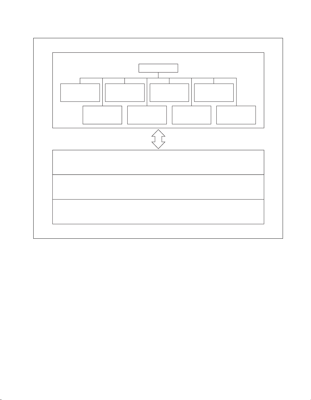
Software Programming Choices
Using NI-IMAQ, the National Instruments image acquisition driver
software, you can program your IMAQ board to acquire and save images.
You can use NI-IMAQ with other National Instruments software for a
complete image acquisition and analysis solution, as shown in Figure 1.
NI-IMAQ works with LabVIEW, BridgeVIEW, LabWindows/CVI, as
well as conventional programming languages. National Instruments
IMAQ Vision adds powerful image processing and analysis to these
programming environments. You can also use IMAQ Vision Builder to
quickly and easily prototype your IMAQ image analysis applications.
IMAQ PCI/PXI-1411 User Manual 1-2 www.ni.com
Page 11
Vision Software
IMAQ Vision
Chapter 1 Introduction
Image
Analysis
Filters
Blob
Analysis
BridgeVIEWLabVIEW
Pattern
Matching
Color Matching
and Analysis
Application Software
(ComponentWorks)
Driver Software
NI-DAQNI-IMAQ
Hardware
DAQIMAQ
Gauging and
Measurement
Display
and ROI
LabWindows/CVIActiveX
ValueMotion/
FlexMotion
ValueMotion/
FlexMotion
Morphology
Figure 1-1. The Relationship between the Programming Environment,
NI-IMAQ, and Your Hardware
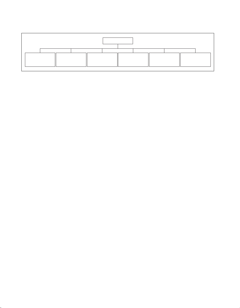
NI-IMAQ Driver Software
The NI-IMAQ driver software is included with your IMAQ device.
NI-IMAQ has an extensive library of functions that you can call from your
application programming environment. These functions include routines
for video configuration, image acquisition (continuous and single-shot),
memory buffer allocation, trigger control, and board configuration, as
shown in Figure 1-2.
© National Instruments Corporation 1-3 IMAQ PCI/PXI-1411 User Manual
Page 12
Chapter 1 Introduction
NI-IMAQ
Acquisition
T riggering
and Timing
DAQ
Synchronization
Buffer ControlImage
Figure 1-2. NI-IMAQ Functions
Camera Control Look-up T ab le
The NI-IMAQ dri ver software performs all functions required for acquiring
and saving images. The NI-IMAQ software does not perform any image
analysis. For image analysis functionality , refer to the National Instruments
IMAQ Vision section in this chapter.
NI-IMAQ has both high-level and low-level functions for maximum
flexibility and performance. Examples of high-level functions include the
functions to acquire images in single-shot or continuous mode. An example
of a low-level function is configuring an image sequence since it requires
advanced understanding of your IMAQ device and image acquisition.
NI-IMAQ internally resolves many of the complex issues between the
computer and your IMAQ device, such as programming interrupts and
DMA controllers.
NI-IMAQ is also the interface path between LabVIEW, BridgeVIEW,
LabWindows/CVI, or a conventional programming environment and your
IMAQ device. The NI-IMAQ software kit includes a series of libraries for
G, LabWindows/CVI, and ComponentWorks (ActiveX) that are
functionally equivalent to the NI-IMAQ software.
Control
IMAQ PCI/PXI-1411 User Manual 1-4 www.ni.com
Page 13
National Instruments IMAQ Vision
IMAQ Vision is an image acquisition, processing, and analysis library of
more than 200 functions for grayscale, color, and binary image display,
image processing, pattern matching, shape matching, blob analysis,
gauging, and measurement.
You can use IMAQ Vision functions directly or in combination for unique
image processing. With IMA Q V ision you can acquire, display, manipulate,
and store images as well as perform image analysis, processing, and
interpretation. Using IMAQ Vision, an imaging novice or expert can
perform graphical programming of the most basic or complicated image
applications without knowledge of any algorithm implementations.
IMAQ V ision is a vailable for LabVIEW, BridgeVIEW, LabWindows /CVI,
Microsoft Visual C++, or ComponentWorks.
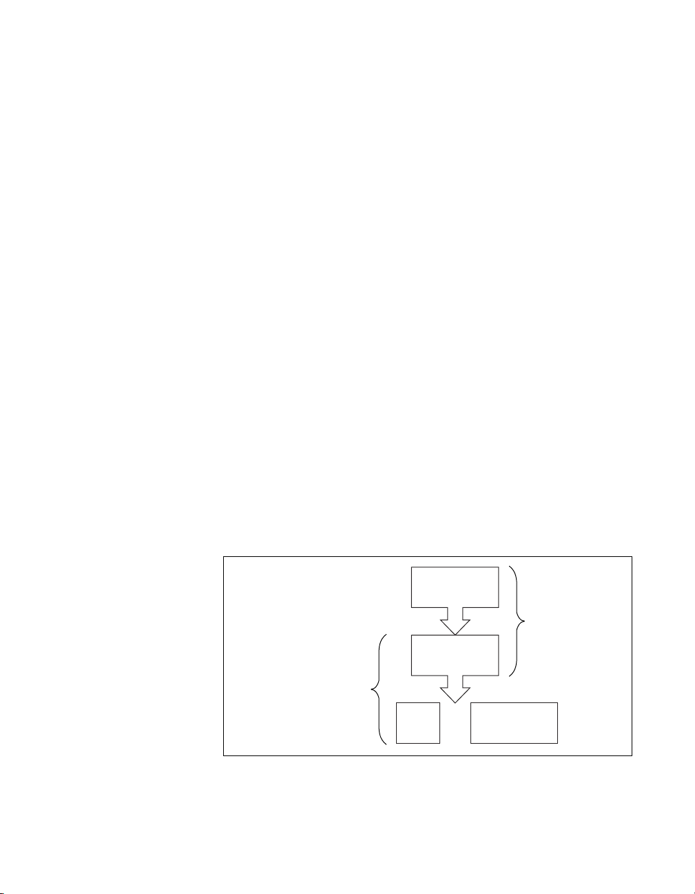
IMAQ Vision Builder
IMAQ Vision Builder is an interactive prototyping tool for machine vision
and scientific imaging developers. With IMAQ Vision Builder, you can
prototype vision software quickly or test how various vision image
processing functions work.
Chapter 1 Introduction
As shown in Figure 1-3, IMAQ Vision Builder generates a Builder file,
which is a text description that contains a recipe of the machine vision and
image processing functions. This Builder file provides a guide you can use
to develop applications with IMAQ Vision in LabVIEW, BridgeVIEW,
LabWindows/CVI, and ComponentWorks.
IMAQ
Vision Builder
Prototype
Builder File
Vision Application
Development
IMAQ
Vision
Figure 1-3.
© National Instruments Corporation 1-5 IMAQ PCI/PXI-1411 User Manual
IMAQ Vision Builder and Application Development Tools
and
Application
Software
Page 14

Chapter 1 Introduction
Integration with DAQ
Any platform that supports NI-IMAQ also supports NI-DAQ and a variety
of National Instruments DAQ boards, so your IMAQ device and NI-IMAQ
development can integrate with National Instruments DAQ products.
Vision and Motion
With National Instruments IMAQ hardware and IMAQ Vision pattern
matching software you can quickly and accurately locate objects in
instances where objects vary in size, orientation, focus, and even when the
part is poorly illuminated. Use National Instruments high-performance
stepper and servo motion control products with pattern matching software
in inspection and guidance applications such as locating alignment markers
on semiconductor wafers, guiding robotic arms, inspecting the quality of
manufactured parts, and locating cells.
IMAQ PCI/PXI-1411 User Manual 1-6 www.ni.com
Page 15

Installation
This chapter lists what you need to get started acquiring images with
your IMAQ device; describes optional equipment and custom cables;
and explains how to unpack, configure, and install your IMAQ device.
What You Need to Get Started
To set up and use your PCI/PXI-1411, you will need the following:
❑ One of the following IMAQ devices:
– PCI-1411
– PXI-1411
❑ Getting Started with Your IMAQ System
❑ IMAQ PCI/PXI-1411 User Manual
❑ NI-IMAQ release notes
2
❑ NI-IMAQ for Windows 2000/NT/9x and documentation
❑ Optional software packages and documentation:
– IMAQ Vision for G, LabWindows/CVI, or ComponentWorks
–LabVIEW
– BridgeVIEW
– LabWindows/CVI
– IMAQ Vision Builder
❑ BNC cable (included with your PCI/PXI-1411)
❑ S-Video cable (optional)
❑ Your Pentium-based PCI computer, PXI chassis, or CompactPCI
chassis running Windows 2000, Windows NT, or Windows 9x
❑ An analog video camera (composite or S-Video)
© National Instruments Corporation 2-1 IMAQ PCI/PXI-1411 User Manual
Page 16

Chapter 2 Installation
Optional Equipment
National Instruments offers a variety of products for use with your
PCI/PXI-1411, including other National Instruments DAQ devices
for enhanced triggering, timing, or input/output.
For more specific information about these products, refer to your
National Instruments catalogue or Web site, or call the office nearest you.
How to Set up Your IMAQ System
Use Figure 2-1 as a guide while you install your software and hardware,
configure your hardware, and begin using NI-IMAQ in your application
programs.
Follow the instructions in the Getting Started with Your IMAQ System
document to install your NI-IMAQ software and IMAQ hardware.
If you will be accessing the NI-IMAQ device drivers through LabVIEW
or BridgeVIEW, you should read the NI-IMAQ release notes and the
NI-IMAQ VI Reference Manual to help you get started.
IMAQ PCI/PXI-1411 User Manual 2-2 www.ni.com
Page 17

Chapter 2 Installation
LabWindows/CVI
Third-Party Compilers
Read Chapter 1,
to NI-IMAQ
Introduction
, in the
NI-IMAQ User Manual
Read the sections in
chapters 2 and 3 in the
User Manual
will use in your application.
Look at the self-documented
example source code on your
distribution CD for your
application language
that apply to the
function groups you
and environment.
NI-IMAQ
Read the
document and the NI-IMAQ release notes to install
Getting Started with Your IMAQ System
your NI-IMAQ software, IMAQ hardware,
Measurement & Automation Explorer and
and documentation.
Configure your hardware using the
online help.
What
application software
are you using?
ComponentWorks
Getting Results with
Read
BridgeVIEW
ComponentWorks IMAQ Vision
.
for information on using
ComponentWorks in your
application environment.
Use the ComponentWorks
IMAQ Vision documentation
when you need specific
information about individual
NI-IMAQ functions.
LabVIEW
Read:
•
NI-IMAQ VI Reference
Manual
• Your IMAQ Vision for G
documentation if you are
using IMAQ Vision for G
You no longer need the online
NI-IMAQ documentation.
Use the
Reference Manual
need specific information about
individual NI-IMAQ functions.
If you are using IMAQ Vision for
LabWindows/CVI, read the
documentation for IMAQ Vision
NI-IMAQ Function
when you
for LabWindows/CVI.
Figure 2-1. How to Set up Your IMAQ System
© National Instruments Corporation 2-3 IMAQ PCI/PXI-1411 User Manual
Page 18

Chapter 2 Installation
Unpacking
Installation
Note
You must install the NI-IMAQ driver software before installing your 1411 device.
For information on how to install NI-IMAQ, please see the Getting Started with Your
IMAQ System document and your NI-IMAQ release notes.
Your PCI/PXI-1411 is shipped in an antistatic package to prevent
electrostatic damage to the board. Electrostatic discharge can damage
several components on the board. To avoid such damage in handling the
board, take the following precautions:
• Ground yourself via a grounding strap or b y holding a grounded object.
• Touch the antistatic package to a metal part of your computer chassis
before removing the board from the package.
• Remove the board from the package and inspect the board for loose
components or any other signs of damage. Notify National Instruments
if the board appears damaged in any way. Do not install a damaged
board in your computer.
• Never touch the exposed pins of connectors.
♦ PCI-1411
You can install the PCI-1411 in any available PCI expansion slot in your
computer. However, to achieve the best noise performance, you should
leave as much room as possible between the PCI-1411 and other boards and
hardware. The following are general instructions, but consult your
computer user manual or technical reference manual for specific
instructions and warnings.
1. Plug in but do not turn on your computer before installing the
PCI-1411 device. The power cord grounds the computer and protects
it from electrical damage while you are installing the module.
Warning
should remain off until you finish installing the PCI-1411.
IMAQ PCI/PXI-1411 User Manual 2-4 www.ni.com
T o protect both yourself and the computer from electrical hazards, the computer
2. Remove the top cover or access port to the PCI bus.
3. Select any available PCI expansion slot.
Page 19

Chapter 2 Installation
4. Locate the metal bracket that covers the cut-out in the back panel
of the chassis for the slot you have selected. Remove and save the
bracket-retaining screw and the bracket cover.
5. Touch the metal part of the power supply case inside the computer to
discharge any static electricity that might be on your clothes or body.
6. Line up the PCI-1411 with the BNC connectors near the cut-out on the
back panel. Slowly push down on the top of the PCI-1411 until its
card-edge connector is resting on the expansion slot receptacle. Using
slow, evenly distributed pressure, press the PCI-1411 straight down
until it seats in the expansion slot.
7. Reinstall the bracket-retaining screw to secure the PCI-1411 to the
back panel rail.
8. Visually verify the installation.
9. Replace the computer cover.
Your PCI-1411 is now installed.
♦ PXI-1411
You can install a PXI-1411 in any available 5 V peripheral slot in your
PXI or CompactPCI chassis.
1. Turn off and unplug your PXI or CompactPCI chassis.
2. Choose an unused PXI or CompactPCI 5 V peripheral slot. Install the
PXI-1411 in a slot that supports bus arbitration or bus-master cards.
PXI-compliant chassis must have bus arbitration for all slots.
3. Remove the filler panel for the peripheral slot you have chosen.
4. Touch a metal part on your chassis to discharge any static electricity
that might be on your clothes or body.
5. Insert the PXI-1411 in the selected 5 V slot. Use the injector/ejector
handle to fully inject the device into place.
6. Screw the front panel of the PXI-1411 to the front panel mounting rails
of the PXI or CompactPCI chassis.
7. Visually verify the installation.
8. Plug in and turn on the PXI or CompactPCI chassis.
Your PXI-1411 is now installed.
© National Instruments Corporation 2-5 IMAQ PCI/PXI-1411 User Manual
Page 20

Hardware Overview
This chapter presents an overview of the hardware functions on your
PCI/PXI-1411 board and explains the operation of each functional unit
making up the PCI/PXI-1411.
Functional Overview
The PCI/PXI-1411 features a flexible, high-speed data path optimized for
the acquisition and formatting of video data from analog monochrome and
color cameras.
The block diagram in Figure 3-1 illustrates the key functional components
of the PCI/PXI-1411.
3
SDRAM
IMAQ SDRAM
Memory
Interface
PCI/PXI-1411 Block Diagram
PCI Interface
and
Scatter-Gather
DMA Controller
PCI Bus
Analog Video
(BNC or S-Video)
Video
Decoder
External Trigger
LUT
Color Space
Processor
Acquisition, ROI,
and Control
Figure 3-1.
Video Acquisition
The PCI/PXI-1411 can acquire analog color video in a variety of modes
and store the images in the onboard SDRAM memory or transfer the
images directly to PCI system memory.
© National Instruments Corporation 3-1 IMAQ PCI/PXI-1411 User Manual
Page 21

Chapter 3 Hardware Overview
Video Decoder
The PCI/PXI-1411 supports NTSC and PAL video standards in either
composite or S-Video format. The onboard video decoder converts the
incoming video signal to Red, Green, and Blue (RGB) data and passes
this data to the color-space processor for further processing.
The video decoder also allows you to control numerous parameters to
optimize an acquisition. You can independently adjust parameters such
as analog input range, brightness, contrast, saturation, or frequency range
(controlled by different filters). See the Measurement & Automation
Explorer online help for a complete description of the PCI/PXI-1411
video parameters.
Furthermore, the video decoder strips out all necessary clock and
synchronization signals included in the video signal and controls the
acquisition conditions automatically. High-quality circuitry regenerates
even bad timing signals allowing acquisitions from, for example, a video
cassette recorder (VCR).
Color-Space Processor and LUTs
The color-space processor receives the RGB data from the video decoder
and performs several different (optional) operations on the data before
passing them to the memory controller. Processing functions include the
following:
• Adjusting independent gain of the three signals (R, G, and B). You can
use independent gain to perform, for example, white balancing on the
acquired image.
• Applying three independent look-up tables (LUTs) to the R, G, and
B data.
• Con v erting the RGB data into Hue, Saturation, and Luminance (HSL).
• Processing the hue plane to clear pixels where the saturation
falls below a predefined threshold value. This function is called
post-decoding coring. You can use this function to remove part
of the image w ithout color information (monochrome) that
otherwise would introduce noise on the hue plane.
The color-space processor can export the video data in 32-bit RGB or HSL
formats or in individual 8-bit hue, saturation, or luminance planes. For
more information on these image types, see the Image Representations
section in Appendix B, Introduction to Color.
IMAQ PCI/PXI-1411 User Manual 3-2 www.ni.com
Page 22

SDRAM
The PCI/PXI-1411 comes with 16 MB of onboard high-speed synchronous
dynamic RAM (SDRAM). The PCI/PXI-1411 can use the onboard RAM
as a first-in first-out (FIFO) buffer, transferring the image data as it is
acquired or acquiring the image data into SDRAM and holding it for later
transfer to main memory.
Trigger Control and Mapping Circuitry
The trigger control monitors and drives the external trigger line. You can
configure this line to start an acquisition on a rising or falling edge and
drive the line asserted or unasserted, similar to a digital I/O line. You can
also map many of the PCI/PXI-1411 status signals to this trigger line and
program the trigger line in polarity and direction. For a list of mappable
status signals, see Chapter 3, Programming with NI-IMAQ, of the
NI-IMAQ User Manual.
Acquisition, Scaling, ROI
The acquisition, scaling, and region-of-interest (ROI) circuitry monitors
the incoming video signals and routes the active pixels to the SDRAM
memory. The PCI/PXI-1411 can perform ROI and scaling on all video lines
and frames. Pixel and line scaling transfers certain multiples (two, four, or
eight) of pixels and lines to onboard memory. In an ROI acquisition, you
select an area within the acquisition window to transfer to the PCI bus.
Chapter 3 Hardware Overview
Scatter-Gather DMA Controllers
The PCI/PXI-1411 uses three independent onboard direct memory
access (DMA) controllers. The DMA controllers transfer data between
the onboard SDRAM memory buffers and the PCI bus. Each of these
controllers supports scatter-gather DMA, which allows the DMA controller
to reconfigure on-the-fly. Thus, the PCI/PXI-1411 can perform continuous
image transfers directly to either contiguous or fragmented memory
buffers.
© National Instruments Corporation 3-3 IMAQ PCI/PXI-1411 User Manual
Page 23

Chapter 3 Hardware Overview
Bus Master PCI Interface
The PCI/PXI-1411 implements the PCI interface with a National
Instruments custom application-specific integrated circuit (ASIC), the
PCI MITE. The PCI interface can transfer data at a maximum rate of
132 Mbytes/s in bus master mode. The PCI/PXI-1411 can generate 8-, 16-,
and 32-bit memory read and write cycles, both single and multiple. In slave
mode, the PCI/PXI-1411 is a medium-speed decoder that accepts both
memory and configuration cycles. The interface logic ensures that the
PCI/PXI-1411 can meet PCI loading, driving, and timing requirements.
Board Configuration NVRAM
The PCI/PXI-1411 contains onboard nonvolatile RAM (NVRAM) that
configures all registers on power-up.
Start Conditions
The PCI/PXI-1411 can start acquisitions in a variety of conditions:
• Software control—The PCI/PXI-1411 supports software control of
acquisition start. You can configure the PCI/PXI-1411 to capture a
fixed number of fields or frames. This configuration is useful for
capturing a single frame or a sequence of frames.
• Trigger control—Y ou can start an acquisition by enabling the e xternal
trigger line. This input can start a video acquisition on a rising or
falling edge.
• Frame/field selection—With an interlaced camera and the
PCI/PXI-1411 in frame mode, you can program the PCI/PXI-1411
to start an acquisition on any odd or even field.
Acquisition Window Control
You can configure numerous parameters on the PCI/PXI-1411 to control
the video acquisition window. A brief description of each parameter
follows:
• Acquisition windo w—The PCI/PXI-1411 allows the user to specify a
particular region of active pixels and active lines within the incoming
video data. The active pixel region selects the starting pixel and
number of pixels to be acquired relative to the assertion edge of the
horizontal (or line) enable signal from the camera. The active line
region selects the starting line and number of lines to be acquired
relative to the assertion edge of the vertical (or frame) enable signal.
IMAQ PCI/PXI-1411 User Manual 3-4 www.ni.com
Page 24

Chapter 3 Hardware Overview
• Region of interest—The PCI/PXI-1411 uses a second level of active
pixel and active line regions for selecting a region of interest. When
you disable the region-of-interest circuitry, the board stores the entire
acquisition window into with onboard or system memory. However,
when you enable the region-of-interest circuitry, the board acquires
only a selected subset of the image frame.
• Scaling down—The scaling down circuitry also controls the active
acquisition region. The PCI/PXI-1411 can scale down a frame by
reducing the number of pixels per line, the number of lines per frame,
or both. For active pixel selection, the PCI/PXI-1411 can select every
pixel, every other pixel, every fourth pixel, or ev ery eighth pixel. For
active line selection, the PCI/PXI-1411 can select every line, every
other line, every fourth line, or every eighth line. You can use the
scaling down circuitry in conjunction with the region-of-interest
circuitry.
© National Instruments Corporation 3-5 IMAQ PCI/PXI-1411 User Manual
Page 25

Signal Connections
This chapter describes cable connections for the PCI/PXI-1411.
I/O Connector
The PCI/PXI-1411 uses one S-Video and two BNC connectors on the
front panel to connect to video data inputs and the external trigger signal.
Figure 4-1 shows the position of the three connectors.
4
VIDEO
S-VIDEO
TRIG
Figure 4-1.
© National Instruments Corporation 4-1 IMAQ PCI/PXI-1411 User Manual
PCI/PXI-1411 Connectors
Page 26

Chapter 4 Signal Connections
Signal Description
Table 4-1 describes each signal connection on the 1411 device connectors:
Table 4-1.
Signal Name Description
VIDEO Composite Video—The signal allo ws you to make a referenced single-ended
(RSE) connection to the video channel.
S-VIDEO S-Video—A connector composed of two signals, as follows:
Y—The Y signal of the S-Video connection contains the luma and
synchronization information of the video signal.
C—The C signal of the S-Video connection contains the chroma
information of the video signal.
TRIG External trigger—A TTL I/O line you can use to start an acquisition or to
control external events. You can program the triggers to be rising or falling
edge sensitive. You can also program the triggers to be programmatically
asserted or unasserted similar to the function of a digital I/O line or to contain
internal status signals (by using the onboard events). For a list of mappable
status signals, see Chapter 3, Programming with NI-IMAQ, of the
NI-IMAQ User Manual.
GND Ground—A direct connection to digital ground on the PCI/PXI-1411.
I/O Connector Signals
Custom Cables
If you plan to make your own cables, refer to Figure 4-2 for the pin-out of
the S-Video connector, as seen from the front of the PCI/PXI-1411.
GND
GND
Figure 4-2.
IMAQ PCI/PXI-1411 User Manual 4-2 www.ni.com
S-Video Connector Pin Assignments
C
Y
Page 27

Specifications
This appendix lists the specifications of the PCI/PXI-1411. These
specifications are typical at 25 °C, unless otherwise stated.
Formats Supported
Input formats
RS-170/NTSC.................................29.97 frames/s
CCIR/PAL ......................................25 frames/s
Output formats
RGB ............................................... 32-bit
HSL................................................. 32-bit
R, G, B, H, S, or L ..........................8-bit
Pixel aspect ratio.............................Square pixel
Video Input
Quantity..................................................1 (VIDEO)
A
VIDEO.................................................. .Composite video on BNC (RSE),
Y/C on S-Video connector (RSE)
Input impedance.....................................75 Ω
Input range (blank to white)................... 700 mV (calibrated) or
400 mV to 1.00 V (variable gain)
Frequency response (luminance)
Full range........................................12 MHz (–3 dB) typ
(all filters off)
Programmable.................................Decimation and lowpass filters
© National Instruments Corporation A-1 IMAQ PCI/PXI-1411 User Manual
Page 28

Appendix A Specifications
A/D Conversion
Color Decoding
Quantity ..................................................One 8-bit 2X oversampling
for composite video
Two 8-bit 2X oversampling
for Y/C (S-Video)
Dynamic range........................................46 dB typ
Sampling Frequency
RS-170/NTSC..................................27.54 MHz (double rate
of square pixel
CCIR/PAL.......................................29.5 MHz (double rate
of square pixel)
Composite video
Luma path........................................Chroma trap filter and/or
line comb
Chroma path ....................................Bandpass filter and/or line comb
Accuracy
Calibrated
Luma level at DC.............................+/– (1% of value and 1% of white)
(tentative)
Demodulated chroma level at DC ...+/– 2% (tentative)
Memory
Onboard memory....................................16 MB synchronous
dynamic RAM
LUTs.......................................................Three 256 × 8 (RGB only)
External Connections
Trigger sense...........................................TTL
Trigger level ...........................................Programmable (rising or falling)
IMAQ PCI/PXI-1411 User Manual A-2 www.ni.com
Page 29

PCI Interface
Appendix A Specifications
PCI initiator (master) capability............. Supported
PCI target (slave) capability...................Supported
Data path................................................32 bits
Board voltage.........................................5 V, 12 V, –12 V
Board type..............................................32-bit half-size card
Parity generation/checking,
error reporting ........................................ Supported
Target decode speed...............................Medium (1 clock)
Target fast back-to-back capability........ Supported
Resource locking....................................Supported as a master and slave
PCI interrupts.........................................Interrupts passed on
INTA# signal
Base address registers ............................BAR0 (16 KB)
BAR1 (64 KB)
Expansion ROM.....................................4 KB
PCI master performance
Ideal ................................................133 Mbytes/s
Sustained.........................................100 Mbytes/s
Power Requirements
Voltage...................................................+ 5 V (1.00 A)
+12 V (75 mA)
© National Instruments Corporation A-3 IMAQ PCI/PXI-1411 User Manual
Page 30

Appendix A Specifications
Physical
Environment
Dimensions
PCI-1411..........................................10.7 by 17.5 cm
(4.2 by 6.9 in.)
PXI-1411 .........................................10 by 16 cm
(3.9 by 6.3 in.)
Weight
PCI-1411..........................................0.136 kg (0.3 lb.)
PXI-1411 .........................................0.154 kg (0.34 lb.)
Operating temperature............................ 0–55 °C
Storage temperature................................–20–70 °C
Relative humidity ...................................5–90%, noncondensing
MTBF .....................................................839,653 h at 30 °C
Emissions................................. ...... ... ..... .EN 55011:1991 Group 1 Class A
at 10 m FCC Class A at 10 m
Functional shock (PXI only)...................MIL-T-28800 E Class 3 (per
Section 4.5.5.4.1) Half-si ne shock
pulse, 11 ms duration, 30 g peak,
30 shocks per face
Operational random vibration
(PXI only)...............................................5 to 500 Hz, 0.31 grms, 3 axes
Nonoperational random vibration
(PXI only)...............................................5 to 500 Hz, 2.5 grms, 3 axes
Note
Random vibration profiles were developed in accordance with MIL-T-28800E and
MIL-STD-810E Method 514. Test levels exceed those recommended in MIL-STD-810E
for Category 1 (Basic Transportation, Figures 514.4-1 through 514.4-3).
IMAQ PCI/PXI-1411 User Manual A-4 www.ni.com
Page 31

Introduction to Color
Color is the wavelength of the light we receive in our eye when we look at
an object. In theory, the color spectrum is infinite. Humans, however, can
see only a small portion of this spectrum—the portion that goes from the
red edge of infrared light (the longest wavelength) to the blue edge of
ultraviolet light (the shortest wavelength). This continuous spectrum is
called the visible spectrum, as shown in Figure B-1.
B
Figure B-1.
White light is a combination of all colors at once. The spectrum of white
light is continuous and goes from ultraviolet to infrared in a smooth
transition. You can represent a good approximation of white light by
selecting a few reference colors and weighting them appropriately. The
most common way to represent white light is to use three reference
components, such as red, green, and blue (R, G, and B primaries). You can
simulate most colors of the visible spectrum using these primaries. For
example, video projectors use red, green, and blue light generators, and an
RGB camera uses red, green, and blue sensors.
© National Instruments Corporation B-1 IMAQ PCI/PXI-1411 User Manual
White Light and the Visible Spectrum
Page 32

Appendix B Introduction to Color
The perception of a color depends on many factors, such as:
• Hue, which is the perceived dominant color. Hue depends directly on
the wavelength of a color.
• Saturation, which is dependent on the amount of white light present in
a color. Pastels typically have a low saturation while very rich colors
have a high saturation. For example, pink typically has a red hue but
has a low saturation.
• Luminance, which is the brightness information in the video picture.
The luminance signal amplitude varies in proportion to the brightness
of the video signal and corresponds exactly to the monochrome
picture.
• Intensity, which is the brightness of a color and which is usually
expressed as light or dark. For example, orange and brown may have
the same hue and saturation; however, orange has a greater intensity
than brown.
Image Representations
Color images can be represented in several different formats. These formats
can contain all color information from the image or they can consist of just
one aspect of the color information, such as hue or luminance. The
following image representations can be produced using the PCI/PXI-1411.
RGB
The most common image representation is 32-bit RGB format. In this
representation, the three 8-bit color planes—red, green and blue—are
packed into an array of 32-bit integers. This representation is useful for
displaying the image on your monitor. The 32-bit integer organized as:
0 RED GREEN BLUE
where the high-order byte is not used and blue is the low-order byte.
Color Planes
Each color plane can be returned individually . The red, green, or blue plane
is extracted from the RGB image and represented as an array of 8-bit
integers.
IMAQ PCI/PXI-1411 User Manual B-2 www.ni.com
Page 33

Hue, Saturation, Luminance, and Intensity Planes
The 8-bit hue, saturation, luminance, and intensity planes can also be
returned individually if you want to analyze the image.
Luminance, Intensity , Hue, or Saturation are defined using the Red, Green,
and Blue values in the following formulas:
Luminance = 0.299 × Red + 0.587 × Green + 0.114 × Blue
Intensity = (Red + Green + Blue) / 3
Hue = ATN2 (Y, X)
where
Y = (Green - Blue) / and
X = (2 × Red - Green - Blue) /
Saturation =
×
255 1
2
6
3 Min R G B,,()×
----------------------------------------- -–
RGB++
32-Bit HSL and HSI
You can also pack the three 8-bit Hue, Saturation, and Luminance planes
(HSL) or the three Hue, Saturation, and Intensity planes (HSI) in one array
of 32-bit integers, which is equivalent to the 32-bit RGB representation.
Appendix B Introduction to Color
© National Instruments Corporation B-3 IMAQ PCI/PXI-1411 User Manual
Page 34

Technical Support Resources
This appendix describes the comprehensive resources available to yo u in
the Technical Support section of the National Instruments Web site and
provides technical support telephone numbers for you to use if you have
trouble connecting to our Web site or if you do not have internet access.
NI Web Support
To provide you with immediate answers and solutions 24 hours a day,
365 days a year, National Instruments maintains extensi ve online technical
support resources. They are available to you at no cost, are updated daily,
and can be found in the Technical Support section of our Web site at
www.ni.com/support
Online Problem-Solving and Diagnostic Resources
• KnowledgeBase—A searchable database containing thousands of
frequently asked questions (F A Qs) and their corresponding answers or
solutions, including special sections devoted to our newest products.
The database is updated daily in response to new customer experiences
and feedback.
• Troubleshooting Wizards—Step-by-step guides lead you through
common problems and answer questions about our entire product line.
Wizards include screen shots that illustrate the steps being described
and provide detailed information ranging from simple getting started
instructions to advanced topics.
• Product Manuals—A comprehensive, searchable library of the latest
editions of National Instruments hardware and software product
manuals.
• Hardware Reference Database—A searchable database containing
brief hardware descriptions, mechanical drawings, and helpful images
of jumper settings and connector pinouts.
• Application Notes—A library with more than 100 short papers
addressing specific topics such as creating and calling DLLs,
developing your own instrument driver software, and porting
applications between platforms and operating systems.
C
© National Instruments Corporation C-1 IMAQ PCI/PXI-1411 User Manual
Page 35

Appendix C Technical Support Resources
Software-Related Resources
• Instrument Driver Network—A library with hundreds of instrument
drivers for control of standalone instruments via GPIB, VXI, or serial
interfaces. You also can submit a request for a particular instrument
driver if it does not already appear in the library.
• Example Programs Database—A database with numerous,
non-shipping example programs for National Instruments
programming environments. You can use them to complement the
example programs that are already included with National Instruments
products.
• Software Library—A library with updates and patches to application
software, links to the latest versions of driver software for National
Instruments hardware products, and utility routines.
Worldwide Support
National Instruments has offices located around the globe. Many branch
offices maintain a Web site to provide information on local services. You
can access these Web sites from
www.ni.com/worldwide
If you have trouble connecting to our Web site, please contact your local
National Instruments office or the source from which you purchased your
National Instruments product(s) to obtain support.
For telephone support in the United States, dial 512 795 8248. For
telephone support outside the United States, contact your local branch
office:
Australia 03 9879 5166, Austria 0662 45 79 90 0, Belgium 02 757 00 20,
Brazil 011 284 5011, Canada (Calgary) 403 274 9391 ,
Canada (Ontario) 905 785 0085, Canada (Québec) 514 694 8521,
China 0755 3904939, Denmark 45 76 26 00, Finland 09 725 725 11,
France 01 48 14 24 24, Germany 089 741 31 30, Greece 30 1 42 96 427,
Hong Kong 2645 3186, India 91805275406, Israel 03 6120092,
Italy 02 41309 1, Japan 03 5472 2970, Korea 02 596 7456,
Mexico (D.F.) 5 280 7625, Mexico (Monterrey) 8 357 7695,
Netherlands 0348 433466, Norway 32 27 73 00, Poland 48 22 528 94 06,
Portugal 351 1 726 9011, Singapore 2265886, Spain 91 640 0085,
Sweden 08 58 7 895 00, Switzerland 056 200 51 51,
Taiwan 02 2377 1200, United Kingdom 01635 523545
IMAQ PCI/PXI-1411 User Manual C-2 www.ni.com
Page 36

Glossary
Prefix Meaning Value
p- pico- 10
n- nano- 10
µ- micro- 10
m- milli- 10
k- kilo- 10
M- mega- 10
G- giga- 10
t- tera- 10
Numbers/Symbols
+ Positive of, or plus.
–12
–9
–6
–3
3
6
9
12
/Per.
Ω Ohm.
± Plus or minus.
– Negative of, or minus.
A
A Amperes.
AC Alternating current.
acquisition window The image size specific to a video standard or camera resolution.
active line region The region of lines actively being stored. Defi ned by a line start (relati ve to
the vertical synchronization signal) and a line count.
© National Instruments Corporation G-1 IMAQ PCI/PXI-1411 User Manual
Page 37

Glossary
active pixel region The region of pixels actively being stored. Def ined by a pixel start (relati ve
to the horizontal synchronization signal) and a pixel count.
address Value that identifies a specific location (or series of locations) in memory.
API Application programming interface.
area A rectangular portion of an acquisition window or frame that is controlled
and defined by software.
array Ordered, indexed set of data elements of the same type.
ASIC Application-Specific Integrated Circuit. A proprietary semiconductor
component designed and manufactured to perform a set of specific
functions for specific customer needs.
B
b Bit. One binary digit, either 0 or 1.
B Byte. Eight related bits of data, an eight-bit binary number; also used to
denote the amount of memory required to store one byte of data
brightn ess A constant that is added to the red, green, and blue components of a color
pixel during the color decoding process.
buffer Temporary storage for acquired data.
bus A group of conductors that interconnect individual circuitry in a computer,
such as the PCI bus; typically the expansion vehicle to which I/O or other
devices are connected.
C
C Celsius.
cache High-speed processor memory that buffers commonly used instructions or
data to increase processing throughput.
CMOS Complementary metal-oxide semiconductor.
IMAQ PCI/PXI-1411 User Manual G-2 www.ni.com
Page 38

Glossary
color s pace The mathematical representation for a color. For example, color can be
described in terms of red, green, and blue; hue, saturation, and luma; or hue,
saturation, and intensity.
com posite video A type of color video transmission where synchronization, luma, and
chroma information are transmitted on one analog signal.
contrast A constant multiplication factor applied to the luma and chroma
components of a color pixel in the color decoding process.
coring The process of eliminating color information in low-color situations (if the
saturation is lower than a predefined value).
CPU Central processing unit.
D
DAQ Data acquisition. (1) Collecting and measuring electrical signals from
sensors, transducers, and test probes or fixtures and inputting them to a
computer for processing. (2) Collecting and measuring the same kinds of
electrical signals with A/D or DIO boards plugged into a computer, and
possibly generating control signals with D/A and/or DIO boards in the
same computer.
dB Decibel. The unit for expressing a logarithmic measure of the ratio of two
signal levels: dB = 20log
V1/V2, for signals in volts.
10
DC Direct current.
default setting A default parameter value recorded in the dri ver; in man y cases, the default
input of a control is a certain value (often 0) that means use the current
default setting.
DMA Direct memory access. A method by which data can be transferred to and
from computer memory from and to a device or memory on the bus while
the processor does something else; DMA is the fastest method of
transferring data to/from computer memory.
DRAM Dynamic RAM.
© National Instruments Corporation G-3 IMAQ PCI/PXI-1411 User Manual
Page 39

Glossary
drivers Software that controls a specific hardware device, such as an image
acquisition board.
dynamic range The ratio of the largest signal level a circuit can handle to the smallest
signal level it can handle (usually taken to be the noise level), normally
expressed in decibels.
E
EEPROM Electrically erasable programmable read-only memory. ROM that can be
erased with an electrical signal and reprogrammed.
externa l trigger A voltage pulse from an external source that triggers an event such as
A/D conversion.
F
field For an interlaced video signal, a field is half the number of horizontal
lines needed to represent a frame of video. The first field of a frame
contains all the odd-numbered lines, the second field contains all of the
even-numbered lines.
FIFO First-in first-out memory buffer. The first data stored is the first data sent
to the acceptor; FIFOs are used on IMAQ devices to temporarily store
incoming data until that data can be retrieved.
frame A complete image. In interlaced formats, a frame is composed of two fields.
ft Feet.
G
gamma The nonlinear change in the difference between the video signal’s
brightness level and the voltage level needed to produce that brightness.
genlock Circuitry that aligns the video timing signals by locking together the
horizontal, vertical, and color subcarrier frequencies and phases and
generates a pixel clock to clock pixel data into memory for display or into
another circuit for processing.
IMAQ PCI/PXI-1411 User Manual G-4 www.ni.com
Page 40

Glossary
H
hHour.
HSI Color encoding scheme in Hue, Saturation, and Intensity.
HSL Color encoding scheme using Hue, Saturation, and Luma information
where each image in the pixel is encoded using 32 bits: 8 bits for hue, 8 bits
for saturation, 8 bits for luma, and 8 unused bits.
HSYNC Horizontal synchronization signal. The synchronization pulse signal
produced at the beginning of each video scan line that keeps a video
monitor’s horizontal scan rate in step with the transmission of each
new line.
hue Represents the dominant color of a pixel. The hue function is a continuous
function that covers all the possible colors generated using the R, G, and
Bprimaries. See also RGB.
hue offset The value added to all hue values so that the discontinuity occurs outside
the values of interest during analysis.
Hz Hertz. Frequency in units of 1/second.
I
I/O Input/output. The tran sfer of da ta to/from a computer system involving
communications channels, operator interface devices, and/or data
acquisition and control interfaces.
IC Integrated circuit.
IEEE Institute of Electrical and Electronics Engineers.
IMAQ Image acquisition.
in. Inches.
instrument driver A set of high-level software functions, such as NI-IMAQ, that control
specific plug-in computer boards. Instrument drivers are available in
several forms, ranging from a function callable from a programming
language to a virtual instrument (VI) in LabVIEW.
© National Instruments Corporation G-5 IMAQ PCI/PXI-1411 User Manual
Page 41

Glossary
intensity The sum of the Red, Green, and Blue primaries divided by three:
(Red + Green + Blue)/3.
interlaced A video frame composed of two interleaved fields. The number of lines in
a field are half the number of lines in an interlaced frame.
interrupt A computer signal indicating that the CPU should suspend its current task
to service a designated activity.
interru pt level The relative priority at which a device can interrupt.
IRQ Interrupt request. See interrupt.
K
k Kilo. The standard metric prefix for 1,000, or 103, used with units of
measure such as volts, hertz, and meters.
K Kilo. The prefix for 1,024, or 2
10
, used with B in quantifying data or
computer memory.
kbytes/ s A unit for data transfer that means 1,000 or 10
3
bytes/s.
Kword 1,024 words of memory.
L
line co unt The total number of horizontal lines in the picture.
LSB Least significant bit.
luma The brightness information in the video picture. The luma signal amplitude
varies in proportion to the brightness of the video signal and corresponds
exactly to the monochrome picture.
luminance See luma.
LUT Look-up table. Table containing values used to transform the gray-level
values of an image. For each gray-le vel value in the image, the
corresponding new value is obtained from the look-up table.
IMAQ PCI/PXI-1411 User Manual G-6 www.ni.com
Page 42

M
m Meters.
Glossary
M (1) Mega, the standard metric prefix for 1 million or 10
6
, when used with
units of measure such as volts and hertz; (2) mega, the prefix for 1,048,576,
20
or 2
, when used with B to quantify data or computer memory.
MB Megabyte of memory.
Mbytes/s A unit for data transfer that means 1 million or 10
6
bytes/s.
memory buffer See buffer.
memory window Continuous blocks of memory that can be accessed quickly by changing
addresses on the local processor.
MSB Most significant bit.
MTBF Mean time between failure.
mux Mul tiplexer. A switch ing device with multiple inputs that selectively
connects one of its inputs to its output.
N
NI-IMAQ Driver software for National Instruments IMAQ hardware.
noninterlaced A video frame where all the lines are scanned sequentially, instead of
divided into two frames as in an interlaced video frame.
NTSC National Television Standards Committee. The commit tee that developed
the color video standard used primarily in North America, which uses
525 lines per frame. See also PAL.
NVRAM Non v olatile RAM. RAM that is not erased when a de vice loses po wer or is
turned off.
O
operating system Base-level software that controls a computer , runs programs, interacts with
users, and communicates with installed hardware or peripheral devices.
© National Instruments Corporation G-7 IMAQ PCI/PXI-1411 User Manual
Page 43

Glossary
P
PAL Phase Alternatio n Line. One of the European video color standards; uses
625 lines per frame. See also NTSC.
PCI Peripheral Component Interconnect. A high-performance expansion bus
architecture originally developed by Intel to replace ISA and EISA. PCI
offers a theoretical maximum transfer rate of 132 Mbytes/s.
pixel Picture element. The smallest division that makes up the video scan line;
for display on a computer monitor, a pixel’s optimum dimension is square
(aspect ratio of 1:1, or the width equal to the height).
pixel clock Divides the incoming horizontal video line into pixels.
pixel count The total number of pixels between two horizontal synchronization signals.
The pixel count determines the frequency of the pixel clock.
PLL Phase-locked loop. Circuitry that provides a very stable pixel clock that is
referenced to another signal, for example, an incoming horizontal
synchronization signal.
protocol The exact sequence of bits, characters, and control codes used to
transfer data between computers and peripherals through a
communications channel.
pts Points.
R
RAM Random-access memory.
real time A property of an event or system in which data is processed as it is acquired
instead of being accumulated and processed at a later time.
relative accuracy A measure in LSB of the accuracy of an ADC; it includes all nonlinearity
and quantization errors but does not include offset and gain errors of the
circuitry feeding the ADC.
resolution The smallest signal increment that can be detected by a measurement
system. Resolution can be expressed in bits, in proportions, or in
percent of full scale. For example, a system has 12-bit resolution, one
part in 4,096 resolution, and 0.0244 percent of full scale.
IMAQ PCI/PXI-1411 User Manual G-8 www.ni.com
Page 44

Glossary
RGB Color encoding scheme using red, green, and blue (RGB) color information
where each pixel in the color image is encoded using 32 bits: 8 bits for red,
8 bits for green, 8 bits for blue, and 8 bits for the alpha value (unused).
ROI Regio n of in ter es t. A hardware-programmable rectangular portion of the
acquisition window.
ROM Read-only memory.
RS-170 The U.S. standard used for black-and-white television.
RSE Referenced single-ended. All measurements are made with respect to a
common reference measurement system or a ground. Also called a
grounded measurement system.
S
s Seconds.
S-Vi deo A type of color video transmission where timing and luma information are
transmitted on one analog signal and chroma is transmitted on a separate
analog signal.
saturation The amount of white added to a pure color. Saturation relates to the richness
of a color. A saturation of zero corresponds to a pure color with no white
added. Pink is a red with low saturation.
scaling down circuitr y Circuitry that scales down the resolution of a video signal.
scatter-gather DMA A type of DMA that allows the DMA controller to reconfigure on-the-fly .
SDRAM Synchronous dynamic RAM.
SRAM Static RAM.
sync T ells the display where to put a video picture. The horizontal sync indicates
the picture’s left-to-right placement and the vertical sync indicates
top-to-bottom placement.
system RAM RAM installed on a personal computer and used by the operating system,
as contrasted with onboard RAM.
© National Instruments Corporation G-9 IMAQ PCI/PXI-1411 User Manual
Page 45

Glossary
T
transfe r rate The rate, measured in bytes/s, at which data is moved from source to
destination after software initialization and set up operations. The
maximum rate at which the hardware can operate.
trigger Any event that causes or starts some form of data capture.
trigger control and
mapping circuitry
TTL Transistor-transistor logic.
Circuitry that routes, monitors, and drives external and RTSI bus trigger
lines. You can configure each of these lines to start or stop acquisition on a
rising or falling edge.
V
VCO Voltage-controlled oscillator. An oscillator that changes frequency
depending on a control signal; used in a PLL to generate a stable
pixel clock.
VI Virtual Instrument. (1) A combination of hardware and/or software
elements, typically used with a PC, that has the functionality of a classic
stand-alone instrument (2) A LabVIEW software module (VI), which
consists of a front panel user interface and a block diagram program.
VSYNC Vertical synchronization signal. The synchronization pulse generated at the
beginning of each video field that tells the video monitor when to start a
new field.
IMAQ PCI/PXI-1411 User Manual G-10 www.ni.com
Page 46

Index
A
accuracy specifications, A-2
acquisition
acquisition, scaling, and ROI circuitry, 3-3
acquisition window control, 3-4 to 3-5
start conditions, 3-4
acquisition window, 3-4
A/D conversion specifications, A-2
B
block diagram of PCI/PXI-1411, 3-1
board configuration NVRAM, 3-4
bus master PCI interface, 3-4
C
cables, custom, 4-2
color decoding specifications, A-2
color overview, B-1 to B-3
definition of color, B-1
image representations, B-2 to B-3
32-bit HSL and HSI, B-3
color planes, B-2
hue, saturation, luminance, and
intensity planes, B-3
RGB, B-2
perception of color, B-2
visible spectrum (figure), B-1
color planes, B-2
color-space processor and LUTs, 3-2
CompactPCI, using with PXI, 1-2
configuration
acquisition window control, 3-4 to 3-5
board configuration NVRAM, 3-4
setting up your IMAQ system (figure), 2-3
connector for PCI/PXI-1411 (figure), 4-1
custom cables, 4-2
D
diagnostic resources, online, C-1
DMA controllers, scatter-gather, 3-3
E
environment specifications, A-4
equipment, optional, 2-2
external connection specifications, A-2
F
formats supported, A-1
functional overview, 3-1
G
GND signal (table), 4-2
H
hardware overview, 3-1 to 3-5
acquisition, scaling, ROI, 3-3
acquisition window control, 3-4 to 3-5
block diagram of PCI/PXI-1411, 3-1
board configuration NVRAM, 3-4
bus master PCI interface, 3-4
color-space processor and LUTs, 3-2
functional overview, 3-1
scatter-gather DMA controllers, 3-3
SDRAM, 3-3
start conditions, 3-4
trigger control and mapping circuitry, 3-3
© National Instruments Corporation I-1 IMAQ PCI/PXI-1411 User Manual
Page 47

Index
video acquisition, 3-1
video decoder, 3-2
hue
32-bit HSL and HSI, B-3
definition, B-2
hue, saturation, luminance, and intensity
planes, B-3
I
image representations, B-2 to B-3
32-bit HSL and HSI, B-3
color planes, B-2
hue, saturation, luminance, and intensity
planes, B-3
RGB, B-2
IMAQ Vision Builder software, 1-5
IMAQ Vision software, 1-5
installation
PCI-1411 procedure, 2-4 to 2-5
PXI-1411 procedure, 2-5
setting up your IMAQ system
(figure), 2-3
unpacking PCI/PXI-1411, 2-4
intensity
32-bit HSL and HSI, B-3
definition, B-2
hue, saturation, luminance, and intensity
planes, B-3
I/O connector (figure), 4-1
L
look-up-tables (LUTs), 3-2
luminance
32-bit HSL and HSI, B-3
definition, B-2
hue, saturation, luminance, and intensity
planes, B-3
LUTs (look-up-tables), 3-2
M
mapping circuitry and trigger control, 3-3
memory
board configuration NVRAM, 3-4
SDRAM, 3-3
specifications, A-2
N
National Instruments Web support, C-1 to C-2
NI-IMAQ driver software, 1-3 to 1-4
NTSC video standard, 3-2
NVRAM, 3-4
O
online problem-solving and diagnostic
resources, C-1
optional equipment for PCI/PXI-1411, 2-2
P
PAL video standard, 3-2
PCI interface, A-3
PCI/PXI-1411. See also hardware overview.
optional equipment, 2-2
overview, 1-1
requirements for getting started, 2-1
software programming choices, 1-2 to 1-6
IMAQ Vision Builder software, 1-5
IMAQ Vision software, 1-5
NI-IMAQ driver software, 1-3 to 1-4
unpacking, 2-4
using PXI with CompactPCI, 1-2
physical specifications, A-4
post-decoding coring, 3-2
power requirement specifications, A-3
problem-solving and diagnostic resources,
online, C-1
PXI, using with CompactPCI, 1-2
IMAQ PCI/PXI-1411 User Manual I-2 www.ni.com
Page 48

Index
R
RAM
board configuration NVRAM, 3-4
SDRAM, 3-3
region of interest
acquisition, scaling, and ROI
circuitry, 3-3
configuring, 3-5
requirements for getting started, 2-1
RGB image representation, B-2
S
saturation
32-bit HSL and HSI, B-3
definition, B-2
hue, saturation, luminance, and intensity
planes, B-3
scaling down circuitry, 3-5
scatter-gather DMA controllers, 3-3
SDRAM, 3-3
setting up your IMAQ system (figure), 2-3
signal connections, 4-1 to 4-2
custom cables, 4-2
I/O connector (figure), 4-1
signal description (table), 4-2
software programming choices, 1-2 to 1-6
IMAQ Vision Builder software, 1-5
IMAQ Vision software, 1-5
NI-IMAQ driver software, 1-3 to 1-4
software-related resources, C-2
specifications, A-1 to A-4
accuracy, A-2
A/D conversion, A-2
color decoding, A-2
environment, A-4
external connections, A-2
formats supported, A-1
memory, A-2
PCI interface, A-3
physical, A-4
power requirements, A-3
video input, A-1
start conditions, 3-4
S-VIDEO signal (table), 4-2
T
technical support resources, C-1 to C-2
TRIG signal (table), 4-2
trigger control and mapping circuitry, 3-3
U
unpacking PCI/PXI-1411, 2-4
V
video acquisition, 3-1
video decoder, 3-2
video input specifications, A-1
VIDEO signal (table), 4-2
video standards, 3-2
W
Web support from National Instruments,
C-1 to C-2
online problem-solving and diagnostic
resources, C-1
software-related resources, C-2
worldwide technical support, C-2
© National Instruments Corporation I-3 IMAQ PCI/PXI-1411 User Manual
 Loading...