

Page 1
PC-DIO-24/PnP
Click here to comment on this document via the
National Instruments website at
www.natinst.com/documentation/daq
User Manual
24-bit Digital I/O Board for ISA Computers
February 1998 Edition
Part Number 320288C-01
© Copyright 1989, 1998 National Instruments Corporation. All rights reserved.
Page 2

Internet Support
E-mail: support@natinst.com
FTP Site: ftp.natinst.com
Web Address: http://www.natinst.com
Bulletin Board Support
BBS United States: 512 794 5422
BBS United Kingdom: 01635 551422
BBS France: 01 48 65 15 59
Fax-on-Demand Support
512 418 1111
Telephone Support (USA)
Tel: 512 795 8248
Fax: 512 794 5678
International Offices
Australia 03 9879 5166, Austria 0662 45 79 90 0, Belgium 02 757 00 20, Brazil 011 288 3336,
Canada (Ontario) 905 785 0085, Canada (Québec) 514 694 8521, Denmark 45 76 26 00,
Finland 09 725 725 11, France 01 48 14 24 24, Germany 089 741 31 30, Hong Kong 2645 3186,
Israel 03 6120092, Italy 02 413091, Japan 03 5472 2970, Korea 02 596 7456, Mexico 5 520 2635,
Netherlands 0348 433466, Norway 32 84 84 00, Singapore 2265886, Spain 91 640 0085, Sweden 08 730 49 70,
Switzerland 056 200 51 51, Taiwan 02 377 1200, United Kingdom 01635 523545
National Instruments Corporate Headquarters
6504 Bridge Point Parkway Austin, Texas 78730-5039 USA Tel: 512 794 0100
Page 3

Important Information
Warranty
The PC-DIO-24 and PC-DIO-24PnP boards are warranted against defects in materials and workmanship for a period
of one year from the date of shipment, as evidenced by receipts or other documentation. National Instruments will, at
its option, repair or replace equipment that proves to be defective during the warranty period. This warranty includes
parts and labor.
The media on which you receive National Instruments software are warranted not to fail to execute programming
instructions, due to defects in materials an d work manship, fo r a pe riod of 90 days from date of shipment , as evi denced
by receipts or other documentation. National Instruments will, at its option, repair or replace software media that do
not execute programming instructions if National Instruments receives notice of such defects during the warranty
period. National Instruments does not warrant that the operation of the software shall be uninterrupted or error free.
A Return Material Authorization (RMA) number must be obtained from the factory and clearly marked on the outside
of the package before any equipment will be accepted for warranty work. National Instruments will pay the shipping
costs of returning to the owner parts which are covered by warranty.
National Instruments believes that the information in this manual is accurate. The document has been carefully
reviewed for technical accuracy. In the event that technical or typographical errors exist, National Instruments reserves
the right to make changes to subseq uent editio ns of th is do cum ent wi thout prio r not ice to ho lders of this edit ion. Th e
reader should consult National Instruments if errors are suspected. In no event shall National Instruments be liable for
any damages arising out of or related to this document or the information contained in it.
XCEPT AS SPECIFIED HEREIN
E
SPECIFICALLY DISCLAIMS ANY WARRANTY OF MERCHANTABILITY OR FITNESS FOR A PARTICULAR PURPOSE
USTOMER’S RIGHT TO RECOVER DAMAGES CAUSED BY FAULT OR NEGLIGENCE ON THE PART OF NATIONAL
C
NSTRUMENTS SHALL BE LIMITED TO THE AMOUNT THERETOFORE PAID BY THE CUSTOMER
I
WILL NOT BE LIABLE FOR DAMAGES RESULTING FROM LOSS OF DATA, PROFITS, USE OF PRODUCTS, OR INCIDENTAL OR
CONSEQUENTIAL DAMAGES, EVEN IF ADVISED OF THE POSSIBILITY THEREOF
Instruments will apply regardless of the form of action, whether in contract or tort, including negligence. Any action
against National Instruments must be brought within one year after the cause of action accrues. National Instruments
shall not be liable for any delay in performance due to causes beyond its reasonable control. The warranty provided
herein does not cover damages, defects, malfunctions, or service failures caused by owner’s failure to follow the
National Instruments installation, operation, or maintenance instructions; owner’s modification of the product;
owner’s abuse, misuse, or negligent acts; and power failure or surges, fire, flood, accident, actions of third parties, or
other events outside reasonable control.
ATIONAL INSTRUMENTS MAKES NO WARRANTIES, EXPRESS OR IMPLIED, AND
, N
.
ATIONAL INSTRUMENTS
. N
. This limitation of the liability of National
Copyright
Under the copyright laws, this publication may not be reproduced or transmitted in any form, electronic or mechanical,
including photocopying, recording, storing in an information retrieval system, or translating, in whole or in part,
without the prior written consent of National Instruments Corporation.
Trademarks
BridgeVIEWTM, ComponentWorksTM, CVITM, LabVIEWTM, MeasureTM, NI-DAQTM, and VirtualBenchTM are
trademarks of National Instruments Corporation.
Product and company names referred to in this document are trademarks or trade names of their respective companies.
WARNING REGARDING MEDICAL AND CLINICAL USE OF NATIONAL INSTRUMENTS PRODUCTS
National Instruments products are not designed with components and testing intended to ensure a level of reliability
suitable for use in treatment and diagnosis of humans. Applications of National Instruments products involving
medical or clinical treatment can create a potential for accidental injury caused by product failure, or by errors on the
part of the user or application designer. Any use or application of National Instruments products for or involving
medical or clinical treatment must be performed by properly trained and qualified medical perso nnel, and all traditi onal
medical safeguards, equipment, and procedures that are appropriate in the particular situation to prevent serious injury
or death should always continue to be used when National Instruments products are being used. National Instruments
products are NOT intended to be a substitute for any form of established process, procedure, or equipment used to
monitor or safeguard human health and safety in medical or clinical treatment.
Page 4

FCC/DOC Radio Frequency Interference Class A Compliance
This equipment generates and uses radio frequency energy and, if not installed and used in strict
accordance with the instructions in this manual, may cause interference to radio and television
reception. Classification requirements are the same for the Federal Communications Commission
(FCC) and the Canadian Department of Communications (DOC). This equipment has been tested and
found to comply with the following two regulatory agencies:
Federal Communications Commission
This equipment has been tested and found to comply with the limits for a Class A digital device,
pursuant to part 15 of the FCC Rules. These limits are designed to provide reasonable protection against
harmful interference when the equipment is operated in a commercial environment. This equipment
generates, uses, and can radiate radio frequency energy and, if not installed and used in accordance with
the instruction manual, may cause harmful interference to radio communications. Operation of this
equipment in a residential area is likely to cause harmful interference in which case the user will be
required to correct the interference at his own expense.
Notice to User: Changes or modifications not expressly approved by National Instruments could void
If necessary, consult National Instruments or an experienced radio/television technician for additional
suggestions. The following booklet prepared by the FCC may also be helpful: Interference to Home
Electronic Entertainment Equipment Handbook. This booklet is available from the U.S. Government
Printing Office, Washington, DC 20402.
the user’s authority to operate the equipment under the FCC Rules.
Canadian Department of Communications
This Class A digital apparatus meets all requirements of the Canadian Interference-Causing Equipment
Regulations.
Cet appareil numérique de la classe A respecte toutes les exigences du Règlement sur le matériel
brouilleur du Canada.
Page 5

About This Manual
Organization of This Manual........................................................................................ix
Conventions Used in This Manual................................................................................x
National Instruments Documentation...........................................................................xii
Related Documentation.......................................... .................................. .....................xiii
Customer Communication............................................................................................xiii
Chapter 1
Introduction
About the PC-DIO-24/PnP ...........................................................................................1-1
What You Need to Get Started .....................................................................................1-2
Software Programming Choices...................................................................................1-2
National Instruments Application Software................................................... 1-2
NI-DAQ Driver Software...............................................................................1-3
Register-Level Programming ....................................................... ..................1-4
Optional Equipment...................................................................... ................................1-5
Custom Cables................................................................................................1-5
Unpacking.....................................................................................................................1-7
Contents
Chapter 2
Installation and Configuration
Installation ....................................................................................................................2-1
Hardware Configuration ...............................................................................................2-2
Plug and Play..................................................................................................2-2
Base I/O Address and Interrupt Selection........................................2-3
Chapter 3
Signal Connections
I/O Connector ............................................................................ .................................. .3-1
Signal Descriptions.......................................................................................................3-3
Port C Pin Assignments ...................................................................3-3
Digital I/O Signal Connections.....................................................................................3-4
Power Connections .......................................................................................................3-7
©
National Instruments Corporation v PC-DIO-24/PnP User Manual
Page 6

Contents
Digital I/O Power-up State Selection...........................................................................3-7
High DIO Power-up State.............................................................................. 3-7
Low DIO Power-up State...............................................................................3-9
Timing Specifications...................................................................................................3-10
Mode 1 Input Timing.....................................................................................3-12
Mode 1 Output Timing .................................................................................. 3-13
Mode 2 Bidirectional Timing.........................................................................3-14
Chapter 4
Theory of Operation
Functional Overview....................................................................................................4-1
Bus Transceivers............................................................................................ 4-2
Bus Interface ..................................................................................................4-2
Interrupt Control Circuitry.............................................................................4-2
82C55A Programmable Peripheral Interface................................................. 4-2
Digital I/O Connector..................................................................................... 4-3
Appendix A
Specifications
Appendix B
OKI 82C55A Data Sheet
Appendix C
Register-Level Programming
Introduction ..................................................................................................................C-1
Register Map ...................................................................... .................................. ........ C-3
Register Description for the 82C55A............................................................. C-3
Register Description for the Interrupt Control Registers............................... C-5
Interrupt Control Register 1 (PnP Board Only)............................... C-6
Interrupt Control Register 2 (PnP Board Only)............................... C-7
Programming Considerations for the 82C55A............................................................. C-8
Modes of Operation for the 82C55A .............................................................C-8
Mode 0.............................................................................................C-8
Mode 1.............................................................................................C-8
Mode 2.............................................................................................C-9
Single Bit Set/Reset Feature............................................................C-9
Mode 0—Basic I/O........................................................................................C-9
Mode 0 Programming Example.......................................................C-10
PC-DIO-24/PnP User Manual vi
©
National Instruments Corporation
Page 7

Mode 1—Strobed Input..................................................................................C-11
Mode 1 Input Programming Example..............................................C-13
Mode 1—Strobed Output...............................................................................C-14
Mode 1 Output Programming Example...........................................C-16
Mode 2—Bidirectional Bus............................................................................C-17
Mode 2 Programming Example.......................................................C-19
Interrupt Programming Examples for the 82C55A........................................C-20
Interrupt Handling.......................................... .................................. .............................C-22
Appendix D
Register-Level Programming
Differences between the PC-DIO-24PnP and the PC-DIO-24 .....................................D-1
Configuration................................................................................................................D-2
Base I/O Address Settings..............................................................................D-3
Interrupt Selection......................................... .................................. ...............D-5
Interrupt Enable Settings..................................................................D-6
Interrupt Level Settings....................................................................D-6
Installation .......................................... ................................. .................................. .......D-7
Appendix E
Customer Communication
Contents
Glossary
Index
Figures
Figure 1-1. The Relationship between the Programming Environment,
NI-DAQ, and Your Hardware ...............................................................1-4
Figure 2-1. Jumper W1 Location..............................................................................2-1
Figure 3-1. Digital I/O Connector Pin Assignments................................................3-2
Figure 3-2. Digital I/O Connections.........................................................................3-6
Figure 3-3. DIO Channel Configured for High DIO Power-up State
with External Load.................................................................................3-8
Figure 3-4. DIO Channel Configured for Low DIO Power-up State
with External Load.................................................................................3-9
Figure 3-5. Mode 1 Timing Specification for Input Transfers.................................3-12
Figure 3-6. Mode 1 Timing Specification for Output Transfers ..............................3-13
©
National Instruments Corporation vii PC-DIO-24/PnP User Manual
Page 8

Contents
Tables
Figure 3-7. Mode 2 Timing Specification for Bidirectional Transfers.................... 3-14
Figure 4-1. PC-DIO-24/PnP Block Diagram........................................................... 4-1
Figure C-1. Control Word Formats for the 82C55A ................................................ C-4
Figure C-2. Port C Pin Assignments, Mode 1 Input................................................. C-13
Figure C-3. Port C Pin Assignments, Mode 1 Output ..............................................C-16
Figure C-4. Port A Configured as a Bidirectional Data Bus in Mode 2................... C-17
Figure C-5. Port C Pin Assignments, Mode 2 ..........................................................C-19
Figure D-1. PC-DIO-24 Parts Locator Diagram....................................................... D-3
Figure D-2. Example Base I/O Address Switch Settings..........................................D-4
Figure D-3. Interrupt Enable Jumper Settings ................... .................................. .. ...D-6
Figure D-4. Interrupt Jumper Setting for IRQ5 (Factory Setting)............................ D-6
Table 3-1. Signal Descriptions................................................................................ 3-3
Table 3-2. Port C Signal Assignments.................................................................... 3-4
Table 3-3. Timing Signal Descriptions................................................................... 3-10
Table C-1. PC-DIO-24/PnP Address Map .............................................................. C-3
Table C-2. Port C Set/Reset Control Words............................................................C-5
Table C-3. Mode 0 I/O Configurations ...................................................................C-9
Table D-1. Comparison of Characteristics.............................................................. D-1
Table D-2. PC-DIO-24 Factory-Set Jumper and Switch Settings...........................D-2
Table D-3. Example Switch Settings with Corresponding Base I/O Address
and I/O Address Space ..........................................................................D-5
PC-DIO-24/PnP User Manual viii
©
National Instruments Corporation
Page 9

This manual describes the mechanical and electrical aspects of the
PC-DIO-24/PnP and contains information concerning its operation and
programming.
The PC-DIO-24/PnP is a member of the National Instruments family of
I/O channel expansion boards for ISA computers. These boards are
designed for high-performance, low-cost data acquisition and control
for applications in laboratory testing, production testing, and industrial
process monitoring and control.
This manual applies to the PC-DIO-24PnP and to the PC-DIO-24, a
non-Plug and Play device. The boards are identical except for the
differences listed in Appendix D,
Board
.
Organization of This Manual
About
This
Manual
Using Your PC-DIO-24 (Non-PnP)
PC-DIO-24/PnP User Manual
The
• Chapter 1,
you need to get started, describes software programming choices,
optional equipment, and custom cables, and explains how to
unpack the PC-DIO-24/PnP.
• Chapter 2,
and configure the PC-DIO-24/PnP.
• Chapter 3,
signal connection instructions for the PC-DIO-24/PnP I/O
connector.
• Chapter 4,
the PC-DIO-24/PnP board and explains the operation of each
functional unit making up the PC-DIO-24/PnP.
• Appendix A,
PC-DIO-24/PnP board.
• Appendix B,
data sheet for the OKI Semiconductor 82C55A CMOS PPI.
©
National Instruments Corporation ix PC-DIO-24/PnP User Manual
Introduction
Installation and Configuration
Signal Connections
Theory of Operation,
Specifications
OKI 82C55A Data Sheet
is organized as follows:
, describes the PC-DIO-24/PnP, lists what
, describes how to install
, includes timing specifications and
contains a functional overview of
, lists the specifications for the
, contains the manufacturer
Page 10

About This Manual
• Appendix C,
address and function of each of the PC-DIO-24/PnP control and
status registers.
• Appendix D,
the differences between the PC-DIO-24 and PC-DIO-24PnP
boards, the PC-DIO-24 board configuration, and the PC-DIO-24
installation into your computer.
• Appendix E,
use to request help from National Instruments or to comment on
our products.
•The
•The
Glossary
used in this manual, including abbreviations, acronyms, metric
prefixes, mnemonics, symbols, and terms.
Index
the page where you can find each one.
Register-Level Programming
Using Your PC-DIO-24 (Non-PnP) Board
Customer Communication
contains an alphabetical list and description of terms
alphabetically lists the topics in this manual, including
Conventions Used in This Manual
The following conventions are used in this manual:
This icon to the left of bold italicized text denotes a note, which alerts
you to important information.
, describes in detail the
, describes
, contains forms you can
!
82C55A 82C55A refers to the OKI Semiconductor 82C55A CMOS PPI.
<> Angle brackets containing numbers separated by an ellipsis represent
bold Bold text denotes the names of menus, menu items, parameters, dialog
bold italic Bold italic text denotes a note, caution, or warning.
italic
PC-DIO-24/PnP User Manual x
This icon to the left of bold italicized text denotes a caution, which
advises you of precautions to take to avoid injury, data loss, or a
system crash.
a range of values associated with a bit or signal name (for example,
PB<7..0>).
boxes, dialog box buttons or options, icons, windows, Wi ndows 95 tabs,
or LEDs.
Italic text denotes emphasis, a cross reference, or an introduction to
a key concept.
©
National Instruments Corporation
Page 11

About This Manual
monospace Text in this font denotes text or characters that you should enter literally
from the keyboard, sections of code, programming examples, and
syntax examples. This font is also used for the proper names of disk
drives, paths, directories, programs, subprograms, subroutines, device
names, functions, operations, variables, filenames and extensions, and
for statements and comments taken from programs.
NI-DAQ NI-DAQ refers to the NI-DAQ software for PC compatibles unless
otherwise noted.
PC PC refers to the IBM PC/XT, the IBM PC AT, and compatible ISA bus
computers unless otherwise noted.
PC-DIO-24/PnP PC-DIO-24/PnP refers to both the Plug and Play and non-Plug and Play
compatible versions of the board.
PC-DIO-24PnP PC-DIO-24PnP refers to the Plug and Play version of the board.
PC-DIO-24 PC-DIO-24 refers to the non-Plug and Play version of the board.
PnP PnP (Plug and Play) refers to a device that is fully compatible with the
industry standard Plug and Play ISA Specification.
non-PnP Non-PnP refers to a device that requires you to configure the device
base address and interrupt level with switches and jumpers. You must
perform this configuration before installing the product in the
computer.
PPI PPI (programmable peripheral interface) is the DIO chip on the
PC-DIO-24/PnP board.
SCXI SCXI stands for Signal Conditioning eXtensions for Instrumentation
and is a National Instruments product line designed to perform
front-end signal conditioning for National Instruments plug-in DAQ
boards.
©
National Instruments Corporation xi PC-DIO-24/PnP User Manual
Page 12

About This Manual
National Instruments Documentation
PC-DIO-24/PnP User Manual
The
set for your data acquisition (DAQ) system. You could have any of
several types of manuals, depending on the hardware an d software in
your system. Use the different types of manuals you have as follows:
Getting Started with SCXI
•
manual you should read. It gives an overview of the SCXI system
and contains the most commonly needed information for the
modules, chassis, and software.
• Your SCXI hardware user manuals—If you are using SCXI,
read these manuals next for detailed information about signal
connections and module configuration. They also explain in greater
detail how the module works and contain application hin ts.
• Your DAQ hardware user manuals—These manuals have detailed
information about the DAQ hardware that plugs into or is
connected to your computer. Use these manuals for hardware
installation and configuration instructions, specification
information about your DAQ hardware, and application hints.
• Software documentation—Examples of software documentation
you may have are the LabVIEW and LabWindows/CVI manual sets
and the NI-DAQ documentation. After you set up your hardware
system, use either the application software documentation or the
NI-DAQ documentation to help you write your application. If you
have a large and complicated system, it is worthwhile to look
through the software documentation before you configure your
hardware.
• Accessory installation guides or manuals—If you are using
accessory products, read the terminal block and cable assembly
installation guides or accessory board user manuals. They explain
how to physically connect the relevant pieces of the system.
Consult these guides when you are making your connections.
SCXI Chassis Manual
•
information on the chassis and for installation instructions.
—Read this manual for maintenance
is one piece of the documentation
—If you are using SCXI, this is the first
PC-DIO-24/PnP User Manual xii
©
National Instruments Corporation
Page 13

Related Documentation
The following documents contain information that you may find helpful
as you read this manual:
• Your computer technical reference manual
• Plug and Play ISA Specification
Customer Communication
National Instruments wants to receive your comments on our products
and manuals. We are interested in the applications you develop with
our products, and we want to help if you have problems with them.
To make it easy for you to contact us, this manual contains comment
and configuration forms for you to complete. These forms are in
Appendix E,
Customer Communication
About This Manual
, at the end of this manual.
©
National Instruments Corporation xiii PC-DIO-24/PnP User Manual
Page 14

Chapter
Introduction
This chapter describes the PC-DIO-24/PnP, lists what you need to get
started, describes software programming choices, optional equipment,
and custom cables, and explains how to unpack the PC-DIO-24/PnP.
About the PC-DIO-24/PnP
Thank you for purchasing the National Instruments PC-DIO-24/PnP.
The PC-DIO-24/PnP is a low cost, 24-bit, parallel digital I/O interface
for ISA computers. An OKI 82C55A programmable peripheral
interface (PPI) chip controls the 24 bits of digital I/O. The 82C55A chip
is very flexible and powerful when interfacing with peripheral
equipment, can operate in either a unidirectional or bidirectional bus
mode, and can generate interrupt requests to the host compu ter. You can
program the 82C55A chip for numerous 8-bit, 16-bit, or 24-bit digital
I/O applications. All digital I/O communication is through a standard
50-pin male connector. The pin assignments for this connector are
compatible with standard 24-channel digital I/O applications.
PnP
refers to the Plug and Play technology used in this board. See the
definition in the
version of the PC-DIO-24/PnP, see Appendix D,
PC-DIO-24 (Non-PnP) Board
version and the non-PnP version.
Glossary
1
for an explanation. If you have the non-PnP
Using Your
, for the differences between the PnP
You can use the PC-DIO-24/PnP in a wide range of digital I/O
applications. With the PC-DIO-24/PnP, you can use your PC as a digital
I/O system controller for laboratory testing, production testing, and
industrial process monitoring and control.
Detailed specifications of the PC-DIO-24/PnP are in Appendix A,
Specifications.
©
National Instruments Corporation 1-1 PC-DIO-24/PnP User Manual
Page 15

Chapter 1 Introduction
What You Need to Get Started
To set up and use your PC-DIO-24/PnP, you will need the following:
❑ PC-DIO-24PnP or PC-DIO-24 board
PC-DIO-24/PnP User Manual
❑
❑ One of the following software packages and documentation:
BridgeVIEW
ComponentWorks
LabVIEW for Windows
LabWindows/CVI
Measure
NI-DAQ for PC compatibles
VirtualBench
❑ Your computer
Software Programming Choices
You have several options to choose from when programming your
National Instruments DAQ and SCXI hardware. You can use National
Instruments application software, NI-DAQ, or register-level
programming.
National Instruments Application Software
ComponentWorks contains tools for data acquisition and instrument
control built on NI-DAQ driver software. ComponentWorks provides
a higher-level programming interface for building virtual instruments
through standard OLE controls and DLLs. With ComponentWork s, you
can use all of the configuration tools, resource management utilities,
and interactive control utilities included with NI-DAQ.
LabVIEW features interactive graphics and a state-of-the-art user
interface and a powerful graphical programming language. The
LabVIEW Data Acquisition VI Library, a series of VIs for using
LabVIEW with National Instruments DAQ hardware, is included with
LabVIEW. The LabVIEW Data Acquisition VI Library is functionally
equivalent to NI-DAQ software.
PC-DIO-24/PnP User Manual 1-2
©
National Instruments Corporation
Page 16

LabWindows/CVI features interactive graphics and a state-of-the-art
user interface and uses the ANSI standard C programming language.
The LabWindows/CVI Data Acquisition Library, a series of functions
for using LabWindows/CVI with National Instruments DAQ hardware,
is included with the NI-DAQ software kit. The LabWindows/CVI Data
Acquisition Library is functionally equivalent to the NI-DAQ so ftware.
VirtualBench features virtual instruments that combine DAQ products,
software, and your computer to create a stand-alone instrument with the
added benefit of the processing, display, and storage capabilities of
your computer. VirtualBench instruments load and save waveform data
to disk in the same forms that can be used in popular spreadsheet
programs and word processors.
Using ComponentWorks, LabVIEW, LabWindows/CVI, or
VirtualBench software will greatly reduce the development time
for your data acquisition and control application.
NI-DAQ Driver Software
The NI-DAQ driver software is included at no charge with all National
Instruments DAQ hardware. NI-DAQ has an extensive library of
functions that you can call from your application programming
environment. These functions include routines for analog input
(A/D conversion), buffered data acquisition (high-speed A/D
conversion), analog output (D/A conversion), waveform generation,
digital I/O, counter/timer operations, SCXI, RTSI, self-calibration,
messaging, and acquiring data to extended memory.
Chapter 1 Introduction
NI-DAQ also internally addresses many of the complex issues between
the computer and the plug-in device, such as programming interrupts
and DMA controllers. NI-DAQ maintains a consistent software
interface among its different versions so that you can change platforms
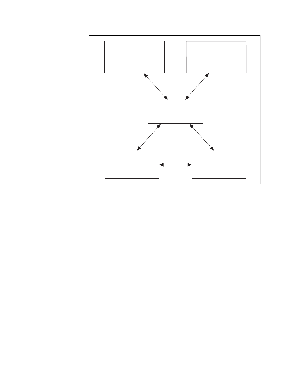
with minimal modifications to your code. Figure 1-1 illustrates the
relationship between NI-DAQ and your National Instruments
application software.
©
National Instruments Corporation 1-3 PC-DIO-24/PnP User Manual
Page 17
Chapter 1 Introduction
Programming Environment
SCXI Hardware
Figure 1-1. The Relationship between the Programming Environment,
Register-Level Programming
The final option for programming any National Instruments DAQ
hardware is to write register-level software. Writing register-level
programming software can be very time-consuming and inefficient,
and is not recommended for most users.
Conventional
DAQ or
ComponentWorks,
LabVIEW,
LabWindows/CVI, or
VirtualBench
NI-DAQ
Driver Software
Personal
Computer or
Workstation
NI-DAQ, and Your Hardware
Even if you are an experienced register-level programmer, consider
using National Instruments application software to program your
National Instruments DAQ hardware. Using the National Instruments
application software is easier than, and as flexible as, register-level
programming, and can save weeks of development time.
PC-DIO-24/PnP User Manual 1-4
©
National Instruments Corporation
Page 18

Optional Equipment
National Instruments offers a variety of products to use with your
PC-DIO-24/PnP board, including cables, connector blocks, and other
accessories, as follows:
• Cables and cable assemblies, shielded and ribbon
• Connector blocks, shielded and unshielded 50-pin screw terminals
• SCXI modules and accessories for isolating, amplifying, exciting,
and multiplexing signals for relays and analog output. With SCXI
you can condition and acquire up to 3,072 channels.
• Low channel-count signal conditioning modules, boards, and
accessories, including conditioning for strain gauges and RTDs,
simultaneous sample and hold, and relays.
For more specific information about these products, refer to your
National Instruments catalogue or call the office nearest you.
Note: The PC-DIO-24/PnP can drive the SSR-ODC-5 output module and all SSR
input modules available from National Ins truments, but c annot reli ably
sink sufficient current to drive the SSR-OAC-5 and SSR-OAC-5A output
modules.
Chapter 1 Introduction
To drive a SSR-OAC-5 or SSR-OAC-5A, you can either use a non-inverting
digital buffer chip between the PC-DIO-24/PnP and the SSR backplane, or
use another National Instruments board with higher drive current.
Custom Cables
National Instruments offers cables and accessories for you to prototype
your application or to use if you frequently change board
interconnections.
If you want to develop your own cable, however, the following
guidelines may be useful.
The PC-DIO-24/PnP I/O connector is a 50-pin male ribbon-cable
header. The manufacturer part numbers used by National Instruments
for this header are as follows:
• Electronic Products Division/3M (part number 2550-5002)
• T&B/Ansley Corporation (part number 609-5007)
©
National Instruments Corporation 1-5 PC-DIO-24/PnP User Manual
Page 19

Chapter 1 Introduction
The mating connector for the PC-DIO-24/PnP is a 50-position,
polarized, ribbon socket connector with strain relief. National
Instruments uses a polarized (keyed) connector to prevent inadvertent
upside-down connection to the PC-DIO-24/PnP. Recommended
manufacturer part numbers for this mating connector are as follows:
• Electronic Products Division/3M (part number 3425-7650)
• T&B/Ansley Corporation (part number 622-5041)
The standard ribbon cables (50-conductor, 28 AWG, stranded) that can
be used with these connectors are as follows:
• Electronic Products Division/3M (part number 3365/50)
• T&B/Ansley Corporation (part number 171-50)
Recommended manufacturer part numbers for the 50-pin edge
connector for connecting to a module rack with an edge connector are
as follows:
• Electronic Products Division/3M (part number 3415-0001)
• T&B Ansley Corporation (part number 622-5015)
A polarizing key can be plugged into these edge connectors to prevent
inadvertent upside-down connection to the I/O module rack. The
location of this key varies from rack to rack. Consult the specification
for the rack you intend to use for the location of any polarizing key. The
recommended manufacturer part numbers for this polarizing key are as
follows:
• Electronic Products Division/3M (part number 3439-2)
• T&B Ansley Corporation (part number 622-0005)
PC-DIO-24/PnP User Manual 1-6
©
National Instruments Corporation
Page 20

Unpacking
Chapter 1 Introduction
Your PC-DIO-24/PnP board is shipped in an antistatic package to
prevent electrostatic damage to the board. Electrostatic discharge can
damage several components on the board. To avoid such damage in
handling the board, take the following precautions:
• Ground yourself via a grounding strap or by holding a grounded
object.
• Touch the antistatic package to a metal part of your PC chassis
before removing the board from the package.
• Remove the board from the package and inspect the board for loose
components or any other sign of damage. Notify National
Instruments if the board appears damaged in any way.
install a damaged board into your computer.
Never
•
touch exposed connector pins.
Do not
©
National Instruments Corporation 1-7 PC-DIO-24/PnP User Manual
Page 21
Installation and
Chapter
Configuration
This chapter describes how to install and configure the
PC-DIO-24/PnP.
Installation
Note:
Install your driver software before installing your hardware. Refer to your
NI-DAQ release notes for software installation instructions.
2
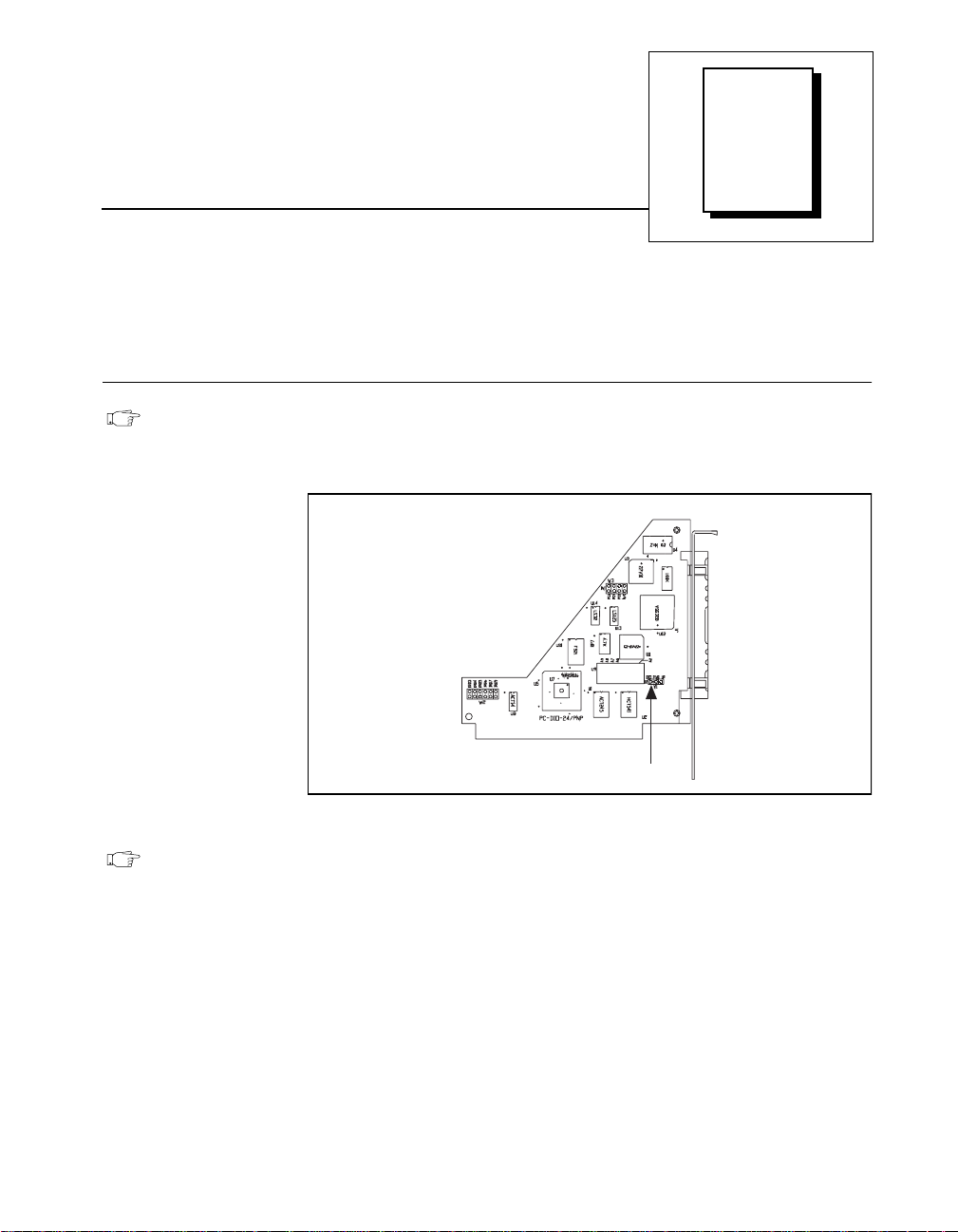
W1
Figure 2-1.
Note:
©
National Instruments Corporation 2-1 PC-DIO-24/PnP User Manual
The PC-DIO-24/PnP uses 100 kΩ resistors for polarity selection at
power-up. You can use jumper W1 to select whether data signals are pulled
up to Vcc (+5 VDC), factory default, or pulled down to GND. Figure 2-1
shows jumper W1. For more information, see the
State Selection
You can install the PC-DIO-24/PnP in any unused 8- or 16-bit
expansion slot in your computer. The following are general installation
instructions, but consult your computer user manual or technical
reference manual for specific instructions and warnings.
section in Chapter 3,
Jumper W1 Location
Digital I/O Power-up
Signal Connections
.
Page 22

Chapter 2 Installation and Configuration
1. Turn off and unplug your computer.
2. Remove the I/O channel top cover or access port.
3. Remove the expansion slot cover on the computer back panel.
4. Insert the PC-DIO-24/PnP into any 8- or 16-bit slot. It may be a
tight fit, but
5. Screw the PC-DIO-24/PnP mounting bracket to the computer back
panel rail.
6. Visually verify the installation.
7. Replace the computer cover.
8. Plug in and turn on your computer.
The PC-DIO-24/PnP board is now installed.
Hardware Configuration
Plug and Play
The PC-DIO-24PnP is fully compatible with the industry-standard
Intel/Microsoft Plug and Play Specification. A Plug and Play system
arbitrates and assigns resources through software, freein g you from
manually setting switches and jumpers. These resources include the
PC-DIO-24PnP base I/O address and interrupt channel.
do not
force the board into place.
The Configuration Manager receives all of the resource requests at
startup, compares the available resources to those requested, and
assigns the available resources as efficiently as possible to the Plug and
Play boards. Application software can query the Configuration
Manager to determine the resources assigned to each board without
your involvement. The Plug and Play software is installed as a device
driver or as an integral component of the computer BIOS.
PC-DIO-24/PnP User Manual 2-2
©
National Instruments Corporation
Page 23

Chapter 2 Installation and Configuration
Base I/O Address and Interrupt Selection
To change base I/O address or interrupt selection, refer to th e NI-DAQ
Configuration Utility Help file. You can configure the PC-DIO-24PnP
to use base addresses in the range of 100 to 3E0 hex. Each board
occupies 32 bytes of address space and must be located on a 32-byte
boundary. Therefore, valid addresses include 100, 120, 140…, 3 E0 hex.
The PC-DIO-24PnP can use interrupt channel 3, 4, 5, 7, or 9.
Note: To configure the non-Plug and Play PC-DIO-24 board, refer to
Appendix D,
Using Your PC-DIO-24 (Non-PnP) Board
.
©
National Instruments Corporation 2-3 PC-DIO-24/PnP User Manual
Page 24

Chapter
Signal Connections
This chapter includes timing specifications and signal connection
instructions for the PC-DIO-24/PnP I/O connector.
Caution:
!
I/O Connector
Connections that exceed any of the maximum ratings of input or output
signals on the PC-DIO-24/PnP can damage the board and the PC. National
Instruments is
connections. Maximum ratings for each signal are given in this chapter
under the discussion of that signal.
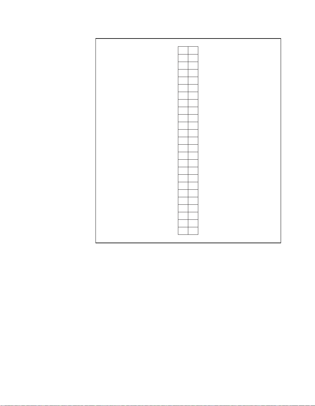
Figure 3-1 shows the pin assignments for the PC-DIO-24/PnP digital
I/O connector.
liable for any damages resulting from any such signal
NOT
3
©
National Instruments Corporation 3-1 PC-DIO-24/PnP User Manual
Page 25
Chapter 3 Signal Connections
PC7
PC6
PC5
PC4
PC3
PC2
PC1
PC0
PB7
PB6
PB5
PB4
PB3
PB2
PB1
PB0
PA7
PA6
PA5
PA4
PA3
PA2
PA1
PA0
+5 V
12
34
56
78
910
11 12
13 14
15 16
17 18
19 20
21 22
23 24
25 26
27 28
29 30
31 32
33 34
35 36
37 38
39 40
41 42
43 44
45 46
47 48
49 50
GND
GND
GND
GND
GND
GND
GND
GND
GND
GND
GND
GND
GND
GND
GND
GND
GND
GND
GND
GND
GND
GND
GND
GND
GND
Figure 3-1. Digital I/O Connector Pin Assignments
PC-DIO-24/PnP User Manual 3-2
©
National Instruments Corporation
Page 26
Signal Descriptions
Table 3-1 describes the PC-DIO-24/PnP signals.
Chapter 3 Signal Connections
Table 3-1.
Signal
Pin
1, 3, 5, 7, 9, 11,
13, 15
17, 19, 21, 23, 25,
27, 29, 31
33, 35, 37, 39, 41,
43, 45, 47
49 +5 V +5 Volts—This pin is fused for up
All even-numbered
pins
The absolute maximum voltage input rating is –0.5 to +5.5 V with
respect to GND.
Name
PC<7..0> Port C—Bidirectional data lines for
PB<7..0> Port B—Bidirectional data lines for
PA<7..0> Port A—Bidirectional data lines for
GND Ground—These signals are
Signal Descriptions
Description
port C. PC7 is the MSB, PC0 the
LSB.
port B. PB7 is the MSB, PB0 the
LSB.
port B. PA7 is the MSB, PA0 the
LSB.
to 1 A at +4.65 to 5.25 V.
connected to the computer ground
reference.
Port C Pin Assignments
The signals assigned to port C depend on the mode in which the
82C55A is programmed. In mode 0, port C is treated as one 8-bit
I/O port. If port A or B is in mode 1 or 2, then some or all of the port C
lines are used for status and handshaking signals. Any unused lines are
available for general-purpose input and output. Table 3-2 summarizes
the signal assignments of port C for each programmable mode. Ports A
and B can be in different modes; the table does not show every possible
combination. See Appendix C,
register-level programming information.
©
National Instruments Corporation 3-3 PC-DIO-24/PnP User Manual
Register-Level Programming
, for
Page 27

Chapter 3 Signal Connections
Caution: During programming, note that each time you configure any port, output
!
ports A and C are reset to 0, and output port B is undefined.
Table 3-2.
Port C Signal Assignments
Group A Group B
Programming
Mode
PC7 PC6 PC5 PC4 PC3 PC2 PC1 PC0
Mode 0 I/O I/O I/O I/O I/O I/O I/O I/O
Mode 1 Input I/O I/O IBF
STBA* INTRASTBB* IBFB
A
B
Mode 1 Output OBFA* ACKA* I/O I/O INTRAACKB* OBFB* INTR
Mode 2 OBFA* ACKA* IBFASTBA* INTRAI/O I/O I/O
* Indicates that the signal is active low.
Digital I/O Signal Connections
The following specifications and ratings apply to the digital I/O lines.
The maximum input logic high and output logic high voltages assume a
Vcc supply voltage of 5.0 V.
The absolute maximum voltage rating is –0.5 to +5.5 V with respect to
GND.
INTR
B
B
Digital input specifications (referenced to GND):
Input logic high voltage 2.2 V min 5.3 V max
Input logic low voltage –0.3 V min 0.8 V max
Input high current
(Vin = 5 V, W1 set to pullup) — 11.0 µA max
Input high current
(Vin = 5 V, W1 set to pulldown) — 65 µA max
Input logic low current
(Vin = 0 V, W1 set to pullup) — –65 µA max
Input logic low current
(Vin = 0 V, W1 set to pulldown) — –11 µA max
PC-DIO-24/PnP User Manual 3-4
©
National Instruments Corporation
Page 28

Chapter 3 Signal Connections
Digital output specifications (referenced to GND):
Output logic high voltage 3.7 V min 5.0 V max
(I
= –2.5 mA)
ol
Output logic high voltage 2.7 V min 5.0 V max
(I
= –4 mA)
oh
Output logic low voltage 0 V min 0.4 V
(I
= 2.5 mA)
ol
Output logic low voltage 0 V min 0.5 V
(I
= 4 mA)
ol
Figure 3-2 depicts signal connections for thre e typical digital I/O
applications.
©
National Instruments Corporation 3-5 PC-DIO-24/PnP User Manual
Page 29
Chapter 3 Signal Connections
+5 V
LED
+5 V
TTL Signal
Switch
I/O Connector
41
43
45
47
67
69
71
73
+5 V
Jumper
Selectable (W1)
100 kΩ100 kΩ 100 kΩ 100 kΩ
PPI
Port A
PA<3..0>
100 kΩ 100 kΩ 100 kΩ 100 kΩ
PPI
Port B
PB<7..4>
50, 100
GND
PC-DIO-24/PnP
Figure 3-2. Digital I/O Connections
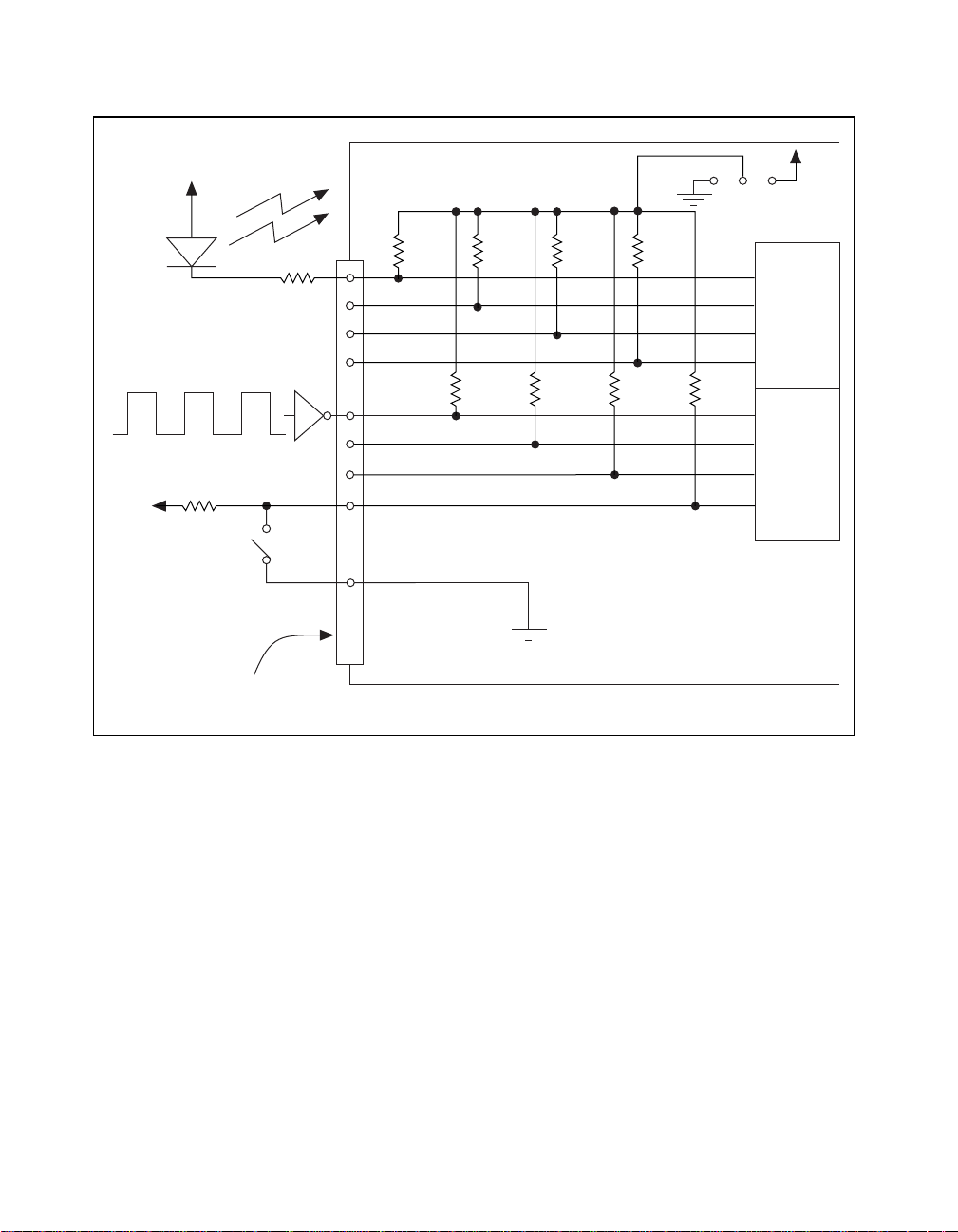
In Figure 3-2, port A is configured for digital output, and port B is
configured for digital input. Digital input applications include receiv ing
TTL signals and sensing external device states such as the state of the
switch in Figure 3-2. Digital output applications include sending TTL
signals and driving external devices such as the LED shown in this
figure.
PC-DIO-24/PnP User Manual 3-6
©
National Instruments Corporation
Page 30

Power Connections
Pin 49 of the I/O connector is connected to the +5 V supply from the PC
power supply. This pin is referenced to GND and can be u sed to power
external digital circuitry. This +5 V supply has a 1 A self-resetting
protection fuse in series. Simply remove the circuit causing the heavy
current load and the fuse will reset itself.
Power rating 1 A at +4.65 to 5.25 V
Caution: Under no circumstances should this +5 V power pin be connected directly
!
to ground or to any other voltage source on the PC-DIO-24/PnP or any
other device. Doing so may damage the PC-DIO-24/PnP and the PC.
National Instruments is
connection.
liable for damage resulting from such a
NOT
Digital I/O Power-up State Selection
You can power up the PC-DIO-24/PnP digital I/O lines in a
user-defined state. The PC-DIO-24/PnP facilitates user-configurable
pull-up or pull-down. Each DIO channel is connected to a 100 kΩ
resistor and can be pulled high or low using jumper W1. You can
use W1 to pull all 24 DIO lines high or low. However, you may want to
pull individual lines in different directions. To do this properly, you
must understand the nature of the drive current on those lines and
adhere to TTL logic levels.
Chapter 3 Signal Connections
High DIO Power-up State
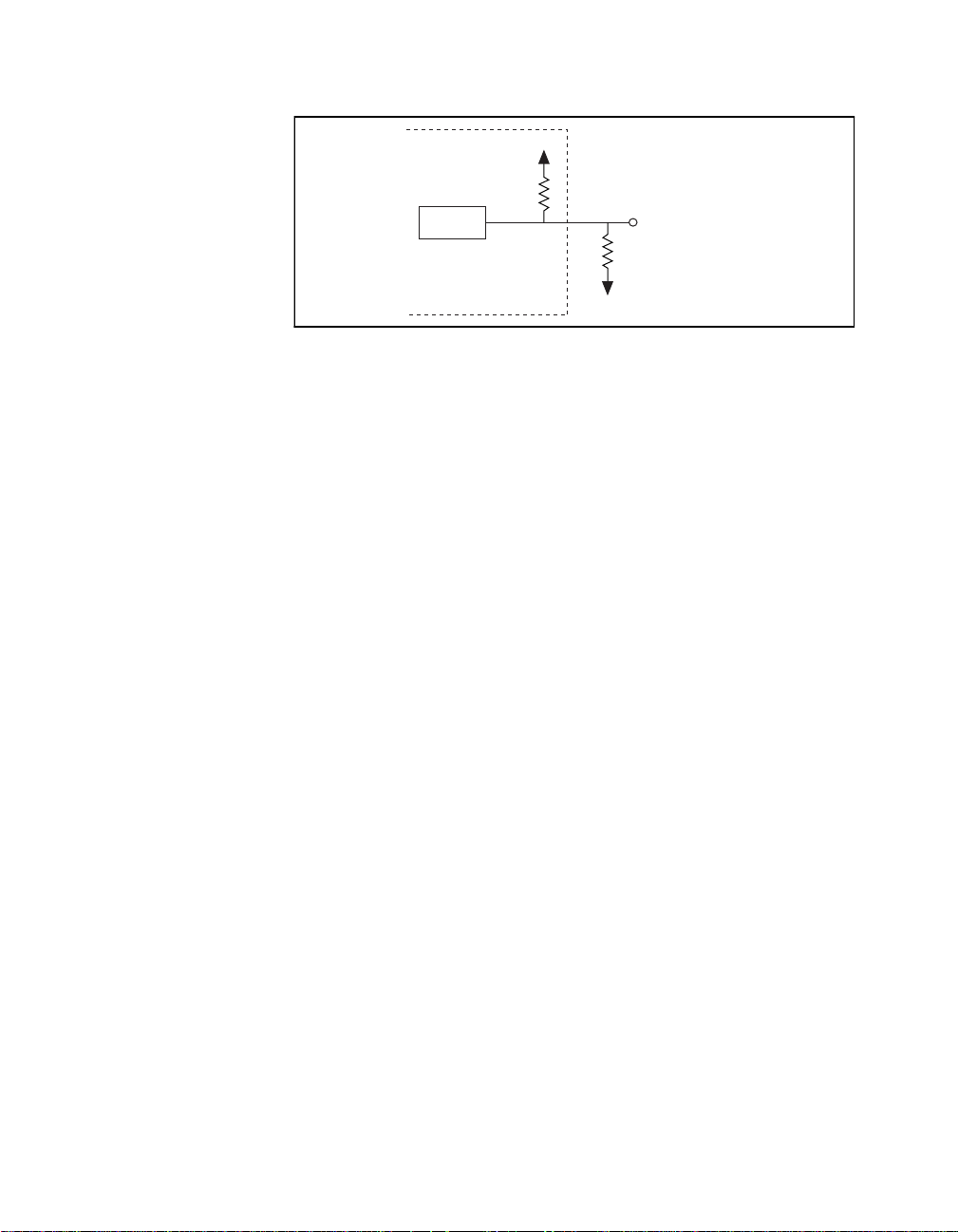
If you select the pulled-high mode, each DIO line will be pulled to Vcc
(approximately +5 VDC) with a 100 kΩ resistor. If you want to pull a
specific line low, connect between that line and ground a pull-down
resistor (R
the largest possible resistor ensures that you do not use more current
than necessary to perform the pull-down task, and that the DIO can still
drive the line. The DIO lines provide a maximum of 2.5 mA at 3.7 V in
the high state.
Also, make sure the resistor value is not so large that leakage current
from the DIO line along with the current from the 100 kΩ pull-up
resistor drives the voltage at the resistor above a TTL low level of
0.4 VDC.
©
National Instruments Corporation 3-7 PC-DIO-24/PnP User Manual
) whose value will give you a maximum of 0.4 VDC. Using
L
Page 31
Chapter 3 Signal Connections
PC-DIO-24/PnP
82C55A
Figure 3-3. DIO Channel Configured for High DIO Power-up State with External Load
100 kΩ
+5 V
GND
Digital I/O Line
R
L
Example:
At power up, the board is configured for input and, by default, all DIO
lines are high. To pull one channel low, follow these steps:
1. Install a load (R
). Remember that the smaller the resistance, the
L
greater the current consumption and the lower the voltage.
2. Using the following formula, calculate the largest possible load to
maintain a logic low level of 0.4 V with a minimum reduction to the
DIO drive current.
V = I * R
⇒ RL = V / I, where:
L
V= 0.4 V ;Voltage across R
L
I = 46µA + 11µA ;4.6 V across the 100 kΩ pull-up
resistor and 11µA max leakage
current
Therefore:
R
= 7.0 k
L
Ω
;0.4V / 57µA
This resistor value, 7.0 kΩ, provides a maximum of 0.4 V on the DIO
line at power up. You can substitute smaller resistor values to lower the
voltage or to provide a margin for Vcc variations and other factors.
However, smaller values will draw more current, leaving less drive
current for other circuitry connected to this line. The 7.0 kΩ resistor
reduces the amount of logic high source current by 0.4 mA with a 2.8 V
output.
PC-DIO-24/PnP User Manual 3-8
©
National Instruments Corporation
Page 32

Low DIO Power-up State
If you select pulled-low mode, each DIO line will be pulled to GND
(0 VDC ) using a 10 0 kΩ resistor. To pull a specific line high, connect
a pull-up resistor that will give you a minimum of 2.8 VDC. Using the
largest possible resistance value ensures that you do not to use more
current than necessary to perform the pull-up task, and that the DIO can
still drive the line. The DIO lines are capable of sinking a maximum of
2.5 mA at 0.4 V in the low state.
Also, make sure the pull-up resistor value is not so large that leakage
current from the DIO line along with the current from the 100 k Ω
pull-down resistor brings the voltage at the resistor below a TTL high
level of 2.8 VDC.
Chapter 3 Signal Connections
Figure 3-4.
PC-DIO-24/PnP
82C55A
100 kΩ
GND
DIO Channel Configured for Low DIO Power-up State with External Load
+5 V
R
L
Digital I/O Line
Example:
At power up, the board is configured for input and jumper W1 is set in
the low DIO power-up state, which means all DIO lines are pulled low.
If you want to pull one channel high, follow these steps:
1. Install a load (R
). Remember that the smaller the resistance, the
L
greater the current consumption and the higher the voltage.
2. Using the following formula, calculate the largest possible load to
maintain a logic high level of 2.8 V and supply the maximum sink
current.
V = I * R
⇒ RL = V / I, where:
L
V = 2.2 V ;voltage across R
L
I = 28 µA + 11 µA ;2 .8 V acro ss the 100 kΩ pull-up
resistor and 11 µA max leakage
current
©
National Instruments Corporation 3-9 PC-DIO-24/PnP User Manual
Page 33

Chapter 3 Signal Connections
Therefore:
This resistor value, 5.6 kΩ, provides a minimum of 2.8 V on the DIO
line at power up. You can substitute smaller resistor values but they will
draw more current, leaving less sink current for other circuitry
connected to this line. The 5.6 kΩ resistor will reduce the amount of a
logic low sink current by 0.8 mA with a 0.4 V output.
Timing Specifications
This section lists the timing specifications for handshaking with the
PC-DIO-24/PnP. The handshaking lines STB* and IBF synchronize
input transfers. The handshaking lines OBF* and ACK* synchronize
output transfers.
The signals in Table 3-3 are used in the timing diagrams on the
subsequent pages.
R
= 5.6 kΩ ;2.2 V / 39 µA
L
Table 3-3.
Timing Signal Descriptions
Signal
Name
Direction
Description
STB* Input Strobe Input—A low signal on this
handshaking line loads data into the input
latch.
IBF Output Input Buffer Full—A high signal on this
handshaking line indicates that data has
been loaded into the input latch. This is an
input acknowledge signal.
ACK* Input Acknowledge Input—A low signal on this
handshaking line indicates that the data
written from the selected port has been
accepted. This signal is a response from the
external device that it has received the data
from the PC-DIO-24/PnP.
OBF* Output Output Buffer Full—A low signal on this
handshaking line indicates that data has
been written to the selected port.
PC-DIO-24/PnP User Manual 3-10
©
National Instruments Corporation
Page 34

Chapter 3 Signal Connections
Table 3-3. Timing Signal Descriptions (Continued)
Signal
Name
Direction
Description
INTR Output Interrupt Request—This signal becomes
high when the 82C55A is requesting service
during a data transfer. The appropriate
interrupt enable bits must be set to generate
this signal.
RD* Internal Read Signal—This signal is the read signal
generated from the control lines of the PC.
WR* Internal Write Signal—This signal is the write signal
generated from the control lines of the PC.
DATA Bidirectional Data Lines at the Selected Port—This signal
indicates when the data on the data lines at a
selected port is available (output) or should
be available (input).
©
National Instruments Corporation 3-11 PC-DIO-24/PnP User Manual
Page 35

Chapter 3 Signal Connections
Mode 1 Input Timing
The following figure illustrates the timing specifications for an input
transfer in mode 1.
STB*
T1
T2
T4
T7
IBF
INTR
RD*
DATA
T3
T5
T6
Name Description Minimum Maximum
T1
T2
T3
T4
T5
T6
T7
All timing values are in nanoseconds.
STB* pulse width
STB* = 0 to IBF* = 1
Data before STB* = 1
STB* = 1 to INTR = 1
Data after STB* = 1
RD* = 0 to INTR = 0
RD* = 1 to IBF = 0
Figure 3-5.
Mode 1 Timing Specification for Input Transfers
100 —
—150
20 —
—150
50 —
—200
—150
PC-DIO-24/PnP User Manual 3-12
©
National Instruments Corporation
Page 36

Mode 1 Output Timing
The following figure illustrates the timing specifications for an output
transfer in mode 1.
WR*
OBF*
INTR
Chapter 3 Signal Connections
T3
T4
T1
T6
ACK*
DATA
T2
T5
Name Description Minimum Maximum
T1
T2
T3
T4
T5
T6
All timing values are in nanoseconds.
WR* = 0 to INTR = 0
WR* = 1 to output
WR* = 1 to OBF* = 0
ACK* = 0 to OBF* = 1
ACK* pulse width
ACK* = 1 to INTR = 1
Figure 3-6.
Mode 1 Timing Specification for Output Transfers
—250
—200
—150
—150
100 —
—150
©
National Instruments Corporation 3-13 PC-DIO-24/PnP User Manual
Page 37

Chapter 3 Signal Connections
Mode 2 Bidirectional Timing
The following figure illustrates the timing specifications for
bidirectional transfers in mode 2.
T1
WR*
OBF*
INTR
ACK*
STB*
T4
IBF
RD*
T2
T6
T7
T3
T10
T5
T8
T9
DATA
Name Description Minimum Maximum
T1
T2
T3
T4
T5
T6
T7
T8
T9
T10
All timing values are in nanoseconds.
PC-DIO-24/PnP User Manual 3-14
WR* = 1 to OBF* = 0
Data before STB*= 1
STB* pulse width
STB* = 0 to IBF = 1
Data after STB* = 1
ACK* = 0 to OBF = 1
ACK* pulse width
ACK* = 0 to output
ACK* = 1 to output float
RD* = 1 to IBF = 0
Figure 3-7.
Mode 2 Timing Specification for Bidirectional Transfers
—150
20 —
100 —
—150
50 —
—150
100 —
—150
20 250
—150
©
National Instruments Corporation
Page 38

Chapter
Theory of Operation
This chapter contains a functional overview of the PC-DIO-24/PnP
board and explains the operation of each functional unit making up the
PC-DIO-24/PnP.
Functional Overview
The block diagram in Figure 4-1 illustrates the key functional
components of the PC-DIO-24/PnP board.
Bus
Transceivers
Bus Interface
(Plug and Play)
PC I/O Channel
Address
Decode
+5 V
Interrupt
Circuitry
82C55A
Interrupt
Control
Circuitry
PPI
1 A Fuse
PA
/
8
PB
/
8
PC
/
8
PC3
PC0
4
I/O Connector
Figure 4-1.
The PC I/O channel consists of an address bus, a data bus, interrupt
lines, and several control and support signals. Control and data transfers
to the system microprocessor are asynchronous.
©
National Instruments Corporation 4-1 PC-DIO-24/PnP User Manual
PC-DIO-24/PnP Block Diagram
Page 39

Chapter 4 Theory of Operation
Bus Transceivers
The bus transceivers send and receive data lines and other signals to and
from the PC I/O channel.
Bus Interface
The PC-DIO-24PnP Plug and Play circuitry automatically arbitrates
and assigns system resources. Software performs all bus-related
configuration, such as setting the board base address and interrupt level.
On the PC-DIO-24 (non-PnP), switches and jumpers set the board base
address and interrupt level.
Interrupt Control Circuitry
The PC-DIO-24PnP interrupt channel is selected by the Plug and Play
circuitry. Two software-controlled registers determine what sources, if
any, can generate interrupts. The 82C55A device has two interrupt
lines, PC3 and PC0, connected to the interrupt circuitry.
The PC-DIO-24 (non-PnP) uses one of the extra PC lines
(jumper-selectable) as an interrupt enable.
82C55A Programmable Peripheral Interface
The 82C55A PPI chip is the heart of the PC-DIO-24/PnP. This chip has
24 programmable I/O pins that represent three 8-bit ports—PA, PB, and
PC. You can program each port as an input or an output port. The
82C55A has three modes of operation—simple I/O (mode 0),
strobed I/O (mode 1), and bidirectional I/O (mode 2). In mode 1, the
three ports are divided into two groups—group A and group B. Each
group has eight data bits and three control and status bits from port C
(PC). Group A can also use mode 2. In mode 2, group A has one 8-bit
bidirectional data port and five control and status bits from port C. You
can use port A and port B in two different modes. Modes 1 and 2 use
handshaking signals from port C to synchronize data transfers. Refer to
Chapter 4,
Sheet,
PC-DIO-24/PnP User Manual 4-2
Theory of Operation
for more detailed information.
, or to Appendix B,
OKI 82C55A Data
©
National Instruments Corporation
Page 40

Digital I/O Connector
All digital I/O is transmitted through a standard, 50-pin, male
connector. Pin 49 is connected to +5 V through a resettable protection
fuse. You can use this +5 V supply to operate I/O module mounting
racks. Even-numbered pins are connected to ground. See the
Equipment
Signal Connections
section in Chapter 1,
, for additional information.
Introduction
Chapter 4 Theory of Operation
Optional
, as well as Chapter 3,
©
National Instruments Corporation 4-3 PC-DIO-24/PnP User Manual
Page 41

Appendix
Specifications
This appendix lists the specifications for the PC-DIO-24/PnP board.
These specifications are typical at 25° C, unless otherwise s tated. The
operating temperature range is 0° to 70° C.
Digital I/O
Number of channels............................24 I/O
Compatibility......................................TTL
Absolute max voltage input rating
(Vcc = 5.0 V)......................................–0.5 to +5.5 V with
Handshaking.......................................Requires one port
Power-on state ....................................Configured as inputs, pulled
Data transfers...................................... Interrupts, programmed I/O
A
respect to GND
high or low (jumper-selectable)
Digital Logic Levels
Input Signals
The maximum input logic high and output logic high voltages assume a
Vcc supply voltage of 5.0 V.
Level Min Max
Input logic high voltage 2.2 V 5.3 V
Input logic low voltage –0.3 V 0.8 V
Input high current
(V
= 5 V, W1 set to pullup)
in
©
National Instruments Corporation A-1 PC-DIO-24/PnP User Manual
— 11.0 µA
Page 42
Appendix A Specifications
Level Min Max
Input high current
(V
= 5 V, W1 set to pulldown)
in
Input logic low current
(Vin = 0 V, W1 set to pullup)
Input logic low current
(Vin = 0 V, W1 set to pulldown)
— 65 µA
— –65 µA
— –11 µA
Output Signals
Pin 49 (at 4.65 to 5.25 VDC).............. 1.0 A max
Level Min Max
Output logic high voltage
(I
= –2.5 mA)
ol
Output logic high voltage
(I
= –4 mA)
oh
Output logic low voltage
(I
= 2.5 mA)
ol
Output logic low voltage
(I
= 4 mA)
ol
3.7 V 5.0 V
2.7 V 5.0 V
0 V 0.4 V
0 V 0.5 V
Power Requirement
+5 VDC (±10%)................................. 0.45 A typ, 1 A max
Physical
Dimensions ........................................ 11.7 by 10.6 cm (4.6 by 4.2 in.)
I/O connector ..................................... 50-pin male ribbon-cable
PC-DIO-24/PnP User Manual A-2
connector
©
National Instruments Corporation
Page 43

Environment
Transfer Rates
Appendix A Specifications
Operating temperature ........................0° to 70° C
Storage temperature............................–55° to 150° C
Relative humidity ...............................5% to 90% noncondensing
Max with NI-DAQ software................50 kbytes/s
Constant sustainable rate (typ)............ 1 to 10 kbytes/s
Transfer rates are a function of the speed with which your program
reads data from or writes data to the board, and therefore vary with your
system, software, and application. The following primary factors
control PC-DIO-24/PnP transfer rates:
• Computer system performance
• Programming environment (register-level programming or
NI-DAQ)
• Programming language and code efficiency
• Execution mode (foreground or background, with background
execution typically using interrupts)
• Other operations in progress
• Application
For example, you can obtain higher transfer rates in a handshaking or
data-transfer application, requiring an average rate, than in a pattern
generation, data acquisition, or waveform generation application,
requiring a constant sustainable rate.
The maximum rate shown was obtained using a 233 MHz Pentium
computer running NI-DAQ and LabWindows/CVI software, with
interrupt-based execution, and with no other high-speed operations in
progress.
©
National Instruments Corporation A-3 PC-DIO-24/PnP User Manual
Page 44

Appendix
OKI 82C55A Data Sheet
This appendix contains the manufacturer data sheet for the OKI
Semiconductor* 82C55A CMOS PPI. This interface is used on the
PC-DIO-24/PnP board.
B
* Copyright © OKI Semiconductor 1995. Reprinted with permission of copyright owner. All rights reserved.
OKI Semiconductor Data Book
©
National Instruments Corporation B-1 PC-DIO-24/PnP User Manual
Microprocessor
, Eighth Edition, January 1995.
Page 45

Appendix B OKI 82C55A Data Sheet
PC-DIO-24/PnP User Manual B-2
©
National Instruments Corporation
Page 46
Appendix B OKI 82C55A Data Sheet
©
National Instruments Corporation B-3 PC-DIO-24/PnP User Manual
Page 47

Appendix B OKI 82C55A Data Sheet
PC-DIO-24/PnP User Manual B-4
©
National Instruments Corporation
Page 48

Appendix B OKI 82C55A Data Sheet
©
National Instruments Corporation B-5 PC-DIO-24/PnP User Manual
Page 49

Appendix B OKI 82C55A Data Sheet
PC-DIO-24/PnP User Manual B-6
©
National Instruments Corporation
Page 50

Appendix B OKI 82C55A Data Sheet
©
National Instruments Corporation B-7 PC-DIO-24/PnP User Manual
Page 51

Appendix B OKI 82C55A Data Sheet
PC-DIO-24/PnP User Manual B-8
©
National Instruments Corporation
Page 52

Appendix B OKI 82C55A Data Sheet
©
National Instruments Corporation B-9 PC-DIO-24/PnP User Manual
Page 53

Appendix B OKI 82C55A Data Sheet
PC-DIO-24/PnP User Manual B-10
©
National Instruments Corporation
Page 54

Appendix B OKI 82C55A Data Sheet
©
National Instruments Corporation B-11 PC-DIO-24/PnP User Manual
Page 55

Appendix B OKI 82C55A Data Sheet
PC-DIO-24/PnP User Manual B-12
©
National Instruments Corporation
Page 56

Appendix B OKI 82C55A Data Sheet
©
National Instruments Corporation B-13 PC-DIO-24/PnP User Manual
Page 57

Appendix B OKI 82C55A Data Sheet
PC-DIO-24/PnP User Manual B-14
©
National Instruments Corporation
Page 58

Appendix B OKI 82C55A Data Sheet
©
National Instruments Corporation B-15 PC-DIO-24/PnP User Manual
Page 59

Appendix B OKI 82C55A Data Sheet
PC-DIO-24/PnP User Manual B-16
©
National Instruments Corporation
Page 60

Appendix B OKI 82C55A Data Sheet
©
National Instruments Corporation B-17 PC-DIO-24/PnP User Manual
Page 61

Register-Level
Appendix
Programming
This appendix describes in detail the ad dress and function of each of t he
PC-DIO-24/PnP control and status registers. This appendix also
includes important information about register-level programming on
the PC-DIO-24/PnP along with program examples written in C and
assembly language.
Note:
Introduction
If you plan to do application-level programming using software such as
LabVIEW, LabWindows/CVI, or NI-DAQ with your PC-DIO-24/PnP
board, you need not read this appendix.
You can configure your PC-DIO-24PnP board to use base addresses in
the range of 100 to 3E0 hex. Your PC-DIO-24PnP board occupies
32 bytes of address space and must be located on a 32-byte boundary.
Therefore, valid addresses include 100, 120, 140..., 3E0 hex. The base
I/O address is software-configured and does not require you to
manually change any board settings. For more information on
configuring the PC-DIO-24PnP, see Chapter 2 ,
Configuration
C
Installation and
.
The PC-DIO-24 non-PnP board occupies four bytes of address space
and must be located on a four-byte boundary. For more information on
configuring the PC-DIO-24, see Appendix D,
(Non-PnP) Board
In addition to the 82C55A device, the PC-DIO-24PnP has two registers
that select which interrupt sources are capable of generating interrupts.
Individual enable bits select whether port A or port B interrupt signals
from the 82C55A device generate interrupt requests. A master interrupt
enable bit determines whether the board can actually send interrupt
requests to the host computer. The configuration bits for these registers
are defined in the
Registers
©
National Instruments Corporation C-1 PC-DIO-24/PnP User Manual
section in this appendix.
.
Register Description for the Interrupt Control
Using Your PC-DIO-24
Page 62

Appendix C Register-Level Programming
The PC-DIO-24 (non-PnP) does not have interrupt control registers.
Instead, it uses one of the port C lines to enable or disable interrupts.
See Appendix D,
information.
The three 8-bit ports of the 82C55A are divided into two groups of
12 signals each: group A and group B. One 8-bit control word selects
the modes of operation for both groups. The group A control bits
configure port A (A7 through A0) and the upper 4 bits (nibble) of
port C (C7 through C4). The group B control bits configure port B
(B7 through B0) and the lower nibble of port C (C3 through C0). These
configuration bits are defined in the
82C55A
The 82C55A potentially requires up to 200 ns recovery time between
consecutive read or write cycles. Certain computers may provide
slightly less time than this between two back-to-back assemblylanguage reads or writes. If you are programming in assembly language,
it is therefore recommended that you separate two 82C55A reads or
writes with at least one other instruction.
Using Your PC-DIO-24 (Non-PnP) Board
section later in this appendix.
for more
Register Description for the
PC-DIO-24/PnP User Manual C-2
©
National Instruments Corporation
Page 63

Register Map
Appendix C Register-Level Programming
The following table lists the address map for the PC-DIO-24/PnP.
Table C-1.
Register Name
82C55A Register Group
PORTA Register 00 8-bit Read-and-write
PORTB Register 01 8-bit Read-and-write
PORTC Register 02 8-bit Read-and-write
CNFG Register 03 8-bit Write-only
Interrupt Control Register Group
(PC-DIO-24PnP only)
Register 1 14 8-bit Write-only
Register 2 15 8-bit Write-only
PC-DIO-24/PnP Address Map
Offset Address
(Hex)
Size Type
Register Description for the 82C55A
Figure C-1 shows the two control word formats used to completely
program the 82C55A. The control word flag determines which control
word format is being programmed. When the control word flag is 1,
bits 6 through 0 select the I/O characteristics of the 82C55A ports.
These bits also select the mode in which the ports are operating (that is,
mode 0, mode 1, or mode 2). When the control word flag is 0, bits 3
through 0 select the bit set/reset format of port C.
©
National Instruments Corporation C-3 PC-DIO-24/PnP User Manual
Page 64

Appendix C Register-Level Programming
Group A Group B
D2 D1 D0D5 D4 D3D7 D6
Control Word
Flag
1 = mode set
Mode Selection
00 = mode 0
01 = mode 1
1X = mode 2
Port A
1 = input
0 = output
Port C
(high nibble)
1 = input
0 = output
Control Word
Flag
0 = bit set/reset
Unused
D6 D5
a. Mode Set Word Format
D4
b. Bit Set/Reset Word Format
D2 D1 D0D3D7
Port C
(low nibble)
1 = input
0 = output
Port B
1 = input
0 = output
Mode Selection
0 = mode 0
1 = mode 1
Bit Set/Reset
1 = set
0 = reset
Bit Select
(000)
(001)
(010)
:
:
(111)
Figure C-1. Control Word Formats for the 82C55A
Caution: During programming, note that each time any port is configured, output
!
PC-DIO-24/PnP User Manual C-4
ports A and C are reset to 0, and output port B is undefined.
©
National Instruments Corporation
Page 65

Appendix C Register-Level Programming
Table C-2 shows the control words for setting or resetting each bit in
port C. Notice that bit 7 of the control word is cleared when
programming the set/reset option for the bits of port C.
Table C-2.
Bit Set Control
Bit Number
Port C Set/Reset Control Words
Bit Reset
Word
Control Word
0 0xxx0001 0xxx0000 xxxxxxxb
1 0xxx0011 0xxx0010 xxxxxxbx
2 0xxx0101 0xxx0100 xxxxxbxx
3 0xxx0111 0xxx0110 xxxxbxxx
4 0xxx1001 0xxx1000 xxxbxxxx
5 0xxx1011 0xxx1010 xxbxxxxx
6 0xxx1101 0xxx1100 xbxxxxxx
7 0xxx1111 0xxx1110 bxxxxxxx
Register Description for the Interrupt Control Registers
There are two interrupt control registers on the PC-DIO-24PnP. One of
these registers has individual enable bits for the two inter rupt lines from
the 82C55A device. The other register has a master interrupt enable bit.
When writing to these registers, set all reserved bits to zero. The bit
maps and signal definitions are listed as follows.
The Bit Set or
Reset in Port C
©
National Instruments Corporation C-5 PC-DIO-24/PnP User Manual
Page 66

Appendix C Register-Level Programming
Interrupt Control Register 1 (PnP Board Only)
D7 D6 D5 D4 D3 D2 D1 D0
x x x x x x IRQ1 IRQ0
Bit Name Description
2–7 x Reserved bit.
1 IRQ1 PPI Interrupt Request for Port B—If this bit and the
INTEN bit in Interrupt Control Register 2 are both set,
the PPI can send an interrupt, INTRB, to the host
computer. If this bit is cleared, the PPI does not send
the interrupt INTRB to the host computer, regardless
of the setting of INTEN.
0 IRQ0 PPI Interrupt Request for Port A—If this bit and the
INTEN bit in Interrupt Control Register 2 are both set,
the PPI can send an interrupt, INTRA, to the host
computer. If this bit is cleared, the PPI does not send
the interrupt INTRA to the host computer, regardless
of the setting of INTEN.
PC-DIO-24/PnP User Manual C-6
©
National Instruments Corporation
Page 67

Appendix C Register-Level Programming
Interrupt Control Register 2 (PnP Board Only)
D7 D6 D5 D4 D3 D2 D1 D0
X X X X X INTEN X X
Bit Name Description
1–0, 3–7 X Reserved Bit.
2 INTEN Global Interrupt Enable Bit—If this bit is set, the
PC-DIO-24PnP can interrupt the host computer. If this
bit is cleared, the board cannot interrupt the host
computer.
©
National Instruments Corporation C-7 PC-DIO-24/PnP User Manual
Page 68

Appendix C Register-Level Programming
Programming Considerations for the 82C55A
Modes of Operation for the 82C55A
The three basic modes of operation for the 82C55A are as follows:
• Mode 0—Basic I/O
• Mode 1—Strobed I/O
• Mode 2—Bidirectional bus
The 82C55A also has a single bit set/reset feature for port C, which is
programmed by the 8-bit control word. For additional information, refer
to Appendix B,
Mode 0
Use this mode for simple input and output operations for each of the
ports. No handshaking is required; simply write data to or read data
from a specified port.
Mode 0 has the following features:
• Two 8-bit ports (A and B) and two 4-bit ports (upper and lower
nibbles of port C).
• Any port can be input or output.
• Outputs are latched, but inputs are no t latched.
OKI 82C55A Data Sheet
.
Mode 1
This mode transfers data that is synchronized by handshaking signals.
Ports A and B use the eight lines of port C to generate or receive the
handshake signals. This mode divides the ports into two groups
(group A and group B) and includes the following features:
• Each group contains one 8-bit data port (port A or port B) and one
3-bit control/status port (upper or lower portion of port C).
• The 8-bit data ports can be either input or output, both of which are
latched.
• The 3-bit ports are used for control and status of the 8-bit data port s.
• Interrupt generation and enable/disable functions are available.
PC-DIO-24/PnP User Manual C-8
©
National Instruments Corporation
Page 69

Mode 0—Basic I/O
Appendix C Register-Level Programming
Mode 2
Use this mode for communication over a bidirectional 8-bit bus.
Handshaking signals are used in a manner similar to mode 1. Mode 2 is
available for use in group A only (port A and the upper portion of
port C). Other features of this mode include the following:
• One 8-bit bidirectional port (port A) and a 5-bit control/status port
(port C).
• Latched inputs and outputs.
• Interrupt generation and enable/disable functions.
Single Bit Set/Reset Feature
You can set or reset any of the eight bits of port C with one control
word. This feature generates control signals for port A and port B when
these ports are operating in mode 1 or mode 2.
Use mode 0 for simple I/O functions (no handshaking) for each of the
three ports. You can assign each port as an input or an output port. The
16 possible I/O configurations are shown in Table C-3. Notice that bit 7
of the control word is set when pr ogrammi ng th e mode of operation for
each port.
Table C-3.
Mode 0 I/O Configurations
Control Word Group A Group B
Bit
Number
76543210
Port A Port C
1
Port B Port C
2
0 10000000 Output Output Output Output
1 10000001 Output Output Output Input
2 10000010 Output Output Input Output
3 10000011 Output Output Input Input
4 10001000 Output Input Output Output
5 10001001 Output Input Output Input
6 10001010 Output Input Input Output
7 10001011 Output Input Input Input
8 10010000 Input Output Output Output
©
National Instruments Corporation C-9 PC-DIO-24/PnP User Manual
Page 70

Appendix C Register-Level Programming
Table C-3.
Mode 0 I/O Configurations (Continued)
Control Word Group A Group B
Bit
Number
76543210
Port A Port C
1
Port B Port C
2
9 10010001 Input Output Output Input
10 10010010 Input Output Input Output
11 10010011 Input Output Input Input
12 10011000 Input Input Output Output
13 10011001 Input Input Output Input
14 10011010 Input Input Input Output
15 10011011 Input Input Input Input
1
Upper nibble of port C
2
Lower nibble of port C
Mode 0 Programming Example
The following example shows how to configure the 82C55A for various
combinations of mode 0 input and output. This code is strictly an
example and is not intended to be used without modification in a
practical situation.
Main() {
#define BASE_ADDRESS 0x180 /* Board located at address 180 */
#define PORTAoffset 0x00 /* Offset for port A */
#define PORTBoffset 0x01 /* Offset for port B */
#define PORTCoffset 0x02 /* Offset for port C */
#define CNFGoffset 0x03 /* Offset for CNFG */
unsigned int porta, portb, portc, cnfg;
char valread; /* Variable to store data read from a port */
/* Calculate register addresses */
porta = BASE_ADDRESS + PORTAoffset;
portb = BASE_ADDRESS + PORTBoffset;
portc = BASE_ADDRESS + PORTCoffset;
cnfg = BASE_ADDRESS + CNFGoffset;
/* EXAMPLE 1*/
outp(cnfg,0x80); /* Ports A, B, and C are outputs. */
outp(porta,0x12); /* Write data to port A. */
outp(portb,0x34); /* Write data to port B. */
PC-DIO-24/PnP User Manual C-10
©
National Instruments Corporation
Page 71

Appendix C Register-Level Programming
outp(portc,0x56); /* Write data to port C. */
/* EXAMPLE 2*/
outp(cnfg,0x90); /* Port A is input; ports B and C are outputs. */
outp(portb,0x22); /* Write data to port B. */
outp(portc,0x55); /* Write data to port C. */
valread = inp(porta); /* Read data from port A. */
/* EXAMPLE 3 */
outp(cnfg,0x82); /* Ports A and C are outputs;
port B is an input. */
/* EXAMPLE 4 */
outp(cnfg,0x89); /* Ports A and B are outputs;
port C is an input. */
}
Mode 1—Strobed Input
In mode 1, the digital I/O bits are divided into two groups: group A and
group B. Each of these groups contains one 8-bit port and one 3-bit
control/data port. The 8-bit port can be ei ther an input or an output port,
and the 3-bit port is used for control and status information for the 8-bit
port. The transfer of data is synchronized by handshaking signals in the
3-bit port.
The control word written to the CNFG Register to configure port A for
input in mode 1 is shown as follows. Use bits PC6 and PC7 of port C as
extra input or output lines.
D6 D5
1
0
©
National Instruments Corporation C-11 PC-DIO-24/PnP User Manual
D4
1/0
D2 D1 D0D3D7
X
Port C bits PC6 and PC7
1 = input
0 = output
X11
X
Page 72

Appendix C Register-Level Programming
The control word written to the CNFG Register to configure port B for
input in mode 1 is shown as follows. Notice that port B does not have
extra input or output lines left from port C when ports A and B are both
enabled for handshaking.
1
D6 D5
X
X
D4
X11X
D2 D1 D0D3D7
X
During a mode 1 data read transfer, the status of the handshaking lines
and interrupt signals can be obtained by reading port C. The port C
status-word bit definitions for an input transfer are shown as follows.
Port C status-word bit definitions for input (port A and port B):
D7 D6 D5 D4 D3 D2 D1 D0
I/O I/O IBFA INTEA INTRA INTEB IBFB INTRB
Bit Name Description
7–6 I/O Input/Output—These bits can be used for general-
purpose I/O when port A is in mode 1 input. If these
bits are configured for output, the port C bit set/reset
function must be used to manipulate them.
5 IBFA Input Buffer for Port A—A high setting indicates that
data has been loaded into the inpu t latc h for po rt A.
4 INTEA Interrupt Enable Bit for Port A—Setting this bit
enables interrupts from port A of the 82C55A. This bit
is controlled by setting/resetting PC4.
3 INTRA Interrupt Request Status for Port A—When INTEA
and IBFA are high, this bit is high, indicating that an
interrupt request is pending for port A.
2 INTEB Interrupt Enable Bit for Port B—Setting this bit
enables interrupts from port B of the 82C55A. This bit
is controlled by setting/resetting PC2.
1 IBFB Input Buffer for Port B—A high setting indicates that
data has been loaded into the inpu t latc h for po rt B.
PC-DIO-24/PnP User Manual C-12
©
National Instruments Corporation
Page 73

Appendix C Register-Level Programming
0 INTRB Interrupt Request Status for Port B—When INTEB
and IBFB are high, this bit is high, indicating that an
interrupt request is pending for port B.
At the digital I/O connector, port C has the following pin assignments
when in mode 1 input. Notice that the status of STBA* and the status of
STBB* are not included in the port C status word.
Group A
Group B
PC7
PC6
PC5
PC4
PC3
PC2
PC1
PC0
I/O
I/O
IBFA
STBA*
INTRA
STBB*
IBFB
INTRB
Figure C-2. Port C Pin Assignments, Mode 1 Input
Mode 1 Input Programming Example
The following example shows how to configure PPI A for various
combinations of mode 1 input. This code is strictly an example and is
not intended to be used without modification in a practical situation.
Main() {
#define BASE_ADDRESS 0x180 /* Board located at address 180 */
#define PORTAoffset 0x00 /* Offset for port A */
#define PORTBoffset 0x01 /* Offset for port B */
#define PORTCoffset 0x02 /* Offset for port C */
#define CNFGoffset 0x03 /* Offset for CNFG */
unsigned int porta, portb, portc, cnfg;
char valread; /* Variable to store data read from a port */
/* Calculate register addresses */
porta = BASE_ADDRESS + PORTAoffset;
portb = BASE_ADDRESS + PORTBoffset;
portc = BASE_ADDRESS + PORTCoffset;
cnfg = BASE_ADDRESS + CNFGoffset;
©
National Instruments Corporation C-13 PC-DIO-24/PnP User Manual
Page 74

Appendix C Register-Level Programming
/* EXAMPLE 1–port A input */
outp(cnfg,0xB0); /* Port A is an input in mode 1. */
while (!(inp(portc) & 0x20)); /* Wait until IBFA is set,
indicating that data has been
loaded in port A. */
valread = inp(porta); /* Read the data from port A. */
/* EXAMPLE 2–Port B input */
outp(cnfg,0x86); /* Port B is an input in mode 1. */
while (!(inp(portc) & 0x02)); /* Wait until IBFB is set,
indicating that data has been
loaded in port B. */
valread = inp(portb);
}
Mode 1—Strobed Output
The control word written to the CNFG Register to configure port A for
output in mode 1 is shown as follows. Bits PC4 and PC5 of port C can
be used as extra input or output lines.
D6 D5
1
0
The control word written to the CNFG Register to configure port B for
output in mode 1 is shown as follows. Notice that port B does not have
extra input or output lines left from port C when ports A and B are both
enabled for handshaking.
D6 D5
1
X
During a mode 1 data write transfer, the status of the handshaking lines
and interrupt signals can be obtained by reading port C. Notice that the
bit definitions are different for a write and a read transfer.
PC-DIO-24/PnP User Manual C-14
1/0
D2 D1 D0D3D7
X
X
Port C bits PC4 and PC5
1 = input
0 = output
D2 D1 D0D3D7
X
©
National Instruments Corporation
X10
D4
D4
X11X
X
Page 75

Appendix C Register-Level Programming
Port C status-word bit definitions for output (port A and port B):
D7 D6 D5 D4 D3 D2 D1 D0
OBFA* INTEA I/O I/O INTRA INTEB OBFB* INTRB
Bit Name Description
7 OBFA* Output Buffer for Port A—A low setting indicates that
the CPU has written data to port A.
6 INTEA Interrupt Enable Bit for Port A—Setting this bit
enables interrupts from port A of the 82C55A. This bi t
is controlled by setting/resetting PC6.
5–4 I/O Input/Output—These bits can be used for general-
purpose I/O when port A is in mode 1 output. If these
bits are configured for output, the port C bit set/reset
function must be used to manipulate them.
3 INTRA Interrupt Request Status for Port A—When INTEA
and OBFA* are high, this bit is high, indicating that an
interrupt request is pending for port A.
2 INTEB Interrupt Enable Bit for Port B—Setting this bit
enables interrupts from port B of the 82C55A. This bi t
is controlled by setting/resetting PC2.
1 OBFB* Output Buffer for Port B—A low setting indicates that
the CPU has written data to port B.
0 INTRB Interrupt Request Status for Port B—When INTEB
and OBFB* are high, this bit is high, indicating that an
interrupt request is pending for port B.
At the digital I/O connector, port C has the following pin assignments
when in mode 1 output. Notice that the status of ACKA* and the st at us
of ACKB* are not included when port C is read.
©
National Instruments Corporation C-15 PC-DIO-24/PnP User Manual
Page 76

Appendix C Register-Level Programming
Group A
Group B
PC7
PC6
PC5
PC4
PC3
PC2
PC1
PC0
OBFA*
ACKA*
I/O
I/O
INTRA
ACKB*
OBFB*
INTRB
Figure C-3. Port C Pin Assignments, Mode 1 Output
Mode 1 Output Programming Example
The following example shows how to configure PPI A for various
combinations of mode 1 output. This code is strictly an example and is
not intended to be used without modification in a practical situation.
Main() {
#define BASE_ADDRESS 0x180 /* Board located at address 180 */
#define PORTAoffset 0x00 /* Offset for port A */
#define PORTBoffset 0x01 /* Offset for port B */
#define PORTCoffset 0x02 /* Offset for port C */
#define CNFGoffset 0x03 /* Offset for CNFG */
unsigned int porta, portb, portc, cnfg;
char valread; /* Variable to store data read from a port */
/* Calculate register addresses */
porta = BASE_ADDRESS + PORTAoffset;
portb = BASE_ADDRESS + PORTBoffset;
portc = BASE_ADDRESS + PORTCoffset;
cnfg = BASE_ADDRESS + CNFGoffset;
/* EXAMPLE 1–port A output */
outp(cnfg,0xA0); /* Port A is an output in mode 1.*/
while (!(inp(portc) & 0x80)); /* Wait until OBFA* is set,
indicating that the data last
written to port A has been
read.*/
outp(porta,0x12); /* Write data to port A. */
PC-DIO-24/PnP User Manual C-16
©
National Instruments Corporation
Page 77

Appendix C Register-Level Programming
/* EXAMPLE 2–port B output */
outp(cnfg,0x84); /* Port B is an output in mode 1.*/
while (!(inp(portc) & 0x02)); /* Wait until OBFB* is set,
indicating that the data last
written to port B has been
read.*/
outp(portb,0x34); /* Write the data to port B. */
}
Mode 2—Bidirectional Bus
Mode 2 has an 8-bit bus that can transfer both input and output data
without changing the configuration. The data transfers are synchronized
with handshaking lines in port C. This mode uses only port A; ho wever,
port B can be used in either mode 0 or mode 1 while port A is configured
for mode 2.
The control word written to the CNFG Register to configure port A as
a bidirectional data bus in mode 2 is shown as follows. If port B is
configured for mode 0, then PC2, PC1, and PC0 of port C can be used
as extra input or output lines.
D6 D5
1
Figure C-4.
©
National Instruments Corporation C-17 PC-DIO-24/PnP User Manual
D4
X
X
Port A Configured as a Bidirectional Data Bus in Mode 2
D2 D1 D0D3D7
X1
1/0
1/0
1/0
Port C
(PC2-PC0)
1 = input
0 = output
Port B
1 = input
0 = output
Group B Mode
0 = mode 0
1 = mode 1
Page 78

Appendix C Register-Level Programming
During a mode 2 data transfer, the status of the handshaking lines and
interrupt signals can be obtained by reading port C. The port C statusword bit definitions for a mode 2 transfer are shown as follows.
Port C status-word bit definitions for bidirectional data path (port A
only):
D7 D6 D5 D4 D3 D2 D1 D0
OBFA* INTE1 IBFA INTE2 INTRA I/O I/O I/O
Bit Name Description
7 OBFA* Output Buffer for Port A—A low setting indicates that
the CPU has written data to port A.
6 INTE1 Interrupt Enable Bit for Port A Output Interrupts—
Setting this bit enables output interrupts from port A
of the 82C55A. This bit is controlled by
setting/resetting PC6.
5 IBFA Input Buffer for Port A—A high setting indicates that
data has been loaded into the input la tch of port A.
4 INTE2 Interrupt Enable Bit for Port A Input Interrupts—
Setting this bit enables input interrupts from port A of
the 82C55A. This bit is controlled by setting/resetting
PC4.
3 INTRA Interrupt Request Status for Port A—If INTE1 and
IBFA are high, then this bit is high, indicating that an
interrupt request is pending for port A input transfers.
If INTE2 and OBFA* are high, then this bit is high,
indicating that an interrupt request is pending for
port A output transfers.
2–0 I/O Input/Output—These bits can be used for general-
purpose I/O lines if group B is configured for mod e 0.
If group B is configured for mode 1, refer to the bit
explanations shown in the preceding mode 1 sections.
PC-DIO-24/PnP User Manual C-18
©
National Instruments Corporation
Page 79

Appendix C Register-Level Programming
At the digital I/O connector, port C has the following pin assignments
when in mode 2. Notice that the status of STBA* and the status of
ACKA* are not included in the port C status word.
PC7
PC6
Group A
Group B
# The three port C lines associated with group B function are based on the mode selected
for group B; that is, if group B is configured for mode 0, PC2-PC0 function as generalpurpose input/output, but if group B is configured for mode 1 input or output, PC2PC0 function as handshaking lines as shown in the preceding mode 1 sections.
PC5
PC4
PC3
PC2
PC1
PC0
OBFA*
ACKA*
IBFA
STBA*
INTRA
#
#
#
Figure C-5. Port C Pin Assignments, Mode 2
Mode 2 Programming Example
The following example shows how to configure PPI A for mode 2 input
and output and how to use the handshaking signals to con trol data flow.
This code is strictly an example and is not intended to be used without
modification in a practical situation.
Main() {
#define BASE_ADDRESS 0x180 /* Board located at address 180 */
#define PORTAoffset 0x00 /* Offset for port A */
#define PORTBoffset 0x01 /* Offset for port B */
#define PORTCoffset 0x02 /* Offset for port C */
#define CNFGoffset 0x03 /* Offset for CNFG */
unsigned int porta, portb, portc, cnfg;
char valread; /* Variable to store data read from a port */
/* Calculate register addresses */
porta = BASE_ADDRESS + PORTAoffset;
portb = BASE_ADDRESS + PORTBoffset;
portc = BASE_ADDRESS + PORTCoffset;
©
National Instruments Corporation C-19 PC-DIO-24/PnP User Manual
Page 80

Appendix C Register-Level Programming
cnfg = BASE_ADDRESS + CNFGoffset;
/* EXAMPLE 1*/
outp(cnfg,0xC0); /* Port A is in mode 2. */
while (!(inp(portc) & 0x80)); /* Wait until OBFA* is set,
indicating that the data last
written to port A has been read.
*/
outp(porta,0x67); /* Write the data to port A. */
while (!(inp(portc) & 0x20)); /* Wait until IBFA is set,
indicating that data is
available in port A to be read.
*/
valread = inp(porta); /* Read data from port A. */
}
Interrupt Programming Examples for the 82C55A
The following examples show the process required to enable interrupts
for several different operating modes. The interrupt handling routines
and interrupt installation routines for the 82C55A are not included.
Consult your computer technical reference manual for additional
information. Also, if you generate interrupts with the PC3 or PC0 lines
of the 82C55A devices, you must maintain the active high level until the
interrupt service routine is entered. Otherwise, the host computer
considers the interrupt a spurious interrupt and routes the request to the
channel responsible for handling spurious interrupts. To prevent this
problem, try using some other I/O bit to send feedback to the device
generating the interrupt. In this way, the interrupting device can be
signaled that the interrupt service routine has been entered. For further
information on using PC3 and PC0 for interrupts, see the
Handling
section later in this appendix.
Interrupt
Note: The following code applies to the PC-DIO-24PnP. To adapt this code to the
PC-DIO-24 (non-PnP), remove the
replace
outp (ireg2, 0x04) with the following (assuming you use PC4
outp (ireg1) instructions and
as your interrupt enable):
outp (cnfg, 0x08) /* Clear PC4 to enable interrupts */
You cannot use PC4 as your interrupt enable in examples 1, 5, or 6,
because these configurations use PC4 for handshaking.
PC-DIO-24/PnP User Manual C-20
©
National Instruments Corporation
Page 81

Appendix C Register-Level Programming
Main() {
#define BASE_ADDRESS 0x180 /* Board located at address 180 */
#define PORTAoffset 0x00 /* Offset for port A */
#define PORTBoffset 0x01 /* Offset for port B */
#define PORTCoffset 0x02 /* Offset for port C */
#define CNFGoffset 0x03 /* Offset for CNFG */
#define IREG1offset 0x14 /* Offset for Interrupt Reg. 1 */
#define IREG2offset 0x15 /* Offset for Interrupt Reg. 2 */
unsigned int porta, portb, portc, cnfg, ireg1, ireg2;
char valread; /* Variable to store data read from a port */
/* Calculate register addresses */
porta = BASE_ADDRESS + PORTAoffset;
portb = BASE_ADDRESS + PORTBoffset;
portc = BASE_ADDRESS + PORTCoffset;
cnfg = BASE_ADDRESS + CNFGoffset;
ireg1 = BASE_ADDRESS + IREG1offset;
ireg2 = BASE_ADDRESS + IREG2offset;
/* EXAMPLE 1–Set up interrupts for mode 1 input for port A. Enable the
appropriate interrupt bits. */
outp(cnfg,0xB0); /* Port A is an input in mode 1. */
outp(cnfg,0x09); /* Set PC4 to enable interrupts from 82C55A. */
outp(ireg1,0x01); /* Set IRQ0 to enable port A interrupts. */
outp(ireg2,0x04); /* Set INTEN bit. */
/* EXAMPLE 2–Set up interrupts for mode 1 input for port B. Enable the
appropriate interrupt bits. */
outp(cnfg,0x86); /* Port B is an input in mode 1. */
outp(cnfg,0x05); /* Set PC2 to enable interrupts from 82C55A. */
outp(ireg1,0x02); /* Set IRQ1 to enable port B interrupts. */
outp(ireg2,0x04); /* Set INTEN bit. */
/* EXAMPLE 3–Set up interrupts for mode 1 output for port A. Enable the
appropriate interrupt bits. */
outp(cnfg,0xA0); /* Port A is an output in mode 1. */
outp(cnfg,0x0D); /* Set PC6 to enable interrupts from 82C55A. */
outp(ireg1,0x01); /* Set IRQ0 to enable port A interrupts. */
outp(ireg2,0x04); /* Set INTEN bit. */
/* EXAMPLE 4–Set up interrupts for mode 1 output for port B. Enable the
appropriate interrupt bits. */
outp(cnfg,0x84); /* Port B is an output in mode 1. */
outp(cnfg,0x05); /* Set PC2 to enable interrupts from 82C55A. */
©
National Instruments Corporation C-21 PC-DIO-24/PnP User Manual
Page 82

Appendix C Register-Level Programming
outp(ireg1,0x02); /* Set IRQ1 to enable port B interrupts. */
outp(ireg2,0x04); /* Set INTEN bit. */
/* EXAMPLE 5–Set up interrupts for mode 2 output transfers. Enable the
appropriate interrupt bits. */
outp(cnfg,0xC0); /* Mode 2 output. */
outp(cnfg,0x0D); /* Set PC6 to enable interrupts from 82C55A. */
outp(ireg1,0x01); /* Set IRQ0 to enable port A interrupts. */
outp(ireg2,0x04); /* Set INTEN bit. */
/* EXAMPLE 6–Set up interrupts for mode 2 input transfers. Enable the
appropriate interrupt bits. */
outp(cnfg,0xD0); /* Mode 2 input. */
outp(cnfg,0x09); /* Set PC4 to enable interrupts from 82C55A. */
outp(ireg1,0x01); /* Set IRQ0 to enable port A interrupts. */
outp(ireg2,0x04); /* Set INTEN bit. */
}
Interrupt Handling
Note: This section applies only to the PC-DIO-24PnP. The PC-DIO-24
(non-PnP) does not implement the IRQ1, IRQ2, or INTEN bits. To enable
and disable interrupts on the non-PnP board, see Appendix D,
PC-DIO-24 (Non-PnP) Board
.
Using Your
On the PC-DIO-24PnP, the INTEN bit of Interrupt Register 2 must be
set to enable interrupts. This bit must first be cleared to disable
unwanted interrupts. After all sources of interrupts have been disabled
or placed in an inactive state, you can set INTEN.
To interrupt the host computer, program the selected 82C55A port for
the I/O mode desired. In mode 1, set either the INTEA or the INTEB bit
to enable interrupts from port A or port B, respectively. In mode 2, set
either INTE1 or INTE2 for interrupts on output or input transfers,
respectively. The INTE1 and INTE2 interrupt outputs are cascaded into
a single interrupt output for port A. After enabling interrupts from the
82C55A, set the appropriate en able bit in Int erru pt C ontro l Reg iste r 1;
for example, if you selected both mode 2 interrupts for port A, you
would set IRQ0 in order to interrupt the host computer.
External signals can be used to interrupt the PC-DIO-24/PnP when
port A or port B is in mode 0 and the low nibble of port C is configured
for input. If port A is in mode 0, use PC3 to generate an interrupt; if
PC-DIO-24/PnP User Manual C-22
©
National Instruments Corporation
Page 83

Appendix C Register-Level Programming
port B is in mode 0, use PC0 to generate an interrupt. Once you have
configured the 82C55A, set the corresponding interrupt enable bit in
Interrupt Control Register 1. If you are using PC3, set IRQ0; if you are
using PC0, set IRQ1. When the external signal becomes logic high, an
interrupt request occurs. Although the host computer’s interruptmonitoring circuitry is triggered by the positive-going edge of the
interrupt signal, the signal must remain high until the interrupt routine
has been entered and interrupts have been masked out. Make sure your
external interrupt signal meets these qualifications. To disable the
external interrupt, clear the appropriate IRQ bit or clear the INTEN bit.
©
National Instruments Corporation C-23 PC-DIO-24/PnP User Manual
Page 84

Using Your PC-DIO-24
Appendix
(Non-PnP) Board
This appendix describes the differences between the PC-DIO-24 and
PC-DIO-24PnP boards, the PC-DIO-24 board configuration, and the
PC-DIO-24 installation into your computer. Read this appendix only if
you do not have the Plug and Play version of the board.
Differences between the PC-DIO-24PnP and
the PC-DIO-24
The PC-DIO-24PnP is a Plug and Play upgrade from a legacy board, the
PC-DIO-24. Legacy board refers to a board with switches and jumpers
used to set the addresses and interrupt levels. The original legacy board
was replaced with a backwards-compatible, revised PC-DIO-24 that has
many of the new features of the Plug and Play version. The following
list compares the specifications and functionality of the newer boards
with the original legacy board. This document applies only to the
revised PC-DIO-24/PnP board.
Table D-1.
Comparison of Characteristics
D
Specification Original PC-DIO-24 Revised PC-DIO-24 PC-DIO-24PnP
I/O base address
selection
Interrupt request
selection
Interrupt request
enable
© National Instruments Corporation D-1 PC-DIO-24/PnP User Manual
Uses switches Uses switches Plug and Play
compatible
Uses jumpers Uses jumpers Plug and Play
compatible
Uses one port C line
(jumper selectable)
Uses one port C line
(jumper selectable)
Software-controlled
(uses interrupt control
registers)
Page 85

Appendix D Using Your PC-DIO-24 (Non-PnP) Board
Table D-1.
Comparison of Characteristics (Continued)
Specification Original PC-DIO-24 Revised PC-DIO-24 PC-DIO-24PnP
5 V supply fuse Nonresettable Self-resetting Self-resetti ng
Power-up state No pullups or
pulldowns
Jumper for pullup
(factory default)
or pulldown
Jumper for pullup
(factory default)
or pulldown
Configuration
The PC-DIO-24 contains one DIP switch and two jumpers to configure
the base I/O address, interrupt level, and interrupt enable signal.
Figure D-1 shows the location of DIP switch U9 and jumper
sets W2 and W3.
The PC-DIO-24 is configured at the factory to a base I/O address of hex
210, to use interrupt enable line PC4, and to use interrupt level 5. These
settings (shown in Table D-2) are suitable for most systems. However,
if your system has other hardware at this base I/O address, interrupt
enable line, or interrupt level, you need to change these settings on the
PC-DIO-24 (as described in the following pages) or on the other
hardware. Record your settings in the PC-DIO-24/PnP Hardware and
Software Configuration Form in Appendix E, Customer
Communication.
Table D-2.
PC-DIO-24 Factory-Set Jumper and Switch Settings
Base I/O Address Interrupt Enable Line Interrupt Level
Hex 210 (factory setting) PC4 (factory settin g) Interrupt level 5 selected
(factory setting)
W2: Row PC4 W3: IRQ5
A9A8A7A6A5A4A3
U9
PC-DIO-24/PnP User Manual D-2 © National Instruments Corporation
A2
87654321
Page 86

Appendix D Using Your PC-DIO-24 (Non-PnP) Board
2
1
34
1W2 2W3 3U9 4 Product Name
Figure D-1. PC-DIO-24 Parts Locator Diagram
Base I/O Address Settings
The base I/O address for the PC-DIO-24 is determined by the switches
at position U9 (see Figure 2-1). The switches are set at the factory for
the I/O address hex 210. With this default setting, the PC-DIO-24 uses
the I/O address space hex 210 through 213.
Note: Verify that this space is not already used by other equipment installed in
your computer. If any equipment in your computer uses this I/O address
space, you must change the base I/O address for the PC-DIO-24 or for the
other device.
Each switch in U9 corresponds to one of the address lines A9
through A2. For space reasons, not all address lines are se parately
labeled on the board. The range for possible base I/O address settings is
hex 000 through 3FC. Base I/O address values hex 000 through 0FF are
reserved for system use. Base I/O values hex 100 through 3FF are
available on the I/O channel. A1 and A0 are used by the PC-DIO-24 to
decode the onboard registers. On the U9 DIP switches, press the side
marked OFF to select a binary value of 1 for the corresponding address
bit. Press the other side of the switch to select a binary value of 0 for the
corresponding address bit. Figure D-2 shows two possible switch
settings.
© National Instruments Corporation D-3 PC-DIO-24/PnP User Manual
Page 87

Appendix D Using Your PC-DIO-24 (Non-PnP) Board
A9A8A7A6A5A4A3
12345678
U9
a. Switches Set to Base I/O Address Hex 210 (Default Setting)
A9A8A7A6A5A4A3
12345678
U9
b. Switches Set to Base I/O Address Hex 278
A2
A2
Figure D-2. Example Base I/O Address Switch Settings
Table D-3 shows some examples of switch settings and their
corresponding address ranges.
PC-DIO-24/PnP User Manual D-4 © National Instruments Corporation
Page 88

Appendix D Using Your PC-DIO-24 (Non-PnP) Board
Table D-3.
A9 A8 A7 A6 A5 A4 A3 A2
Example Switch Settings with Corresponding Base I/O Address and I/O Address Space
Switch Setting
Base I/O
Address (hex)
I/O Address
Space Used (hex)
0 1 0 0 0 0 0 0 100 100–103
0 1 0 0 1 0 0 0 120 120–123
0 1 0 1 0 0 0 0 140 140–143
0 1 0 1 1 0 0 0 160 160–163
0 1 1 0 0 0 0 0 180 180–183
0 1 1 0 1 0 0 0 1A0 1A0–1A3
0 1 1 1 0 0 0 0 1C0 1C0–1C3
0 1 1 1 1 0 0 0 1E0 1E0–1E3
1 0 0 0 0 0 0 0 200 200–203
1 0 0 0 1 0 0 0 220 220–223
1 0 0 1 0 0 0 0 240 240–243
1 0 0 1 1 0 0 0 260 260–263
1 0 1 0 0 0 0 0 280 280–283
1 0 1 0 1 0 0 0 2A0 2A0–2A3
1 0 1 1 0 0 0 0 2C0 2C0–2C3
1 0 1 1 1 0 0 0 2E0 2E0–2E3
1 1 0 0 0 0 0 0 300 300–303
Note:
Base I/O address values 000 through 0FF hex are reserved for system use. Base I/O address values
100 through 3FF hex are available on the I/O channel.
Interrupt Selection
There are two sets of jumpers for interrupt selection on the PC-DIO-24
board. W3 is used for selecting the interrupt enable line. W2 is for
selecting the interrupt level. The location of these jumpers is shown in
Figure D-1.
© National Instruments Corporation D-5 PC-DIO-24/PnP User Manual
Page 89

Appendix D Using Your PC-DIO-24 (Non-PnP) Board
g)
Interrupt Enable Settings
To enable interrupt requests from the PC-DIO-24, you must set
jumper W3 to select PC2, PC4, or PC6 as the active low interrupt enable
line. When the interrupt enable line is logic low, interrupts are enabled
from the PC-DIO-24 board. Refer to Chapter 4, Theory of Operation ,
for the suggested interrupt enable line setting for each di gital I/O mode
of operation. If W3 is set to N/C, all interrupt requests from the
PC-DIO-24 are disabled. Figure D-3 shows the possible jumper settings
for W3. The board ships with this jumper set to PC4; therefore, interrupt
requests from the board are enabled and controlled by PC4.
W3
PC6
PC4
PC2
N/C
INT
PC6 Selected Interrupt
PC6
PC4
PC2
Figure D-3.
W3
PC6
PC4
PC2
N/C
INT
PC4 Selected
(Default Factory
Settin
N/C
PC2 Selected
Interrupt Enable Jumper Settings
W3
INT
W3
PC6
PC4
PC2
N/C
INT
Disabled
Interrupt Level Settings
The PC-DIO-24 board can connect to any one of the six interrupt lines
of the PC I/O Channel: IRQ3, IRQ4, IRQ5, IRQ6, IRQ7, or IRQ9. You
select the interrupt line by setting a jumper on W2. To use the interrupt
capability of the board, select an interrupt line and place the jumper in
the appropriate position. The default interrupt line is IRQ5. To change
to another line, remove the jumper from IRQ5 and place it on the pins
for another request line. Figure D-4 shows the default factory setting for
IRQ5.
IRQ3
IRQ4
IRQ5
IRQ6
IRQ7
IRQ9
W2
Figure D-4.
PC-DIO-24/PnP User Manual D-6 © National Instruments Corporation
Interrupt Jumper Setting for IRQ5 (Factory Setting)
Page 90

Installation
Appendix D Using Your PC-DIO-24 (Non-PnP) Board
The PC-DIO-24 uses a tristate driver to drive its selected interrupt line.
The PC-DIO-24 can therefore share an interrupt line if your system and
your other devices allow.
Install the PC-DIO-24 as described in Chapter 2, Installation and
Configuration.
If you have an ISA-class computer and you are using a configurable
software package, such as NI-DAQ, you may need to reconfigure your
software to reflect any changes in jumper or switch settin gs. If you have
an EISA-class computer, you need to update the computer resource
allocation (or configuration) table by reconfiguri ng your computer. See
your computer user manual for information about updating the
configuration table.
© National Instruments Corporation D-7 PC-DIO-24/PnP User Manual
Page 91

Appendix
Click here to comment on this document via the
National Instruments website at
www.natinst.com/documentation/daq
Customer Communication
For your convenience, this appendix contains forms to help you gather the information necessary
to help us solve your technical problems and a form you can use to comment on the product
documentation. When you contact us, we need the information on the Technical Support Form and
the configuration form, if your manual contains one, about your system configuration to answer your
questions as quickly as possible.
National Instruments has technical assistance through electronic, fax, and telephone systems to quickly
provide the information you need. Our electronic services include a bulletin board service, an FTP site,
a fax-on-demand system, and e-mail support. If you have a hardware or software problem, f irst try the
electronic support systems. If the information available on these systems does not answer your
questions, we offer fax and telephone support through our technical support centers, which are staffed
by applications engineers.
E
Electronic Services
Bulletin Board Support
National Instruments has BBS and FTP sites dedicated for 24-hour support with a collection of files
and documents to answer most common customer questions. From these sites, you can also download
the latest instrument drivers, updates, and example programs. For recorded instructions on how to use
the bulletin board and FTP services and for BBS automated information, call 512 795 6990. You can
access these services at:
United States: 512 794 5422
Up to 14,400 baud, 8 data bits, 1 stop bit, no parity
United Kingdom: 01635 551422
Up to 9,600 baud, 8 data bits, 1 stop bit, no parity
France: 01 48 65 15 59
Up to 9,600 baud, 8 data bits, 1 stop bit, no parity
FTP Support
To access our FTP site, log on to our Internet host, ftp.natinst.com, as anonymous and use
your Internet address, such as
documents are located in the
joesmith@anywhere.com, as your password. The support files and
/support directories.
©
National Instruments Corporation E-1 PC-DIO-24/PnP User Manual
Page 92

Fax-on-Demand Support
Click here to comment on this document via the
National Instruments website at
www.natinst.com/documentation/daq
Fax-on-Demand is a 24-hour information retrieval system containing a library of documents on a wide
range of technical information. You can access Fax-on-Demand from a touch-tone telephone at
512 418 1111.
E-Mail Support (Currently USA Only)
You can submit technical support questions to the applications engineering team through e-mail at the
Internet address listed below. Remember to include your name, address, and phone number so we can
contact you with solutions and suggestions.
support@natinst.com
Telephone and Fax Support
National Instruments has branch offices all over the world. Use the list below to find the technical
support number for your country. If there is no National Instruments office in your country, contact
the source from which you purchased your software to obtain support.
Country Telephone Fax
Australia 03 9879 5166 03 9879 6277
Austria 0662 45 79 90 0 0662 45 79 90 19
Belgium 02 757 00 20 02 757 03 11
Brazil 011 288 3336 011 288 8528
Canada (Ontario) 905 785 0085 905 785 0086
Canada (
Denmark 45 76 26 00 45 76 26 02
Finland 09 725 725 11 09 725 725 55
France 01 48 14 24 24 01 48 14 24 14
Germany 089 741 31 30 089 714 60 35
Hong Kong 2645 3186 2686 8505
Israel 03 6120092 03 6120095
Italy 02 413091 02 41309215
Japan 03 5472 2970 03 5472 2977
Korea 02 596 7456 02 596 7455
Mexico 5 520 2635 5 520 3282
Netherlands 0348 433466 0348 430673
Norway 32 84 84 00 32 84 86 00
Singapore 2265886 2265887
Spain 91 640 0085 91 640 0533
Sweden 08 730 49 70 08 730 43 70
Switzerland 056 200 51 51 056 200 51 55
Taiwan 02 377 1200 02 737 4644
United Kingdom 01635 523545 01635 523154
United States 512 795 8248 512 794 5678
Québec
) 514 694 8521 514 694 4399
Page 93

Technical Support Form
Click here to comment on this document via the
National Instruments website at
www.natinst.com/documentation/daq
Photocopy this form and update it each time you make changes to your software or hardware, and use
the completed copy of this form as a reference for your current configuration. Completing this form
accurately before contacting National Instruments for technical support helps our applications
engineers answer your questions more efficiently.
If you are using any National Instruments hardware or software products related to this problem,
include the configuration forms from their user manuals. Include additional pages if necessary.
Name __________________________________________________________________________
Company _______________________________________________________________________
Address ________________________________________________________________________
_______________________________________________________________________________
Fax ( ___ )___________________ Phone ( ___ ) ________________________________ _______
Computer brand ________________ Model ________________ Processor___________________
Operating system (include version number) ____________________________________________
Clock speed ______MHz RAM _____MB Display adapter __________________________
Mouse ___yes ___no Other adapters installed _______________________________________
Hard disk capacity _____MB Brand _____________________________________________
Instruments used _________________________________________________________________
_______________________________________________________________________________
National Instruments hardware product model __________ Revision ______________________
Configuration _______________________________________ ____________________________
National Instruments software product ____________________________ Version ____________
Configuration ___________________________________________________________________
The problem is: __________________________________________________________________
_______________________________________________________________________________
_______________________________________________________________________________
_______________________________________________________________________________
_______________________________________________________________________________
List any error messages: ___________________________________________________________
_______________________________________________________________________________
_______________________________________________________________________________
The following steps reproduce the problem:____________________________________________
_______________________________________________________________________________
_______________________________________________________________________________
_______________________________________________________________________________
_______________________________________________________________________________
_______________________________________________________________________________
Page 94

PC-DIO-24/PnP Hardware and Software Configuration
Click here to comment on this document via the
National Instruments website at
www.natinst.com/documentation/daq
Form
Record the settings and revisions of your hardware and software on the line to the right of each item.
Complete a new copy of this form each time you revise your software or hardware configuration, and
use this form as a reference for your current configuration. Completing this form accurately before
contacting National Instruments for technical support helps our applications engineers answer your
questions more efficiently.
National Instruments Products
DAQ hardware ___________________________________________________________________
Interrupt level of hardware _____________________________________________________ _____
Base I/O address of hardware _______________________________________________________ _
Programming choice _______________________________________________________________
National Instruments application software version _______________________________________
Other boards in system ________________________________________________________ _____
Base I/O addresses of other boards ____________________________________________________
DMA channels of other boards _________________________________ ______________________
Interrupt levels of other boards _________________________________ ______________________
Other Products
Computer make and model ________________________________________________________ _
Microprocessor ___________________________________ ________________________________
Clock frequency or speed ___________________________________________________________
Type of video board installed ________________________________________________ ________
Operating system version ___________________________________________________________
Operating system mode ____________________________________________________________
Programming language ____________________________________________________________
Programming language version ______________________________________________________
Other boards in system ____________________________________ _________________________
Base I/O addresses of other boards ___________________ ___ _____________________________
Interrupt enable lines of other boards _______ ___________________________________________
Interrupt levels of other boards ______________________________________________________
Page 95

Documentation Comment Form
Click here to comment on this document via the
National Instruments website at
www.natinst.com/documentation/daq
National Instruments encourages you to comment on the documentation supplied with our products.
This information helps us provide quality products to meet your needs.
Title: PC-DIO-24/PnP User Manual
Edition Date: February 1998
Part Number: 320288C-01
Please comment on the completeness, clarity, and organization of the manual.
_______________________________________________________________________________
_______________________________________________________________________________
_______________________________________________________________________________
_______________________________________________________________________________
_______________________________________________________________________________
_______________________________________________________________________________
_______________________________________________________________________________
If you find errors in the manual, please record the page numbers and describe the errors.
_______________________________________________________________________________
_______________________________________________________________________________
_______________________________________________________________________________
_______________________________________________________________________________
_______________________________________________________________________________
_______________________________________________________________________________
_______________________________________________________________________________
Thank you for your help.
Name _________________________________________________________________________
Title __________________________________________________________________________
Company _______________________________________________________________________
Address _________________________________________ _______________________________
_________________________________________ ______________________________________
Phone ( ___ )__________________________ Fax ( ___ ) ________________________________
Mail to: Technical Publications Fax to: Technical Publications
National Instruments Corporation National Instruments Corporation
6504 Bridge Point Parkway (512) 794-5678
Austin, TX 78730-5039
Page 96

Prefix Meanings Value
Glossary
µ- micro- 10
m- milli- 10
k- kilo- 10
M- mega- 10
-6
-3
3
6
Symbols
° degrees
– negative of, or minus
Ω ohms
/per
% percent
+ positive of, or plus
A
Aampere
AC alternating current
address character code that identifies a specific location (or series of locations)
in memory
AWG American Wire Gauge
©
National Instruments Corporation G-1 PC-DIO-24/PnP User Manual
Page 97

Glossary
B
b bit—one b inary digit, either 0 or 1
B byte—eight related bits of data, an eight-bit binary number. Also used
to denote the amount of memory required to store one byte of data.
base address a memory address that serves as the starting address for programmable
registers busthe group of conductors that interconnect individual
circuitry in a computer. Typically, a bus is the expansion vehicle to
which I/O or other devices are connected. Examples of PC buses are the
ISA and PCI bus. All other addresses are located by adding to the base
address.
BCD binary-coded decimal
C
C Celsius
channel pin or wire lead to which you apply or from which you read the analog
or digital signal. Analog signals can be single-ended or differential. For
digital signals, you group channels to form ports. Ports usually consist
of either four or eight digital channels.
D
D/A digital-to-analog data acquisition—(1) collecting and measuring
electrical signals from sensors, transducers, and test probes or fixtures
and inputting them to a computer for processing; (2) collecting and
measuring the same kinds of electrical signals with A/D and/or DIO
boards plugged into a computer, and possi bly generating control signals
with D/A and/or DIO boards in the same computer
DC direct current
digital port
DIO digital input/output
DMA direct memory access
PC-DIO-24/PnP User Manual G-2
See
port.
©
National Instruments Corporation
Page 98

Glossary
F
ft. feet
H
h hour
handshaked digital I/O a type of digital acquisition/generation where a device or module
accepts or transfers data after a digital pulse has been received. Also
called latched digital I/O.
hardware the physical components of a computer syste m, such as the circuit
boards, plug-in boards, chassis, enclosures, peripherals, and cables
hex hexadecimal
Hz hertz— the number of scans read or updates w ritten per sec ond
I
in. inches
Iin input current
Iout output current
interrupt a computer signal indicating that the CPU should suspend its current
task to service a designated activity
interrupt level the relative priority at which a device can interrupt
I/O input/output—the transfer of data to/from a computer system involving
communications channels, operator interface devices, and/or data
acquisition and control interfaces
IRQ interrupt request
K
k kilo—the standard metric prefix for 1,000, or 103, used with units of
measure such as volts, hertz, and meters
©
National Instruments Corporation G-3 PC-DIO-24/PnP User Manual
Page 99

Glossary
K kilo—the prefix for 1,024, or 210, used with B in quantifying data or
computer memory
kbytes 1,024 bytes
kbytes/s a unit for data transfer that means 1,000 or 10
3
bytes/s
L
LabVIEW laboratory virtual instrument engineering workbench
LSB least significant bit
M
m meters
M (1) Mega, the standard metric prefix for 1 million or 10
with units of measure such as volts and hertz; (2) mega, the prefix for
1,048,576, or 2
memory
MB megabytes of memory
MSB most significant bit
20
, when used with B to quantify data or computer
N
6
, when used
NI-DAQ National Instruments driver software for DAQ hardware
O
operating system base-level software that controls a computer, runs programs, interacts
with users, and communicates with installed hardware or peripheral
devices
P
PPI programmable peripheral interface
©
PC-DIO-24/PnP User Manual G-4
National Instruments Corporation
Page 100

Glossary
PnP PnP (Plug and Play) refers to a device that is fully compatible with the
industry standard Plug and Play ISA Specification. All bus-related
configuration is performed through software, freeing you from
manually configuring jumpers or switches to set the device base address
and interrupt level. PnP systems automatically arbitrate and assign
system resources to a PnP product.
port (1) a communications connection on a computer or a remote controller
(2) a digital port, consisting of four or eight lines of digital input and/ or
output
R
RAM random-access memory
resolution the smallest signal increment that can be detected by a measurement
system. Resolution can be expressed in bits, in proportions, or in
percent of full scale. For example, a system has 12-bit resolution, one
part in 4,096 resolution, and 0.0244% of full scale.
R
EXT
external resistance
S
s seconds
Ssamples
SCXI Signal Conditioning eXtensions for Instrumentation—the National
Instruments product line for conditioning low-level signals within an
external chassis near sensors so only high-level signals are sent to DAQ
boards in the noisy PC environmen t
signal conditioning the manipulation of signals to prepare them for digitizing
S/s samples per second—used to express the rate at which a DAQ board
samples an analog signal
SSR solid-state relay
©
National Instruments Corporation G-5 PC-DIO-24/PnP User Manual
 Loading...