

Page 1

USER GUIDE AND SPECIFICATIONS
NI WLS/ENET-9163
Wireless/Ethernet Carrier for NI WLS/ENET-9000 Series Devices
This user guide describes how to use the National Instruments
WLS/ENET-9163 carrier and lists specifications.
The NI WLS/ENET-9163 carrier provides a wireless or Ethernet data
acquisition interface for a select number of C Series I/O modules. Refer to
ni.com/daq for information about which C Series I/O modules are
supported by the NI WLS/ENET-9163 carrier.
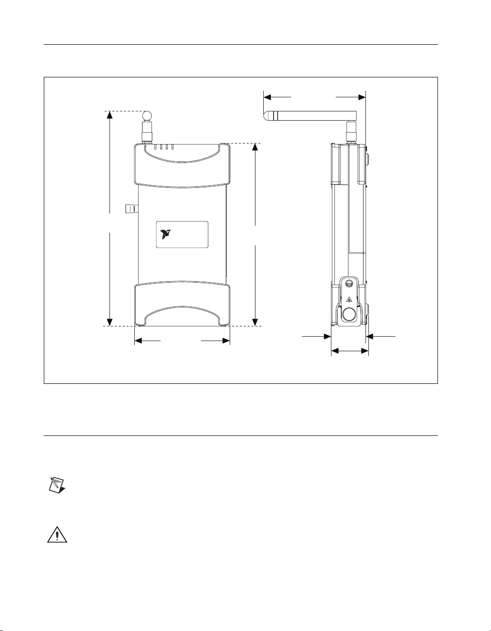
The NI WLS/ENET-9163 carrier combines with an NI C Series I/O module
to form an NI WLS/ENET-9000 Series device, as shown in Figure 1.
Note Only the NI WLS-9163 carrier comes with an antenna for wireless deployment.
NI C Series I/O Module
+
NI WLS/ENET-9163 Carrier
INSTRUMENTS
NATIONAL
LINK
WLS
IVE
ACT
K
TUS
LIN
STA
ER
S
L
E
W
IV
POW
INSTRUMENTS
NATIONAL
LINK
LS
W
ACTIVE
STATUS
ER
W
PO
1
R
P
D
N
G
T
E
S
E
R
LS-9163
S
W
C
g
I
0
1
R
N
P
.1
2
0
8
D
N
G
C
0
0
/1
0
V
1
V
0
9-3
T
X
U
A
P
T
M
C
IN
/A
W
K
.5
IN
4
L
=
K
LIN
S
L
E
W
IV
T
C
S
A
U
T
A
T
R
S
E
W
O
P
r
ie
rr
a
C
s
erie
NI WLS/ENET-9000 Series Device
VC
9
T
U
P
IN
W
.5
4
T
C
S
A
U
T
A
T
R
S
E
W
O
P
1
R
P
r
D
N
ie
G
T
rr
E
a
S
E
C
R
9163
ies
r
e
LS-
S
C
g
I W
0
1
R
N
P
.1
2
0
8
D
N
G
T
C
A
/
K
IN
L
V
0
-3
X
A
0
0
M
/1
0
1
Figure 1. NI WLS/ENET-9163 Carrier Forming the NI WLS/ENET-9000 Series Device
Throughout this manual, the combined NI WLS/ENET-9163 carrier and
C Series I/O module is referred to as the NI WLS/ENET-9000 Series
device.
Page 2
Dimensions
8.436 in.
(214.27 mm)
Figure 2 shows the NI WLS/ENET-9000 Series device dimensions.
4.012 in.
(101.90 mm)
WLS
LINK
ERROR
STATUS
PWR
NATIONAL
INSTRUMENTS
7.179 in.
(182.36 mm)
3.745 in.
(95.11 mm)
1.356 in.
(34.43 mm)
1.466 in.
(37.24 mm)
Figure 2. NI WLS/ENET-9000 Series Device Dimensions
Safety Guidelines
Operate the NI WLS/ENET-9000 Series device only as described in this
user guide.
Note Some C Series I/O modules may have more stringent certification standards than the
NI WLS/ENET-9163 carrier, and the combined system may be limited by individual
component restrictions.
Caution The NI WLS/ENET-9000 Series device is not certified for use in hazardous
locations.
NI WLS/ENET-9163 Carrier User Guide and Specifications 2 ni.com
Page 3

Hot Surface This icon denotes that the component may be hot. Touching this component
may result in bodily injury.
Safety Guidelines for Hazardous Voltages
If hazardous voltages are connected to the module, take the following
precautions. A hazardous voltage is a voltage greater than 42.4 V
60 VDC to earth ground.
Caution Ensure that hazardous voltage wiring is performed only by qualified personnel
adhering to local electrical standards.
Caution Do not mix hazardous voltage circuits and human-accessible circuits on the same
module.
Caution Make sure that the NI WLS/ENET-9163 carrier and circuits connected to the
module are properly insulated from human contact.
Caution The NI WLS/ENET-9163 carriers provide no isolation, but some modules offer
isolation. Follow the safety guidelines for each module when using hazardous voltage.
Related Documentation
Each application software package and driver includes information about
writing applications for taking measurements and controlling measurement
devices. Check
documentation, and refer to Table 1 for a list of locations for driver and
application software documentation. The document location references in
this table assume you have NI-DAQmx 8.8 or later, and where applicable,
version 7.1 or later of the NI application software.
ni.com/manuals for the most recent hardware
or
pk
© National Instruments Corporation 3 NI WLS/ENET-9163 Carrier User Guide and Specifications
Page 4

Table 1. NI Driver and Application Software Documentation
Software Document/Description Location/Topic
NI-DAQmx for
Windows
DAQ Getting Started
Guide—describes how to install
and use the NI-DAQmx driver
software for Windows and your
data acquisition (DAQ) device,
how to confirm the device is
operating properly, and how to
take an NI-DAQmx
measurement.
NI-DAQ Readme—includes
information about NI-DAQmx.
NI-DAQmx Help—explains how
to get started in your OS and
ADE; provides an NI-DAQmx
overview; includes information
about programming the most
common measurement tasks with
references to examples in CVI/C,
C++, .NET.
Start»Programs»National
Instruments»NI-DAQ»
DAQ Getting Started Guide
Start»Programs»National
Instruments»NI-DAQ»
NI-DAQ Readme
Start»Programs»National
Instruments»NI-DAQ»
NI-DAQmx Help
NI WLS/ENET-9163 Carrier User Guide and Specifications 4 ni.com
Page 5
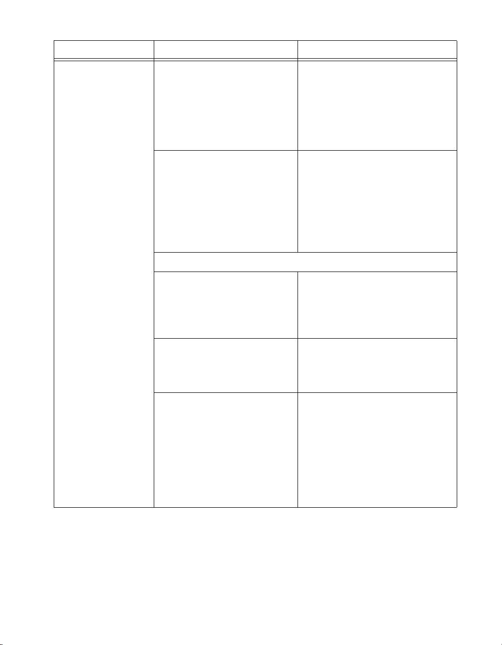
Table 1. NI Driver and Application Software Documentation (Continued)
Software Document/Description Location/Topic
LabVIEW Getting Started with
LabVIEW—describes the
LabVIEW graphical
programming environment and
the basic LabVIEW features you
use to build data acquisition and
instrument control application.
LabVIEW Help—provides
information about LabVIEW
programming concepts,
step-by-step instructions for
using LabVIEW, and reference
information about LabVIEW
VIs, functions, palettes, menus,
and tools.
LabVIEW Help Topics Specific to NI-DAQmx
Includes overview information
and a tutorial to learn how to take
an NI-DAQmx measurement in
LabVIEW using the DAQ
Assistant.
Describes the LabVIEW
NI-DAQmx VIs and properties.
Start»All Programs»National
Instruments»LabVIEW»
LabVIEW Manuals or navigate to
the
labview\manuals directory
and opening
LV_Getting_Started.pdf
Help»Search the LabVIEW Help
From the Contents tab, Getting
Started»Getting Started with DAQ
From the Contents tab,
VI and Function Reference»
Measurement I/O VIs and
Functions
Contains the conceptual and
how-to information you need
From the Contents tab, Taking
Measurements
to acquire and analyze
measurement data in LabVIEW,
including common
measurements, measurement
fundamentals, NI-DAQmx key
concepts, and device
considerations.
© National Instruments Corporation 5 NI WLS/ENET-9163 Carrier User Guide and Specifications
Page 6

Table 1. NI Driver and Application Software Documentation (Continued)
Software Document/Description Location/Topic
LabWindows™/CVI
™
LabWindows/CVI Help
Data Acquisition
book—contains NI-DAQmx
measurement concepts and
step-by-step instructions about
Help»Contents, then select Using
LabWindows/CVI»
Data Acquisition»Taking an
NI-DAQmx Measurement in
LabWindows/CVI
creating a measurement task
using the DAQ Assistant.
Measurement
Studio/Microsoft
Visual Studio .NET
ANSI C without
NI Application
Software
LabWindows/CVI Help
NI-DAQmx Library
LibraryReference»
NI-DAQmx Library
book—contains NI-DAQmx API
overviews and function
reference.
Microsoft Visual Studio .NET
Help/NI Measurement Studio
Help—contains NI-DAQmx
methods and properties.
Measurement Studio»
NI Measurement Studio Help and
select NI-DAQmx .NET Class
Library or NI-DAQmx Visual C++
Class Library
NI-DAQmx Help Start»All Programs»National
Instruments»NI-DAQ»
NI-DAQmx Help
NI-DAQmx C Reference
Help—describes the NI-DAQmx
Library functions.
Start»All Programs»National
Instruments»NI-DAQ»
NI-DAQmx C Reference Help
NI WLS/ENET-9163 Carrier User Guide and Specifications 6 ni.com
Page 7
Table 1. NI Driver and Application Software Documentation (Continued)
Software Document/Description Location/Topic
.NET Languages
without
NI Application
Software
*
NI-DAQmx .NET Help—contains
conceptual topics for using
NI-DAQmx with Visual C# and
Visual Basic .NET.
Start»All Programs»National
Instruments»NI-DAQ»
NI-DAQmx .NET Reference Help.
Expand NI Measurement Studio
Help»NI Measurement Studio
.NET Class Library»Reference to
view the function reference. Expand
NI Measurement Studio Help»
NI Measurement Studio .NET
Class Library»Using the
Measurement Studio .NET Class
Libraries
Visual Studio .NET
Help—contains conceptual topics
for using NI-DAQmx with Visual
C# and Visual Basic .NET.
Help»Contents. Select
Measurement Studio from the
Filtered By drop-down list and
follow the location instructions for
the NI-DAQmx .NET Help.
* With the Microsoft .NET Framework version 1.1 or later, you can use NI-DAQmx to create applications using Visual C#
and Visual Basic .NET without Measurement Studio. You need Microsoft Visual Studio .NET 2003 or Microsoft Visual
Studio 2005 for the API documentation to be installed.
Device Documentation and Specifications
Check ni.com/manuals for the most recent device and software
documentation. If you do not have Web access, NI-DAQmx includes a
Documentation CD that includes documentation available when
NI-DAQmx released.
Training Courses
If you need more help getting started developing an application with
NI products, NI offers training courses. To enroll in a course or obtain
a detailed course outline, refer to
ni.com/training.
Technical Support on the Web
For additional support, refer to ni.com/support or zone.ni.com.
© National Instruments Corporation 7 NI WLS/ENET-9163 Carrier User Guide and Specifications
Page 8
Installing the Software
NI WLS/ENET-9000 Series device software support for Windows
Vista/XP/2000 is provided by NI-DAQmx.
The DAQ Getting Started Guide, which is accessible from Start»
Programs»National Instruments»NI-DAQ or at
offers NI-DAQmx users step-by-step instructions for installing software
and hardware, configuring channels and tasks, and getting started
developing an application.
Installing Other Software
If you are using other software, refer to the installation instructions that
accompany your software.
Example Programs
The NI-DAQmx CD contains example programs that you can use to
get started programming with the NI WLS/ENET-9000 Series device.
Refer to the NI-DAQmx for WLS/ENET Devices Getting Started Guide that
shipped with your device, and is also accessible from Start»Programs»
National Instruments»NI-DAQ, for more information.
Using the NI WLS/ENET-9000 Series Device
ni.com/manuals,
Using the NI WLS/ENET-9000 Series Device on a Desktop
You can use the NI WLS/ENET-9000 Series device on a desktop. Figure 3
shows the stacking grooves for NI ENET-9000 Series devices, and where
to apply the rubber standoffs for the NI WLS/ENET-9000 devices. For
secure desktop use, you can adhere the supplied rubber standoffs to the
underside of the device.
Note NI ENET-9000 Series Only—the NI ENET-9000 Series device has underside
grooves that allow it to be stacked on top of other NI ENET-9000 Series devices.
Caution Do not stack an NI WLS-9000 Series device on top of an NI WLS-9000 Series
device.
Caution This transmitter must not be co-located or operated in conjunction with any other
antenna or transmitter.
NI WLS/ENET-9163 Carrier User Guide and Specifications 8 ni.com
Page 9
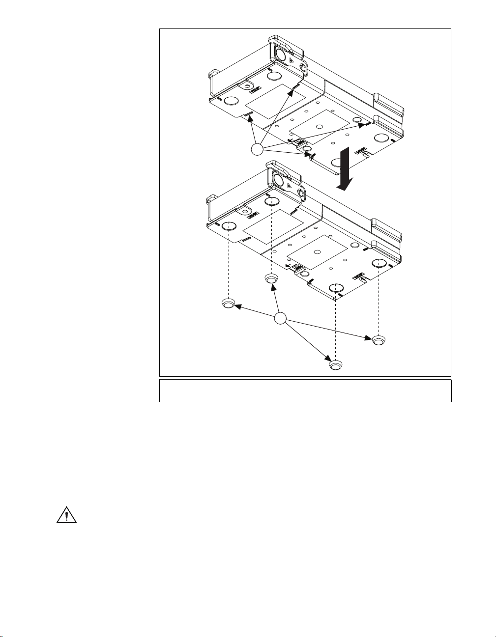
1
2
1 Stacking Grooves
(NI ENET-9000 Series Only)
Figure 3. Stacking Grooves and Rubber Standoffs for Desktop Use
2Rubber Standoffs
Mounting the NI WLS/ENET-9000 Series Device
You can mount the NI WLS/ENET-9000 Series device using a 75 mm
DIN-Rail kit or a panel mount kit. For kit accessory ordering information,
refer to the accessory section of the NI WLS/ENET-9163 product page at
ni.com.
Caution Your installation must meet the following requirements:
• Allows 25.4 mm (1 in.) of clearance above and below the NI WLS/ENET-9000 Series
device for air circulation.
• Allows 50.8 mm (2 in.) of clearance in front of modules for common connector
cabling, such as the 10-terminal detachable screw terminal connector.
© National Instruments Corporation 9 NI WLS/ENET-9163 Carrier User Guide and Specifications
Page 10
Attaching the NI 9910 DIN-Rail
NI WLS-9163
NI
WLS-9163
The NI 9910 DIN-Rail kit contains one clip for mounting the device on a
standard 35 mm DIN-Rail. To mount the device on a DIN-Rail, fasten the
DIN-Rail clip to the device using a number 2 Phillips screwdriver and
four M4 × 17 screws. The screws are included in the DIN-Rail kit. Make
sure the DIN-Rail kit is installed as illustrated in Figure 4, with the larger
lip of the DIN-RAIL positioned up. When the DIN-Rail kit is properly
installed, the NI WLS/ENET-9000 Series device is centered on the
DIN-Rail.
Caution Remove the C Series I/O module before mounting the carrier to the DIN-Rail.
IVE
WLS LINK
ACT
STATUS
POWE
r
ie
rr
a
C
s
T
ie
E
r
1
S
e
R
E
S
P
R
D
C
N
g
1
G
0
.1
R
2
NI WLS-9163
P
0
8
D
N
G
0
0
/1
0
1
C
V
V
T
30
X
C
A
/A
K
M
T 9
IN
U
L
W
P
IN
0.5
1
IVE
WLS LINK
ACT
STATUS
POWE
r
ie
rr
a
C
s
T
ie
E
r
1
S
e
R
E
P
S
R
D
C
N
g
1
G
0
.1
R
2
NI WLS-9163
P
0
8
D
N
G
0
0
/1
0
1
C
V
V
0
T
X
-3
A
/AC
K
M
T 9
IN
U
L
W
P
.5
IN
0
1
OR
Figure 4. NI WLS/ENET-9000 Series Device DIN-Rail Installation
NI WLS/ENET-9163 Carrier User Guide and Specifications 10 ni.com
Page 11
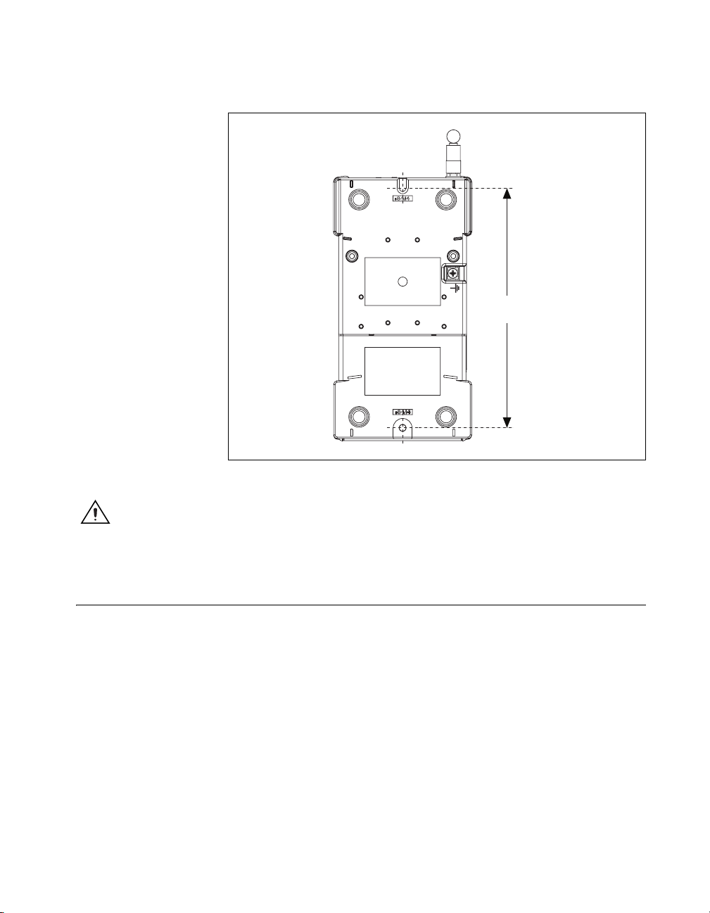
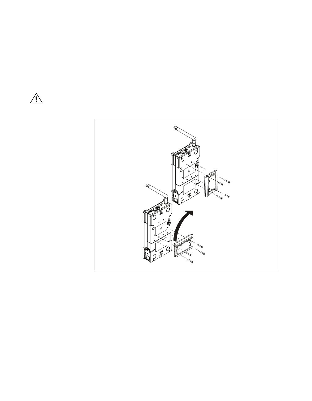
Mounting the NI WLS/ENET-9000 Series to a Panel
Thread inserts are located in the NI WLS/ENET-9000 Series device for
mounting it to a panel. Refer to Figure 5 for dimensions.
6.500 in.
(165.10 mm)
Figure 5. Device Panel Mounting Dimensions
Caution
you mount the carrier to the panel. After the NI WLS/ENET-9163 carrier is mounted, you
can reinsert the C Series module.
Remove the C Series I/O module from the NI WLS/ENET-9163 carrier before
Configuring the Ethernet Connection
You must have an Ethernet network in order to use the
NI WLS/ENET-9000 Series device. For more information about
configuring your Ethernet connection with the NI WLS/ENET-9000 Series
device, refer to the NI-DAQmx for WLS/ENET Devices Getting Started
Guide that shipped with your device. This document is also accessible from
Start»Programs»National Instruments»NI-DAQ.
© National Instruments Corporation 11 NI WLS/ENET-9163 Carrier User Guide and Specifications
Page 12

Setting Up the NI WLS/ENET-9000 Series Device
Complete the following steps to prepare the NI WLS/ENET-9000 Series
device for use:
1. Before connecting the hardware, install NI-DAQmx software,
LabVIEW SignalExpress, and the NI-DAQ Device Documentation
Browser. Refer to the DAQ Getting Started Guide for more
information about software installation.
Note The NI-DAQmx software is included on the CD shipped with your kit and is
available for download at
Documentation Browser is available from Start»Programs»National Instruments»
NI-DAQ»Browse Device Documentation. The DAQ Getting Started Guide is available
after installation from Start»Programs»National Instruments»NI-DAQ»DAQ Getting
Started Guide.
2. If you are not using any mounting accessories or stacking the devices,
3. Make sure the NI WLS/ENET-9000 Series device power is
4. Attach a ring lug, as shown in Figure 6, to a 14 AWG (1.6 mm) wire.
ni.com/support. After you install it, the NI-DAQ Device
attach the provided rubber standoffs to the bottom of the
NI WLS/ENET-9000 Series device, as described in the Using the
NI WLS/ENET-9000 Series Device on a Desktop section.
disconnected.
Connect the ring lug to the ground terminal on the bottom of the device
using the ground screw. Attach the other end of the wire to the system
ground.
NI WLS/ENET-9163 Carrier User Guide and Specifications 12 ni.com
Page 13

LINK
S
L
R
W
O
R
R
S
E
U
T
A
T
S
R
W
P
1
R
P
D
N
T
G
E
S
E
R
0
C Series Carrier
R
P
NI WLS-9163
802.11g
D
N
G
C
0
V
0
/1
0
1
0 V
9-3
T
U
X
A
T
M
INP
C
A
/
INK
4.5 W
L
1
1Ring Lug Attached to the Ground Screw
Figure 6. Ring Lug Attached to the Ground Screw
Note
Additionally, attach a wire with a ring lug to all other C Series I/O module cable
shields. You must connect this wire to the ground terminal of the device using the ground
screw. The ground terminal of the device should not be attached to the common terminal
on the C Series I/O module.
Connecting Power to the NI WLS/ENET-9000 Series Device
Power on the NI WLS/ENET-9000 Series device using the included power
adapter or other 9–30 VDC power source.
10/100BaseT(X) Ethernet Port Connection
Use the RJ45 port located on the NI WLS/ENET-9000 Series device
interface to connect the device to an Ethernet network. Use a standard
Category 5 (CAT-5) Ethernet cable (a shielded cable is recommended) to
connect the NI WLS/ENET-9000 Series device to an Ethernet hub, or use
an Ethernet crossover cable to connect the NI WLS/ENET-9000 Series
device directly to a computer.
Note Plug the standard Category 5 Ethernet cable into the RJ-45 Ethernet port on the
NI WLS-9000 Series device to configure the wireless network settings. After initial
configuration, you can remove the Ethernet cable from the NI WLS-9000 Series device
and use the device wireless capabilities.
© National Instruments Corporation 13 NI WLS/ENET-9163 Carrier User Guide and Specifications
Page 14

Device Interface
Figure 7 shows the NI WLS/ENET-9163 carrier interface.
Reset Button
1
VC
INPUT 9-30 V
4.5 W MAX
LINK/ACT
7
6
1 RJ-45 Ethernet Port
2LEDs: WLS LINK*, ACTIVE,
STATUS, and POWER
3 Reset Button
PFI1
GND
GND
10/100
4
5
2
WLS LINK
ACTIVE
STATUS
POWER
RESET
PFI0
NI WLS-9163
802.11g C Series Carrier
4 Trigger Connector
5 10/100 LED
6 LINK/ACT LED
7 Power Connector
3
* NI WLS-9163 Carrier Only.
Figure 7. NI WLS/ENET-9163 Carrier Interface
The NI WLS/ENET-9000 Series devices are equipped with a reset button
as shown in Figure 7.
Pressing the reset button results in the following device responses:
• When pressed for less than 5 seconds, the device reboots with the
current configuration.
• When pressed for 5 seconds or longer, the STATUS LED turns on.
When released, the device reboots into Factory Default Mode, which
returns the device user configuration to the factory-set defaults.
NI WLS/ENET-9163 Carrier User Guide and Specifications 14 ni.com
Page 15

LED Indicators
The LED indicators for the NI WLS/ENET-9000 Series device are listed in
Table 2.
Table 2. LED State/Device Status
LED Description Color LED State Device Status
10/100 Green On Connected at 100 Mbps
Off No Ethernet connection or 10 Mbps
connection
LINK/ACT Ye ll ow On Ethernet link
Off No Ethernet connection
Blinking Ethernet activity
POWER Green On Power on
Off Power off
STATUS Ye ll ow On Device firmware booting or
resetting to factory default
Off Normal operation
1 Blink No C Series module detected
2 Blinks Firmware/FPGA image corrupted,
update firmware through MAX
3 Blinks Firmware error, reboot
ACTIVE Green On A DAQ task is running on the
device
Off Device available
WLS LINK* Green On Connected and authenticated
Off Not connected to access point
* NI WLS-9163 Only
© National Instruments Corporation 15 NI WLS/ENET-9163 Carrier User Guide and Specifications
Page 16

Pinouts
Trigger Connector
Cabling
GND
GND
Figure 8. Trigger Connector Pinout
Table 3 shows the standard Ethernet cable wiring connections for both
normal and crossover cables.
Table 3. Ethernet Cable Wiring Connections
Connector 2
Pin Connector 1
1 white/orange white/orange white/green
2 orange orange green
3 white/green white/green white/orange
4 blue blue blue
(Normal)
PFI 1
PFI 0
Connector 2
(Crossover)
5 white/blue white/blue white/blue
6 green green orange
7 white/brown white/brown white/brown
8 brown brown brown
NI WLS/ENET-9163 Carrier User Guide and Specifications 16 ni.com
Page 17

Connector 1 Connector 2
Pin 1
Figure 9. Ethernet Connector Pinout
Pin 1 Pin 8Pin 8
Using the NI WLS/ENET-9000 Series Device
C Series I/0 Modules
National Instruments C Series I/O modules provide built-in signal
conditioning and screw terminal, spring terminal, BNC, D-SUB, or
RJ-50 connectors. A wide variety of I/O types are available, allowing
you to customize the your system to meet your application needs.
You can swap C Series modules when the NI WLS/ENET-9163 carrier is
plugged in. After swapping modules, even if it is the same module type, you
must discover the device through MAX again.
Because the modules contain built-in signal conditioning for extended
voltage ranges or industrial signal types, you can make your
wiring connections directly from the C Series I/O modules to your
sensors/actuators. In most cases, the C Series I/O modules provide isolation
from channel-to-earth ground.
AI Sample Timing
The NI WLS/ENET-9000 Series device contains an advanced analog input
timing engine. Timing and synchronization signals are available through
the PFI lines. Refer to the Analog Input Timing Signal section for more
information about the configuration of these signals.
© National Instruments Corporation 17 NI WLS/ENET-9163 Carrier User Guide and Specifications
Page 18

Analog Input
To perform analog input measurements, insert a supported analog input
C Series I/O module into the NI WLS/ENET-9163 carrier. The
measurement specifications, such as number of channels, channel
configuration, sample rate, and gain, are determined by the type of C Series
I/O module used. For more information and wiring diagrams, refer to the
documentation included with your C Series I/O modules.
Analog Input Triggering
A trigger is a signal that causes an action, such as starting or stopping the
acquisition of data. When you configure a trigger, you must decide how
you want to produce the trigger and the action you want the trigger to cause.
The NI WLS/ENET-9000 Series device supports internal software
triggering and external digital triggering.
Three triggers are available: AI Start Trigger Signal, AI Reference Trigger
Signal, and AI Pause Trigger Signal.
AI Start Trigger Signal
Use the AI Start Trigger (ai/StartTrigger) signal to begin a measurement
acquisition. A measurement acquisition consists of one or more samples. If
you do not use triggers, begin a measurement with a software command.
Once the acquisition begins, configure the acquisition to stop in one of the
following ways:
• When a certain number of points is sampled (in finite mode)
• With a software command (in continuous mode)
An acquisition that uses a start trigger is sometimes referred to as a
posttriggered acquisition. That is, samples are measured only after the
trigger.
Using a Digital Source
To use ai/StartTrigger with a digital source, specify a source and an edge.
NI-DAQmx can provide an internal start trigger or PFI 0 may be used.
Refer to the Device Routing in MAX topic in the NI-DAQmx Help or the
LabVIEW Help in version 8.0 or later for more information.
NI WLS/ENET-9163 Carrier User Guide and Specifications 18 ni.com
Page 19

The NI-DAQmx Help is available after installation from Start» Programs»
National Instruments»NI-DAQ»NI-DAQmx Help. To view the
LabVIEW Help, in version 8.0 or later, select Help»Search the LabVIEW
Help in LabVIEW. Alternately, to download the LabVIEW Help, go to
ni.com/manuals.
You also can specify whether the measurement acquisition begins on the
rising edge or falling edge of ai/StartTrigger.
Routing AI Start Trigger to an Output Terminal
You can route ai/StartTrigger to the PFI 0 terminal. The output polarity is
selectable.
AI Reference Trigger Signal
Use a reference trigger (ai/ReferenceTrigger) signal to stop a measurement
acquisition. To use a reference trigger, specify a buffer of finite size and
a number of pretrigger samples (samples that occur before the reference
trigger). The number of posttrigger samples (samples that occur after the
reference trigger) desired is the buffer size minus the number of pretrigger
samples.
When the acquisition begins, the NI WLS/ENET-9000 Series device begins
to fill the buffer. After the specified number of pretrigger samples are
captured, the NI WLS/ENET-9000 Series device begins to look for the
reference trigger condition. If the reference trigger condition occurs before
the NI WLS/ENET-9000 Series device captures the specified number of
pretrigger samples, the NI WLS/ENET-9000 Series device ignores the
condition.
If the buffer becomes full, the NI WLS/ENET-9000 Series device
continuously discards the oldest samples in the buffer to make space for
the next sample. This data can be accessed with some limitations before
the NI WLS/ENET-9000 Series device discards it. Refer to the
KnowledgeBase document, Can a Pretriggered Acquisition be
Continuous?, for more information. To access this KnowledgeBase, go to
ni.com/info and enter the info code rdcanq.
© National Instruments Corporation 19 NI WLS/ENET-9163 Carrier User Guide and Specifications
Page 20

When the reference trigger occurs, the NI WLS/NET-9163 Series device
continues to write samples to the buffer until the buffer contains the number
of posttrigger samples desired. Figure 10 shows the final buffer.
Reference Trigger
Pretrigger Samples
Complete Buffer
Figure 10. Reference Trigger Final Buffer
Posttrigger Samples
Using a Digital Source
To use ai/ReferenceTrigger with a digital source, specify a source and an
edge. PFI 0 can provide the source. Refer to the Device Routing in MAX
topic in the NI-DAQmx Help or the LabVIEW Help in version 8.0 or later
for more information.
The NI-DAQmx Help is available after installation from Start»Programs»
National Instruments»NI-DAQ»NI-DAQmx Help. To view the
LabVIEW Help, in version 8.0 or later, select Help»Search the LabVIEW
Help in LabVIEW. Alternately, to download the LabVIEW Help, go to
ni.com/manuals.
You also can specify whether the measurement acquisition stops on the
rising edge or falling edge of ai/ReferenceTrigger.
AI Pause Trigger Signal
The Pause Trigger signal can be generated from external sources. Any time
the signal deasserts, you can use the Pause Trigger signal to pause the
acquisition.
You can use the AI Pause Trigger (ai/PauseTrigger) signal to pause and
resume a measurement acquisition. The internal sample clock pauses while
the external trigger signal is active and resumes when the signal is inactive.
You can program the active level of the pause trigger to be high or low.
Using a Digital Source
To use ai/PauseTrigger, specify a source and a polarity on PFI 0.
NI WLS/ENET-9163 Carrier User Guide and Specifications 20 ni.com
Page 21

Note Pause triggers are only sensitive to the level of the source, not the edge.
Analog Input Timing Signal
AI Sample Clock
A sample consists of one reading from each channel in the AI task.
ai/SampleClock signals the start of a sample of all analog input channels
in the task. ai/SampleClock can be generated from external or internal
sources.
Using A Digital Source
To use ai/SampleClock, specify a source and an edge on PFI 1. For more
information, refer to the Device Routing in MAX topic in the NI-DAQmx
Help.
PFI
Sigma-Delta Module Internal Output
ai/SampleClock Timebase
20 MHz Timebase
Programmable
Clock
Divider
Figure 11. Sample Clock Timing Options
Routing AI Sample Clock to an Output Terminal
You can route ai/SampleClock to the PFI 1 terminal.
Convert Behavior For Analog Input Modules
Scanned
Scanned C Series analog input modules contain a single A/D converter and
a multiplexer to select between multiple input channels. When the C Series
Module Interface receives a Sample Clock pulse, it begins generating a
Convert Clock for each scanned module in the current task. Each Convert
Clock signals the acquisition of a single channel from that module. The
Convert Clock rate depends on the module being used, the number of
channels, and the Sample Clock rate.
ai/SampleClock
© National Instruments Corporation 21 NI WLS/ENET-9163 Carrier User Guide and Specifications
Page 22

Simultaneous Sample-and-Hold
Simultaneous sample-and-hold (SSH) C Series analog input modules
contain multiple A/D converters or circuitry that allows all the input
channels to be sampled at the same time. These modules sample their
inputs on every AI Sample Clock pulse.
Sigma-Delta
Sigma-Delta C Series analog input modules function much like SSH
modules, but use A/D converters that require a high-frequency oversample
clock to produce accurate, synchronized data.
This clock is used as the AI Sample Clock Timebase. While most modules
supply a common oversample clock frequency (12.8 MHz), some modules,
such as the NI 9234, supply a different frequency. The sampling
is an integer divisor of the frequency of the AI Sample Clock Timebase.
Getting Started with AI Applications in Software
You can use the NI WLS/ENET-9000 Series device in the following analog
input applications:
• Single-Point
•Finite
• Continuous
For more information about programming analog input applications and
triggers in software, Refer to the NI-DAQmx Help or the LabVIEW Help in
version 8.0 or later for more information.
The NI-DAQmx Help is available after installation from Start»Programs»
National Instruments»NI-DAQ»NI-DAQmx Help. To view the
LabVIEW Help, in version 8.0 or later, select Help»Search the LabVIEW
Help in LabVIEW. Alternately, to download the LabVIEW Help, go to
ni.com/manuals.
NI WLS/ENET-9163 Carrier User Guide and Specifications 22 ni.com
Page 23

Specifications
Note These specifications are for the NI WLS/ENET-9163 carrier only, unless otherwise
noted.
Analog Input
These specifications are typical at 25 °C unless otherwise noted.
For C Series I/O module specifications, refer to the documentation
included with the modules.
Input FIFO size ...................................... 4095 samples >16 bit
8191 samples ≤16 bit
Digital Triggers
Sample rate
1
NI WLS/ENET-9163 carrier........... 5 MS/s (multi-channel,
aggregate), maximum
With NI WLS/ENET-9215 ............. 100 kS/s, maximum
Timing accuracy
Timing resolution
2
................................... 50 ppm of sample rate
2
................................. 50 ns
Number of channels supported .............. Determined by the C Series
I/O module
Static Characteristics
Number of terminals .............................. 2 bi-directional, individually
settable
Pull-down resistor .................................. 49.9 kΩ ±0.5%
Input voltage protection
Power–on state ....................................... Input
Required minimum input pulse width.... 100 ns
3
........................ ±20 V on each pin
1
Performance dependent on type of installed C Series I/O modules and number of channels in the task.
2
Does not include group delay. Refer to C Series I/O module documentation for more information.
3
Stresses beyond those listed under Input voltage protection may cause permanent damage to the device.
© National Instruments Corporation 23 NI WLS/ENET-9163 Carrier User Guide and Specifications
Page 24

PFI Functionality
PFI 1 .......................................................Sample Clock In,
Sample Clock Out
PFI 0 .......................................................Start Trigger In, Start Trigger
Out, Pause In, Reference
Trigger In
Maximum Operation Conditions
Level Min Max
IOL output low current — 8 mA
IOH output high current — –8 mA
Digital Input Characteristics
Level Min Max
1
VIL input low voltage
V
input high voltage
IH
IIL input low current (Vin=0V)
I
input high current (Vin=5V)
IH
Digital Output Characteristics
Parameter Vol t a g e L e ve l Current Level
V
OL
V
OH
Wireless (NI WLS-9163 Carrier Only)
Radio mode.............................................IEEE 802.11b, 802.11g
Wireless mode ........................................Ad-Hoc and Infrastructure
Frequency range .....................................2.412–2.462 GHz
Channel
2
..................................................1–14
0 V
2 V
—
—
0.5 V 6 mA
4.0 V –6 mA
0.8 V
5 V
–15 μA
120 μA
1
Module-dependent.
2
Due to regulations, the valid channels depend upon in which country the device is operating.
NI WLS/ENET-9163 Carrier User Guide and Specifications 24 ni.com
Page 25

Security...................................................WEP-40, WEP-104, WPA,
WPA2
EAP Type .................................LEAP, PEAP
1
, TTLS2, TLS
Center frequency
11b ...................................................2412–2484 MHz
11g ...................................................2412–2472 MHz
Channel interval
11b ...................................................5 MHz
11g ...................................................5 MHz
Modulation type
11g ...................................................OFDM-CCK (64QAM, 16QAM,
QPSK, BPSK)
11b ...................................................DSSS (CCK, DQPSK, DBPSK)
TX power
Maximum Radio
Specification Channel
Output
11g 1 12 dBm
2 16 dBm
3, 4 15.5 dBm
5–7 15 dBm
8–10 14.5 dBm
11–13 14 dBm
11b 1–14 16 dBm
Receiver Sensitivity
11b, FER<8%
11 Mbps...........................................–82 dB/min
5.5 Mbps ..........................................–84 dB/min
2 Mbps .............................................–86 dB/min
1 Mbps .............................................–88 dB/min
1
Only PEAPv0/MS-CHAPv2 is supported.
2
Only CHAP and MS-CHAPv2 are supported.
NI WLS/ENET-9163 Carrier User Guide and Specifications 25 ni.com
Page 26

11g, PER<10%
54 Mbps...........................................–68 dB/min
48 Mbps...........................................–68 dB/min
36 Mbps...........................................–75 dB/min
24 Mbps...........................................–79 dB/min
18 Mbps...........................................–82 dB/min
12 Mbps...........................................–84 dB/min
9 Mbps .............................................–87 dB/min
6 Mbps .............................................–88 dB/min
Antenna (NI WLS-9163 Carrier Only)
Connector................................................Female RP-SMA connector
Electrical performance
Property Performance
VSWR Max. 2.0
Impedance 50 Ω nominal
Directivity Omni
(2.4–2.5 GHz)
Max. gain 2.0 dBi
(2.4–2.5 GHz)
Ethernet
Network interface ...................................100 Base-TX, full-duplex;
100 Base-TX, half-duplex;
10 Base-T, full-duplex;
10 Base-T, half-duplex
Network protocols ..................................TCP/IP, UDP
Network ports used.................................HTTP:80 (configuration only),
HTTPS:43 (configuration only),
TCP:31415, UDP:44515
Network IP configuration .......................DHCP + Link–Local, DHCP,
Static, Link–Local
Communication rates..............................10/100 Mbps, auto-negotiated
Maximum cabling distance.....................100 m/segment
NI WLS/ENET-9163 Carrier User Guide and Specifications 26 ni.com
Page 27

Module I/O States
At power-on ...........................................Module-dependent. Refer to the
Power Requirements
Caution You must use a National Electric Code (NEC) UL Listed Class 2 power supply
with NI WLS/ENET-9000 Series devices.
Note Some C Series I/O modules have additional power requirements. For more
information about the C Series I/O module power requirements, refer to the documentation
included with the C Series I/O module.
Input voltage range.................................9 V to 30 V
Maximum required input power ............ 4.5 W
Power input mating connector ............... 2 position combicon, Phoenix
Physical Characteristics
Weight.................................................... Approx. 242 g (8.5 oz)
documentation included with the
C Series I/O module.
Contact part number: 1714977
Weight with antenna
(NI WLS-9163 Only) ............................. Approx. 256 g (9 oz)
Dimensions............................................. 182 mm × 95 mm × 37 mm
(7.18 in. × 3.75 in. × 1.50 in.)
With rubber feet attached....................... +3.56 mm (+0.140 in.)
Antenna
Antenna connector
(antenna not attached) ............................ +5.71 mm (+0.225 in.)
Attached, fully extended ........................ +108.7 mm (+4.28 in.)
Note Refer to the Dimensions section for device dimensions with the antenna attached.
© National Instruments Corporation 27 NI WLS/ENET-9163 Carrier User Guide and Specifications
Page 28

Safety Standards
Note For UL and other safety certifications, refer to the product label, or go to ni.com/
certification
in the Certification column.
If you need to clean the carrier, wipe it with a dry towel.
The NI WLS/ENET-9163 carrier is designed to meet the requirements of
the following standards of safety for electrical equipment for measurement,
control, and laboratory use:
• IEC 61010-1, EN 61010-1
• UL 61010-1, CSA 61010-1
• EN 50371
1
, search by model number or product line, and click the appropriate link
1
Safety Voltages
Connect only voltages that are within these limits.
V terminal to C terminal.........................30 V max, Measurement
Category I
Measurement Category I is for measurements performed on circuits not
directly connected to the electrical distribution system referred to as
MAINS voltage. MAINS is a hazardous live electrical supply system that
powers equipment. This category is for measurements of voltages from
specially protected secondary circuits. Such voltage measurements include
signal levels, special equipment, limited-energy parts of equipment,
circuits powered by regulated low-voltage sources, and electronics.
Caution Do not connect the system to signals or use for measurements within
Measurement Categories II, III, or IV.
RF Safety Warning (NI WLS-9163 Carrier Only)
This equipment complies with FCC radiation exposure limits set for
uncontrolled equipment and meets the FCC radio frequency (RF) Exposure
Guidelines in Supplement C to OET65. This product generates and radiates
radio frequency energy. To comply with the radio frequency radiation
exposure guidelines in an uncontrolled environment, this equipment should
be installed and operated with at least 20 cm and more between the radiator
and the person’s body (excluding extremities: hands, wrists, feet, and legs).
1
NI WLS-9163 carrier only.
NI WLS/ENET-9163 Carrier User Guide and Specifications 28 ni.com
Page 29

Environmental
Shock and Vibration
The NI WLS/ENET-9163 carrier is intended for indoor use only. For
outdoor use, mount the system in a suitably rated enclosure.
Operating temperature
(IEC-60068-2-1 and IEC-60068-2-2) .... 0 to 55 °C
Storage temperature
(IEC-60068-2-1 and IEC-60068-2-2) .... –10 to 70 °C
Ingress protection................................... IP 30
Operating humidity
(IEC-60068-2-56)................................... 10 to 90% RH, noncondensing
Storage humidity (IEC-60068-2-56) ...... 5 to 90% RH, noncondensing
Maximum altitude .................................. 2,000 m
Pollution Degree (IEC 60664) ............... 2
To meet these specifications, you must panel mount the
NI WLS/ENET-9163 carrier and affix ferrules to the ends of the terminal
lines.
Operational shock .................................. 30 g peak, half-sine, 11 ms pulse
(Tested in accordance with
IEC-60068-2-27. Test profile
developed in accordance with
MIL-PRF-28800F.)
Random vibration
Operating ........................................ 5 to 500 Hz, 0.3 g
Nonoperating .................................. 5 to 500 Hz, 2.4 g
(Tested in accordance
with IEC-60068-2-64.
Nonoperating test profile
exceeds the requirements of
MIL-PRF-28800F, Class 3.)
© National Instruments Corporation 29 NI WLS/ENET-9163 Carrier User Guide and Specifications
rms
rms
Page 30

Electromagnetic Compatibility
This product is designed to meet the requirements of the following
standards of EMC for electrical equipment for measurement, control,
and laboratory use:
• EN 61326 EMC requirements; Minimum Immunity
• EN 55011 Emissions; Group 1, Class A
• CE, C-Tick, ICES, and FCC Part 15 Emissions; Class A
• EN 301489-01
•FCC 15-2471, IC RSS-2101, EN 300328
Note For EMC compliance, operate this device according to product documentation. For
country-specific restrictions, go to
product line, and click the appropriate link in the Certification column
Electronic Compatibility Information
This hardware has been tested and found to comply with the applicable
regulatory requirements and limits for electromagnetic compatibility
(EMC) as indicated in the hardware’s Declaration of Conformity (DoC).
These requirements and limits are designed to provide reasonable
protection against harmful interference when the hardware is operated in
the indicated electromagnetic environment. In special cases, for example
when either highly sensitive or noisy hardware is being used in close
proximity, additional mitigation measures may have to be employed to
minimize the potential for electromagnetic interference.
1
, EN 301489-17
ni.com/certification, search by model number or
1
1
While this hardware is compliant with the applicable regulatory EMC
requirements, there is no guarantee that interference will not occur in a
particular installation. To minimize the potential for the hardware to cause
interference to radio and television reception or to experience unacceptable
performance degradation, install and use this hardware in strict accordance
with the instructions in the hardware documentation and the DoC.
If this hardware does cause interference with licensed radio
communications services or other nearby electronic hardware, which can
be determined by turning the hardware off and on, you are encouraged to
try to correct the interference by one or more of the following measures:
• Reorient the antenna of the receiver (the device suffering interference).
• Relocate the transmitter (the device generating interference) with
respect to the receiver.
1
NI WLS-9163 carrier only.
NI WLS/ENET-9163 Carrier User Guide and Specifications 30 ni.com
Page 31

CE Compliance
• Plug the transmitter into a different outlet so that the transmitter and
the receiver are on different branch circuits.
This hardware may generate emissions that exceed regulatory requirements
or may become more sensitive to disturbances in the local electromagnetic
environment when test leads are attached or when connected to a test
object.
Operation of this hardware in a residential area is likely to cause harmful
interference. Users are required to correct the interference at their own
expense or cease operation of the hardware.
Changes or modifications not expressly approved by National Instruments
could void the user’s authority to operate the hardware under the local
regulatory rules.
This product meets the essential requirements of applicable European
Directives, as amended for CE marking, as follows:
• 2006/95/EC; Low-Voltage Directive (safety)
• 2004/108/EC; Electromagnetic Compatibility (EMC) Directive
• 1999/5/EC
1
; Radio and Telecommunications Terminal Equipment
(R&TTE) Directive
EU Regulatory Statements
Česky
[Czech]
Dansk
[Danish]
Deutsch
[German]
Eesti
[Estonian]
English Hereby, National Instruments, declares that this NI WLS/ENET-9163 is in compliance with
Español
[Spanish]
© National Instruments Corporation 31 NI WLS/ENET-9163 Carrier User Guide and Specifications
National Instruments tímto prohlašuje, _e tento NI WLS/ENET-9163 je ve shodě se
základními po_adavky a dalšími příslušnými ustanoveními směrnice 1999/5/ES.
Undertegnede National Instruments erklćrer herved, at fřlgende udstyr
NI WLS/ENET-9163 overholder de vćsentlige krav og řvrige relevante krav i direktiv
1999/5/EF.
Hiermit erklärt National Instruments, dass sich das Gerät NI WLS/ENET-9163 in
Übereinstimmung mit den grundlegenden Anforderungen und den übrigen einschlägigen
Bestimmungen der Richtlinie 1999/5/EG befindet.
Käesolevaga kinnitabNational Instruments seadme NI WLS/ENET-9163 vastavust
direktiivi 1999/5/EÜ põhinõuetele ja nimetatud direktiivist tulenevatele teistele
asjakohastele sätetele.
the essential requirements and other relevant provisions of Directive 1999/5/EC.
Por medio de la presente National Instruments declara que el NI WLS/ENET-9163 cumple
con los requisitos esenciales y cualesquiera otras disposiciones aplicables o exigibles de
la Directiva 1999/5/CE.
Page 32

Ελληνική
[Greek]
Français
[French]
Italiano
[Italian]
Latviski
[Latvian]
Lietuvių
[Lithuanian]
Nederlands
[Dutch]
ΜΕ ΤΗΝ ΠΑΡΟΥΣΑ National Instruments ΔΗΛΩΝΕΙ ΟΤΙ NI WLS/ENET-9163
ΣΥΜΜΟΡΦΩΝΕΤΑΙ ΠΡΟΣ ΤΙΣ ΟΥΣΙΩΔΕΙΣ ΑΠΑΙΤΗΣΕΙΣ ΚΑΙ ΤΙΣ ΛΟΙΠΕΣ ΣΧΕΤΙΚΕΣ
ΔΙΑΤΑΞΕΙΣ ΤΗΣ ΟΔΗΓΙΑΣ 1999/5/ΕΚ.
Par la présente National Instruments déclare que l'appareil NI WLS/ENET-9163 est
conforme aux exigences essentielles et aux autres dispositions pertinentes de la directive
1999/5/CE.
Con la presente National Instruments dichiara che questo NI WLS/ENET-9163 è conforme
ai requisiti essenziali ed alle altre disposizioni pertinenti stabilite dalla direttiva 1999/5/CE.
Ar šo National Instruments deklarē, ka NI WLS/ENET-9163 atbilst Direktīvas 1999/5/EK
būtiskajām prasībām un citiem ar to saistītajiem noteikumiem.
Šiuo National Instruments deklaruoja, kad šis NI WLS/ENET-9163 atitinka esminius
reikalavimus ir kitas 1999/5/EB Direktyvos nuostatas.
Hierbij verklaart National Instruments dat het toestel NI WLS/ENET-9163 in
overeenstemming is met de essentiële eisen en de andere relevante bepalingen van
richtlijn 1999/5/EG.
Malti
[Maltese]
Magyar
[Hungarian]
Polski
[Polish]
Português
[Portuguese]
Slovensko
[Slovenian]
Slovensky
[Slovak]
Suomi
[Finnish]
Svenska
[Swedish]
Íslenska
[Icelandic]
Norsk
[Norwegian]
Hawnhekk, National Instruments, jiddikjara li dan NI WLS/ENET-9163 jikkonforma
mal-htigijiet essenzjali u ma provvedimenti ohrajn relevanti li hemm fid-Dirrettiva
1999/5/EC.
Alulírott, National Instruments nyilatkozom, hogy a NI WLS/ENET-9163 megfelel a
vonatkozó alapvetõ követelményeknek és az 1999/5/EC irányelv egyéb elõírásainak.
Niniejszym National Instruments. oświadcza, że NI WLS/ENET-9163 jest zgodny z
zasadniczymi wymogami oraz pozostałymi stosownymi postanowieniami Dyrektywy
1999/5/EC.
National Instruments declara que este NI WLS/ENET-9163 está conforme com os
requisitos essenciais e outras disposições da Directiva 1999/5/CE.
National Instruments izjavlja, da je ta NI WLS/ENET-9163 v skladu z bistvenimi zahtevami
in ostalimi relevantnimi določili direktive 1999/5/ES.
National Instruments týmto vyhlasuje, _e NI WLS/ENET-9163 spĺňa základné po_iadavky
a všetky príslušné ustanovenia Smernice 1999/5/ES.
National Instruments vakuuttaa täten että NI WLS/ENET-9163 tyyppinen laite on direktiivin
1999/5/EY oleellisten vaatimusten ja sitä koskevien direktiivin muiden ehtojen mukainen.
Härmed intygar National Instruments att denna NI WLS/ENET-9163 står I
överensstämmelse med de väsentliga egenskapskrav och övriga relevanta bestämmelser
som framgår av direktiv 1999/5/EG.
Hér með lýsir National Instruments yfir því að NI WLS/ENET-9163 er í samræmi við
grunnkröfur og aðrar kröfur, sem gerðar eru í tilskipun 1999/5/EC.
National Instruments erklærer herved at utstyret NI WLS/ENET-9163 er i samsvar med de
grunnleggende krav og øvrige relevante krav i direktiv 1999/5/EF.
Note Refer to the Declaration of Conformity (DoC) for this product for any additional
regulatory compliance information. To obtain the DoC for this product, visit
certification
, search by model number or product line, and click the appropriate link
ni.com/
in the Certification column.
NI WLS/ENET-9163 Carrier User Guide and Specifications 32 ni.com
Page 33

Environmental Management
⬉ᄤֵᙃѻક∵ᶧࠊㅵ⧚ࡲ⊩ ˄Ё
˅
Ёᅶ᠋
National Instruments is committed to designing and manufacturing
products in an environmentally responsible manner. NI recognizes that
eliminating certain hazardous substances from our products is beneficial
not only to the environment but also to NI customers.
For additional environmental information, refer to the NI and the
Environment Web page at
environmental regulations and directives with which NI complies, as well
as other environmental information not included in this document.
Waste Electrical and Electronic Equipment (WEEE)
EU Customers At the end of their life cycle, all products must be sent to a WEEE recycling
center. For more information about WEEE recycling centers and National Instruments
WEEE initiatives, visit
National Instruments
݇Ѣ
National Instruments
(For information about China RoHS compliance, go to
ni.com/environment/weee.htm.
Ё
ni.com/environment. This page contains the
RoHS
ヺড়Ё⬉ᄤֵᙃѻકЁ䰤ࠊՓ⫼ᶤѯ᳝ᆇ⠽䋼ᣛҸ
ড়㾘ᗻֵᙃˈ䇋ⱏᔩ
RoHS
ni.com/environment/rohs_china
ni.com/environment/rohs_china
(RoHS)
DŽ
DŽ
.)
© National Instruments Corporation 33 NI WLS/ENET-9163 Carrier User Guide and Specifications
Page 34

Regulatory Information
United States
This product generates and radiates radio frequency energy. To comply
with the radio frequency radiation exposure guidelines in an uncontrolled
environment, this equipment must be installed and operated while
maintaining a minimum body-to-antenna distance of 20 cm.
This product complies with Part 15 of the FCC Rules. Operation is subject
to these two conditions: (1) this device may not cause harmful interference,
and (2) this device must accept any interference received, including
interference that may cause undesired operation.
This product does not contain any user serviceable components. Any
unauthorized product changes or modifications will invalidate the warranty
and all applicable regulatory certifications and approvals.
Canada
This product complies with Industry Canada RSS-210.
Cet appareil est conforme aux norme RSS210 d'Industrie Canada.
1
Europe—EU Declaration of Conformity
Marking by the above CE symbol on the label indicates compliance with
the Essential Requirements of the R&TTE Directive of the European Union
(1999/5/EC). This equipment meets the following conformance standards:
EN 300 893, EN300 328, EN301 489-17, EN60950.
1
NI WLS-9163 only.
NI WLS/ENET-9163 Carrier User Guide and Specifications 34 ni.com
Page 35

Europe – Restrictions for Use of 2.4 GHz Frequencies in European
Community Countries
België/
Belgique:
Deutschland: License required for outdoor installations. Check with reseller for procedure to follow.
France: Restricted frequency band: only channels 1 to 7 (2400 MHz and 2454 MHz respectively) may be used
Italia: License required for indoor use. Use with outdoor installations not allowed.
Nederland: License required for outdoor installations. Check with reseller for procedure to follow.
For private usage outside buildings across public grounds over less than 300m no special registration
with IBPT/BIPT is required. Registration to IBPT/BIPT is required for private usage outside buildings
across public grounds over more than 300m. For registration and license please contact IBPT/BIPT.
Voor privé-gebruik buiten gebouw over publieke groud over afstand kleiner dan 300m geen registratie
bij BIPT/IBPT nodig; voor gebruik over afstand groter dan 300m is wel registratie bij BIPT/IBPT
nodig. Voor registratie of licentie kunt u contact opnemen met BIPT.
Dans le cas d'une utilisation privée, à l'extérieur d'un bâtiment, au-dessus d'un espace public, aucun
enregistrement n'est nécessaire pour une distance de moins de 300m. Pour une distance supérieure à
300m un enregistrement auprès de I'IBPT est requise. Pour les enregistrements et licences, veuillez
contacter I'IBPT.
Anmeldung im Outdoor-Bereich notwendig, aber nicht genehmigungspflichtig.Bitte mit Händler die
Vorgehensweise abstimmen.
outdoors in France.
Bande de fréquence restreinte : seuls les canaux 1- 7 (2400 et 2454 MHz respectivement) doivent être
utilisés endroits extérieur en France. Vous pouvez contacter I'Autorité de Régulation des
Télécommuniations (http://www.art-telecom.fr) pour la procédure à suivre.
E'necessaria la concessione ministeriale anche per l'uso interno.
Verificare con i rivenditori la procedura da seguire.
Licentie verplicht voor gebruik met buitenantennes. Neem contact op met verkoper voor juiste
procedure.
Japan
The certified radio equipment is embedded in this device.
本機器には認証済み無線設備が内蔵されています
© National Instruments Corporation 35 NI WLS/ENET-9163 Carrier User Guide and Specifications
Page 36

Where to Go for Support
National Instruments corporate headquarters is located at
11500 North Mopac Expressway, Austin, Texas, 78759-3504.
National Instruments also has offices located around the world to help
address your support needs. For telephone support in the United States,
create your service request at
instructions or dial 512 795 8248. For telephone support outside the United
States, contact your local branch office:
Australia 1800 300 800, Austria 43 662 457990-0,
Belgium 32 (0) 2 757 0020, Brazil 55 11 3262 3599,
Canada 800 433 3488, China 86 21 5050 9800,
Czech Republic 420 224 235 774, Denmark 45 45 76 26 00,
Finland 358 (0) 9 725 72511, France 01 57 66 24 24,
Germany 49 89 7413130, India 91 80 41190000, Israel 972 3 6393737,
Italy 39 02 41309277, Japan 0120-527196, Korea 82 02 3451 3400,
Lebanon 961 (0) 1 33 28 28, Malaysia 1800 887710,
Mexico 01 800 010 0793, Netherlands 31 (0) 348 433 466,
New Zealand 0800 553 322, Norway 47 (0) 66 90 76 60,
Poland 48 2 2 3390150 , Portugal 351 210 311 210, Russia 7 495 783 6851,
Singapore 1800 226 5886, Slovenia 386 3 425 42 00,
South Africa 27 0 11 805 8197, Spain 34 91 640 0085,
Sweden 46 (0) 8 587 895 00, Switzerland 41 56 2005151,
Taiwan 886 02 2377 2222, Thailand 662 278 6777,
Turkey 90 212 279 3031, United Kingdom 44 (0) 1635 523545
ni.com/support and follow the calling
National Instruments, NI, ni.com, and LabVIEW are trademarks of National Instruments Corporation.
Refer to the Terms of Use section on ni.com/legal for more information about National
Instruments trademarks. Other product and company names mentioned herein are trademarks or trad e
names of their respective companies. For patents covering National Instruments products, refer to the
appropriate location: Help»Patents in your software, the patents.txt file on your media, or
ni.com/patents.
© 2008 National Instruments Corporation. All rights reserved.
372488A-01 Aug08
 Loading...