

Page 1

™
NI-VXI
User Manual
July 1996 Edition
Part Number 371702A-01
© Copyright 1996 National Instruments Corporation.
All Rights Reserved.
Page 2
Internet Support
gpib.support@natinst.com
GPIB:
daq.support@natinst.com
DAQ:
vxi.support@natinst.com
VXI:
LabVIEW:
LabWindows:
HiQ:
VISA:
Lookout:
lv.support@natinst.com
lw.support@natinst.com
hiq.support@natinst.com
visa.support@natinst.com
lookout.support@natinst.com
E-mail:
FTP Site:
Web Address:
info@natinst.com
ftp.natinst.com
http://www.natinst.com
Bulletin Board Support
BBS United States: (512) 794-5422 or (800) 327-3077
BBS United Kingdom: 01635 551422
BBS France: 1 48 65 15 59
FaxBack Support
(512) 418-1111
Telephone Support (U.S.)
Tel: (512) 795-8248
Fax: (512) 794-5678
International Offices
Australia 03 9 879 9422, Austria 0662 45 79 90 0, Belgium 02 757 00 20,
Canada (Ontario) 519 622 9310, Canada (Québec) 514 694 8521, Denmark 45 76 26 00,
Finland 90 527 2321, France 1 48 14 24 24, Germany 089 741 31 30,
Hong Kong 2645 3186, Italy 02 413091, Japan 03 5472 2970, Korea 02 596 7456,
Mexico 95 800 010 0793, Netherlands 0348 433466, Norway 32 84 84 00,
Singapore 2265886, Spain 91 640 0085, Sweden 08 730 49 70,
Switzerland 056 200 51 51, Taiwan 02 377 1200, U.K. 01635 523545
National Instruments Corporate Headquarters
6504 Bridge Point Parkway Austin, TX 78730-5039 Tel: (512) 794-0100
Page 3

Important Information
Warranty
The media on which you receive National Instruments software are warranted not to fail to execute programming
instructions, due to defects in materials and workmanship, for a period of 90 days from date of shipment, as evidenced by
receipts or other documentation. National Instruments will, at its option, repair or replace software media that do not
execute programming instructions if National Instruments receives notice of such defects during the warranty period.
National Instruments does not warrant that the operation of the software shall be uninterrupted or error free.
A Return Material Authorization (RMA) number must be obtained from the factory and clearly marked on the outside of
the package before any equipment will be accepted for warranty work. National Instruments will pay the shipping costs of
returning to the owner parts which are covered by warranty.
National Instruments believes that the information in this manual is accurate. The document has been carefully reviewed
for technical accuracy. In the event that technical or typographical errors exist, National Instruments reserves the right to
make changes to subsequent editions of this document without prior notice to holders of this edition. The reader should
consult National Instruments if errors are suspected. In no event shall National Instruments be liable for any damages
arising out of or related to this document or the information contained in it.
EXCEPT AS SPECIFIED HEREIN, NATIONAL INSTRUMENTS MAKES NO WARRANTIES, EXPRESS OR
IMPLIED, AND SPECIFICALLY DISCLAIMS ANY WARRANTY OF MERCHANTABILITY OR FITNESS FOR A
PARTICULAR PURPOSE. CUSTOMER’S RIGHT TO RECOVER DAMAGES CAUSED BY FAULT OR
NEGLIGENCE ON THE PART OF NATIONAL INSTRUMENTS SHALL BE LIMITED TO THE AMOUNT
THERETOFORE PAID BY THE CUSTOMER. NATIONAL INSTRUMENTS WILL NOT BE LIABLE FOR
DAMAGES RESULTING FROM LOSS OF DATA, PROFITS, USE OF PRODUCTS, OR INCIDENTAL OR
CONSEQUENTIAL DAMAGES, EVEN IF ADVISED OF THE POSSIBILITY THEREOF. This limitation of the
liability of National Instruments will apply regardless of the form of action, whether in contract or tort, including
negligence. Any action against National Instruments must be brought within one year after the cause of action accrues.
National Instruments shall not be liable for any delay in performance due to causes beyond its reasonable control. The
warranty provided herein does not cover damages, defects, malfunctions, or service failures caused by owner’s failure to
follow the National Instruments installation, operation, or maintenance instructions; owner’s modification of the product;
owner’s abuse, misuse, or negligent acts; and power failure or surges, fire, flood, accident, actions of third parties, or other
events outside reasonable control.
Copyright
Under the copyright laws, this publication may not be reproduced or transmitted in any form, electronic or mechanical,
including photocopying, recording, storing in an information retrieval system, or translating, in whole or in part, without
the prior written consent of National Instruments Corporation.
Trademarks
LabVIEW®, NI-488.2™, NI-VISA™, NI-VXI™, and VXIpc™ are trademarks of National Instruments Corporation.
Product and company names listed are trademarks or trade names of their respective companies.
WARNING REGARDING MEDICAL AND CLINICAL USE OF NATIONAL INSTRUMENTS PRODUCTS
National Instruments products are not designed with components and testing intended to ensure a level of reliability
suitable for use in treatment and diagnosis of humans. Applications of National Instruments products involving medical or
clinical treatment can create a potential for accidental injury caused by product failure, or by errors on the part of the user
or application designer. Any use or application of National Instruments products for or involving medical or clinical
treatment must be performed by properly trained and qualified medical personnel, and all traditional medical safeguards,
equipment, and procedures that are appropriate in the particular situation to prevent serious injury or death should always
continue to be used when National Instruments products are being used. National Instruments products are NOT intended
to be a substitute for any form of established process, procedure, or equipment used to monitor or safeguard human health
and safety in medical or clinical treatment.
Page 4

About This Manual
Organization of This Manual.....................................................................................xiii
Conventions Used in This Manual ............................................................................xiv
Related Documentation .............................................................................................xv
Customer Communication.........................................................................................xv
Chapter 1
Overview of NI-VXI
VXIbus Overview......................................................................................................1-1
VXI Devices................................................................................................1-1
Register-Based Devices.............................................................................................1-2
Message-Based Devices ............................................................................................1-3
Word Serial Protocol.................................................................................................1-3
Commander/Servant Hierarchies...............................................................................1-4
Interrupts and Asynchronous Events.........................................................................1-4
MXIbus Overview.....................................................................................................1-5
MXI-2 Overview.......................................................................................................1-5
Table
of
Contents
Chapter 2
Introduction to the NI-VXI Functions
Function Groups........................................................................................................2-1
VXI/VME Function Groups........................................................................2-1
VXI-Only Function Groups ........................................................................2-3
Calling Syntax...........................................................................................................2-3
LabWindows/CVI......................................................................................................2-4
Type Definitions..........................................................................................2-4
Input Versus Output Parameters..................................................................2-4
Return Values and System Errors ...............................................................2-5
© National Instruments Corporation v NI-VXI User Manual
Page 5

Table of Contents
Multiple Mainframe Support.....................................................................................2-5
Controllers...................................................................................................2-5
The extender and controller Parameters......................................................2-7
Using NI-VXI............................................................................................................2-9
Header Files.................................................................................................2-9
The Beginning and End of an NI-VXI Program .........................................2-10
System Configuration Tools........................................................................2-11
Word Serial Communication.......................................................................2-13
Master Memory Access...............................................................................2-14
Slave Memory Access.................................................................................2-16
Triggers.......................................................................................................2-19
Chapter 3
Software Overview
System Configuration Functions ...............................................................................3-1
CloseVXIlibrary..........................................................................................3-2
CreateDevInfo.............................................................................................3-2
FindDevLA .................................................................................................3-2
GetDevInfo..................................................................................................3-3
GetDevInfoLong.........................................................................................3-3
GetDevInfoShort.........................................................................................3-3
GetDevInfoStr.............................................................................................3-3
InitVXIlibrary .............................................................................................3-4
SetDevInfo ..................................................................................................3-4
SetDevInfoLong..........................................................................................3-4
SetDevInfoShort..........................................................................................3-5
SetDevInfoStr..............................................................................................3-5
Commander Word Serial Protocol Functions............................................................3-5
Programming Considerations......................................................................3-7
Interrupt Service Routine Support...............................................................3-7
Single-Tasking Operating System Support.................................................3-8
Cooperative Multitasking Support ..............................................................3-8
Multitasking Support...................................................................................3-8
WSabort.......................................................................................................3-10
WSclr...........................................................................................................3-10
WScmd........................................................................................................3-10
WSEcmd .....................................................................................................3-11
WSgetTmo ..................................................................................................3-11
The datasize.h File ........................................................................2-9
The busacc.h File..........................................................................2-10
The devinfo.h File.........................................................................2-10
Interrupts and Signals ...................................................................2-17
NI-VXI User Manual vi © National Instruments Corporation
Page 6

Table of Contents
WSLcmd .....................................................................................................3-11
WSLresp......................................................................................................3-11
WSrd ...........................................................................................................3-12
WSrdf..........................................................................................................3-12
WSresp........................................................................................................3-12
WSsetTmo...................................................................................................3-13
WStrg ..........................................................................................................3-13
WSwrt .........................................................................................................3-13
WSwrtf........................................................................................................3-14
Servant Word Serial Protocol Functions ...................................................................3-14
Programming Considerations......................................................................3-15
DefaultWSScmdHandler.............................................................................3-17
DefaultWSSEcmdHandler...........................................................................3-17
DefaultWSSLcmdHandler...........................................................................3-17
DefaultWSSrdHandler.................................................................................3-18
DefaultWSSwrtHandler...............................................................................3-18
GenProtError...............................................................................................3-18
GetWSScmdHandler...................................................................................3-18
GetWSSEcmdHandler.................................................................................3-19
GetWSSLcmdHandler.................................................................................3-19
GetWSSrdHandler.......................................................................................3-19
GetWSSwrtHandler.....................................................................................3-19
RespProtError..............................................................................................3-19
SetWSScmdHandler....................................................................................3-19
SetWSSEcmdHandler .................................................................................3-20
SetWSSLcmdHandler .................................................................................3-20
SetWSSrdHandler .......................................................................................3-20
SetWSSwrtHandler .....................................................................................3-20
WSSabort ....................................................................................................3-21
WSSdisable .................................................................................................3-21
WSSenable..................................................................................................3-21
WSSLnoResp..............................................................................................3-21
WSSLsendResp...........................................................................................3-21
WSSnoResp.................................................................................................3-22
WSSrd.........................................................................................................3-22
WSSsendResp .............................................................................................3-22
WSSwrt .......................................................................................................3-22
High-Level VXI/VMEbus Access Functions ............................................................3-23
Programming Considerations......................................................................3-23
VXIin...........................................................................................................3-24
VXIinReg....................................................................................................3-24
VXImove.....................................................................................................3-24
© National Instruments Corporation vii NI-VXI User Manual
Page 7

Table of Contents
Low-Level VXI/VMEbus Access Functions.............................................................3-26
Local Resource Access Functions .............................................................................3-34
VXI Signal Functions................................................................................................3-36
VXIout.........................................................................................................3-25
VXIoutReg..................................................................................................3-25
Programming Considerations......................................................................3-27
Multiple-Pointer Access for a Window.......................................................3-28
Owner Privilege............................................................................3-28
Access-Only Privilege...................................................................3-29
GetByteOrder..............................................................................................3-30
GetContext ..................................................................................................3-30
GetPrivilege.................................................................................................3-30
GetVXIbusStatus.........................................................................................3-30
GetVXIbusStatusInd ...................................................................................3-31
GetWindowRange.......................................................................................3-31
MapVXIAddress .........................................................................................3-31
MapVXIAddressSize...................................................................................3-32
SetByteOrder...............................................................................................3-32
SetContext...................................................................................................3-32
SetPrivilege .................................................................................................3-33
UnMapVXIAddress ....................................................................................3-33
VXIpeek......................................................................................................3-33
VXIpoke......................................................................................................3-33
GetMyLA....................................................................................................3-34
ReadMODID...............................................................................................3-34
SetMODID..................................................................................................3-34
VXIinLR .....................................................................................................3-35
VXImemAlloc.............................................................................................3-35
VXImemCopy.............................................................................................3-35
VXImemFree...............................................................................................3-35
VXIoutLR ...................................................................................................3-36
Programming Considerations......................................................................3-38
WaitForSignal Considerations.....................................................................3-39
DefaultSignalHandler..................................................................................3-40
DisableSignalInt..........................................................................................3-40
EnableSignalInt...........................................................................................3-40
GetSignalHandler........................................................................................3-41
RouteSignal.................................................................................................3-41
SetSignalHandler.........................................................................................3-41
SignalDeq....................................................................................................3-42
SignalEnq....................................................................................................3-42
SignalJam....................................................................................................3-42
WaitForSignal .............................................................................................3-42
NI-VXI User Manual viii © National Instruments Corporation
Page 8

Table of Contents
VXI Interrupt Functions ............................................................................................3-43
Programming Considerations......................................................................3-45
ROAK Versus RORA VXI/VME Interrupters............................................3-46
AcknowledgeVXIint ...................................................................................3-46
AssertVXIint ...............................................................................................3-47
DeAssertVXIint...........................................................................................3-47
DefaultVXIintHandler.................................................................................3-47
DisableVXIint .............................................................................................3-48
DisableVXItoSignalInt................................................................................3-48
EnableVXIint ..............................................................................................3-48
EnableVXItoSignalInt.................................................................................3-49
GetVXIintHandler.......................................................................................3-49
RouteVXIint................................................................................................3-49
SetVXIintHandler........................................................................................3-50
VXIintAcknowledgeMode..........................................................................3-50
VXI Trigger Functions ..............................................................................................3-51
Capabilities of the National Instruments Triggering Hardware ..................3-52
External Controller/VXI-MXI-1 Trigger Capabilities..................3-53
Embedded, External MXI-2, and Remote Controller Trigger
Capabilities ....................................................................................3-54
Acceptor Trigger Functions.......................................................................................3-54
AcknowledgeTrig........................................................................................3-55
DefaultTrigHandler.....................................................................................3-55
DefaultTrigHandler2...................................................................................3-55
DisableTrigSense ........................................................................................3-55
EnableTrigSense..........................................................................................3-55
GetTrigHandler ...........................................................................................3-56
SetTrigHandler............................................................................................3-56
WaitForTrig.................................................................................................3-56
Map Trigger Functions..............................................................................................3-56
MapTrigToTrig...........................................................................................3-56
UnMapTrigToTrig ......................................................................................3-57
Source Trigger Functions ..........................................................................................3-57
SrcTrig.........................................................................................................3-57
Trigger Configuration Functions...............................................................................3-58
TrigAssertConfig.........................................................................................3-58
TrigCntrConfig............................................................................................3-58
TrigExtConfig.............................................................................................3-58
TrigTickConfig ...........................................................................................3-59
System Interrupt Handler Functions..........................................................................3-59
AssertSysreset .............................................................................................3-60
DefaultACfailHandler.................................................................................3-60
DefaultBusErrorHandler .............................................................................3-60
© National Instruments Corporation ix NI-VXI User Manual
Page 9

Table of Contents
VXI/VMEbus Extender Functions ............................................................................3-67
DefaultSoftResetHandler.............................................................................3-61
DefaultSysfailHandler.................................................................................3-61
DefaultSysresetHandler...............................................................................3-62
DisableACfail..............................................................................................3-62
DisableSoftReset.........................................................................................3-62
DisableSysfail..............................................................................................3-62
DisableSysreset ...........................................................................................3-63
EnableACfail...............................................................................................3-63
EnableSoftReset..........................................................................................3-63
EnableSysfail...............................................................................................3-63
EnableSysreset ............................................................................................3-64
GetACfailHandler .......................................................................................3-64
GetBusErrorHandler....................................................................................3-64
GetSoftResetHandler...................................................................................3-65
GetSysfailHandler.......................................................................................3-65
GetSysresetHandler.....................................................................................3-65
SetACfailHandler........................................................................................3-65
SetBusErrorHandler....................................................................................3-65
SetSoftResetHandler ...................................................................................3-66
SetSysfailHandler........................................................................................3-66
SetSysresetHandler......................................................................................3-66
MapECLtrig ................................................................................................3-67
MapTTLtrig.................................................................................................3-67
MapUtilBus.................................................................................................3-68
MapVXIint..................................................................................................3-68
Appendix A
Function Classification Reference
Appendix B
Customer Communication
Glossary
Index
NI-VXI User Manual x © National Instruments Corporation
Page 10

Figures
Tables
Table of Contents
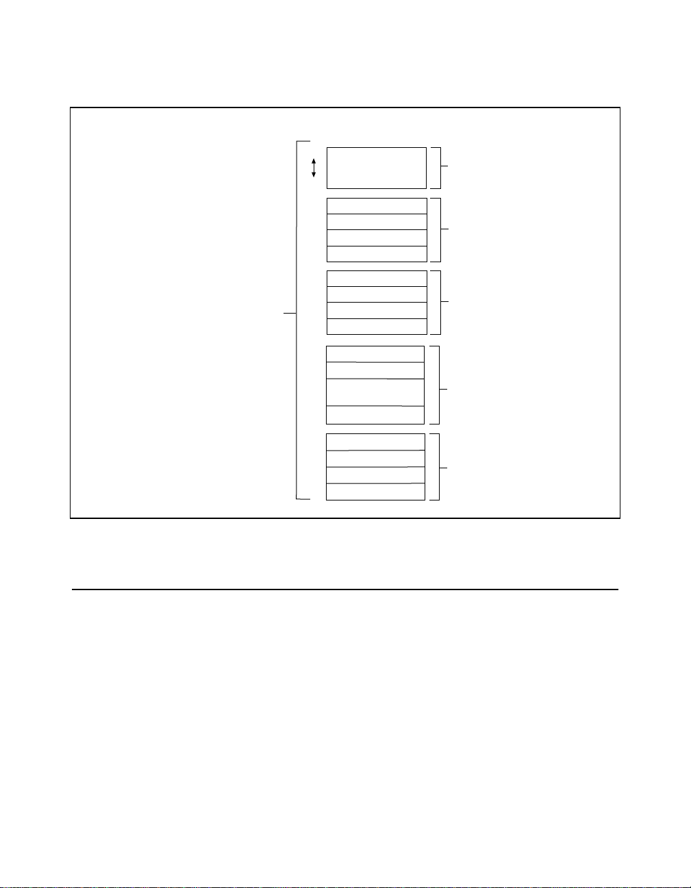
Figure 1-1. VXI Configuration Registers ................................................................1-2
Figure 1-2. VXI Software Protocols ........................................................................1-3
Figure 2-1. An Embedded Controller Connected to Other Frames via
Mainframe Extenders Using MXI-2 .....................................................2-6
Figure 2-2. An External Controller Connected Using MXI-2 to a Number of
Remote Controllers ...............................................................................2-7
Figure 3-1. Preemptive Word Serial Mutual Exclusion (Per Logical Address).......3-9
Figure 3-2. NI-VXI Servant Word Serial Model .....................................................3-16
Figure 3-3. NI-VXI Interrupt and Signal Model......................................................3-39
Figure 3-4. NI-VXI Interrupt and Signal Model......................................................3-45
Table A-1. Function Listing by Group....................................................................A-1
Table A-2. Function Listing by Name.....................................................................A-8
© National Instruments Corporation xi NI-VXI User Manual
Page 11

This manual describes in detail the features of the NI-VXI software and
the VXI/VME function calls in the C/C++ and BASIC languages.
Organization of This Manual
The NI-VXI User Manual for C/C++ and BASIC is organized as
follows:
•
Chapter 1, Overview of NI-VXI, introduces you to the concepts of
VXI (VME eXtensions for Instrumentation), VME, MXI
(Multisystem eXtension Interface), and their relationship to the
NI-VXI application programmer’s interface (API).
•
Chapter 2, Introduction to the NI-VXI Functions, introduces you to
the NI-VXI functions and their capabilities. Additional discussion
is provided for each function’s parameters and includes descriptions
of the application development environment. This chapter
concludes with an overview on using the NI-VXI application
programming interface.
•
Chapter 3, Software Overview, describes the C/C++ and BASIC
usage of VXI and VME functions and briefly describes each
function. Functions are listed alphabetically in each functional
group.
•
Appendix A, Function Classification Reference, contains two tables
you can use as a quick reference. Table A-1, Function Listing by
Group, lists the NI-VXI functions by their group association. This
arrangement can help you determine easily which functions are
available within each group. Table A-2, Function Listing by Name,
lists each function alphabetically. You can refer to this table if you
don't remember the group association of a particular function. Both
tables use checkmarks to denote whether a VXI function also
applies to VME and also whether it is associated with C/C++ and/or
BASIC.
About
This
Manual
© National Instruments Corporation xiii NI-VXI User Manual
Page 12

About This Manual
•
Appendix B, Customer Communication, contains forms you can use
to request help from National Instruments or to comment on our
manuals.
•
The Glossary contains an alphabetical list and description of terms
used in this manual, including abbreviations, acronyms, and metric
prefixes.
•
The Index contains an alphabetical list of key terms and topics used
in this manual, including the page where each one can be found.
Conventions Used in This Manual
The following conventions are used in this manual:
bold Bold text denotes parameters, menus, menu items, dialog box buttons
or options, or error messages.
bold italic Bold italic text denotes a note, caution, or warning.
bold
monospace
Bold text in this font denotes the messages and responses that the
computer automatically prints to the screen. This font also emphasizes
lines of example code that are different from the other examples.
italic Italic text denotes emphasis, a cross reference, or an introduction to a
key concept.
monospace
Text in this font denotes the names of all VXI function calls, source
code, sections of code, function syntax, console responses, variable
names, and syntax examples.
In this manual numbers are decimal unless noted as follows:
•
Binary numbers are indicated by a -b suffix (for example,
11010101b).
•
Octal numbers are indicated by an -o suffix (for example, 325o).
•
Hexadecimal numbers are indicated by an -h suffix (for example,
D5h).
•
ASCII character and string values are indicated by double quotation
marks (for example, "This is a string").
•
Long values are indicated by an -L suffix (for example, 0x1111L).
Abbreviations, acronyms, metric prefixes, mnemonics, symbols, and
terms are listed in the Glossary.
NI-VXI User Manual xiv © National Instruments Corporation
Page 13

Related Documentation
The following documents contain information that you may find
helpful as you read this manual:
•
IEEE Standard for a Versatile Backplane Bus: VMEbus,
ANSI/IEEE Standard 1014-1987
•
Multisystem Extension Interface Bus Specification, Version 2.0
•
VXI-1, VXIbus System Specification, Revision 1.4, VXIbus
Consortium
•
VXI-6, VXIbus Mainframe Extender Specification, Revision 1.0,
VXIbus Consortium
Customer Communication
National Instruments wants to receive your comments on our products
and manuals. We are interested in the applications you develop with
our products, and we want to help if you have problems with them. To
make it easy for you to contact us, this manual contains comment and
configuration forms for you to complete. These forms are in
Appendix B, Customer Communication, at the end of this manual.
About This Manual
© National Instruments Corporation xv NI-VXI User Manual
Page 14
Overview of NI-VXI
This chapter introduces you to the concepts of VXI (VME eXtensions
for Instrumentation), VME, MXI (Multisystem eXtension Interface),
and their relationship to the NI-VXI application programmer’s
interface (API).
Comprehensive functions for programming the VXIbus/VMEbus are
included with the NI-VXI software. They are available for a variety of
controller platforms and operating systems. Among the compatible
platforms are the National Instruments line of embedded controllers
and external computers that have a MXIbus interface.
Chapter
1
Note:
The following chapter discusses features unique to VXI as well as
common VXI/VME features. VME users can skip to the section entitled
Interrupts and Asynchronous Events.
VXIbus Overview
Concepts of the VXIbus specification include the VXI device,
message-based devices, the World Serial Protocol, the
Commander/Servant hierarchy, and hardware interrupts and
asynchronous events.
VXI Devices
A VXI device has a unique logical address, which serves as a means of
referencing the device in the VXI system. This logical address is
analogous to a GPIB device address. VXI uses an 8-bit logical address,
allowing for up to 256 VXI devices in a VXI system.
Each VXI device must have a specific set of registers, called
configuration registers (Figure 1-1) .These registers are located in the
upper 16 KB of the 64 KB A16 VME address space. The logical
address of a VXI device determines the location of the device’s
configuration registers in the 16 KB area reserved by VXI.
© National Instruments Corporation 1-1 NI-VXI User Manual
Page 15
Chapter 1 Overview of NI-VXI
VXI Configuration
Space
• Upper 16 KB of A16
space reserved for
VXI configuration space
• 64 bytes per device
• 8-bit logical
address specifies
base address for
each device
• 256 devices per
VXI system
Offset
3F
20
Reserved
IE
Reserved
1C
Reserved
1A
Reserved
18
A32 Pointer Low
16
A32 Pointer High
14
A24 Pointer Low
12
A32 Pointer High
10
0E
Data Low
Data High
0C
Response/Data
0A
Extended
Protocol/Signal
08
Offset
06
Status/Control
04
Device Type
02
ID Register
00
Device
Dependent
Registers
Reserved
by VXIbus
Specification
Shared Memory
Protocol
Registers
Communication
Registers
Required for VXI
Message-Based
Devices
Configuration
Registers
Required for all
VXI Devices
Figure 1-1. VXI Configuration Registers
Register-Based Devices
Through the use of the VXI configuration registers, which are required
for all VXI devices, the system can identify each VXI device, its type,
model and manufacturer, address space, and memory requirements.
VXIbus devices with only this minimum level of capability are called
register-based devices. With this common set of configuration
registers, the centralized Resource Manager (RM), a software module,
can perform automatic system configuration when the system is
initialized.
NI-VXI User Manual 1-2 © National Instruments Corporation
Page 16

Message-Based Devices
In addition to register-based devices, the VXIbus specification also
defines message-based devices, which are required to have
communication registers in addition to configuration registers. All
message-based VXIbus devices, regardless of the manufacturer, can
communicate at a minimum level using the VXI-specified Word Serial
Protocol. In addition, you can establish higher-performance
communication channels, such as shared-memory channels, to take
advantage of the VXIbus bandwidth capabilities.
Device-
Specific
Protocols
Device-
Specific
Protocols
Shared-
Memory
Protocol
Chapter 1 Overview of NI-VXI
Device-
Specific
Protocols
488.2
Syntax
488-VXIbus
Protocol
Word Serial Protocol
Device-
Specific
Protocols
Configuration Registers
Communication Registers
Figure 1-2. VXI Software Protocols
Word Serial Protocol
The VXIbus Word Serial Protocol is a standardized message-passing
protocol. This protocol is functionally very similar to the IEEE 488
protocol, which transfers data messages to and from devices one byte
(or word) at a time. Thus, VXI message-based devices communicate in
© National Instruments Corporation 1-3 NI-VXI User Manual
Page 17

Chapter 1 Overview of NI-VXI
a fashion very similar to IEEE 488 instruments. In general,
message-based devices typically contain some level of local
intelligence that uses or requires a high level of communication. In
addition, the Word Serial Protocol has messages for configuring
message-based devices and system resources.
All VXI message-based devices are required to use the Word Serial
Protocol and communicate in a standard way. The protocol is called
word serial, because if you want to communicate with a message-based
device, you do so by writing and reading 16-bit words one at a time to
and from the Data In (write Data Low) and Data Out (read Data Low)
hardware registers located on the device itself. Word serial
communication is paced by bits in the device’s response register that
indicate whether the Data In register is empty and whether the Data
Out register is full. This operation is very similar to the operation of a
Universal Asynchronous Receiver Transmitter (UART) on a serial port.
Commander/Servant Hierarchies
The VXIbus specification defines a Commander/Servant
communication protocol you can use to construct hierarchical systems
using conceptual layers of VXI devices. The resulting structure is like a
tree. A Commander is any device in the hierarchy with one or more
associated lower-level devices, or Servants. A Servant is any device in
the subtree of a Commander. A device can be both a Commander and a
Servant in a multiple-level hierarchy.
A Commander has exclusive control of its immediate Servants’ (one or
more) communication and configuration registers. Any VXI module
has one and only one Commander. Commanders use the Word Serial
Protocol to communicate with Servants through the Servants’
communication registers. Servants communicate with their
Commander, responding to the Word Serial commands and queries
from their Commander. Servants can also communicate asynchronous
status and events to their Commander through hardware interrupts, or
by writing specific messages directly to their Commander’s Signal
register.
Interrupts and Asynchronous Events
Servants can communicate asynchronous status and events to their
Commander through hardware interrupts or by writing specific
messages (signals) directly to their Commander’s hardware Signal
NI-VXI User Manual 1-4 © National Instruments Corporation
Page 18

register. Devices that do not have bus master capability always transmit
such information via interrupts, whereas devices that do have bus
master capability can either use interrupts or send signals. Some
devices can receive only signals, some only interrupts, while some
others can receive both signals and interrupts.
The VXIbus specification defines Word Serial commands so that a
Commander can understand the capabilities of its Servants and
configure them to generate interrupts or signals in a particular way. For
example, a Commander can instruct its Servants to use a particular
interrupt line, to send signals rather than generate interrupts, or
configure the reporting of only certain status or error conditions.
Although the Word Serial Protocol is reserved for Commander/Servant
communications, you can establish peer-to-peer communication
between two VXI/VME devices through a specified shared-memory
protocol or simply by writing specific messages directly to the device’s
Signal register, in addition to the VXI/VME interrupt lines.
MXIbus Overview
The MXIbus is a high-performance communication link that
interconnects devices with a cabled communication link for very
high-speed communication between physically separate devices. The
emergence of the VXIbus inspired MXI. National Instruments, a
member of the VXIbus Consortium and the VITA organization,
recognized that VXI requires a new generation of connectivity for the
instrumentation systems. Additionally, National Instruments realized
that the same technology could be used also for the VMEbus, which is
the foundation technology under VXI. National Instruments developed
the MXIbus specification over a period of two years and announced it
in April 1989 as an open industry standard.
Chapter 1 Overview of NI-VXI
MXI-2 Overview
MXI-2 is the second generation of the National Instruments MXIbus
product line. The MXIbus is a general-purpose, 32-bit, multimaster
system bus on a cable. MXI-2 expands the number of signals on a
standard MXI cable by including VXI triggers, all VXI/VME
interrupts, CLK10, and all of the utility bus signals (SYSFAIL*,
SYSRESET*, and ACFAIL*).
© National Instruments Corporation 1-5 NI-VXI User Manual
Page 19

Chapter 1 Overview of NI-VXI
Because MXI-2 incorporates all of these new signals into a single
connector, the triggers, interrupts, and utility signals can be extended
not only to other mainframes but also to the local CPU in all MXI-2
products using a single cable. Thus, MXI-2 lets CPU interface boards
such as the PCI-MXI-2 perform as though they were plugged directly
into the VXI/VME backplane.
In addition, MXI-2 boosts data throughput performance past
previous-generation MXIbus products by defining new
high-performance protocols. MXI-2 is a superset of MXI. However,
MXI-2 defines synchronous MXI block data transfers which surpass
previous block data throughput benchmarks. The new synchronous
MXI block protocol increases MXI-2 throughput to a maximum of
33 MB/s between two MXI-2 devices. All National Instruments MXI-2
boards are capable of initiating and responding to synchronous MXI
block cycles.
NI-VXI User Manual 1-6 © National Instruments Corporation
Page 20

Chapter
Introduction to the
NI-VXI Functions
This chapter introduces you to the NI-VXI functions and their
capabilities. Additional discussion is provided for each function’s
parameters and includes descriptions of the application development
environment. This chapter concludes with an overview on using the
NI-VXI application programming interface.
The NI-VXI functions are a set of C/C++ and BASIC language
functions you can use to perform operations with a VXI/VME system.
The NI-VXI C/C++ language interface is consistent across hardware
platforms and operating systems.
Function Groups
The NI-VXI functions are divided into several groups. All of them
apply to VXI, but some groups are not applicable to VME.
VXI/VME Function Groups
The following NI-VXI function groups apply to both VXI and VME.
•
System Configuration Functions—The system configuration
functions provide functionality to initialize the NI-VXI software. In
addition, the system configuration functions can retrieve or modify
information about devices in your VXI/VME system.
•
High-Level VXIbus Access Functions—Similar to the low-level
VXI/VMEbus access functions, the high-level VXI/VMEbus access
functions give you direct access to the VXI/VMEbus address
spaces. You can use these functions to read, write, and move blocks
of data between any of the VXI/VMEbus address spaces. You can
specify the main VXI/VMEbus privilege mode or byte order. The
functions trap and report bus errors. When the execution speed is
not a critical issue, the high-level VXI/VMEbus access functions
provide an easy-to-use interface.
2
© National Instruments Corporation 2-1 NI-VXI User Manual
Page 21

Chapter 2 Introduction to the NI-VXI Functions
•
Low-Level VXIbus Access Functions—Low-level VXI/VMEbus
access functions are the fastest access method for directly reading
from or writing to any of the VXI/VMEbus address spaces. You
can use these functions to obtain a pointer that is directly mapped to
a particular VXI/VMEbus address. Then you use the pointer with
the low-level VXI/VMEbus access functions to read from or write
to the VXI/VMEbus address space. When using these functions in
your application, you need to consider certain programming
constraints and error conditions such as bus errors (BERR*).
•
Local Resource Access Functions—Local resource access functions
let you access miscellaneous local resources such as the local CPU
VXI register set, Slot 0 MODID operations (when the local device
is configured for Slot 0 operation), and the local CPU VXI Shared
RAM. These functions are useful for shared memory type
communication, for the non-Resource Manager operation (when the
local CPU is not the Resource Manager), and for debugging
purposes.
•
VXI Signal Functions—VXI signals are a method for VXI bus
masters to interrupt another device. You can route VXI signals to a
handler or queue them on a global signal queue. You can use these
functions to specify the signal routing, install handlers, manipulate
the global signal queue, and wait for a particular signal value (or set
of values) to be received.
Note:
Although signals are defined in the VXI specification, VME customers
may still use the signal register available on any VXI/VME/MXI
hardware. This register provides a simple notification mechanism that can
be used by any bus-master.
•
VXI/VME Interrupt Functions—By default, interrupts are processed
as VXI signals (either with a handler or by queuing on the global
signal queue). The VXI/VME interrupt functions can specify the
processing method and install interrupt service routines. In addition,
the VXI/VME interrupt functions can assert specified VXI/VME
interrupt lines with a specified status/ID value.
•
System Interrupt Handler Functions—The system interrupt handler
functions let you install handlers for the various system interrupt
conditions. These conditions include Sysfail, ACfail, bus error, and
soft reset interrupts.
•
VXI/VMEbus Extender Functions—The VXI/VMEbus extender
functions can dynamically configure multiple-mainframe mappings
NI-VXI User Manual 2-2 © National Instruments Corporation
Page 22

of the VXI/VME interrupt lines, VXI TTL triggers, VXI ECL
triggers, and utility bus signals. The National Instruments Resource
Manager configures the mainframe extenders with settings based on
user-modifiable configuration files.
VXI-Only Function Groups
The following NI-VXI function groups do not apply to VME.
•
Commander Word Serial Protocol Functions—Word Serial is a
form of communication between VXI message-based devices. The
Commander Word Serial functions give you the necessary
capabilities to communicate with a message-based Servant device
using the Word Serial, Longword Serial, or Extended Longword
Serial protocols. These capabilities include the sending of
commands and queries and the reading and writing of buffers.
•
Servant Word Serial Protocol Functions—Servant Word Serial
functions allow you to communicate with the message-based
Commander of the local CPU (the device on which the NI-VXI
interface resides) using the Word Serial, Longword Serial, or
Extended Longword Serial protocols. These capabilities include
command/query handling and buffer reads/writes.
•
VXI Trigger Functions—The VXI trigger functions let you source
and accept any of the VXIbus trigger protocols. The actual
capabilities available depend on the specific hardware platform.
The VXI trigger functions can install handlers for various trigger
interrupt conditions.
Chapter 2 Introduction to the NI-VXI Functions
Calling Syntax
The interface is the same regardless of the development environment or
the operating system used. Great care has been taken to accommodate
all types of operating systems with the same functional interface
(C/C++ source-level compatible), whether it is non-multitasking (for
example, MS-DOS), cooperative multitasking (such as Microsoft
Windows 3.x or Macintosh OS), multitasking (for example, UNIX,
Wndows 95, or Windows NT), or real-time (such as LynxOS or
VxWorks). The NI-VXI interface includes most of the mutual
exclusion necessary for a multitasking environment. Each individual
platform has been optimized within the boundaries of the particular
hardware and operating system environment.
© National Instruments Corporation 2
-
3 NI-VXI User Manual
Page 23

Chapter 2 Introduction to the NI-VXI Functions
LabWindows/CVI
You can use the functions described in this manual with
LabWindows/CVI. LabWindows/CVI is an integrated development
environment for building instrumentation applications using the
ANSI C programming language. You can use LabWindows/CVI with
Microsoft Windows on PC-compatible computers or with Solaris on
Sun SPARCstations. The source code you develop is portable across
either platform.
National Instruments offers VXI/VME development systems for these
two platforms that link the NI-VXI driver software into
LabWindows/CVI to control VXI instruments from either embedded
VXI/VME controllers or external computers equipped with a MXI
interface. All of the NI-VXI functions described in this manual are
completely compatible with LabWindows/CVI.
Type Definitions
The following data types are used for all parameters in the NI-VXI
functions and in the actual NI-VXI library function definitions. NI-VXI
uses this list of parameter types as an independent method for
specifying data type sizes among the various operating systems and
target CPUs of the NI-VXI software interface.
C/C++ Example:
typedef char INT8; /* 8-bit signed integer */
typedef unsigned char UINT8; /* 8-bit unsigned integer */
typedef short INT16; /* 16-bit signed integer */
typedef unsigned short UINT16; /* 16-bit unsigned integer */
typedef long INT32; /* 32-bit signed integer */
typedef unsigned long UINT32; /* 32-bit unsigned integer */
Input Versus Output Parameters
Because all C/C++ function calls pass function parameters by value
(not by reference), you must specify the address of the parameter when
&
the parameter is an output parameter. The C/C++ “
accomplishes this task.
For example:
ret = VXIinReg (la, reg, &value);
NI-VXI User Manual 2-4 © National Instruments Corporation
” operator
Page 24

Chapter 2 Introduction to the NI-VXI Functions
Because
the function instead of
value
is an output parameter,
value
Return Values and System Errors
All NI-VXI functions return a status indicating success or failure. The
return code of 0x8000 is reserved as a return status value for any
function to signify that a system error occurred during the function call
except for the commander word serial operations. This error is specific
to the operating system on which the NI-VXI interface is running.
Multiple Mainframe Support
The NI-VXI functions described in this manual support multiple
mainframes both in external CPU configurations and embedded CPU
configurations. The Startup Resource Manager supports one or more
mainframe extenders and configures a single- or multiple-mainframe
VXI/VME system. Refer to the VXIbus Mainframe Extender
Specification, Revision 1.3 or later, for more details on multiple
mainframe systems.
If you have a multiple-mainframe VXI/VME system, please continue
with the following sections. If you have a single-mainframe system,
you can skip to the Using NI-VXI section later in this chapter.
&value
. The input parameters are la and
is used when calling
reg
.
Controllers
A controller is a device that is capable of controlling other devices. A
desktop computer with a MXI interface board, an embedded computer
in a VXI/VME chassis, a VXI-MXI, and a VME-MXI may all be
controllers depending on the configuration of the system.
There are several types of controllers that may exist in a VXI/VME
system; embedded, external, and remote.
•
Embedded controller—A computer plugged directly into the
VXI/VME backplane. An example is the National Instruments
VXIpc-850. All of the required VXI/VME interface capabilities are
built directly onto the computer itself. An embedded computer has
direct access to the VXI/VMEbus backplane in which it is installed.
•
Remote controller—A device in the VXI/VME system that has the
capability to control the VXI/VMEbus, but has no intelligent CPU
installed. An example is the VXI-MXI-2. In NI-VXI, the
parent-side VXI-MXI-2 (that is, the VXI-MXI-2 with a MXI-2
© National Instruments Corporation 2
-
5 NI-VXI User Manual
Page 25
Chapter 2 Introduction to the NI-VXI Functions
cable connected towards the root frame) in the frame acts as a
remote controller. An embedded or external controller may use a
remote controller to control the remote mainframe.
•
External controller—A desktop computer or workstation connected
to the VXI/VME system via a MXI interface board. An example is
a standard personal computer with a PCI-MXI-2 installed.
In general, a multiple mainframe VXI/VME system will have one of
the following controller configurations:
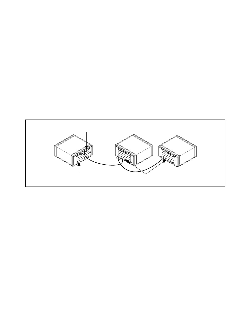
•
An embedded controller in one frame that is connected to other
frames via mainframe extenders using MXI-2. VXI-MXI-2 or
VME-MXI-2 boards in the other frames can also be used as remote
controllers. See Figure 2-1.
Extender Only
®
NATIONAL
INSTRUMENTS
bus
NATIONAL
INSTRUMENTS
®
bus
NATIONAL
INSTRUMENTS
®
bus
Embedded Controller
Extender and Remote Controller
Figure 2-1. An Embedded Controller Connected to Other Frames via
Mainframe Extenders Using MXI-2
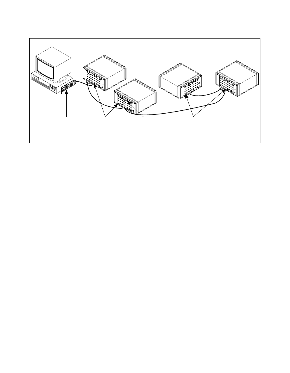
•
An external controller connected using MXI-2 to a number of
remote controllers, each in a separate frame. The external controller
can use the remote controllers for control of the VXI/VME system,
or it can use its own controller capabilities. See Figure 2-2.
NI-VXI User Manual 2-6 © National Instruments Corporation
Page 26
Chapter 2 Introduction to the NI-VXI Functions
®
NATIONAL
NATIONAL
INSTRUMENTS
®
bus
NATIONAL
INSTRUMENTS
®
bus
INSTRUMENTS
bus
NATIONAL
INSTRUMENTS
®
bus
External
Controller
Remote Controller
and Extender
Extender
Only
Figure 2-2. An External Controller Connected Using MXI-2 to a
Number of Remote Controllers
The extender and controller Parameters
In NI-VXI, some functions require a parameter named extender or
controller. Since some extenders act as controllers, there is often
confusion concerning what logical addresses should be passed to these
functions.
The extender parameter is the logical address of a mainframe extender
on which the function should be performed. Usually, functions with an
extender parameter involve the mapping of interrupt lines or trigger
lines into or out of a frame.
The controller parameter is the logical address of an embedded,
external, extending, or remote controller. Usually, functions with a
controller parameter involve sourcing or sensing particular interrupts
or triggers in a frame. According to the definitions of the different
types of controllers, the only valid logical addresses for the controller
parameter are:
•
The external or embedded controller on which the program is
running
•
A parent-side VXI-MXI-2 or VME-MXI-2 in a frame
Remote Controller
and Extender
© National Instruments Corporation 2
-
7 NI-VXI User Manual
Page 27

Chapter 2 Introduction to the NI-VXI Functions
Most functions that take a controller parameter will allow you to pass
(-1) as the logical address. This selects the default controller for the
system. Notice that the default controller is determined by the
following factors:
•
If the program is running on an embedded controller, the default
controller is the embedded controller.
•
If the program is running on an external controller, you will be
able to configure whether the default controller is the external
controller or the remote controller with the lowest numbered
logical address. With this behavior, if you write a program on an
embedded controller referring to the controller as logical
address-1, you will be able to swap the embedded controller
configuration with an external controller configuration without
changing your source code.
Notice that -1 is never a valid value for the extender parameter. In
addition, the logical addresses of embedded and external controllers
also are never valid values for the extender parameter. The extender
parameter refers only to devices that can map interrupt lines, trigger
lines, or other signals into or out of a frame.
NI-VXI User Manual 2-8 © National Instruments Corporation
Page 28

Using NI-VXI
Header Files
Chapter 2 Introduction to the NI-VXI Functions
This section presents a general overview of the more commonly used
class of functions available in NI-VXI. Additional information
summarizes how you can use the functions to perform certain tasks and
further describes the general structure of NI-VXI programming.
Although
nivxi.h
is the only header file you need to include in your
program for NI-VXI, the software distribution actually includes several
additional header files along with
nivxi.h
. Some of these files have
type definitions and macros that can make using NI-VXI easier, and
make the code more portable across different platforms. The three main
files of interest are
datasize.h, busacc.h
, and
devinfo.h
.
The datasize.h File
datasize.h
The
program. For example, INT16 is defined as a 16-bit signed integer, and
UINT32 is defined as a 32-bit unsigned integer. Using these types
benefits you by letting you apply specific type sizes across platforms.
Using undefined types can cause problems when porting your
application between platforms. For example, an int in DOS is a 16-bit
number but a 32-bit number in Solaris or LabWindows/CVI.
file defines the integer types for use in your
In addition to the integers,
uses such as interrupt handlers. For example,
interrupt handler type. Merely defining a variable with this type is
sufficient to create the function prototype necessary for your interrupt
handler. Also, different platforms require different flags for use with
interrupt handlers. To simplify this problem,
NIVXI_HQUAL
NIVXI_HSPEC
and
definition and take care of the platform dependencies. See the
Interrupts and Signals section later in this chapter and your
file for more information. In addition, refer to Chapter 3, Software
Overview for specific information.
© National Instruments Corporation 2
datasize.h
defines several types for other
NIVXI_HVXIINT
datasize.h
is an
defines
, which are used in the handler
read me
-
9 NI-VXI User Manual
Page 29

Chapter 2 Introduction to the NI-VXI Functions
The busacc.h File
busacc.h
The
high/low-level and slave memory access functions (see the Master
Memory Access and Slave Memory Access sections later in this
chapter). To make the code more readable,
elements as memory space, privilege mode, and byte order as
constants, and it defines macros to combine these constants into the
necessary access parameters. Examine the header file for more
information on the available macros and constants. You can see these
tools in use by reviewing the example programs on memory accesses
that appear later in this chapter and also the example programs
included with your software.
The devinfo.h File
devinfo.h
The
GetDevInfo()
Functions section in Chapter 3, Software Overview. The purpose of this
function is to return various information about the system.
GetDevInfo()
one large data structure. The header file
UserLAEntry
Refer to the header file for the exact definition of the data structure.
file defines constants and macros for use with the
busacc.h
defines such
file contains a data type that is used with the
function described in the System Configuration
can return the information either a piece at a time, or in
devinfo.h
contains the type
, which defines the data structure that the function uses.
The Beginning and End of an NI-VXI Program
All NI-VXI programs must call
driver before using any other functions. You must call
CloseVXIlibrary()
before exiting from your program to free
resources associated with NI-VXI. The first function creates the
internal structure needed to make the NI-VXI interface operational.
InitVXIlibrary()
When
other functions can access information obtained by
VXIbus Resource Manager, as well as use other NI-VXI features such
as interrupt handlers and windows for memory access. The second
function destroys this structure and frees the associated memory. All
programs using NI-VXI must call
other NI-VXI function. In addition, your program should include a call
CloseVXIlibrary()
to
NI-VXI User Manual 2-10 © National Instruments Corporation
InitVXIlibrary()
to initialize the
completes its initialization procedures,
RESMAN
InitVXIlibrary()
before any
before exiting.
, the
Page 30

Chapter 2 Introduction to the NI-VXI Functions
An important note about these two functions is that the internal
structure maintains a record of the number of calls to
InitVXIlibrary()
InitVXIlibrary()
CloseVXIlibrary().
and
Although
needs to be called only once, the structure of
your program may cause the function to be called multiple times. A
successful call to
InitVXIlibrary()
returns either a zero or a one. A
zero indicates that the structure has been created, and a one indicates
that the structure was created by an earlier call so no action was taken
(other than incrementing the count of the number of
InitVXIlibrary()
calls).
CloseVXIlibrary()
When
either a zero or a one. A zero indicates that the structure has been
successfully destroyed, and a one indicates that there are still
outstanding calls to
the structure is destroyed. The outcome of all of this is that when
exiting a program, you should call
number of times that you have called
Caution:
In environments where all applications share NI-VXI, and hence the
internal structure (such as Microsoft Windows), it can be dangerous for
any one application to call
because this can close out the structure from under another application. It
is vital to keep track of the number of times you have called
InitVXIlibrary()
System Configuration Tools
The System Configuration Functions section of Chapter 3, Software
Overview, describes functions that a program can use to access
information about the system. This is obtained either through
configuration information or from information obtained by
Armed with these functions, a program can be more flexible to changes
within the system.
returns a successful code, it also returns
InitVXIlibrary()
CloseVXIlibrary()
.
that must be closed before
CloseVXIlibrary
InitVXIlibrary()
until it returns zero
() the same
.
RESMAN
.
Note:
The examples in this manual do not check for either warnings or errors in
most of the functions’ return codes. This step is omitted only to simplify
the example programs. We strongly recommend that you include error
checking in your own programs.
© National Instruments Corporation 2
-
11 NI-VXI User Manual
Page 31

Chapter 2 Introduction to the NI-VXI Functions
For example, all VXI devices have at least one logical address by
which they can be accessed. However, it is simple to change the logical
address of most devices. Therefore, any program that uses a constant as
a logical address of a particular device can fail if that device is
reassigned to a different logical address. Programmers can use the
NI-VXI function
device—such as the manufacturer ID and model code—and receive the
device’s current logical address.
Consider the case of wanting to locate a device with manufacturer’s
code ABCh and model number 123h. You could use the following code
to determine the logical address.
FindDevLA()
to input information about the
C/C++ Example
main() {
INT16 ret, la;
ret = InitVXIlibrary();
/* -1 and empty quotes are used for don't cares */
ret = FindDevLA("", 0xABC, 0x123, -1, -1, -1, -1, &la);
if (ret < 0)
else
ret = CloseVXIlibrary();
}
:
printf("No such device found.\n");
printf("The logical address is %d\n", la);
In a similar fashion, the function
assortment of information on a device, such as the manufacturer name
and number, the base and size of A24/32 memory, and the protocols
that the device supports. This information can be returned in either a
piecemeal fashion or in one large data structure. Notice that this data
structure is a user-defined type,
devinfo.h
header file.
♦ For VME devices, this information cannot be determined by the
VXIbus Resource manager. However, you can enter this information
into the Non-VXI Device Editor in
allow you to use these functions to retrieve information about the
devices at run-time.
GetDevInfo()
UserLAEntry
VXIedit
or
can return a wide
, which is defined in the
VXItedit
. This will
NI-VXI User Manual 2-12 © National Instruments Corporation
Page 32

Word Serial Communication
When communicating with a message-based devices (MBD) in VXI,
the protocol for string passing is known as Word Serial. The term is
derived from the fact that all commands are 16 bits in length (word
length), and that strings are sent serially, or one byte at a time. VXI
also accommodates Long Word Serial (32-bit commands), and
Extended Long Word Serial (48-bit commands). However, the VXIbus
specification revision 1.4 states that only Word Serial commands have
been defined.
Word Serial Protocol is based on a Commander writing 16-bit
commands to a Servant register (See the Commander Word Serial
Protocol Functions in Chapter 3, Software Overview, for more
information on the protocol). The VXIbus specification has defined
several commands, such as Byte Available, Byte Request, and Clear.
The bit patterns for Word Serial commands have been laid out in the
VXIbus specification, and your application can send these commands
to a Servant via the
communication is the most common use for Word Serial Protocol, the
functions
Available (for sending a byte to a servant) and Byte Request (for
retrieving a byte from a Servant) repetitively to send or receive strings
as defined by the Word Serial Protocol. In addition, other common
commands such as Clear have been encapsulated in their own
functions, such as
WSwrt()
WScmd()
WSrd()
and
WSclr()
Chapter 2 Introduction to the NI-VXI Functions
function. However, because string
use the Word Serial commands Byte
.
,
Chapter 3
Software Overview
pertaining to message-based communication for the Commander.
However, there are times when you want the controller to operate as a
Word Serial Servant. NI-VXI allows for the controller to accept Word
Serial commands from a Commander. This chapter also
different set of functions that a Servant uses for message-based
communication with its Commander.
For example,
WSSrd()
controller to accept the Byte Request commands from a controller and
respond with the string specified in the function. In a similar fashion,
WSSwrt()
the
function programs the controller to accept Byte
Available commands. National Instruments strongly recommends that
if you want to program the controller as a Servant, you should aim to
become familiar with the Word Serial Protocol in detail, and implement
as much of the protocol as possible to simplify the debugging and
operation of the program.
© National Instruments Corporation 2
describes all NI-VXI functions
scribes a
de
(Word Serial Servant Read) sets up the
-
13 NI-VXI User Manual
Page 33

Chapter 2 Introduction to the NI-VXI Functions
Master Memory Access
You can access VXIbus memory directly through the NI-VXI
high-level and low-level VXIbus access functions, within the
capabilities of the controller. The main difference between the
high-level and low-level access functions is in the amount of
encapsulation given by NI-VXI.
The high-level VXIbus access functions include functions such as
VXIin()
VXI system without dealing with such details as memory-mapping
windows, status checking, and recovering from bus timeouts. Although
these functions tend to have more overhead associated with them than
the low-level functions, they are much simpler to use and typically
require less debugging. We recommend that beginner programmers in
VXI rely on the high-level functions until they are familiar with VXI
memory accesses.
You can use the low-level VXI/VMEbus access functions if you want
to access VXI/VME memory with as little overhead as possible.
Although you now have to perform such actions as bus error handling
and mapping—which are handled automatically by the high-level
functions—you can experience a performance gain if you optimize for
the particular accesses you are performing. Consider the following
sample code, which performs a memory access using the low-level
functions. Notice that there is no bus error handler installed by the
program (See the Interrupts and Signals section). Instead, the program
uses the NI-VXI default bus error handler. This handler automatically
increments the
and
VXImove()
BusErrorRecv
that you can use to access memory in the
global variable.
C/C++ Example:
#include <nivxi.h> /* BusErrorRecv defined in nivxi.h */
#include <stdio.h>
main() {
NI-VXI User Manual 2-14 © National Instruments Corporation
INT16 ret, la;
UINT16 *addrptr, svalue;
UINT32 addr, window1;
INT32 timeout;
UINT32 addrptr1;
/* Start all programs with this function */
ret = InitVXIlibrary();
BusErrorRecv = 0; /* Reset global variable */
/* The following code maps the A16 space with the Access Only */
/* access in order to access the A16 space directly. */
addr = 0xc000L; /* Map upper 16 KB of the A16 space */
Page 34

Chapter 2 Introduction to the NI-VXI Functions
timeout = 2000L; /* 2 seconds */
/* Notice the use of the macros for defining the access */
/* parameters. These can be found in the NI-VXI header files */
addrptr1 = (UINT32) MapVXIAddress(AccessP_Space(A16_SPACE) |
if (ret >= 0) /** MapVXIAddress call is successful **/
{
/* The following code reads the ID register of a device */
/* at logical address 10. */
la = 10;
addrptr = (UINT16 *)((UINT32) addrptr1 + 64 * la);
VXIpeek(addrptr,2, &svalue));
AccessP_Priv(NonPriv_DATA) |
AccessP_BO(MOTOROLA_ORDER) |
AccessP_Owner(0),
addr, timeout, &window1, &ret);
if (BusErrorRecv)
else
ret = UnMapVXIAddress(window1);
} else
printf("Unable to access window.\n");
/* Close library when done */
ret = CloseVXIlibrary();
}
printf("Bus Error has occurred.\n");
printf("Value read was %hd.\n", svalue));
Notice that the return variable for the
MapVXIAddress()
function is a
pointer. While you can dereference this pointer directly on some
platforms, we recommend that you use the
VXIpoke()
You can define
to force NI-VXI to use a version of
macros and functions in NI-VXI instead.
BINARY_COMPATIBLE
when compiling your program
VXIpeek()
VXIpeek()
and
and
VXIpoke()
macros that will work on all embedded and MXI platforms. In addition,
you can use the functions, rather than the macros, to ensure future
compatibility. To force the compiler to use the functions, put the
function name in parentheses, for example,
(VXIpoke) (addrptr, 2, 0);
instead of
VXIpoke (addrptr, 2, 0);
© National Instruments Corporation 2
-
15 NI-VXI User Manual
Page 35

Chapter 2 Introduction to the NI-VXI Functions
Note:
On modern, 32-bit operating systems running on high-performance
processors (such as Microsoft Windows NT on a Pentium or Solaris 2
on a SPARC), we have found no performance gained by using macros
instead of functions. For this reason, we strongly recommend that you use
functions on these platforms to allow your program to be more portable
across future platforms.
Slave Memory Access
It is possible to share local resources such as RAM with the
VXI/VMEbus. You can accomplish this functionality by setting the
appropriate fields in the
editor utility to instruct the controller to respond to bus accesses as a
slave. What address space is used is dependent on the settings in
VXIedit
addresses are assigned by
through the
Keep in mind that when the controller shares its resources, it may not
allocate them from the local system first. For example, if you instruct
the system to share 1 MB of RAM, the controller will map VXI/VME
addresses (as defined by
the controller may not have prevented the local system from also using
this space. For example, on a IBM compatible PC, the first 1 MB of
address space contains not only user RAM, but also the interrupt vector
table, video memory, BIOS, and so on. Therefore, it is important that
you first use
memory, and then communicate this address to the remote master that
will be accessing the slave memory. For example, assume that the
following code will run on a controller that has shared 1 MB of local
RAM.
VXItedit
or
GetDevInfo()
VXImemAlloc()
VXIedit
VXItedit
or
NI-VXI resource
. However, the actual VXI/VMEbus memory
RESMAN
and should be read by the program
function.
RESMAN
) to 1 MB of local memory. However,
to reserve a portion of the shared
C/C++ Example:
main() {
INT16 ret;
UINT32 *useraddr, vxiaddr;
void *bufaddr;
/* Initialize and allocate 4 KB of memory */
ret = InitVXIlibrary();
ret = VXImemAlloc(4096, &useraddr, &vxiaddr);
/* Put code here to communicate vxiaddr */
/* returned by VXImemAlloc */
NI-VXI User Manual 2-16 © National Instruments Corporation
Page 36

Chapter 2 Introduction to the NI-VXI Functions
/* At this point, the remote master can perform */
/* I/O on the shared, allocated space. In addition, */
/* the program can use the local address to perform */
/* I/O on the same space, such as reading back a block */
/* of data */
bufaddr = malloc (4096);
ret = VXImemCopy (useraddr, bufaddr, 4096, 0);
/* Return memory to local system */
ret = VXImemFree(useraddr);
ret = CloseVXIlibrary();
}
Interrupts and Signals
In NI-VXI, you can set up your controller to function as both an
interrupt handler and an interrupter. You can also have your controller
respond to writes to its signal register. Signaling another device
requires the high-level or low-level VXI/VMEbus access functions, as
discussed earlier. In addition, NI-VXI lets you configure both
interrupts and signals to be handled either through callback handlers or
through the signal queue. See the VXI Signal Functions section in
Chapter 3, Software Overview, for more details about the signal queue,
but for now you can look upon it as a FIFO (first-in, first-out) queue
that you can access via the signal queue management functions, such as
SignalDeq()
provide the status/ID obtained from the interrupt acknowledge or from
the signal register. You can use this value to determine which device
generated the interrupt/signal as well as the cause of the event. See the
VXI Interrupt Functions section in Chapter 3, Software Overview, for
more information.
. Both the signal queue and the callback handler will
Handling either signals or interrupts through the signal queue is very
straightforward. You can use the
RouteSignal()
functions to specify that the events should be handled
by the signal queue. After you have enabled the event handler through
either the
EnableSignalInt()
call, the event is placed on the queue when it occurs. You can use the
SignalDeq()
WaitForSignal()
or
from the queue.
Note:
RESMAN
allocates interrupt lines to VXI devices that support the
programmable interrupt command. Devices should use only those
interrupt lines allocated to them. Again, you can use
determine what interrupt lines have been allocated to the controller.
© National Instruments Corporation 2
RouteVXIint()
EnableVXItoSignalInt()
or the
and
functions to retrieve the event
GetDevInfo()
-
17 NI-VXI User Manual
to
Page 37

Chapter 2 Introduction to the NI-VXI Functions
Alternatively, you can choose to handle either signals or interrupts with
a callback handler. You can use
RouteSignal()
to specify that the
events should be handled by the callback handlers rather than the signal
queue. After you have enabled the callback handler through either the
EnableSignalInt()
EnableVXIint()
or the
call, the callback
function will be invoked when the event occurs. Installing and using
callback handlers is very simple with NI-VXI because all of the
operating system interaction is handled for you. The following section
of code gives an example of using an callback handler.
C/C++ Example:
#define VXI_INT_LEVEL 1 /* this sample only interested in level 1 */
/* NIVXI_HVXIINT is a type defined for VXI/VME interrupt callback handlers */
NIVXI_HVXIINT *OldVXIintHandler; /* pointer to save the old handler */
NIVXI_HVXIINT UserVXIintHandler; /* function declr for new handler */
main () {
INT16 ret, controller;
/* Always begin by initializing the NI-VXI library */
ret = InitVXIlibrary ();
controller = -1;
/* Get address of the old handler */
OldVXIintHandler = GetVXIintHandler (VXI_INT_LEVEL);
/* Set callback handler to new user-defined procedure */
ret = DisableVXIint (controller, 1<<(VXI_INT_LEVEL-1));
ret = SetVXIintHandler (1<<(VXI_INT_LEVEL-1), UserVXIintHandler);
ret = EnableVXIint (controller, 1<<(VXI_INT_LEVEL-1));
/**/
/* user code */
/**/
/* Restore callback handler to what it was before we changed it */
ret = DisableVXIint (controller, 1<<(VXI_INT_LEVEL-1));
SetVXIintHandler (1<<(VXI_INT_LEVEL-1), OldVXIintHandler);
ret = EnableVXIint (controller, 1<<(VXI_INT_LEVEL-1));
/* Always close the NI-VXI library before exiting */
CloseVXIlibrary ();
}
/* The NIVXI_HQUAL and NIVXI_HSPEC should bracket */
/* every interrupt handler as shown below. */
NIVXI_HQUAL void NIVXI_HSPEC UserVXIintHandler (INT16 controller,
{
/* user code for processing statusID */
}
NI-VXI User Manual 2-18 © National Instruments Corporation
UINT16 level, UINT32 statusID)
Page 38

Chapter 2 Introduction to the NI-VXI Functions
Note:
Triggers
Although NI-VXI simplifies the installation and use of callback handlers,
it cannot affect how the system handles interrupts. The programmer must
follow programming guidelines set by the chosen operating system. Some
of these guidelines could include using only reentrant functions, adhering
to timing restrictions, and on Macintosh computers, regaining access to
global variables.
The addition of trigger lines to the VMEbus is one improvement the
VXIbus has over VME in the field of instrumentation. To take
advantage of this feature, NI-VXI has a wide selection of functions you
can use to set up your controller to both source and acknowledge
trigger lines. The TIC is a National Instruments ASIC (Application
Specific Integrated Circuit) that gives you the capability to map trigger
lines to trigger lines as well as to external lines, use special
counter/timers, and monitor multiple trigger lines simultaneously.
© National Instruments Corporation 2
-
19 NI-VXI User Manual
Page 39

Software Overview
This chapter describes the C/C++ and BASIC usage of VXI and VME
functions and briefly describes each function. Functions are listed
alphabetically in each functional group.
System Configuration Functions
The VXI system configuration functions copy all of the Resource
Manager (RM) table information into data structures at startup so that
you can find device names or logical addresses by specifying certain
attributes of the device for identification purposes.
Initializing and closing the NI-VXI software interface, and getting
information about devices in the system are among the most important
aspects of the NI-VXI software. All applications need to use the system
configuration functions at one level or another. When the NI-VXI RM
runs, it logs the system configuration information in the RM table file,
resman.tbl
resman.tbl
from
GetDevInfo
retrieve any device-related information from the entry in the table. In
most cases you do not need to modify resource manager information.
However, you can use
information in the table. In this manner, both the application and the
driver functions have direct access to all the necessary VXI/VME
system information. Your application must call the
function upon exit to free all data structures and disable interrupts.
InitVXIlibrary
. The
into data structures accessible from the
SetDevInfo
and
SetDevInfo
Chapter
3
function reads the information
functions. From this point on, you can
functions to modify the
CloseVXIlibrary
The following paragraphs describe the system configuration functions.
The descriptions are presented at a functional level describing the
operation of each function.
© National Instruments Corporation 3-1 NI-VXI User Manual
Page 40

Chapter 3 Software Overview
CloseVXIlibrary ()
CreateDevInfo (la)
CloseVXIlibrary
is the application termination routine, which
must be included at the end (or abort) of any application.
CloseVXIlibrary
disables interrupts and frees dynamic memory
allocated for the internal RM table and other structures. You must
include a call to
CloseVXIlibrary
at the termination of your
application (for whatever reason) to free all data structures allocated
InitVXIlibrary
by
CloseVXIlibrary
and disable interrupts. Failure to call
when terminating your application can cause
unpredictable and undesirable results. If your application can be
aborted from some operating system abort routine (such as a break key
or a process kill signal), be certain to install an abort/close routine to
CloseVXIlibrary
call
CreateDevInfo
for the specified logical address. It installs default
entry. You must use one of the
.
creates a new entry in the dynamic NI-VXI RM table
NULL
values into the
SetDevInfo
functions after this point
to change any of the device information as needed. This operation is
not needed for VME devices since it is recommended that you use the
Non-VXI Device Editor in the
VXIedit
VXItedit
or
NI-VXI
resource editor utility. At the startup of your application,
InitVXIlibrary
completely initializes the RM table to how the RM
configured the VXI system. No initial changes/creations are necessary
for VXI devices. You can use
CreateDevInfo
to add non-VXI
devices or pseudo-devices (future expansion).
FindDevLA (namepat, manid, modelcode, devclass, slot,
mainframe, cmdrla, la)
FindDevLA
specified attributes and returns its VXI logical address. You can use
any combination of attributes to specify a device. A -1 (negative one)
or "" specifies to ignore the corresponding field in the attribute
comparison. After finding the VXI logical address, you can use one of
GetDevInfo
the
device.
NI-VXI User Manual 3-2 © National Instruments Corporation
scans the RM table information for a device with the
functions to get any information about the specified
Page 41

GetDevInfo (la, field, fieldvalue)
GetDevInfo
NI-VXI RM table. The field parameter specifies the attribute of the
information to retrieve. Possible fields include the device name,
Commander’s logical address, mainframe number, slot, manufacturer
ID number, model code, model name, device class, VXI address
space/base/size allocated, VXI interrupt lines/handlers allocated,
protocols supported, and so on. A field value of zero (0) specifies to
return a structure containing all possible information about the
specified device.
returns information about the specified device from the
GetDevInfoLong (la, field, longvalue)
GetDevInfoLong
the NI-VXI RM table. The field parameter specifies the attribute of the
information to retrieve.
GetDevInfo
of
the fieldvalues of
fields of
GetDevInfo
the VXI address base and size allocated to the device by the RM.
returns information about the specified device from
GetDevInfoLong
for languages (such as BASIC) that cannot typecast
GetDevInfo. GetDevInfoLong
that are 32-bit integers. Possible fields include
GetDevInfoShort (la, field, shortvalue)
GetDevInfoShort
from the NI-VXI RM table. The field parameter specifies the attribute
of the information to retrieve.
on top of
GetDevInfo
typecast the fieldvalues of
only the fields of
include the Commander’s logical address, mainframe number, slot,
manufacturer ID number, manufacturer name, model code, device
class, VXI address space allocated, VXI interrupt lines/handlers
allocated, protocols supported, and so on.
returns information about the specified device
for languages (such as BASIC) that cannot
GetDevInfo
Chapter 3 Software Overview
is a function layered on top
returns only the
GetDevInfoShort
GetDevInfo. GetDevInfoShort
is a function layered
that are 16-bit integers. Possible fields
returns
GetDevInfoStr (la, field, stringvalue)
GetDevInfoStr
the NI-VXI RM table. The field parameter specifies the attribute of the
information to retrieve.
GetDevInfo
of
the fieldvalues of
fields of
GetDevInfo
include the device name, manufacturer name, and model name.
© National Instruments Corporation 3-3 NI-VXI User Manual
returns information about the specified device from
GetDevInfoStr
is a function layered on top
for languages (such as BASIC) that cannot typecast
GetDevInfo. GetDevInfoStr
returns only the
that are character strings. Possible fields
Page 42

Chapter 3 Software Overview
InitVXIlibrary ()
InitVXIlibrary
must call
InitVXIlibrary
performs all necessary installation and initialization procedures to
make the NI-VXI interface functional. This includes copying all of the
RM device information into the data structures in the NI-VXI library.
This function configures all hardware interrupt sources (but leaves
them disabled) and installs the corresponding default handlers. It also
creates and initializes any other data structures required internally by
the NI-VXI interface. When your application completes (or is aborted),
it must call
CloseVXIlibrary
of the interrupt sources.
SetDevInfo (la, field, fieldvalue)
SetDevInfo
NI-VXI RM table. The field parameter specifies the attribute of the
information to change. Possible fields include the device name,
Commander’s logical address, mainframe number, slot, manufacturer
ID number, manufacturer name, model code, model name, device
class, VXI address space/base/size allocated, VXI interrupt
lines/handlers allocated, protocols supported, and so on. A field value
of zero (0) specifies to change the specified entry with the supplied
structure containing all possible information about the specified device.
You should use this function only in very special situations, because it
updates information in the NI-VXI interface and can affect execution.
At the startup of your application,
initializes the RM table according to how the RM configured the VXI
system. No initial changes are necessary for VXI devices.
changes information about the specified device in the
is the NI-VXI initialization routine. An application
at application startup.
InitVXIlibrary
to free data structures and disable all
InitVXIlibrary
completely
SetDevInfoLong (la, field, longvalue)
SetDevInfoLong
the NI-VXI RM table. The field parameter specifies the attribute of the
information to change.
SetDevInfo
of
the fieldvalues of
fields of
SetDevInfo
the VXI address base and size allocated to the device by the RM. You
should use this function only in very special situations, because it
updates information in the NI-VXI interface and can affect execution.
At the startup of your application,
initializes the RM table to how the RM configured the VXI system. No
initial changes are necessary for VXI devices.
NI-VXI User Manual 3-4 © National Instruments Corporation
changes information about the specified device in
SetDevInfoLong
is a function layered on top
for languages (such as BASIC) that cannot typecast
SetDevInfo. SetDevInfoLong
returns only the
that are 32-bit integers. Possible fields include
InitVXIlibrary
completely
Page 43

SetDevInfoShort (la, field, shortvalue)
SetDevInfoShort
the NI-VXI RM table. The field parameter specifies the attribute of the
information to change.
SetDevInfo
of
the fieldvalues of
fields of
the Commander’s logical address, mainframe number, slot,
manufacturer ID number, model code, device class, VXI address space
allocated, VXI interrupt lines/handlers allocated, protocols supported,
and so on. You should use this function only in very special situations,
because it updates information in the NI-VXI interface and can affect
execution. At the startup of your application,
completely initializes the RM table to how the RM configured the VXI
system. No initial changes are necessary for VXI devices.
SetDevInfo
changes information about the specified device in
SetDevInfoShort
for languages (such as BASIC) that cannot typecast
SetDevInfo. SetDevInfoShort
that are 16-bit integers. Possible fields include
SetDevInfoStr (la, field, stringvalue)
SetDevInfoStr
NI-VXI RM table. The field parameter specifies the attribute of the
information to change.
SetDevInfo
fieldvalues of
SetDevInfo
of
device name, manufacturer name, and model name. You should use
this function only in very special situations, because it updates
information in the NI-VXI interface and can affect execution. At the
startup of your application,
the RM table to how the RM configured the VXI system. No initial
changes are necessary for VXI devices.
changes information about the specified device in the
SetDevInfoStr
for languages (such as BASIC) that cannot typecast the
SetDevInfo. SetDevInfoStr
that are character strings. Possible fields include the
is a function layered on top
is a function layered on top of
InitVXIlibrary
Chapter 3 Software Overview
changes only the
InitVXIlibrary
returns only the fields
completely initializes
Commander Word Serial Protocol Functions
Word Serial communication is the minimal mode of communication
between VXI message-based devices within the VXI
Commander/Servant hierarchy. The Commander Word Serial functions
let the local CPU (the CPU on which the NI-VXI interface resides)
perform VXI message-based Commander Word Serial communication
with its Servants. The four basic types of Commander Word Serial
transfers are as follows:
•
Command sending
•
Query sending
© National Instruments Corporation 3-5 NI-VXI User Manual
Page 44

Chapter 3 Software Overview
•
Buffer writes
•
Buffer reads
The Word Serial Protocol is a 16-bit transfer protocol between a
Commander and its Servants. The Commander polls specific bits in the
Servant’s VXI Response register to determine when it can write a
command, when it can read a response from the Data Low register, and
when a Word Serial protocol error occurs.
Before a Commander can send a Word Serial command to a Servant, it
must first poll the Write Ready (WR) bit until it is asserted (set to 1).
The Commander can then write the command to the servant’s Data
Low register. If the Commander is sending a query, it first sends the
query in the same manner as sending a command, but then continues
by polling the Read Ready (RR) bit until it is asserted. It then reads the
response from the servant’s Data Low register.
A buffer write involves sending a series of Byte Available (BAV) Word
Serial commands to the Servant, with the additional constraint that the
Data In Ready (DIR) bit as well as the WR bit be asserted before
sending the Byte Available. The lower 8 bits (bits 0 to 7) of the 16-bit
command contain a single byte of data (bit 8 is the END bit).
Therefore, one Byte Available is sent for each data byte in the buffer
written.
A buffer read involves sending a series of Byte Request (BREQ) Word
Serial queries to the Servant, with the additional constraint that the
Data Out Ready (DOR) bit as well as the WR bit must be asserted
before sending the Byte Request. The lower 8 bits (bits 0 to 7) of the
16-bit response contain a single byte of data (bit 8 is the END bit).
Therefore, one Byte Request is sent for each data byte in the buffer
read.
In addition to the WR, RR, DIR, and DOR bits that get polled during
various Word Serial transfers, the functions also check the ERR* bit.
The ERR* bit indicates when a Word Serial Protocol error occurs. The
Word Serial Protocol errors are Unsupported Command, Multiple
Query Error (MQE), DIR Violation, DOR Violation, RR Violation, or
WR Violation. After the Servant asserts the ERR* bit, the application
can determine the actual error that occurred by sending a Read
Protocol Error query to the Servant. The NI-VXI Word Serial
functions query the Servant automatically and return the appropriate
error codes to the caller, at which time the Servant deasserts the
ERR* bit.
NI-VXI User Manual 3-6 © National Instruments Corporation
Page 45

In addition to the four basic types of Word Serial transfers, there are
two special cases: the Word Serial Clear and Trigger commands. The
Word Serial Clear command must ignore the ERR* bit. One of the
functions of the Clear command is to clear a pending protocol error
condition. If the ERR* bit was polled during the transfer, the Clear
would not succeed. The Word Serial Trigger command requires polling
the DIR bit as well as the WR bit (similar to the buffer write) before
writing the Trigger to the Data Low register. The VXIbus specification
requires polling the DIR bit for the Word Serial Trigger to keep the
write and trigger model consistent with IEEE 488.2.
The Longword Serial and Extended Longword Serial Protocols are
similar to the Word Serial Protocol, but involve 32-bit and 48-bit
command transfers, respectively, instead of the 16-bit transfers of the
Word Serial Protocol. The VXIbus specification, however, provides no
common command usages for these protocols. The commands are
either VXI Reserved or User-Defined. The NI-VXI interface gives you
the ability to send any one of these commands.
Programming Considerations
The Commander Word Serial functions provide a flexible, easy-to-use
interface. Depending upon the hardware and software platforms
involved in your system, however, certain issues need to be taken into
account. In particular, the behavior of these functions will vary when
called from different processes depending on how your operating
system performs multitasking.
Chapter 3 Software Overview
Interrupt Service Routine Support
If portability between operating systems is essential, the Word Serial
Protocol functions should not be called from an interrupt service
routine. Only for operating systems in which the user-installed handlers
are run at process level (most UNIX, OS/2, and Windows 95/NT
systems) is it possible to initiate Word Serial operations from a
user-installed handler. The Commander Word Serial functions require
operating system support provided only at the application (process)
level of execution. Calling these functions from the CPU interrupt level
will have undetermined results.
© National Instruments Corporation 3-7 NI-VXI User Manual
Page 46

Chapter 3 Software Overview
WSabort
The
WSabort
will usually be called from an interrupt service routine (although it is
not limited to interrupt service routines). The most common example of
calling this function from an interrupt service routine is with the
handling of Unrecognized Command events from a device. When an
Unrecognized Command event is received by the NI-VXI interrupt or
Signal interrupt handler,
Word Serial command transfer in progress that caused the generation
of the Unrecognized Command event.
function is the only exception to this restriction.
is used to abort various Word Serial transfers in progress and
WSabort
Single-Tasking Operating System Support
The Word Serial Protocol functions have no asynchronous or multiple
call support for a non-multitasking operating system. Because the
Word Serial Protocol functions are polled I/O functions that do not
return to the caller until the entire operation is complete, only one call
can be pending for the application-level code. No Word Serial Protocol
functions, other than
routine time. If a Word Serial operation is underway and an interrupt
service routine invokes another Word Serial operation, the polling
mechanism may become inconsistent with the state of the Servant’s
communication registers. This could result in invalid data being
transferred, protocol errors occurring, or a timeout. The
function is used to asynchronously abort Word Serial operations in
progress and can be used at interrupt service routine time.
WSabort
, can be called at interrupt service
must be called to abort the current
WSabort
Cooperative Multitasking Support
NI-VXI supports multiple processes under cooperative multitasking
operating systems. The behavior is the same as in single-tasking
operating systems, described above.
Multitasking Support (Preemptive Operating System)
The Word Serial Protocol functions have extensive mutual exclusion
support when running on a preemptive multitasking operating system.
A two-level mutual exclusion algorithm is used to allow read, write,
and trigger calls to be made at the same time. Command transfers will
automatically suspend read, write, or trigger calls in progress.
NI-VXI User Manual 3-8 © National Instruments Corporation
Page 47

Chapter 3 Software Overview
Figure 3-1 gives a precise description of this two-level mutual
exclusion algorithm. Notice that this mutual exclusion is on a per
logical address basis. Any number of logical addresses can have Word
Serial transfers in progress without conflict. If the application is to be
compatible with IEEE 488.2, the application must perform trigger and
write calls in sequential order.
WSwrt, WSwrtf WStrg WSrd, WSrdf
Write and trigger ordering for IEEE 488.2
Wrt and Trg Exclusion
compatible operation must be done by the
application. No attempt is made to order or
perform mutual exclusion between write and
trigger calls. In addition, no mutual exclusion
is done between multiple writes or multiple
triggers. No more than one write or trigger
call may be pending at any one time (per
logical address).
WScmd, WSclr,
WSLcmd, WSEcmd
Rd/Wrt/Trg Exclusion
Read held off if write or trigger underway. Write and trigger
held off if read underway. No mutual exclusion is done between
multiple reads or multiple writes and triggers. No more than
one read call may be pending at any one time (per logical
address). No more than one write or trigger call may be
pending at any one time (per logical address).
Command Priority Override
All Word Serial command functions have priority over the read
and write functions. If a command call is underway, all read
and write calls will be suspended until the command transfer
is complete. If a read or write call is already underway when
Local CPU VXI A16 Window
VXIbus
Remote Word Serial Hardware
a command call is made, the command call will cause the read
or write call to suspend before the next individual read or write
command/query is sent (Byte Available for WSwrt, WSwrtf, or
Byte Request for WSrd, WSrdf). When the command transfer is
complete, the read or write call will continue exactly from where
it was suspended. No mutual exclusion is done between multiple
command calls. The application must guarantee that only one
command call is pending at one time.
Figure 3-1. Preemptive Word Serial Mutual Exclusion (Per Logical Address)
The Commander Word Serial functions are fully reentrant and
preemptive on a per logical address basis. Any number of logical
addresses can have Commander Word Serial functions in progress
without conflict.
Because Commander Word Serial is a protocol involving extensive
polling, support has been added for a round-robin effect of
Commander Word Serial function calls. If a particular logical address
does not respond within a set number of polls to a particular Word
Serial command or query, the process is suspended and another process
(possibly with a different Commander Word Serial call in progress) can
continue to execute. The amount of time for which the process is
suspended is dependent upon the operating system. When the original
process is resumed, the polling will continue. The polling will continue
© National Instruments Corporation 3-9 NI-VXI User Manual
Page 48

Chapter 3 Software Overview
until the transfer is complete or a timeout occurs. This support also
keeps a word serial device which is not responding from “hanging” on
the local CPU.
The following paragraphs describe the Commander Word Serial,
Longword Serial, and Extended Longword Serial Protocol functions.
The descriptions are grouped by functionality and are presented at a
functional level describing the operation of each of the functions.
WSabort (la, abortop)
WSabort
with a particular device. This function does not perform any Word
Serial transfers. Instead, it aborts any Word Serial operation already in
progress. The abortop parameter specifies the type of abort to perform.
The
with the specified device. The
Unsupported Command abort of the current Word Serial, Longword
Serial, or Extended Longword Serial command in progress. The
UnSupCom
is received by
aborts the Commander Word Serial operation(s) in progress
ForcedAbort
operation is called when an Unrecognized Command Event
operation aborts read, write, and trigger operations
UnSupCom
DefaultSignalHandler
operation performs an
.
WSclr (la)
WSclr
sends the Word Serial Clear command to a message-based
Servant. The Clear command clears any pending protocol error on the
receiving device. The ERR* bit is ignored during the transfer. The WR
bit is polled until asserted after the Clear command is sent to verify that
the command executed properly.
WScmd (la, cmd, respflag, response)
WScmd
sends a Word Serial command or query to a message-based
Servant. It polls the WR bit before sending the command, and polls the
RR bit before reading the response (if applicable) from the Data Low
WScmd
register.
a command) or reading the response (for a query), to guarantee that no
protocol errors occurred during the transfer. Under the VXIbus
specification, the ERR* bit can be asserted at any time prior to
reasserting the WR bit. Do not use this function to send the Word
Serial commands Byte Available (BAV), Byte Request (BREQ),
Trigger, or Clear. All of these Word Serial commands require different
Response register polling techniques.
polls the WR bit after either sending the command (for
NI-VXI User Manual 3-10 © National Instruments Corporation
Page 49

WSEcmd (la, cmdExt, cmd, respflag, response)
WSEcmd
message-based Servant. It polls the WR bit before sending the 48-bit
command.
register first with the upper 16 bits of the command (cmdExt),
followed by the Data High register with the middle 16 bits of the
command (upper 16 bits of cmd), and concluding with the Data Low
register with the lower 16 bits of the command (lower 16 bits of cmd).
It then polls the RR bit before reading the 32-bit response from the
Data Low and Data High registers (there are no 48-bit responses for
Extended Longword Serial).
sending the command (for a command) or reading the response (for a
query), to guarantee that no protocol errors occurred during the
transfer.
sends an Extended Word Serial command or query to a
WSEcmd
sends the command by writing the Data Extended
WSEcmd
polls the WR bit after either
WSgetTmo (actualtimo)
WSgetTmo
Commander Word Serial Protocol functions. It retrieves the current
timeout value in milliseconds to the nearest resolution of the host CPU.
retrieves the current timeout period for all of the
WSLcmd (la, cmd, respflag, response)
WSLcmd
message-based Servant. It polls the WR bit before sending the
command.
register first with the upper 16 bits of the 32-bit command, and then
writing the Data Low register with the lower 16 bits of the 32-bit
command. It then polls the RR bit before reading the 32-bit response
from the Data Low and Data High registers.
after either sending the command (for a command) or reading the
response (for a query), to guarantee that no protocol errors occurred
during the transfer.
sends a Longword Serial command or query to a
WSLcmd
sends the command by writing the Data High
Chapter 3 Software Overview
WSLcmd
polls the WR bit
WSLresp (la, response)
WSLresp
Protocol query from a VXI message-based Servant.
Note:
© National Instruments Corporation 3-11 NI-VXI User Manual
This function is intended only for debugging purposes.
retrieves a response to a previously sent Longword Serial
Page 50

Chapter 3 Software Overview
Normally, you would use the
WSLcmd
Serial queries with the response automatically read (specified with
respflag). In cases when you need to inspect the Longword Serial
transfer at a lower level, however, you can break up the query sending
and query response retrieval by using the
query as a command, and using the
response.
WSLresp
polls the RR bit before reading the response from
the Data High and Data Low registers to form the 32-bit response.
After reading the response, it polls the Response register until the WR
bit is asserted to guarantee that no protocol errors occurred during the
transfer.
WSrd (la, buf, count, modevalue, retcount)
WSrd
is the word serial buffer read function.
number of bytes from a Servant device into a local memory buffer,
using the VXIbus Byte Transfer Protocol. The process involves
sending a series of Byte Request (BREQ) Word Serial queries and
reading the responses. Each response contains a data byte in the lower
8 bits and the END bit in bit 8. Before sending the BREQ command,
WSrd
polls both Response register bits—Data Out Ready (DOR) and
Write Ready (WR). It polls the Response register Read Ready (RR) bit
before reading the response from the Data Low register. The read
terminates when it receives a maximum number of bytes or if it
encounters an END bit, a carriage return (CR), a line feed (LF), or a
user-specified termination character.
function to send Longword
WSLcmd
WSLresp
function to send the
function to retrieve the
WSrd
reads a specified
WSrdf (la, filename, count, modevalue, retcount)
WSrdf
is an extension of the
number of bytes from a Servant device into the specified file, using the
VXIbus Byte Transfer Protocol. The process involves calling the
WSrd
function
(possibly many times) to read in a block of data and
writing the data to the specified file. The read terminates when it
receives a maximum number of bytes or if it encounters an END bit, a
carriage return (CR), a line feed (LF), or a user-specified termination
character.
WSrd
function.
WSrdf
reads a specified
WSresp (la, response)
WSresp
query from a VXI message-based Servant.
Note:
NI-VXI User Manual 3-12 © National Instruments Corporation
This function is intended only for debugging purposes.
retrieves a response to a previously sent Word Serial Protocol
Page 51

Chapter 3 Software Overview
Normally, you would use the
queries with the response automatically read (specified with respflag).
In cases when you need to inspect the Word Serial transfer at a lower
level, however, you can break up the query sending and query response
retrieval by using the
and using the
WSresp
interim period between sending the
can check register values and other hardware conditions.
the RR bit before reading the response from the Data Low register.
After reading the response, it polls the Response register until the
WR bit is asserted.
WSsetTmo (timo, actualtimo)
WSsetTmo
Serial Protocol functions. It sets the timeout value in milliseconds to
the nearest resolution of the host CPU. When a timeout occurs during a
Commander Word Serial Protocol function, the function terminates
with a corresponding error code.
sets the timeout period for all of the Commander Word
WStrg (la)
WStrg
sends the Word Serial Trigger command to a message-based
Servant. Before sending the Trigger command (by writing to the Data
Low register),
(DIR) and Write Ready (WR)—until asserted. You cannot use the
WScmd
function to send the Word Serial Trigger command (
polls only for WR before sending the command).
WR bit until asserted again after sending the Trigger command to
guarantee that no protocol errors occurred during the transfer.
WScmd
function to send Word Serial
WScmd
function to send the query as a command
function to retrieve the response. During the
WScmd
WStrg
polls both Response register bits—Data In Ready
and
WSresp
WStrg
functions, you
WSresp
WScmd
polls the
polls
WSwrt (la, buf, count, modevalue, retcount)
This function is the buffer write function.
number of bytes from a memory buffer to a message-based Servant
using the VXIbus Byte Transfer Protocol. The process involves
sending a series of Byte Available (BAV) Word Serial commands with
a single byte in the lower 8 bits of the command. Before sending the
WSwrt
BAV command,
polls both Response register bits—Data In
Ready (DIR) and Write Ready (WR)—until asserted. The modevalue
parameter in the call specifies whether to send BAV only or BAV with
END for the last byte of the transfer.
© National Instruments Corporation 3-13 NI-VXI User Manual
WSwrt
writes a specified
Page 52

Chapter 3 Software Overview
WSwrtf (la, filename, count, modevalue, retcount)
WSwrtf
is an extension of the
specified number of bytes from the specified file to a message-based
Servant using the VXIbus Byte Transfer Protocol. The process involves
WSwrt
calling the
function (possibly many times) to write out a block
of data read from the specified file. The modevalue parameter in the
call specifies whether to send BAV only or BAV with END for the last
byte of the transfer.
WSwrt
function.
Servant Word Serial Protocol Functions
Word Serial communication is the minimal mode of communication
between VXI message-based devices within the VXI
Commander/Servant hierarchy. The local CPU (the CPU on which the
NI-VXI functions are running) uses the Servant Word Serial functions
to perform VXI message-based Servant Word Serial communication
with its Commander. These functions are needed only in the case
where the local CPU is not a top-level Commander (probably not the
Resource Manager), such as in a multiple CPU situation. In a multiple
CPU situation, the local CPU must allow the Resource Manager device
to configure the local CPU and can optionally implement some basic
message-transfer Word Serial communication with its Commander.
The four basic types of Servant Word Serial functions are as follows:
•
Receiving commands
•
Receiving and responding to queries
•
Responding to requests to send buffers
•
Receiving buffers
WSwrtf
writes a
The Word Serial Protocol is a 16-bit transfer protocol between a
Commander and its Servants. The Commander polls specific bits in the
Servant’s VXI Response register to determine when it can write a
command or read a response from the Data Low register. It also
determines when a Word Serial protocol error occurs. Before a
Commander can send a Word Serial command to a Servant, it must
first poll the Write Ready (WR) bit until it is asserted (set to 1). The
Commander can then write the command to the Data Low register. If
the Commander is sending a query, it first sends the query in the same
manner as sending a command, but then continues by polling the Read
Ready (RR) bit until it is asserted. It then reads the response from the
Data Low register.
NI-VXI User Manual 3-14 © National Instruments Corporation
Page 53

Chapter 3 Software Overview
A buffer write is a series of Byte Available Word Serial commands sent
to the Servant, with the additional constraint that the Data In Ready
(DIR) bit as well as the WR bit must be asserted before sending the
Byte Available command. The lower 8 bits (bits 0 to 7) of the 16-bit
command contain a single byte of data (bit 8 is the END bit).
Therefore, one Byte Available is sent for each data byte in the buffer
written.
A buffer read is a series of Byte Request Word Serial queries sent to the
Servant, with the additional constraint that the Data Out Ready (DOR)
bit as well as the WR bit must be asserted before sending the Byte
Request. The lower 8 bits (bits 0 to 7) of the 16-bit response contain a
single byte of data (bit 8 is the END bit). Therefore, one Byte Request
is sent for each data byte in the buffer read.
In addition to polling the WR, RR, DIR, and DOR bits during various
Word Serial transfers, the functions also check the ERR* bit. The
ERR* bit indicates when a Word Serial Protocol error occurs. The
Word Serial Protocol errors are: Unsupported Command, Multiple
Query Error (MQE), DIR Violation, DOR Violation, RR Violation, or
WR Violation. The Servant Word Serial Protocol functions let the local
CPU generate any of the Word Serial Protocol errors and respond to
the Read Protocol Error Word Serial query with the corresponding
protocol error. The functions automatically handle asserting and
deasserting of the ERR* bit.
The Longword Serial and Extended Longword Serial Protocols are
similar to the Word Serial Protocol, but involve 32-bit and 48-bit
command transfers, respectively, instead of the 16-bit transfers of the
Word Serial Protocol. The VXI specification, however, provides no
common command usages for these protocols. The commands are
either VXI Reserved or User-Defined. The NI-VXI interface gives you
the ability to receive and process any one of these commands.
Programming Considerations
Most of the Servant Word Serial functions require an interrupt handler.
The word serial commands must be parsed (and responded to) within
the appropriate interrupt handler. Word Serial commands Byte
Available (BAV) and Byte Request (BREQ) are handled as a special
case for reads and writes. For reads and writes, a user-supplied handler
is notified only that the transfer is complete and not for each byte
processed. Asserting and unasserting of all Response register bits
© National Instruments Corporation 3-15 NI-VXI User Manual
Page 54

Chapter 3 Software Overview
Hardware
NI-VXI base Interrupt Service Routine (ISR)
WSSenable()
WSSdisable()
Word Serial
NI-VXI
Software
WSSwrt()
WSSrd()
Processor
if write pending and cmd is
BREQ respond with next byte
if done
call WSSwrtHandler with
status set WR and exit
else if read pending and cmd
is BAV store byte in buffer
if done
call WSSrdHandler with
status set WR and exit
else call WSScmdHandler
(int16)status,
(uint32)count
(DIR, DOR, WR, RR, and ERR*) are done automatically within the
functions as required.
Figure 3-2 provides a graphical overview of the Servant Word Serial
functions.
Local VXI Communication Registers
Write Data
High Ext
Low
Read Command
WSS? WSSL? WSSE?
(uint16)cmd
(int16)status,
(uint32)count
(uint16)cmd
Read Data
Low
(uint32)cmd
High
WSSsendResp()
WSSLsendResp()
(uint16)cmdExt, (uint32)cmd
Response
WR RR
WSSnoResp()
WSSLnoResp()
GenProtError()
ERR*
RespProtError()
ERROR
User
ISRs
SetWSSwrtHandler()
GetWSSwrtHandler()
DefaultWSSwrtHandler()
SetWSSrdHandler()
GetWSSrdHandler()
DefaultWSSrdHandler()
WSScmdHandler
SetWSScmdHandler()
GetWSScmdHandler()
DefaultWSScmdHandler()
WSSLcmdHandlerWSSrdHandler WSSEcmdHandlerWSSwrtHandler
SetWSSLcmdHandler()
GetWSSLcmdHandler()
DefaultWSSLcmdHandler()
SetWSSLcmdHandler()
GetWSSLcmdHandler()
DefaultWSSLcmdHandler()
User
Application
Figure 3-2. NI-VXI Servant Word Serial Model
The following paragraphs describe the Servant Word Serial, Longword
Serial, and Extended Longword Serial Protocol functions. The
descriptions are grouped by functionality and are presented at a
functional level describing the operation of each of the functions.
NI-VXI User Manual 3-16 © National Instruments Corporation
Page 55

DefaultWSScmdHandler (cmd)
DefaultWSScmdHandler
interrupt, which
InitVXIlibrary
initializes the NI-VXI software. The current
whenever the local CPU Commander sends any Word Serial Protocol
command or query (other than BAV or BREQ). While Word Serial
operations are enabled, the
time a Word Serial command is received (other than BAV if a
WSSrd
call is pending, or BREQ if a
DefaultWSScmdHandler
action. If it is a query, it returns a response using the
function. If it is a command, it calls the
acknowledge it. If either a BREQ or BAV command is received via this
handler, it calls
GenProtError
code (DOR violation or DIR violation). For unsupported commands,
the protocol error code sent to
is the default handler for the
WSScmd
parses the commands and takes appropriate
DefaultWSSEcmdHandler (cmdExt, cmd)
DefaultWSSEcmdHandler
interrupt, which
InitVXIlibrary
initializes the NI-VXI software. The current
called whenever the local CPU Commander sends any Extended
Longword Serial Protocol command or query. While Word Serial
operations are enabled, the
Longword Serial command is received.
the commands and take the appropriate action. Because the VXI
specification does not define any Extended Longword Serial
commands,
DefaultWSSEcmdHandler
protocol error code of
command received.
is the default handler for the
WSSEcmdHandler
UnSupCom
Chapter 3 Software Overview
WSSwrt
automatically installs when it
WSScmdHandler
is called
interrupt handler is called every
WSSwrt
call is pending).
WSSnoResp
WSSsendResp
function to
with the corresponding protocol error
GenProtError
UnSupCom
is
.
WSSwrt
automatically installs when it
WSSEcmdHandler
is
is called whenever a
WSSEcmdHandler
GenProtError
calls
must parse
with a
for every Extended Longword Serial
DefaultWSSLcmdHandler (cmd)
DefaultWSSLcmdHandler
interrupt, which
InitVXIlibrary
initializes the NI-VXI software. The current
is the default handler for the
automatically installs when it
WSSLcmdHandler
called whenever the local CPU Commander sends any Longword Serial
Protocol command or query. While Word Serial operations are
enabled, the
WSSLcmdHandler
command is received. The
is called whenever a Longword Serial
WSSLcmdHandler
must parse the
commands and take the appropriate action. Because the VXI
specification does not define any Longword Serial commands,
© National Instruments Corporation 3-17 NI-VXI User Manual
WSSwrt
is
Page 56

Chapter 3 Software Overview
DefaultWSSLcmdHandler
code of
UnSupCom
for every Longword Serial command received.
DefaultWSSrdHandler (status, count)
DefaultWSSrdHandler
InitVXIlibrary
which
NI-VXI software. When
bit, or an error occurs, it calls the
status of the call. The default handler sets the global variables
WSSrdDone, WSSrdDoneStatus
use the variable
WSSrdDone
Afterwards, you can inspect
WSSrdDoneCount
use the
SetWSSrdHandler
is the default handler for the
automatically installs when it initializes the
WSSrd
to see the outcome of the call. If you want, you can
DefaultWSSwrtHandler (status, count)
DefaultWSSwrtHandler
interrupt, which
initializes the NI-VXI software. When
count or an error occurs, it calls the
status of the call. The default handler sets the global variables
WSSwrtDone, WSSwrtDoneStatus
use the variable
Afterwards, you can inspect
WSSwrtDoneCount
can use the
handler.
InitVXIlibrary
WSSwrtDone
to see the outcome of the call. If you want, you
SetWSSwrtHandler
GenProtError
calls
with a protocol error
WSSrd
interrupt,
reaches the specified count or an END
WSSrd
interrupt handler with the
WSSrdDoneCount
, and
. You can
to poll until the operation is complete.
WSSrdDoneStatus
and
function to install an alternate handler.
is the default handler for the
WSSwrt
automatically installs when it
WSSwrt
WSSwrt
, and
reaches the specified
interrupt handler with the
WSSwrtDoneCount
. You can
to poll until the operation is complete.
WSSwrtDoneStatus
and
function to install an alternate
GenProtError (proterr)
In response to a Word Serial Protocol Error, the application should call
GenProtError
to generate the error. Generating the error consists of
preparing the response to a future Read Protocol Error query (saving
the value in a global variable) and setting the ERR* bit in the local
Response register. The
RespProtError
function actually generates
the response when the Read Protocol Error query is received later.
GetWSScmdHandler ()
GetWSScmdHandler
returns the address of the current
interrupt handler function. While Word Serial operations are enabled,
the
WSScmd
interrupt handler is called whenever a Word Serial
command (other than BREQ and BAV) is received.
NI-VXI User Manual 3-18 © National Instruments Corporation
WSScmd
Page 57

GetWSSEcmdHandler ()
GetWSSEcmdHandler
interrupt handler function. While Word Serial operations are enabled,
WSSEcmd
the
Longword Serial command is received.
GetWSSLcmdHandler ()
GetWSSLcmdHandler
interrupt handler function. While Word Serial operations are enabled,
WSSLcmd
the
command is received.
GetWSSrdHandler ()
GetWSSrdHandler
handler function. When
bit, or an error occurs, it calls the
status of the call.
GetWSSwrtHandler ()
GetWSSwrtHandler
interrupt handler function. When
or an error occurs, it calls the
of the call.
Chapter 3 Software Overview
returns the address of the current
WSSEcmd
interrupt handler will be called every time an Extended
returns the address of the current
WSSLcmd
interrupt handler is called whenever a Longword Serial
returns the address of the current
WSSrd
reaches the specified count or an END
WSSrd
interrupt handler with the
returns the address of the current
WSSwrt
WSSwrt
reaches the specified count
interrupt handler with the status
WSSrd
WSSwrt
interrupt
RespProtError ()
When the Word Serial Read Protocol Error query is received,
RespProtError
places the saved error response in the Data Low
register, sets the saved error response to ffffh (no error), unasserts
ERR*, and sets RR. If no previous error is pending, the value ffffh
(no error) is returned.
SetWSScmdHandler (func)
SetWSScmdHandler
replaces the current
with an alternate handler. While Word Serial operations are enabled,
the
WSScmd
interrupt handler is called whenever a Word Serial
command is received (other than BAV if a
or BREQ if a
DefaultWSScmdHandler
WSSwrt
call is pending). A default handler,
, is supplied in source code as an example,
and is automatically installed when
© National Instruments Corporation 3-19 NI-VXI User Manual
WSScmd
InitVXIlibrary
interrupt handler
WSSrd
call is pending,
is called. The
Page 58

Chapter 3 Software Overview
default handler provides examples of how to parse commands, respond
to queries, and generate protocol errors.
SetWSSEcmdHandler (func)
SetWSSEcmdHandler
with an alternate handler. While Word Serial operations are enabled,
WSSEcmd
the
Longword Serial command is received. A default handler,
DefaultWSSEcmdHandler
and is automatically installed when
SetWSSLcmdHandler (func)
SetWSSLcmdHandler
with an alternate handler. While Word Serial operations are enabled,
WSSLcmd
the
command is received. A default handler,
is supplied in source code as an example, and is automatically installed
InitVXIlibrary
when
SetWSSrdHandler (func)
SetWSSrdHandler
an alternate handler. When
END bit, or an error occurs, it calls the
the status of the call. A default handler,
automatically installed when
handler puts the status and read count in a global variable and flags the
operation complete.
replaces the current
WSSEcmd
interrupt handler
interrupt handler is called whenever an Extended
, is supplied in source code as an example,
InitVXIlibrary
replaces the current
WSSLcmd
is called.
interrupt handler
interrupt handler is called whenever a Longword Serial
DefaultWSSLcmdHandler
initializes the NI-VXI software.
replaces the current
WSSrd
InitVXIlibrary
WSSrd
interrupt handler with
reaches the specified count or an
WSSrd
interrupt handler with
DefaultWSSrdHandler
, is
is called. The default
,
SetWSSwrtHandler (func)
SetWSSwrtHandler
with an alternate handler. When
an error occurs, it calls the
replaces the current
WSSwrt
WSSwrt
the call. The DOR bit will be cleared before WR is set on the last byte
of transfer.
DefaultWSSwrtHandler
InitVXIlibrary
automatically installs a default handler,
, when it initializes the NI-VXI software.
The default handler puts the status and read count in a global variable
and flags the operation complete.
NI-VXI User Manual 3-20 © National Instruments Corporation
WSSwrt
interrupt handler
reaches the specified count or
interrupt handler with the status of
Page 59

WSSabort (abortop)
WSSabort
returns an error code of
interrupt handlers in response to the corresponding pending functions.
This may be necessary if the application needs to abort for some
application-specific reason, or if the Commander of this device sends a
Word Serial Clear, End Normal Operation, or Abort command.
WSSdisable ()
WSSdisable
used. More precisely, this function desensitizes the local CPU to
interrupts generated when writing a Word Serial command to the Data
Low register or reading a response from the Data Low register.
WSSenable ()
WSSenable
this function sensitizes the local CPU to interrupts generated when
writing a Word Serial command to the Data Low register or reading a
response from the Data Low register. By default, the Servant Word
Serial functions are disabled. At any time after
initializes the NI-VXI software, you can call
processing of Servant Word Serial commands and queries.
Chapter 3 Software Overview
aborts the Servant Word Serial operation(s) in progress. It
ForcedAbort
disables all Servant Word Serial functions from being
enables all Servant Word Serial functions. More precisely,
to the
WSSrd
InitVXIlibrary
WSSenable
or
WSSwrt
to set up
WSSLnoResp ()
WSSLnoResp
Longword Serial commands. The
WSSLnoResp
call
WSSLsendResp
calls
sets the WR bit so that it is ready to accept any further
WSSLcmd
after processing a Longword Serial command (it
for Longword Serial queries).
interrupt handler should
WSSLsendResp (response)
WSSLsendResp
VXI message-based Commander device. The
handler calls this function to respond to a Longword Serial query. If a
previous response has not been read yet, a
generates a Multiple Query Error (MQE). Otherwise, it writes a
response value to the Data High and Data Low registers and sets the
RR bit. It also sets the WR bit so that it is ready to accept any further
Word Serial commands.
© National Instruments Corporation 3-21 NI-VXI User Manual
responds to a Longword Serial Protocol query from a
WSSLcmd
WSSLsendResp
interrupt
call
Page 60

Chapter 3 Software Overview
WSSnoResp ()
WSSnoResp
Word Serial commands. The
WSSnoResp
WSSsendResp
sets the WR bit so that it is ready to accept any further
after processing a Word Serial command (it calls
for a Word Serial query, which requires a response).
WSSrd (buf, count, modevalue)
WSSrd
is the buffer read function.
of bytes from a VXI message-based Commander device and places the
bytes into a memory buffer, using the VXIbus Byte Transfer Protocol.
The process involves setting the DIR and WR bits on the local CPU
Response register and building a buffer out of data bytes received via a
series of Byte Available (BAV) Word Serial commands. When
reaches the specified count or an END bit, or an error occurs, it calls
WSSrd
the
bit before setting the WR on the last byte of transfer.
interrupt handler with the status of the call. It clears the DIR
WSSsendResp (response)
WSSsendResp
message-based Commander device. The
this function to respond to a Word Serial query. If a previous response
has not been read yet, a
Error (MQE). Otherwise, it writes a response value to the Data Low
register and sets the RR bit is. It also sets the WR bit so that it is ready
to accept any further Word Serial commands.
responds to a Word Serial Protocol query from a VXI
WSScmd
WSSrd
WSSsendResp
interrupt handler should call
receives a specified number
WSSrd
WSScmd
call generates a Multiple Query
interrupt handler calls
WSSwrt (buf, count, modevalue)
WSSwrt
Commander device, using the VXIbus Byte Transfer Protocol. The
process involves setting the DOR and WR bits in the local Response
register and responding to a series of Byte Request (BREQ) Word
Serial commands. When the data output completes or an error occurs,
WSSwrt
responding to the last byte of the write, it clears DOR to prevent
another BREQ from being sent before the application is able to handle
the BREQ properly.
NI-VXI User Manual 3-22 © National Instruments Corporation
sends a specified number of bytes to a VXI message-based
calls its interrupt handler with the status of the call. Before
Page 61

Chapter 3 Software Overview
High-Level VXI/VMEbus Access Functions
You can use both low-level and high-level VXI/VMEbus access
functions to read or write to VXI/VMEbus addresses. These are
required in many situations, including the following:
•
Register-based device/instrument drivers
•
Non-VXI/VME device/instrument drivers
•
Accessing device-dependent registers on any type of VXI/VME
device
•
Implementing shared memory protocols
Low-level and high-level access to the VXI/VMEbus, as the NI-VXI
interface defines them, are very similar. Both sets of functions can
perform direct reads of and writes to any VXI/VMEbus address space
with any privilege state or byte order. However, the two interfaces have
different emphases with respect to user protection, error checking, and
access speed. For example, your application must check error
conditions such as Bus Error (BERR*) separately when using low-level
accesses.
High-level VXI/VMEbus access functions need not take into account
any of the considerations that are required by the low-level VXIbus
access functions. The high-level VXI/VMEbus access functions have
all necessary information for accessing a particular VXI/VMEbus
address wholly contained within the function parameters. The
parameters prescribe the address space, privilege state, byte order, and
offset within the address space. High-level VXI/VMEbus access
functions automatically trap bus errors and return an appropriate error
status. Using the high-level VXI/VMEbus access functions involves
more overhead, but if overall throughput of a particular access (for
example, configuration or small number of accesses) is not the primary
concern, the high-level VXI/VMEbus access functions act as an
easy-to-use interface for VXI/VMEbus accesses.
Programming Considerations
All accesses to the VXI/VMEbus address spaces performed by use of
the high-level VXI/VMEbus access functions are fully protected. The
hardware interface settings (context) for the applicable window are
saved on entry to the function and restored upon exit. No other
functions in the NI-VXI interface, including the low-level
VXI/VMEbus access functions, will conflict with the high-level
© National Instruments Corporation 3-23 NI-VXI User Manual
Page 62

Chapter 3 Software Overview
VXI/VMEbus access functions. You can use both high-level and
low-level VXI/VMEbus access functions at the same time.
The following paragraphs describe the high-level VXI/VMEbus access
functions.
VXIin (accessparms, address, width, value)
VXIin
reads a single byte, word, or longword from a particular
VXI/VME address in one of the VXI address spaces. The parameter
accessparms specifies the VXI/VME address space, the VXI privilege
access, and the byte order to use with the access. The address
parameter specifies the offset within the particular VXI/VME address
space. The width parameter selects either byte, word, or longword
transfers. The value read from the VXI/VMEbus returns in the output
parameter value. If the VXI/VME address selected has no device
residing at the address and a bus error occurs,
condition and indicates the error through the return status.
VXIinReg (la, reg, value)
VXIinReg
VXI registers within the logical address space (the upper 16 KB of VXI
A16 address space). The function sets the VXI access privilege to
Nonprivileged Data and the byte order to Motorola. If the VXI address
selected has no device residing at the address and a bus error occurs,
VXIinReg
the return status. This function is mainly for convenience and is a layer
on top of
logical address, it calls the
the A16 address of the VXI device’s register and calls
reads a single 16-bit value from a particular VXI device’s
traps the bus error condition and indicates the error through
VXIinLR
and
VXIin
. If the la specified is the local CPU
VXIinLR
VXIin
traps the bus error
function. Otherwise, it calculates
VXIin
.
Note:
VXIinReg
is designed to access a VXIbus device configuration register
and therefore is not applicable to VME devices.
VXImove (srcparms, srcaddr, destparms, destaddr, length, width)
VXImove
particular address in one of the available address spaces (local, A16,
A24, A32) to any other address in any one of the address spaces. The
parameters srcparms and destparms specify the address space, the
privilege access, and the byte order used to perform the access for the
source address and the destination address, respectively. The srcaddr
and destaddr parameters specify the offset within the particular
NI-VXI User Manual 3-24 © National Instruments Corporation
moves a block of bytes, words, or longwords from a
Page 63

address space for the source and destination, respectively. The width
parameter selects either byte, word, or longword transfers. If one of the
addresses selected has no device residing at the address and a bus error
occurs,
VXImove
traps the bus error condition and indicates the error
through the return status.
VXIout (accessparms, address, width, value)
VXIout
VXI/VME address in one of the VXI/VME address spaces. The
parameter accessparms specifies the VXI address space, the VXI
privilege access, and the byte order to use with the access. The address
parameter specifies the offset within the particular VXI/VME address
space. The width parameter selects either byte, word, or longword
transfers. If the VXI/VME address selected has no device residing at
the address and a bus error occurs,
condition and indicates the error through the return status.
writes a single byte, word, or longword to a particular
VXIout
VXIoutReg (la, reg, value)
VXIoutReg
registers within the logical address space (the upper 16 KB of VXI
A16 address space). The function sets the VXI access privilege to
Nonprivileged Data and the byte order to Motorola. If the VXI address
selected has no device residing at the address and a bus error occurs,
VXIinReg
the return status. This function is mainly for convenience and is a layer
on top of
logical address, it calls the
the A16 address of the VXI device’s register and calls
writes a single word to a particular VXI device’s VXI
traps the bus error condition and indicates the error through
VXIoutLR
and
VXIout
VXIoutLR
. If the la specified is the local CPU
Chapter 3 Software Overview
traps the bus error
function. Otherwise, it calculates
VXIout
.
Note:
VXIoutReg
is designed to access a VXIbus device configuration register
and therefore is not applicable to VME devices.
© National Instruments Corporation 3-25 NI-VXI User Manual
Page 64

Chapter 3 Software Overview
Low-Level VXI/VMEbus Access Functions
This section describes the use of the low-level VXI/VMEbus access
functions. You can use both low-level and high-level VXI/VMEbus
access functions to directly read or write to VXI/VMEbus addresses.
Some of the situations that require direct reads and writes to the
different VXI/VMEbus address spaces include the following:
•
Register-based device/instrument drivers
•
Non-VXI device/instrument drivers
•
Accessing device-dependent registers on any type of VXI/VME
device
•
Implementing shared memory protocols
Low-level and high-level access to the VXI/VMEbus, as the NI-VXI
interface defines them, are very similar in nature. Both sets of functions
can perform direct reads of and writes to any VXI/VMEbus address
space with any privilege state or byte order. However, the two
interfaces have different emphases with respect to user protection, error
checking, and access speed.
Low-level VXI/VMEbus access is the fastest access method (in terms
of overall throughput to the device) for directly reading or writing
to/from any of the VXI/VMEbus address spaces with random memory
accesses. Under many platforms, the high-level operation
VXImove
provides the fastest access in terms of block moves. As such, however,
it is more detailed and leaves more issues for the application to resolve.
You can use these functions to obtain pointers that are directly mapped
to a particular VXI/VMEbus address with a particular VXI/VME
access privilege and byte ordering. You need to consider a number of
issues when using the direct pointers:
•
You need to determine bounds for the pointers.
•
Based on the methods in which a particular hardware platform sets
up access to VXI/VME address spaces, using more than one pointer
can result in conflicts.
•
Your application must check error conditions such as Bus Error
(BERR*) separately.
NI-VXI User Manual 3-26 © National Instruments Corporation
Page 65

Programming Considerations
All accesses to the VXI/VMEbus address spaces are performed by
reads and writes to particular offsets within the local CPU address
space, which are made to correspond to addresses on the VXI/VMEbus
(using a hardware interface). The areas where the address space of the
local CPU is mapped onto the VXI/VMEbus are referred to as
windows. The sizes and numbers of windows present vary depending
on the hardware being used. The size of the window is always a power
of two, where a multiple of the size of the window would encompass
an entire VXI/VMEbus address space. The multiple for which a
window currently can access is determined by modifying a window
base register.
The constraints of a particular hardware platform lead to restrictions on
the area of address space reserved for windows into VXI/VMEbus
address spaces. Be sure to take into account the number and size of the
windows provided by a particular platform. If a mapped pointer is to be
incremented or decremented, the bounds for accessing within a
particular address space must be tested before accessing within the
space.
NI-VXI uses a term within this chapter called the hardware
(or window) context. The hardware context for window to VXI/VME
consists of the VXI/VME address space being accessed, the base offset
into the address space, the access privilege, and the byte order for the
accesses through the window. Before accessing a particular address,
you must set up the window with the appropriate hardware context.
You can use the
function returns a pointer that you can use for subsequent accesses to
the window with the
MapVXIAddress
VXIpeek
and
Chapter 3 Software Overview
function for this purpose. This
VXIpoke
functions.
On most systems,
#defines
(
) that dereference the pointer. It is highly recommended to
VXIpeek
and
VXIpoke
are really C macros
use these functions instead of performing the direct dereference within
the application. If your application does not use
VXIpoke
addition,
, it might not be portable between different platforms. In
VXIpeek
and
VXIpoke
allow for compatibility between the
VXIpeek
and
C language and other languages such as BASIC.
© National Instruments Corporation 3-27 NI-VXI User Manual
Page 66

Chapter 3 Software Overview
Multiple-Pointer Access for a Window
Application programmers can encounter a potential problem when the
application requires different privilege states, byte orders, and/or base
addresses within the same window. If the hardware context changes
due to a subsequent call to
SetPrivilege
SetByteOrder
or
not have their intended access parameters. This problem is greater in a
multitasking system, where independent and conflicting processes can
change the hardware context. Two types of access privileges to a
window are available to aid in solving this problem: Owner Privilege,
and Access-Only Privilege. These two privileges define which caller of
MapVXIAddress
the
function can change the settings of the
corresponding window.
Owner Privilege
A caller can obtain Owner Privilege to a window by requesting owner
privilege in the
This call will not succeed if another process already has either Owner
Privilege or Access-Only Privilege to that window. If the call succeeds,
the function returns a valid pointer and a non-negative return value.
The 32-bit windowId output parameter returned from the
MapVXIAddress
function with a particular window and also signifies Owner Privilege to
that window. Owner Privilege access is complete and exclusive. The
caller can use
this windowId to dynamically change the access privileges.
MapVXIAddress
call associates the C pointer returned from the
SetPrivilege, SetByteOrder
MapVXIAddress
or other calls such as
, previously mapped pointers would
call (via the accessparms parameter).
SetContext
, and
with
Notice that if the call to
MapVXIAddress
succeeds for either Owner
Privilege or Access-Only Privilege, the pointer remains valid in both
cases until an explicit
UnMapVXIAddress
call is made for the
corresponding window. The pointer is guaranteed to be a valid pointer
in either multitasking systems or nonmultitasking systems. The
advantage with Owner Privilege is that it gives complete and exclusive
access for that window to the caller, so you can dynamically change the
access privileges. Because no other callers can succeed, there is no
problem with either destroying another caller’s access state or having
an inconsistent pointer environment.
Access-Only Privilege
A process can obtain Access-Only Privilege by requesting access-only
privileges in the
NI-VXI User Manual 3-28 © National Instruments Corporation
MapVXIAddress
call. With this privilege mode, you
Page 67

Chapter 3 Software Overview
can have multiple pointers in the same process or over multiple
processes to access a particular window simultaneously, while still
guaranteeing that the hardware context does not change between
accesses. The call succeeds under either of the following conditions:
•
No processes are mapped for the window (first caller for
Access-Only Privilege for this window). The hardware context is
set as requested in the call. The call returns a successful status and a
valid C pointer and windowId for Access-Only Privilege.
•
No process currently has Owner Privilege to the required window.
There are processes with Access-Only Privilege, but they are using
the same hardware context (privilege state, byte order, address
range) for their accesses to the window. Because the hardware
context is compatible, it does not need to be changed. The call
returns a successful status and a valid C pointer and windowId for
Access-Only Privilege.
The successful call returns a valid pointer and a non-negative return
value. The 32-bit window number signifies that the access privileges to
the window are Access-Only Privilege.
Note:
With Access-Only Privilege, you cannot use the
SetByteOrder
SetContext
, and
calls in your application to
SetPrivilege
,
dynamically change the hardware context. No Access-Only accessor
can change the state of the window. The initial Access-Only call sets
the hardware context for the window, which cannot be changed until
all Access-Only accessors have called
window. The functions
GetContext
will succeed regardless of whether the caller has Owner
GetPrivilege, GetByteOrder
UnMapVXIAddress
to free the
, and
Privilege or Access-Only Privilege.
The following paragraphs describe the low-level VXIbus access
functions. The descriptions are presented at a functional level
describing the operation of each of the functions. The functions are
grouped by area of functionality.
On MITE-based platforms,
MapVXIAddress
cannot be called while the
CPU is in interrupt context. For this reason, it is recommended that you
not use the
SaveContext
RestoreContext
and
functions. Due to the
multiple window support of the MITE, you should not need these
functions.
© National Instruments Corporation 3-29 NI-VXI User Manual
Page 68

Chapter 3 Software Overview
GetByteOrder (window, ordermode)
GetByteOrder
or out of the specified window. The two possible settings are Motorola
(most significant byte/word first) or Intel (least significant byte/word
first). The application can have either Owner-Access Privilege or
Access-Only Privilege to the applicable window for this function to
execute successfully.
retrieves the byte/word order of data transferred into
GetContext (window, context)
GetContext
for a particular VXI/VME window. The application can have either
Owner Access Privilege or Access-Only Privilege to the applicable
window for this function to execute successfully. Any application can
GetContext
use
VXI/VME interface hardware state (context) for a particular window.
retrieves all of the hardware interface settings (context)
along with
GetPrivilege (window, priv)
GetPrivilege
VXI/VMEbus access privileges for the specified window. The possible
privileges include Nonprivileged Data, Supervisory Data,
Nonprivileged Program, Supervisory Program, Nonprivileged Block,
and Supervisory Block access. The application can have either
Owner-Access Privilege or Access-Only Privilege to the applicable
window for this function to execute successfully.
retrieves the current windowing hardware
SetContext
to save and restore the
GetVXIbusStatus (controller, status)
GetVXIbusStatus
VXI/VMEbus.
The information that is returned includes the state of the Sysfail,
ACfail, VXI/VME interrupt, TTL trigger, and ECL trigger lines as
well as the number of VXI signals on the global signal queue. This
information returns in a C structure containing all of the known
information. An individual hardware platform might not support all
of the different hardware signals polled. In this case, a value of -1 is
returned for the corresponding field in the structure. Interrupt service
routines can automatically handle all of the conditions retrieved from
this function, if enabled to do so. You can use this function for simple
polled operations.
NI-VXI User Manual 3-30 © National Instruments Corporation
retrieves information about the current state of the
Page 69

Chapter 3 Software Overview
GetVXIbusStatusInd (controller, field, status)
GetVXIbusStatusInd
the VXI/VMEbus.
The information that can be returned includes the state of the Sysfail,
ACfail, VXI interrupt, TTL trigger, or ECL trigger lines as well as the
number of VXI signals on the global signal queue. The specified
information returns in a single integer value. The field parameter
specifies the particular VXI/VMEbus information to be returned. An
individual hardware platform might not support the specified hardware
signals polled. In this case, a value of -1 is returned in status. Interrupt
service routines can automatically handle all of the conditions retrieved
from this function, if enabled to do so. You can use this function for
simple polled operations.
retrieves information about the current state of
GetWindowRange (window, windowbase, windowend)
GetWindowRange
VXI/VMEbus window can currently access within a particular
VXI/VMEbus address space. The windowbase and windowend output
parameters are based on VXI/VME addresses (not local CPU
addresses). The window parameter value should be the value returned
MapVXIAddress
from a
accessed is inherent in the window parameter.
retrieves the range of addresses that a particular
call. The VXI/VME address space being
MapVXIAddress (accessparms, address, timo, window, ret)
MapVXIAddress
spaces and returns a pointer to a local address that will access the
specified VXI/VME address. The accessparms parameter specifies
Owner Privilege/Access-Only Privilege, the VXI/VME address space,
the VXI/VME access privilege, and the byte ordering. The value of the
timo parameter gives the time (in milliseconds) that the process
will wait checking for window availability. The function returns
immediately if the window is already available, or if the timo value
is 0. The timo field is ignored in a uniprocess (nonmultitasking)
system. The return value in window gives a unique window identifier
that various calls such as
window settings. When a request for Owner Privilege is granted, you
can also use this window identifier with calls such as
SetPrivilege
© National Instruments Corporation 3-31 NI-VXI User Manual
sets up a window into one of the VXI/VME address
GetWindowRange
to change the hardware context for that window.
GetContext
or
use to get
SetContext
or
Page 70

Chapter 3 Software Overview
MapVXIAddressSize (size)
MapVXIAddressSize
subsequent calls to
the size passed to
provides a preferred size to the
map a window to the given size,
size. To determine the exact size of window mapped, use the
GetWindowRange
sets the size for mapping user windows. The
MapVXIAddress
MapVXIAddressSize. MapVXIAddressSize
will attempt to map a window of
MapVXIAddress
MapVXIAddress
. If it is not possible to
can use a different
function.
only
Note:
Not all platforms support
MapVXIAddressSize
SetByteOrder (window, ordermode)
SetByteOrder
of the specified window. The two possible settings are Motorola (most
significant byte/word first) or Intel (least significant byte/word first).
The application must have Owner-Access Privilege to the applicable
window for this function to execute successfully. Notice that some
hardware platforms do not allow you to change the byte order of a
window, which is reflected in the return code of the call to
SetByteOrder
support both byte order modes. Most Motorola processor-based
hardware platforms support only the Motorola byte order mode,
because the VXI/VMEbus is based on Motorola byte order.
sets the byte/word order of data transferred into or out
. Most Intel processor-based hardware platforms
SetContext (window, context)
SetContext
for a particular VXI/VME window. The application must have
Owner-Access Privilege to the applicable window for this function to
execute successfully. Any application can use
SetContext
state (context) for a particular window. As a result, the application can
set the hardware context associated with a particular pointer into
VXI/VME address spaces (obtained from
making a
window (and possibly calls to
you can call
SetContext
sets all of the hardware interface settings (context)
to save and restore the VXI/VME interface hardware
MapVXIAddress
GetContext
.
.
GetContext
MapVXIAddress
along with
). After
call for Owner Access to a particular
SetPrivilege
SetByteOrder
and
to save this context for later restoration by
),
NI-VXI User Manual 3-32 © National Instruments Corporation
Page 71

SetPrivilege (window, priv)
SetPrivilege
the specified window with the specified VXI/VMEbus access privilege.
The possible privileges include Nonprivileged Data, Supervisory Data,
Nonprivileged Program, Supervisory Program, Nonprivileged
Block, and Supervisory Block access. The application must have
Owner-Access Privilege to the applicable window for this function to
execute successfully. Notice that some platforms may not support all of
the privilege states. This is reflected in the return code of the call to
SetPrivilege
within the VXI/VME environment, and are supported on all hardware
platforms.
UnMapVXIAddress (window)
UnMapVXIAddress
MapVXIAddress
(only one is permitted), the window is free to be remapped. If the caller
is an Access-Only Privilege accessor, the window can be remapped
only if the caller is the last Access-Only accessor. After a call is made
UnMapVXIAddress
to
no longer valid. You should no longer use the pointer because a
subsequent call may have changed the settings for the particular
window, or the window may no longer be accessible at all.
Chapter 3 Software Overview
sets the VXI/VMEbus windowing hardware to access
. Nonprivileged Data transfers must be supported
reallocates the window mapped using the
function. If the caller is an Owner-Privilege accessor
, the pointer obtained from
MapVXIAddress
is
VXIpeek (addressptr, width, value)
VXIpeek
address obtained by
C language interfaces,
however, that you use
pointer, as it supports portability between different platforms and
programming languages.
reads a single byte, word, or longword from a particular
MapVXIAddress
VXIpeek
VXIpeek
. On most platforms using
is a macro. It is recommended,
instead of a direct dereference of the
VXIpoke (addressptr, width, value)
VXIpoke
address obtained by
C language interfaces,
however, that you use
pointer, as it supports portability between different platforms and
programming languages.
© National Instruments Corporation 3-33 NI-VXI User Manual
writes a single byte, word, or longword to a particular
MapVXIAddress
VXIpoke
VXIpoke
. On most platforms using
is a macro. It is recommended,
instead of a direct dereference of the
Page 72

Chapter 3 Software Overview
Local Resource Access Functions
Local resources are hardware and/or software capabilities that are
reserved for the local CPU (the CPU on which the NI-VXI interface
resides). You can use these functions to gain access to miscellaneous
local resources such as the local CPU register set and the local CPU
Shared RAM. These functions are useful for shared memory type
communication, non-Resource Manager operation, and debugging
purposes.
The following paragraphs describe the local resource access functions.
The descriptions are presented at a functional level describing the
operation of each of the functions. The functions are grouped by area
of functionality.
GetMyLA
GetMyLA
The local CPU VXI/VME logical address is required for retrieving
configuration information with one of the
local CPU VXI/VME logical address is also required for creating
correct VXI signal values to send to other devices.
retrieves the logical address of the local VXI/VME device.
GetDevInfo
functions. The
ReadMODID (modid)
ReadMODID
configured as a VXI Slot 0 device. The modid output parameter returns
the polarity of each of the slot’s MODID lines.
senses the MODID line drivers of the local CPU when
SetMODID (enable, modid)
SetMODID
configured as a VXI Slot 0 device. The enable parameter enables the
MODID drivers for all the slots. The modid parameter specifies which
slots should have their corresponding MODID lines asserted.
MODID
Note:
NI-VXI User Manual 3-34 © National Instruments Corporation
The
VMEbus.
controls the MODID line drivers of the local CPU when
lines are unique to the VXIbus and has no meaning on a
Page 73

VXIinLR (reg, width, value)
VXIinLR
VXI/VME registers. On many CPUs, the local CPU VXI/VME
registers cannot be accessed from the local CPU in the A16 address
space window (due to hardware limitations). Another area in the local
CPU address space is reserved for accessing the local CPU VXI
registers.
VXI/VME access privilege is not applicable but can be assumed to be
Nonprivileged Data. The byte order is Motorola. Unless otherwise
specified, reads should always be performed as words. This function
can be used to read configuration information (manufacturer, model
code, and so on) for the local CPU.
reads a single byte, word, or longword from the local CPU
VXIinLR
is designed to read these local registers. The
VXImemAlloc (size, useraddr, vxiaddr)
VXImemAlloc
dynamic memory pool. This RAM will reside in the VXI/VME Shared
RAM region of the local CPU.
address that the application uses, but also the VXI/VME address that a
remote device would use to access this RAM. This function is very
helpful on virtual memory systems, which require contiguous,
locked-down blocks of virtual-to-physical RAM. On non-virtual
memory systems, this function is a malloc (standard C dynamic
allocation routine) and an address translation. When the application is
finished using the memory, it should make a call to
return the memory to the operating system’s dynamic memory pool.
allocates physical RAM from the operating system’s
VXImemAlloc
Chapter 3 Software Overview
returns not only the user
VXImemFree
to
VXImemCopy (useraddr, bufaddr, size, dir)
VXImemCopy
address space into the local shared memory region. On some interfaces,
your application cannot directly access local shared memory.
VXImemCopy
copies blocks of memory to or from the local user’s
gives you fast access to this local shared memory.
VXImemFree (useraddr)
VXImemFree
dynamic memory pool allocated using
returns not only the user address that the application uses, but also the
VXI address that a remote device would use to access this RAM. When
the application is through using the memory, it should make a call to
VXImemFree
operating system’s dynamic memory pool.
© National Instruments Corporation 3-35 NI-VXI User Manual
reallocates physical RAM from the operating system’s
VXImemAlloc. VXImemAlloc
(with the user address) to return the memory to the
Page 74

Chapter 3 Software Overview
VXIoutLR (reg, width, value)
VXIoutLR
VXI/VME registers. On many CPUs, the local CPU VXI/VME
registers cannot be accessed from the local CPU in the A16 address
space window (due to hardware limitations). Another area in the local
CPU address space is reserved for accessing the local CPU VXI
registers.
registers. The VXI/VME access privilege is not applicable but can be
assumed to be Nonprivileged Data. The byte order is Motorola. Unless
otherwise specified, writes should always be performed as words. This
function can be used to write application specific registers (A24 pointer
register, A32 pointer register, and so on) for the local CPU.
writes a single byte, word, or longword to the local CPU
VXIoutLR
VXI Signal Functions
With these functions, VXI/VME bus master devices can interrupt
another device. VXI signal functions can specify the signal routing,
manipulate the global signal queue, and wait for a particular signal
value (or set of values) to be received.
VXI signals are a basic form of asynchronous communication used by
VXI/VME bus master devices. A VXI signal is a 16-bit value written to
the Signal register of a VXI message-based device. Normally, the write
to the Signal register generates a local CPU interrupt, and the local
CPU then acquires the signal value in some device-specific manner. All
National Instruments hardware platforms have a hardware FIFO to
accumulate signal values while waiting for the local CPU to retrieve
them. The format of the 16-bit signal value is defined by the VXIbus
specification and is the same as the format used for the VXI interrupt
status/ID word that is returned during a VXI interrupt acknowledge
cycle. All VXI signals and status/ID values contain the VXI logical
address of the sending device in the lower 8 bits of the VXI signal or
status/ID value. The upper 8 bits of the 16-bit value depends on the
VXI device type.
is designed to write to these local VXI/VME
Note:
NI-VXI User Manual 3-36 © National Instruments Corporation
For VME bus master devices, the VXI signal register can be considered a
general purpose notification register. Although the
defines the use for this register, you can program the application on the
controller to respond to write to this register in any manner you require.
VXIbus
specification
Page 75

Chapter 3 Software Overview
VXI signals from message-based devices can be one of two types:
Response signals and Event signals (bit 15 distinguishes between the
two). Response signals are used to report changes in Word Serial
communication status between a Servant and its Commander. Event
signals are used to inform another device of other asynchronous
changes. The four Event signals currently defined by the VXIbus
specification (other than Shared Memory Events) are No Cause Given,
Request for Service True (REQT), Request for Service False (REQF),
and Unrecognized Command. REQT and REQF are used to manipulate
the SRQ condition (RSV bit assertion in the IEEE 488/488.2 status
byte) while Unrecognized Command is used to report unsupported
Word Serial commands (only in VXIbus specification, Revision 1.2).
If the sender of a signal (or VXI interrupt status/ID) value is a
register-based device, the upper 8 bits are device dependent. Consult
your device manual for definitions of these values.
Two methods are available to handle VXI signals under the NI-VXI
software interface. Signals can be handled either by calling a handler or
by queuing on a global signal queue. The
RouteSignal
function
specifies which types of signals are handled by the handlers, and which
are queued onto the global signal queue for each VXI logical address.
A separate handler can be installed for each VXI logical address
present (see the description of
InitVXIlibrary
DefaultSignalHandler
function automatically installs a default handler,
SetSignalHandler
, for every VXI logical address. If signals
are queued, the application can use the
SignalDeq
). The
function to
selectively retrieve a signal off a global signal queue by VXI logical
address and/or type of signal.
In another method for handling signals (and VXI/VME interrupts
routed to signals) other than the two previous methods, you can use
the function
WaitForSignal
. This function can suspend a
process/function until a particular signal (or one of a set of signals)
arrives. A multitasking operating system lets you have any number of
WaitForSignal
permits only one pending
calls pending. A non-multitasking operating system
WaitForSignal
call. Notice that even on a
multitasking operating system, there is only one signal queue for the
entire system. Therefore, if two applications both wait on the same
logical address, it will be a race condition as to which process will
receive the signal.
© National Instruments Corporation 3-37 NI-VXI User Manual
Page 76

Chapter 3 Software Overview
Programming Considerations
The global signal queue used to hold signal values is of a finite length.
If the application is not handling signals fast enough, it is theoretically
possible to fill the global signal queue. If the global signal queue
becomes full,
from being received. Under the VXIbus specification, if the local CPU
signal FIFO becomes full (in which case a signal be lost if another
signal is written), the local CPU must return a bus error on any
subsequent writes to its Signal register. This bus error condition
notifies the sending CPU that the signal transfer needs to be retried.
This guarantees the application that, even if the global signal queue
becomes full, no signals will be lost.
DisableSignalInt
is called to inhibit more signals
In addition to
DisableSignalInt
DisableVXItoSignalInt
, the
function is also called to disable VXI/VME interrupts from occurring
on levels that are routed to the signal Processor. When
SignalDeq
is
called to remove a signal from the global signal queue, the interrupts
for the Signal register and the VXI/VME interrupt levels routed to the
signal handler are automatically re-enabled.
If signals received never get dequeued, the global signal queue
eventually becomes full and the interrupts will be disabled forever. If
the signals were routed to the
DefaultSignalHandler
, all except
Unrecognized Command Events from message-based devices perform
no operation. Unrecognized Command Events call the function
WSabort
to abort the current Word Serial operation in progress.
NI-VXI User Manual 3-38 © National Instruments Corporation
Page 77

Chapter 3 Software Overview
Figure 3-3 provides a graphical overview of the NI-VXI interrupt and
signal functions.
Hardware
EnableVXIint()
DisableVXIint()
NI-VXI
Software
User
ISRs
User
Application
VXI/VME Interrupts 1-7
NI-VXI base Interrupt Service Routines (ISR)
VXIintAcknowledgeMode()
RouteVXIint()
WaitForSignal()
If signal not on queue
enable monitor
block till received
else
SignalDeq()
return signal, mask
(uint16)level, (uint32)statusId
VXIintHandlers SignalHandlers
(1 per VXI/VME interrupt level) (1 per logical address)
SetVXIintHandler()
GetVXIintHandler()
DefaultVXIintHandler()
EnableVXItoSignalInt()
DisableVXItoSignalInt()
(uint16)statusId
SignalDeq()
WaitForSignal()
Signal Processor
RouteSignal()
SignalEnq()
Signal Queue
(uint16)signal
SignalEnq()
SignalDeq()
SignalJam()
Local VXI Signals
Get SignalGet Status/Id
EnableSignalInt()
DisableSignalInt()
(uint16)signal
(uint16)signal
SetSignalHandler()
GetSignalHandler()
DefaultSignalHandler()
Figure 3-3. NI-VXI Interrupt and Signal Model
WaitForSignal Considerations
The function
process/function until a particular VXI signal (or one of a set of
signals) arrives. Any signals to be waited on should be routed to the
global signal queue. If the
for the signal to be handled by the interrupt service routine, the
WaitForSignal
process/function may block until a timeout.
to dequeue a signal of the specified type before the process/function is
suspended. If an appropriate signal can be dequeued, the signal is
© National Instruments Corporation 3-39 NI-VXI User Manual
WaitForSignal
can be used to suspend a
RouteSignal
function has specified
call will not detect that the signal and the
WaitForSignal
attempts
Page 78

Chapter 3 Software Overview
returned immediately to the caller and the process/function is not
suspended.
The following paragraphs describe the VXI signal functions and
default handler. The descriptions are presented at a functional level
describing the operation of each of the functions. The functions are
grouped by area of functionality.
DefaultSignalHandler (signal)
DefaultSignalHandler
is installed when the
applicable VXI logical address. The default handler performs no action
on the signals except when Unrecognized Command Events are
received. For these events, it calls the function
abortop of
UnSupCom
progress.
DisableSignalInt ()
DisableSignalInt
interrupts. While signal interrupts are disabled, a write to the local
CPU VXI Signal register does not cause an interrupt on the local CPU;
instead, the local CPU hardware signal FIFO begins to fill up. If the
hardware FIFO becomes full, bus errors will occur on subsequent
writes to the Signal register. This function is automatically called when
the global signal queue becomes full, and is automatically re-enabled
on a call to
EnableSignalInt
of signal interrupts.
SignalDeq. DisableSignalInt
is the sample handler for VXI signals that
InitVXIlibrary
function is called for every
WSabort
with an
to abort the current Word Serial transfer in
desensitizes the application to local signal
along with
can be used to temporarily suspend the generation
EnableSignalInt ()
EnableSignalInt
When signal interrupts are enabled, any write to the local CPU VXI
Signal register causes an interrupt on the local CPU. The internal signal
router then routes the signal value to the handler or to the global
signal queue, as specified by the
EnableSignalInt
begin the reception of signals. Calls to
SetSignalHandler
enabled to guarantee proper signal routing of the first signals.
NI-VXI User Manual 3-40 © National Instruments Corporation
sensitizes the application to local signal interrupts.
RouteSignal
must be called after
RouteSignal
function.
InitVXIlibrary
and/or
to
must be made before the signal interrupt is
Page 79

GetSignalHandler (la)
GetSignalHandler
for the specified VXI logical address. If signal interrupts are enabled
EnableSignalInt
(via
address is called if the
signals to the handler (as opposed to the global signal queue). The
InitVXIlibrary
DefaultSignalHandler
RouteSignal (la, modemask)
RouteSignal
Two methods are available to handle VXI signals. You can handle the
signals either at interrupt service routine time or by queueing on a
global signal queue. For each VXI logical address, the
function specifies which types of signals should be handled by the
handlers, and which should be queued on the global signal queue. A
separate handler can be installed for each VXI logical address present
(see the description of
function automatically installs a default handler,
DefaultSignalHandler
are queued, the application can use the
WaitForSignal
signal queue by VXI logical address and/or type of signal. The default
RouteSignal
for
routines.
Chapter 3 Software Overview
returns the address of the current signal handler
), the signal handler for a specific logical
RouteSignal
function has been set up to route
function automatically installs a default handler,
, for every VXI logical address.
specifies how to route VXI signals for the application.
RouteSignal
SetSignalHandler
InitVXIlibrary
). The
, for every VXI logical address. If signals
SignalDeq
or
function to selectively return a signal off a global
is to have all signals routed to interrupt service
SetSignalHandler (la, func)
SetSignalHandler
specified VXI logical address with an alternate handler. If signal
interrupts are enabled (via
a specific logical address is called if the
been set up to route signals to the handler (as opposed to the global
signal queue). The
default handler,
address. The logical address (la) value of -2 is a special case and is
provided to specify a handler to capture signals from devices not
known to the device information table. This should occur only when
the local CPU is not the Resource Manager or VME devices not listed
in the Non-VXI Device Editor in
handle these signals via the global signal queue or the
WaitForSignal
© National Instruments Corporation 3-41 NI-VXI User Manual
replaces the current signal handler for the
EnableSignalInt
InitVXIlibrary
DefaultSignalHandler
function automatically installs a
VXIedit
), the signal handler for
RouteSignal
, for every VXI logical
. Support is not provided to
function.
function has
Page 80

Chapter 3 Software Overview
SignalDeq (la, signalmask, signal)
SignalDeq
methods are available to handle VXI signals. You can handle the
signals either by handlers or by queueing on a global signal queue. The
RouteSignal
handled by which of the two methods for each VXI logical address.
You can use
global signal queue. The signal specified by signalmask for the
specified logical address (la) is dequeued and returned in the output
parameter signal.
retrieves signals from the global signal queue. Two
function specifies which types of signals should be
SignalDeq
SignalEnq (signal)
SignalEnq
can use
simulate the reception of a signal by placing a value on the global
signal queue that was not actually received as a signal.
places signals at the end of the global signal queue. You
SignalEnq
within a signal handler to queue a signal or to
SignalJam (signal)
SignalJam
SignalJam
placing a value on the global signal queue that was not actually
received as a signal. Because
front of the global signal queue, the signal is guaranteed to be the first
of its type to be dequeued.
places signals at the front of the global signal queue.
can be used to simulate the reception of a signal by
to selectively dequeue a signal off of the
SignalJam
places signal values on the
Note:
This function is intended only for debugging purposes.
WaitForSignal (la, signalmask, timeout, retsignal, retsignalmask)
WaitForSignal
a particular signal (or class of signals) to be received.
defines the type(s) of signals that the application program waits for.
The timeout value specifies the maximum amount of time (in
milliseconds) to wait until the signal occurs. The signal that unblocks
WaitForSignal
the
You should use the
queued. A multitasking operating system lets you have any number of
WaitForSignal
permits only one pending
NI-VXI User Manual 3-42 © National Instruments Corporation
waits for the specified maximum amount of time for
Signalmask
call returns in the output parameter retsignal.
WaitForSignal
function only when signals are
calls pending. A non-multitasking operating system
WaitForSignal
call.
Page 81

VXI Interrupt Functions
VXI/VME interrupts are a basic form of asynchronous communication
used by devices with interrupter support. In VME, a device asserts
a VME interrupt line and the VME interrupt handler device
acknowledges the interrupt. During the VME interrupt acknowledge
cycle, an 8-bit status/ID value is returned. Most 680x0-based VME
CPUs use this 8-bit value as a local interrupt vector value routed
directly to the 680x0 processor. This value specifies which interrupt
service routine to invoke.
In VXI systems, however, the VXI interrupt acknowledge cycle returns
(at a minimum) a 16-bit status/ID value. This 16-bit status/ID value is
data, not a vector base location. The definition of the 16-bit value is
specified by the VXIbus specification and is the same as for the VXI
signal. The lower 8 bits of the status/ID value form the VXI logical
address of the interrupting device, while the upper 8 bits specify the
reason for interrupting.
VXI status/ID values from message-based devices can be one of two
types: Response status/IDs and Event status/IDs (bit 15 distinguishes
between the two). Response status/IDs are used to report changes in
Word Serial communication status between a Servant and its
Commander. Event status/IDs are used to inform another device of
other asynchronous changes. The four Event status/IDs currently
defined by the VXIbus specification (other than Shared Memory
Events) are No Cause Given, Request for Service True (REQT),
Request for Service False (REQF), and Unrecognized Command.
REQT and REQF are used to manipulate the SRQ condition (RSV bit
assertion in the IEEE 488/488.2 status byte), while Unrecognized
Command is used to report unsupported Word Serial commands (only
in VXIbus specification, Revision 1.2). If the VXI interrupt status/ID
value is from a register-based device, the upper 8 bits are device
dependent. Consult your device manual for definitions of these values.
Chapter 3 Software Overview
Because the VXI interrupt status/ID has the same format as the VXI
signal, your application can handle VXI interrupts as VXI signals.
However, because VME interrupters may be present in a VXI system,
the VXI/VME interrupt handler functions are included with the
NI-VXI software. The
the status/ID value should be handled as a signal or handled by a
VXI/VME interrupt handler. Two methods are available to handle VXI
signals. Signals can be handled either by calling a signal handler, or by
queueing on a global signal queue. The
© National Instruments Corporation 3-43 NI-VXI User Manual
RouteVXIint
function specifies whether
RouteSignal
function
Page 82

Chapter 3 Software Overview
specifies which types of signals are handled by signal handlers, and
which are queued onto the global signal queue for each VXI logical
address. A separate handler can be installed for each VXI logical
address present (refer to the description for
default handler,
InitVXIlibrary
when
DefaultSignalHandler
is called from the application for every VXI
SetSignalHandler
, is automatically installed
). A
logical address. If signals are queued, the application can use the
SignalDeq
function to selectively return a signal off a global signal
queue by VXI logical address and/or type of signal.
Another method for handling signals (and VXI/VME interrupts routed
to signals) can be used instead of the two previous methods, and
involves using the
WaitForSignal
function.
WaitForSignal
can be
used to suspend a process/function until a particular signal (or one of a
set of signals) arrives. In a multitasking operating system, any number
WaitForSignal
of
operating system, only one
calls can be pending. In a nonmultitasking
WaitForSignal
call can be pending.
RouteVXIint
If the
has specified that a status/ID value should be
handled by the VXI/VME interrupt handler and not by the signal
handler, the specified callback handler is invoked. The VXI/VME
interrupt handler for a particular level is called with the VXI interrupt
level and the status/ID without any interpretation of the status/ID value.
The callback handler can do whatever is necessary with the status/ID
value. The
SetVXIintHandler
function can be called to change the
current callback handler for a particular level. A default handler,
DefaultVXIintHandler
InitVXIlibrary
DisableVXIint
at the start of the application.
are used to sensitize and desensitize the application
is automatically installed with a call to
EnableVXIint
and
to VXI/VME interrupts routed to the VXI/VME interrupt handlers.
EnableVXItoSignalInt
DisableVXItoSignalInt
and
are used to
sensitize and desensitize the application to VXI/VME interrupts routed
to be processed as VXI signals.
When you are testing VXI/VME interrupt handlers or creating a
message-based interrupter, you must assert a VXI/VMEbus interrupt
line and present a valid status/ID value. The
AssertVXIint
function
asserts an interrupt on the local CPU or on the specified extended
controller.
DeAssertVXIint
interrupt that was asserted using the
AcknowledgeVXIint
can be used to unassert a VXI/VME
AssertVXIint
function.
can be used to acknowledge VXI/VME
interrupts that the local CPU is not enabled to automatically handle
EnableVXIint
via
EnableVXItoSignalInt
or
. Both
NI-VXI User Manual 3-44 © National Instruments Corporation
Page 83

Chapter 3 Software Overview
DeAssertVXIint
debugging purposes.
Programming Considerations
Figure 3-4 is a graphical overview of the NI-VXI interrupt and signal
model.
Hardware
EnableVXIint()
DisableVXIint()
NI-VXI
Software
VXI/VME Interrupts 1-7
VXIintAcknowledgeMode()
RouteVXIint()
WaitForSignal()
If signal not on queue
enable monitor
block till received
else
SignalDeq()
return signal, mask
AcknowledgeVXIint
and
NI-VXI base Interrupt Service Routines (ISR)
EnableVXItoSignalInt()
DisableVXItoSignalInt()
(uint16)statusId
Signal Processor
RouteSignal()
SignalEnq()
SignalDeq()
are intended only for
Local VXI Signals
Get SignalGet Status/Id
EnableSignalInt()
DisableSignalInt()
(uint16)signal
(uint16)signal
User
ISRs
User
Application
(uint16)level, (uint32)statusId
VXIintHandlers SignalHandlers
(1 per VXI/VME interrupt level) (1 per logical address)
SetVXIintHandler()
GetVXIintHandler()
DefaultVXIintHandler()
WaitForSignal()
Signal Queue
SignalEnq()
SignalDeq()
SignalJam()
(uint16)signal
SetSignalHandler()
GetSignalHandler()
DefaultSignalHandler()
Figure 3-4. NI-VXI Interrupt and Signal Model
© National Instruments Corporation 3-45 NI-VXI User Manual
Page 84

Chapter 3 Software Overview
ROAK Versus RORA VXI/VME Interrupters
There are two types of VXI/VME interrupters. The Release On
Acknowledge (ROAK) interrupter is the more common. A ROAK
interrupter automatically unasserts the VXI/VME interrupt line it is
asserting when an interrupt acknowledge cycle on the backplane occurs
on the corresponding level. The VXIbus specification requires that all
message-based devices be ROAK interrupters. It is recommended that
all other types of VXI devices also be ROAK interrupters.
The Release On Register Access (RORA) interrupt is the second type
of VXI/VME interrupter. The RORA interrupter continues to assert the
VXI/VME interrupt line after the interrupt acknowledge cycle is
complete. The RORA interrupter will unassert the interrupt only when
some device-specific interaction is performed. There is no standard
method to cause a RORA interrupter to unassert its interrupt line.
Because a RORA interrupt remains asserted on the backplane, the local
CPU interrupt generation must be inhibited until the device-dependent
acknowledgment is complete.
The function
VXI/VME interrupt level for a particular controller (embedded or
extended) is to be handled as a RORA or ROAK interrupt. If the
VXI/VME interrupt is specified to be handled as a RORA interrupt, the
local CPU automatically inhibits VXI/VME interrupt generation for the
corresponding controller and levels whenever the corresponding
VXI/VME interrupt occurs. After the application has handled and
caused the RORA interrupter to unassert the interrupt line, either
EnableVXIint
re-enable local CPU interrupt generation.
The following paragraphs describe the VXI/VME interrupt functions
and default handler. The descriptions are presented at a functional level
describing the operation of each of the functions. The functions are
grouped by area of functionality.
VXIintAcknowledgeMode
EnableVXItoSignalInt
or
AcknowledgeVXIint (controller, level, statusId)
Note:
AcknowledgeVXIint
(IACK cycle) on the backplane in the specified controller and
VXI/VME interrupt level.
This function is intended only for debugging purposes.
performs a VXI/VME interrupt acknowledge
specifies whether a
must be called to
NI-VXI User Manual 3-46 © National Instruments Corporation
Page 85

Normally, VXI/VME interrupts are automatically acknowledged when
enabled via the function
EnableVXIint
are not enabled and the assertion of an interrupt is detected through
some method (such as
AcknowledgeVXIint
GetVXIbusStatus
to acknowledge an interrupt and return the
status/ID value. If the controller parameter specifies an extended
controller,
AcknowledgeVXIint
frame extender (if present) to acknowledge the specified interrupt.
AssertVXIint (controller, level, statusId)
AssertVXIint
specified controller (embedded or extended) and returns the specified
status/ID value when acknowledged. You can use
send any status/ID value to the VXI/VME interrupt handler configured
for the specified VXI/VME interrupt level.
immediately (that is, it does not wait for the interrupt to be
acknowledged). You can call
interrupt has been serviced. Use
interrupt that had been asserted using
been acknowledged.
asserts a particular VXI/VME interrupt level on a
Chapter 3 Software Overview
. However, if the interrupts
), you can use
specifies hardware on the VXI/VME
AssertVXIint
AssertVXIint
GetVXIbusStatus
DeAssertVXIint
AssertVXIint
to detect if the
to unassert a
returns
but has not yet
to
DeAssertVXIint (controller, level)
Note:
DeAssertVXIint
controller that was previously asserted using the
function. You can use
the VXI/VME interrupt handler configured for the specified interrupt
level. You can call
been serviced. Use
interrupt that had been asserted using
been acknowledged.
Unasserting an interrupt may violate the VME and VXIbus specifications
if the interrupt has not yet been acknowledged by the interrupt handler.
unasserts the VXI/VME interrupt level on a given
AssertVXIint
AssertVXIint
GetVXIbusStatus
DeAssertVXIint
to send any status/ID value to
to detect if the interrupt has
to unassert a VXI/VME
AssertVXIint
but has not yet
DefaultVXIintHandler (controller, level, statusId)
DefaultVXIintHandler
interrupts, which is installed when the function
called. If VXI/VME interrupts are enabled (via
VXI/VME interrupt handler for a specific logical address is called. You
must first call
RouteVXIint
callback handler (as opposed to the signal processing routine).
© National Instruments Corporation 3-47 NI-VXI User Manual
is the sample handler for VXI/VME
InitVXIlibrary
EnableVXIint
to route VXI/VME interrupts to the
is
), the
Page 86

Chapter 3 Software Overview
DefaultVXIintHandler
VXIintController, VXIintLevel
sets the global variables
leave this default handler installed or install a completely new handler
SetVXIintHandler
using
.
DisableVXIint (controller, levels)
DisableVXIint
interrupt levels being processed as VXI/VME interrupts (not as VXI
signals).
EnableVXIint
VXI/VME interrupts (not as VXI signals). A -1 (negative one) or local
logical address in the controller parameter specifies the local frame
(for an embedded CPU) or the first extended controller (in an external
CPU situation).
desensitizes the application to specified VXI
enables VXI/VME interrupts to be handled as
DisableVXItoSignalInt (controller, levels)
DisableVXItoSignalInt
VXI/VME interrupt levels being processed as VXI/VME signals. An
EnableVXItoSignalInt
are routed to VXI signals. Use
these interrupts. Use
signals. A -1 (negative one) or local logical address in the controller
parameter specifies the local frame (for an embedded CPU) or the first
extended controller (in an external CPU situation). If a
call has specified to route a particular VXI/VME interrupt level to the
VXI signal processing routine and the global signal queue becomes
DisableVXItoSignalInt
full,
VXI/VME interrupts from being received from the appropriate levels.
EnableVXItoSignalInt
reception when
SignalDeq
desensitizes the application to specified
call enables VXI/VME interrupt levels that
DisableVXItoSignalInt
EnableVXIint
is automatically called to enable interrupt
is called.
VXIintStatusId
, and
. You can
to disable
to enable interrupts not routed to
RouteVXIint
is automatically called to inhibit these
EnableVXIint (controller, levels)
EnableVXIint
interrupt levels being processed as VXI/VME interrupts (not as
VXI signals). After calling
sensitize itself to interrupt levels for which it is configured to handle.
RouteVXIint
VXI/VME interrupts or as VXI signals (the default is VXI signals).
You must then call
as VXI/VME interrupts (not as VXI signals). A -1 (negative one) or
local logical address in the controller parameter specifies the local
NI-VXI User Manual 3-48 © National Instruments Corporation
sensitizes the application to specified VXI/VME
InitVXIlibrary
, the application can
specifies whether interrupts are to be handled as
EnableVXIint
to enable interrupts to be handled
Page 87

frame (for an embedded CPU) or the first extended controller (in an
external CPU situation).
EnableVXItoSignalInt (controller, levels)
EnableVXItoSignalInt
specified interrupt levels being processed as VXI signals. After calling
InitVXIlibrary
, the application can sensitize itself to interrupt
levels for which it is configured to handle.
whether interrupts are to be handled as VXI/VME interrupts or as VXI
signals (the default is VXI signals). An
call enables interrupt levels that are routed to VXI signals. Use
DisableVXItoSignalInt
EnableVXIint
to enable interrupts not routed to VXI signals. A -1
(negative one) or local logical address in the controller parameter
specifies the local embedded controller or the first extended controller
(in an external controller situation). If a
specified to route a particular VXI/VME interrupt level to the VXI
signal processing routine and the global signal queue becomes full,
DisableVXItoSignalInt
VXI interrupts from being received from the appropriate levels.
EnableVXItoSignalInt
interrupt reception when
is used to sensitize the application to
to disable these VXI interrupts. Use
is automatically called to inhibit these
is automatically called to enable VXI/VME
SignalDeq
Chapter 3 Software Overview
RouteVXIint
EnableVXItoSignalInt
RouteVXIint
specifies
call has
is called.
GetVXIintHandler (level)
GetVXIintHandler
interrupt handler routine for the specified interrupt level. If interrupts
are enabled (via
logical address is called. You must first call
VXI/VME interrupts to the callback handler (as opposed to the signal
processing routine). A default handler,
automatically installed for every applicable VXI interrupt level when
InitVXIlibrary
the
returns the address of the current VXI/VME
EnableVXIint
), the callback handler for a specific
RouteVXIint
DefaultVXIintHandler
function is called.
to route
, is
RouteVXIint (controller, Sroute)
RouteVXIint
VXI/VME interrupt acknowledge cycle are routed to a VXI/VME
interrupt handler or to the VXI signal processing routine. The function
RouteVXIint
as a signal or handled locally by a VXI/VME interrupt handler. Two
methods are available to handle VXI signals. Signals can be handled
either by signal handlers (as signals) or by queueing on a global signal
© National Instruments Corporation 3-49 NI-VXI User Manual
specifies whether status/ID values returned from a
specifies whether the status/ID value should be handled
Page 88

Chapter 3 Software Overview
queue. The
RouteSignal
should be handled by signal handlers, and which should be queued on
the global signal queue for each VXI logical address. If the VXI/VME
interrupt status/IDs are specified to be handled by a VXI/VME
interrupt handler, the level and status/ID value is sent to the appropriate
callback handler when an interrupt occurs. An individual handler
can be installed for each of the seven VXI/VME interrupt levels.
EnableVXIint
and
sensitize the local CPU to interrupts generated by VXI/VME interrupts.
Only the levels routed to the appropriate handlers (VXI/VME
interrupts or VXI signals) via the
SetVXIintHandler (levels, func)
SetVXIintHandler
specified VXI/VME interrupt levels with an alternate callback handler.
If VXI/VME interrupts are enabled (via
VXI/VME interrupt handler for a specific logical address is called.
RouteVXIint
The
interrupts to the callback handler (as opposed to the signal processing
routine). A default handler,
installed when the
applicable VXI/VME interrupt level. You can use
SetVXIintHandler
function specifies which types of signals
EnableVXItoSignalInt
RouteVXIint
must be used to
function are enabled.
replaces the current callback handler for the
EnableVXIint
), the
function must first be called to route VXI/VME
DefaultVXIintHandler
InitVXIlibrary
function is called for every
is automatically
to install a new callback handler.
VXIintAcknowledgeMode (controller, modes)
VXIintAcknowledgeMode
interrupt acknowledge cycle for the specified controller (embedded or
extended) for the specified levels as ROAK interrupts or as RORA
interrupts. If the VXI/VME interrupt level is handled as a RORA
interrupt, the local interrupt generation is automatically inhibited
during the interrupt acknowledgment. After device-specific interaction
has caused the deassertion of the interrupt on the backplane, your
application must call
VXI/VME interrupt level.
NI-VXI User Manual 3-50 © National Instruments Corporation
specifies whether to handle the VXI/VME
EnableVXIint
to re-enable the appropriate
Page 89

VXI Trigger Functions
VXI triggers are a backplane feature that VXI added to the VME
standard. Tight timing and signaling is important between many types
of controllers and/or instruments. In the past, clumsy cables of
specified length had to be connected between controllers and/or
instruments to get the required timing. For many systems, phase
shifting and propagation delays had to be calculated precisely, based on
the instrument connection scheme. This limited the architecture of
many systems.
In VXI however, every VXI board with a P2 connector has access to
eight 10 MHz TTL trigger lines. If the VXI board has a P3 connector, it
has access to six 100 MHz ECL trigger lines. The phase shifting and
propagation delays can be held to a known maximum, based on the
VXIbus specification’s rigid requirement on backplanes. The VXIbus
specification does not currently prescribe an allocation method for TTL
or ECL trigger lines. The application must decide how to allocate
required trigger lines.
The VXIbus specification specifies several trigger protocols that can be
supported, thereby promoting compatibility among the various VXI
devices. The following is a description of the four basic protocols.
•
SYNC—SYNC protocol is the most basic protocol. SYNC protocol
is a pulse of a minimum time (30 ns on TTL, 8 ns on ECL) on any
one of the trigger lines.
•
ASYNC—ASYNC is a two-device, two-line handshake protocol.
ASYNC uses two consecutive even/odd trigger lines (a
source/acceptor line and an acknowledge line, respectively). The
sourcing device sources a trigger pulse (30 ns TTL, 8 ns ECL
minimum) on the even trigger line (TTL0, TTL2, TTL4, TTL6,
ECL0, ECL2, or ECL4) and waits for the acknowledge pulse on the
next highest odd trigger line (TTL1, TTL3, TTL5, TTL7, ECL1,
ECL3, or ECL5). The acceptor waits for the source pulse on the
even trigger line. Sometime after the source pulse is sensed (no
maximum time is specified), the acceptor sends an acknowledge
pulse back on the next highest odd trigger line to complete the
handshake.
•
SEMI-SYNC—SEMI-SYNC is a one-line, open collector,
multiple-device handshake protocol. The sourcing device sources a
trigger pulse (50 ns TTL, 20 ns ECL minimum) on any one of the
trigger lines. The accepting device(s) must begin to assert the same
trigger line upon reception (within 40 ns TTL, 15 ns ECL
Chapter 3 Software Overview
© National Instruments Corporation 3-51 NI-VXI User Manual
Page 90

Chapter 3 Software Overview
maximum time from source assertion edge). The accepting
device(s) can later unassert the trigger line (no maximum time is
specified) to complete the handshake.
•
START/STOP—START/STOP is a one-line, multiple-device
protocol. START/STOP can be sourced only by the VXI Slot 0
device and sensed by any other devices on the VXI backplane. The
START/STOP protocol is synchronized with the backplane clock
(CLK10 for TTL, CLK100 and SYNC100 for ECL) onto any one
of the trigger lines. A START condition is generated on the
assertion edge on the trigger line, and a STOP condition is
generated on the unassertion edge of the trigger line.
•
ON/OFF—ON/OFF protocol is identical to the START/STOP
protocol. The VXIbus specification, however, defines
START/STOP such that only Slot 0 may assert START/STOP.
Therefore, ON/OFF protocols are outside the VXIbus specifications
but provide similar functionality.
You can use these protocols in any way that your application requires.
You can use them for device synchronization, for stepping through
tests, or for a command path. The NI-VXI trigger functions have been
designed to accommodate all trigger lines and the protocols for all
appropriate TTL and ECL VXI trigger lines (SYNC, ASYNC,
SEMI-SYNC, START/STOP, and ON/OFF).
The VXI trigger functions have been grouped into the following four
categories:
•
Source trigger functions
•
Acceptor trigger functions
•
Map trigger functions
•
Trigger configuration functions
The actual capabilities of specific systems are based on the triggering
capabilities of the hardware devices involved (both the sourcing and
accepting devices). All of the NI-VXI functions have appropriate error
response for unsupported capabilities.
Capabilities of the National Instruments Triggering Hardware
The NI-VXI trigger functions are a general-purpose interface designed
to accommodate most uses of VXI triggers. The actual capabilities of a
particular platform will always be a subset of these capabilities. In
NI-VXI User Manual 3-52 © National Instruments Corporation
Page 91

Chapter 3 Software Overview
general, however, National Instruments hardware has two current
configurations that provide triggering functionality:
•
Trigger control used on a VXI-MXI-1 frame extender when used as
an extending controller (under direct control of a root-level MXI-1
controller interface, such as an AT-MXI-1). These configurations
do not have the National Instruments Trigger Interface Chip (TIC)
on them.
Note:
VXI-MXI-1 and VXI-MXI-2 controllers that are configured for extender
only (that is, not extending controllers), as well as external MXI-1
controllers, do not have trigger functionality. See the section, Multiple
Mainframe Support, in Chapter 2, Introduction to the NI-VXI Functions,
for more information.
•
An embedded controller, external MXI-2 controllers, or
VXI-MXI-2 remote controllers. These configurations do have the
National Instruments Trigger Interface Chip (TIC) on them.
External Controller/VXI-MXI-1 Trigger
Capabilities
All National Instruments external controllers (such as the AT-MXI-1)
that are connected to VXI-MXI-1 extending controllers have the same
basic trigger capabilities:
•
Source a single TTL or ECL (0 and 1 only) trigger using any
protocol on any one of the backplane TTL trigger lines
•
Accept a single backplane TTL or ECL (0 and 1 only) trigger using
any protocol (as long as it does not source SEMI-SYNC and
ASYNC protocols at the same time)
•
Map a front panel In connector to a TTL or ECL (0 or 1 only)
trigger line (sourcing will be disabled)
•
Source a TTL or ECL (0 or 1 only) trigger out the front panel
•
Map a TTL or ECL (0 or 1 only) trigger line from the backplane
out the front panel Out connector (accepting disabled) (Some
platforms do not have this capability.)
The following capabilities are not supported:
•
Multiple-line support
•
Crosspoint switching
•
Signal conditioning
•
External connections other than the front panel In/Out
© National Instruments Corporation 3-53 NI-VXI User Manual
Page 92

Chapter 3 Software Overview
Embedded, External MXI-2, and Remote
Controller Trigger Capabilities
National Instruments has developed a highly functional ASIC
specifically designed for use within the VXIbus triggering environment
called the Trigger Interface Chip (TIC).
Note:
In MXI-2 and the latest embedded systems, the TIC has been incorporated
into the MANTIS ASIC.
The TIC chip has access to all of the eight VXI TTL trigger lines,
two ECL trigger lines (ECL0 and ECL1), and 10 external or
General-Purpose Input/Output (GPIO) connections simultaneously.
The TIC also contains a 16-bit counter and a dual 5-bit scaler tick
timer. It contains a full crosspoint switch for routing trigger lines and
GPIOs (as well as the counter and the tick timers) between one another.
If you want more information on triggering or if you plan to use any of
the advanced features of the TIC, please contact National Instruments
for the technical note, Triggering with NI-VXI.
Acceptor Trigger Functions
The NI-VXI acceptor trigger functions act as a standard interface for
sensing (accepting) TTL and ECL triggers, as well as for sending
acknowledgments back to the sourcing device. These functions can
sense any of the VXI-defined trigger protocols on the local
embedded controller or external extended controller(s). Use the
EnableTrigSense
trigger protocols. If the protocol requires an acknowledgment, you
should call the
can use
specified trigger line. A default handler,
installed for each one of the trigger lines when
is called and will call
SetTrigHandler
In addition, you can use the
applications that do not want to install callback handlers.
SetTrigHandler
function to prepare for the sensing of any of the
AcknowledgeTrig
function at any time to replace the default handlers.
function when appropriate. You
to install a callback handler for the
DefaultTrigHandler
InitVXIlibrary
AcknowledgeTrig
WaitForTrig
for you. You can use the
function to accommodate
, is
NI-VXI User Manual 3-54 © National Instruments Corporation
Page 93

AcknowledgeTrig (controller, line)
AcknowledgeTrig
for the ASYNC or SEMI-SYNC VXI-defined protocol, as configured
EnableTrigSense
via the
performs the required trigger acknowledgments
function.
DefaultTrigHandler (controller, line, type)
DefaultTrigHandler
acknowledges and sensing triggers, and is automatically installed after
a call to
particular VXI trigger line protocol, the trigger handler for a specific
trigger line is called when the sourced trigger is sensed from the
sourcing device. If the configured VXI trigger protocol requires an
acknowledgment (either ASYNC or SEMI-SYNC), you must call the
AcknowledgeTrig
DefaultTrigHandler
type
Otherwise,
InitVXIlibrary
parameter specifies that an acknowledge interrupt occurred.
DefaultTrigHandler
is the sample handler for the receiving
. After a call to
function to perform the acknowledgment.
calls the
AcknowledgeTrig
DefaultTrigHandler2 (controller, line, type)
DefaultTrigHandler2
trigger interrupt sources similar to
DefaultTrigHandler2
acknowledgments must be performed by the application.
is a sample handler for receiving
performs no operations. Any required
Chapter 3 Software Overview
EnableTrigSense
function if the
performs no operations.
DefaultTrigHandler
for a
.
DisableTrigSense (controller, line)
DisableTrigSense
hardware that was enabled by the
generate interrupts when any VXI-defined trigger protocol is sensed on
the specified trigger line.
unconfigures and desensitizes the triggering
EnableTrigSense
function to
EnableTrigSense (controller, line, prot)
EnableTrigSense
to generate interrupts when the specified VXI-defined trigger protocol
is sensed on the specified trigger line. When
configured and enabled the triggering hardware to generate interrupts,
and the specified trigger protocol is sensed, a local CPU interrupt is
generated. The trigger handler installed is automatically called when a
trigger interrupt occurs.
© National Instruments Corporation 3-55 NI-VXI User Manual
configures and sensitizes the triggering hardware
EnableTrigSense
has
Page 94

Chapter 3 Software Overview
GetTrigHandler (line)
GetTrigHandler
the specified VXI trigger line.
returns the address of the current trigger handler for
SetTrigHandler (lines, func)
SetTrigHandler
VXI trigger lines with an alternate handler.
replaces the current trigger handler for the specified
WaitForTrig (controller, line, timeout)
You can use the
receives a trigger configured by the
After a call to
protocol, the trigger handler for a specific trigger line is called when
the sourced trigger is sensed from the sourcing device. You can use
WaitForTrig
having the caller wait until the trigger occurs instead of installing a
callback handler. The current handler is invoked regardless of whether
WaitForTrig
a
WaitForTrig
EnableTrigSense
as an alternate method for receiving sensed triggers by
call is pending.
Map Trigger Functions
function to suspend operation until it
EnableTrigSense
for a particular VXI trigger line
function.
You can use the NI-VXI map trigger functions as configuration tools
for multiframe and local support for VXI triggers. You can configure
the triggering hardware to route specified source trigger locations to
destination trigger locations by using the
UnMapTrigToTrig
functions.
MapTrigToTrig
and
MapTrigToTrig (controller, srcTrig, destTrig, mode)
MapTrigToTrig
source trigger locations to destination trigger locations with some
possible signal conditioning. The possible values for source or
destination locations are the TTL trigger lines, ECL trigger lines,
Star X lines, Star Y lines, or miscellaneous external sources.
Miscellaneous external sources include front panel trigger ins, front
panel trigger outs, local clocks, and crosspoint switch locations. The
mode parameter specifies how the line is to be routed to the
destination. You can manipulate the line in various ways, including
inverting it, synchronizing it with the CLK10, or stretching it to a
minimum time. In this way,
map from an external source to a trigger line, or as a complex
NI-VXI User Manual 3-56 © National Instruments Corporation
configures triggering hardware to route specified
MapTrigToTrig
can be used as a simple
Page 95

crosspoint switch configurator (depending on the hardware capabilities
of the applicable device).
UnMapTrigToTrig (controller, srcTrig, destTrig)
UnMapTrigToTrig
configured by the
trigger locations to destination trigger locations.
unconfigures triggering hardware that was
MapTrigToTrig
function to route specified source
Source Trigger Functions
The NI-VXI source trigger functions act as a standard interface for
asserting (sourcing) TTL and ECL triggers, as well as for detecting
acknowledgments from accepting devices. These functions can source
any of the VXI-defined trigger protocols from the local embedded
controller or external extended controller(s). You can use the
function to initiate any of the trigger protocols. If the protocol requires
an acknowledgment and your application is required to know when the
acknowledgment occurs, you must use the
to install a callback handler for the specified trigger line. A default
handler,
trigger lines when
SetTrigHandler
DefaultTrigHandler
InitVXIlibrary
function at any time to replace the default handlers.
, is installed for each one of the
is called. You can use the
Chapter 3 Software Overview
SrcTrig
SetTrigHandler
function
SrcTrig (controller, line, prot, timeout)
SrcTrig
Use
from the local CPU or from any remote frame extender device
that supports trigger assertion. For protocols that require an
acknowledgment from the accepting device (ASYNC or SEMI-SYNC),
you need to specify whether to wait for an acknowledgment (with a
timeout) or return immediately and let the trigger handler get called
when the acknowledgment is received. Another option is available in
which you can assert or unassert any of the trigger lines continuously,
or have an external trigger (possibly from the front panel) routed to the
VXIbus backplane.
© National Instruments Corporation 3-57 NI-VXI User Manual
to source any one of the VXI-defined trigger protocols
Page 96

Chapter 3 Software Overview
Trigger Configuration Functions
You can use the NI-VXI trigger configuration functions to configure
not only the general settings of the trigger inputs and outputs, but also
the TIC counter and tick timers.
TrigAssertConfig (controller, trigline, mode)
TrigAssertConfig
for the TTL/ECL triggers. You can decide on an individual basis
whether to synchronize the triggers to CLK10. You can globally select
the synchronization to be the rising or falling edge of CLK10. In
addition, you can specify the trigger line to partake in automatic
external SEMI-SYNC acknowledgment. In this mode, when a trigger is
sensed on the line, the line is asserted until an external (GPIO) trigger
line which is mapped to the corresponding trigger line is pulsed. You
can also use
SEMI-SYNC trigger configured in this fashion.
AcknowledgeTrig
TrigCntrConfig (controller, mode, source, count)
TrigCntrConfig
use this function to initialize, reload, or disable the current counter
settings. If the counter is initialized, you must call either
EnableTrigSense
trigger line, CLK10, or EXTCLK as the source of the counter. The
count range is 1 to 65535. You can use the counter to source multiple
sync or multiple semi-sync triggers to one or more trigger lines. You
can also use it to accept multiple sync or multiple semi-sync triggers
from one trigger line. The counter has two outputs: TCNTR and
GCNTR. The TCNTR signal pulses for 100 ns every time a source
pulse occurs. You can use
to one or more trigger lines. The GCNTR signal stays unasserted until
the counter goes from 1 to 0. It then becomes asserted until the counter
is disabled. You can use the
the GCNTR signal to one or more GPIO lines.
configures the local triggering generation method
to manually acknowledge a pending
configures the TIC chip’s 16-bit counter. You can
to actually start the counter. You can use any
MapTrigToTrig
MapTrigToTrig
SrcTrig
to map the TCNTR signal
function to directly map
or
TrigExtConfig (controller, extline, mode)
TrigExtConfig
(General-Purpose Inputs and Outputs, or GPIOs) are configured. The
TIC chip has 10 GPIO lines. Typically, GPIO 0 is connected to the
front panel In connector. GPIO 1 is connected to the front panel Out
connector. GPIO 2 is connected to a direct ECL bypass from the front
NI-VXI User Manual 3-58 © National Instruments Corporation
configures the way the external trigger sources
Page 97

Chapter 3 Software Overview
panel. GPIO 3 is fed back in as the EXTCLK signal used for signal
conditioning modes with
are dependent upon the hardware platform. Regardless of the sources
connected to the GPIOs,
of the connection. You can disconnect and feed back the connection for
use as a crosspoint switch. You can also choose whether to invert the
external input. In addition, you can configure the GPIO to be asserted
high or low continuously. In this configuration, no input mapping is
possible (that is, no trigger line can be mapped to the GPIO).
MapTrigToTrig
TrigExtConfig
. The six remaining GPIOs
configures several aspects
TrigTickConfig (controller, mode, source, tcount1, tcount2)
TrigTickConfig
This function can initialize with auto reload, initialize with manual
reload, do a manual reload, or disable the current tick timer settings. If
the tick timer is initialized, you must call either
SrcTrig
EXTCLK as the source of the tick timer. Both tick timers—TICK1 and
TICK2—count independently from the same internal counter. The
range for each tick timer is specified as a power of two from 0 to 31. If
you did not select auto reload, the timer stops when TICK1 has counted
to zero. You can use
to one or more trigger lines, or to map the TICK2 output signal to one
or more trigger lines or GPIO lines. Both TICK1 and TICK2 outputs
are square wave outputs. The signal is asserted for the duration of the
corresponding tick count and then unasserted for the duration of the
count.
to start the tick timer. You can use any GPIO line, CLK10, or
configures the TIC chip’s dual 5-bit tick timers.
EnableTrigSense
MapTrigToTrig
to map the TICK1 output signal
or
System Interrupt Handler Functions
With these functions, you can handle miscellaneous system conditions
that can occur in the VXI/VME environment, such as Sysfail, ACfail,
Sysreset, Bus Error, and/or Soft Reset interrupts. The NI-VXI software
interface can handle all of these system conditions for the application
through the use of callback routines. The NI-VXI software handles all
system interrupt handlers in the same manner. Each type of interrupt
has its own specified default handler, which is installed when
InitVXIlibrary
program requires a different interrupt handling algorithm, it can call the
appropriate
system interrupt handlers are initially disabled (except for Bus Error).
The corresponding enable function for each handler must be called in
order to invoke the default or user-installed handler.
© National Instruments Corporation 3-59 NI-VXI User Manual
initializes the NI-VXI software. If your application
SetHandler
function to install a new callback handler. All
Page 98

Chapter 3 Software Overview
The following paragraphs describe the system interrupt handler
functions and default handlers. The descriptions are presented at a
functional level describing the operation of each of the functions. The
functions are grouped by area of functionality.
AssertSysreset (controller, mode)
AssertSysreset
controller. You can use this function to reset the local CPU, individual
mainframes, all mainframes, or the entire system. If you reset the
system but not the local CPU, you will need to re-execute all device
configuration programs.
asserts the SYSRESET* signal on the specified
Note:
Due to the operation of some operating systems, not all platforms support
resetting the local CPU.
DefaultACfailHandler (controller)
DefaultACfailHandler
interrupt, and is installed as a default handler when
initializes the NI-VXI software. It increments the global variable
ACfailRecv
amount of time after a power failure condition occurs for the system to
remain operational. The detection of a power failure in a VXI/VME
system asserts the backplane signal ACFAIL*. An ACfail condition
detected on the local CPU generates an interrupt that calls the current
ACfail interrupt handler. Your application can take any appropriate
action within the allotted time period before complete power failure.
Your application must then call
interrupts after the
. The VXI/VMEbus specification allows for a minimum
InitVXIlibrary
DefaultBusErrorHandler ()
DefaultBusErrorHandler
exception, and is installed as a default handler when
initializes the NI-VXI software. During an access to the VXI/VMEbus,
the BERR* signal (bus error) is asserted to end the bus cycle if the
address or mode of access is determined to be invalid. The bus error
exception condition generates an exception on the local CPU, which
can be trapped by the bus error handler. Your application should
include a retry mechanism if it is possible for a particular access to
generate bus errors at times and valid results at other times. Because
bus errors can occur at any time, a corresponding enable and disable
function is not possible. Notice that only BERRs occurring via
is the sample handler for the ACfail
InitVXIlibrary
EnableACfail
call.
is the sample handler for the bus error
to enable ACfail
InitVXIlibrary
NI-VXI User Manual 3-60 © National Instruments Corporation
Page 99

low-level VXI/VMEbus access functions will be reported to this
handler. See also the descriptions of
GetBusErrorHandler
DefaultSoftResetHandler ()
DefaultSoftResetHandler
interrupt, and is installed as a default handler when
initializes the NI-VXI software. It increments the global variable
SoftResetRecv
the local CPU is written, the VXI interface (if an embedded CPU) and
the VXI register sets are reset (VXI logical address and address base
are retained). The write to the Reset bit causes an interrupt on the local
CPU, which can be handled in any appropriate manner. The CPU
cannot restart operation until the Reset bit is cleared. After the Reset bit
is cleared, the local CPU can go through a reinitialization process or
reboot altogether. If the local CPU is the Resource Manager (and
top-level Commander), the Reset bit should never be written. Writing
the Reset bit of any device should be reserved for the Commander of
the device.
Reset bit to generate interrupts to the local CPU after the
InitVXIlibrary
Chapter 3 Software Overview
SetBusErrorHandler
.
is the sample handler for the Soft Reset
InitVXIlibrary
. When the Reset bit in the VXI Control register of
EnableSoftReset
must be called to enable writes to the
call.
and
Note:
The Soft Reset interrupt does not apply to VME.
DefaultSysfailHandler (controller)
DefaultSysfailHandler
interrupt, and is installed as a default handler when
initializes the NI-VXI software. The VXIbus specification requires that
all VXI Commanders monitor the PASSed or FAILed state of their
VXI Servants. When a VXIbus device is in the FAILed state, the
failed device clears its PASS bit (in its Status register) and asserts the
SYSFAIL* signal on the VXIbus backplane. A Sysfail condition
detected on the local CPU generates an interrupt that calls the current
Sysfail interrupt handler. The failed Servant device must be
forced offline or brought back online in an orderly fashion.
DefaultSysfailHandler
Servant is detected to have failed, the Servant’s Sysfail Inhibit bit in its
Control register is set. In addition, the global variable
incremented.
© National Instruments Corporation 3-61 NI-VXI User Manual
is the sample handler for the Sysfail
InitVXIlibrary
scans the local CPU Servants and if a
SysfailRecv
is
Page 100

Chapter 3 Software Overview
DefaultSysresetHandler (controller)
DefaultSysresetHandler
interrupt, and is installed as a default handler when
initializes the NI-VXI software. It increments the global variable
SysresetRecv
.
DisableACfail (controller)
DisableACfail
embedded controller or extended controller(s) ACfail conditions
(dependent on the hardware platform). The VXI/VMEbus specification
allows for a minimum amount of time after a power failure condition
occurs for the system to remain operational. The detection of the power
failure asserts the VXI/VMEbus backplane signal ACFAIL*. An
ACfail condition detected on the local CPU generates an interrupt that
calls the current ACfail interrupt handler. Your application can take
any appropriate action within the allotted time period before complete
power failure.
desensitizes the application to ACfail interrupts from
DisableSoftReset ()
DisableSoftReset
conditions on the local CPU. When the Reset bit in the VXI Control
register of the local CPU is written, the VXI interface (if an embedded
CPU) and the VXI register sets are reset (VXI logical address and
address base are retained). The write to the Reset bit causes an interrupt
on the local CPU, which can be handled in any appropriate manner.
The CPU cannot restart operation until the Reset bit is cleared. After
the Reset bit is cleared, the local CPU can go through a reinitialization
process or reboot altogether. If the local CPU is the Resource Manager
(and top-level Commander), the Reset bit should never be written.
Writing the Reset bit of any device should be reserved for the
Commander of the device.
desensitizes the application to Soft Reset
is the sample handler for the Sysreset
InitVXIlibrary
Note:
The Soft Reset interrupt does not apply to VME.
DisableSysfail (controller)
DisableSysfail
from embedded controller or extended controller(s) Sysfail conditions
(dependent on the hardware platform). The VXIbus specification
requires that all VXI Commanders monitor the PASSed or FAILed
state of their VXI Servants. When a VXIbus device is in the FAILed
NI-VXI User Manual 3-62 © National Instruments Corporation
desensitizes the application to Sysfail interrupts
 Loading...