

Page 1
USER MANUAL
NI TSM-101x
NI TSM-1012, NI TSM-1015, NI TSM-1017 Touch Screen Monitors
This document describes the features of the National Instruments TSM-101x and contains
information about installing and operating the device.
The NI TSM-101x series is a resistive touch screen, color LCD flat panel monitor for
industrial applications. There are three models in the NI TSM-101x series: the NI TSM-1012,
NI TSM-1015, and the NI TSM 1017.
The front of the NI TSM-101x monitor is a flat panel LCD screen surrounded by an aluminum
frame. A small keypad on the rear of the monitor controls the onscreen display (OSD).
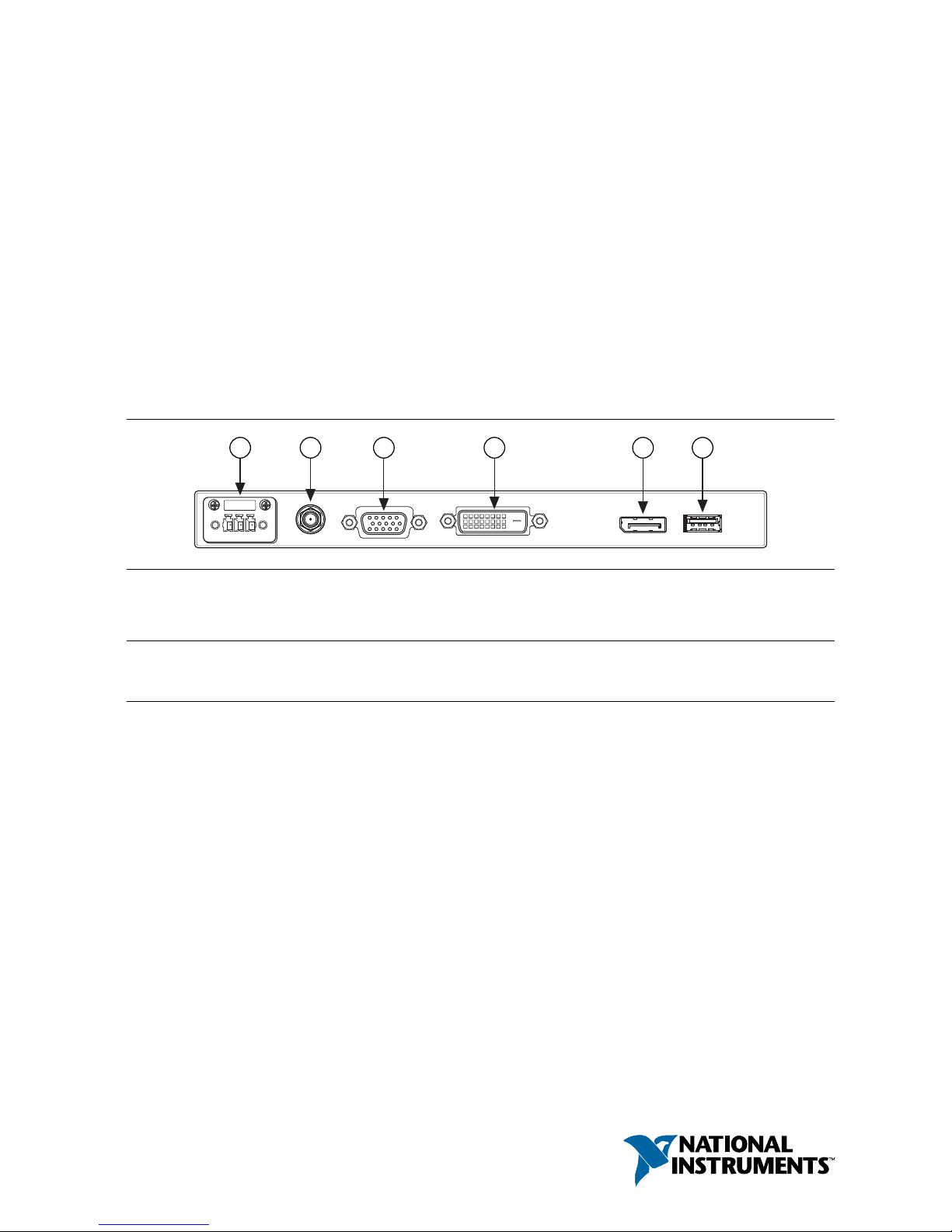
Figure 1. NI TSM-101x Connector Panel
1 2 3 4 5 6
1. 9 to 36 V terminal block
2. 9 to 36 V lockable DC jack
3. VGA port
4. DVI-D port
5. DisplayPort connector
6. USB port
Contents
Safety Guidelines...................................................................................................................... 2
General Safety Precautions............................................................................................... 2
Installation Precautions..................................................................................................... 2
Anti-Static Precautions..................................................................................................... 3
Maintenance and Cleaning................................................................................................3
Verifying the Kit Contents........................................................................................................ 3
Optional Accessories.........................................................................................................4
Installing Software Drivers....................................................................................................... 4
Supported Operating Systems...........................................................................................4
Selecting Touch Screen Modality on Windows................................................................4
Enabling the Embedded UI on NI Linux Real-Time........................................................ 6
Connecting the NI TSM-101x to Power................................................................................... 6
Wiring the Terminal Block................................................................................................6
Connecting an Adapter to the Power Jack........................................................................ 7
Page 2

Mounting the Monitor...............................................................................................................7
Dimensions........................................................................................................................7
Panel Mounting............................................................................................................... 10
Cabinet or Rack Mounting.............................................................................................. 11
Mounting to a Monitor Stand..........................................................................................12
Mounting to a Monitor Arm............................................................................................12
Mounting with the V-Mount Kit..................................................................................... 13
NI TSM-101x Features........................................................................................................... 13
9 to 36 V Terminal Block................................................................................................13
VGA Connector.............................................................................................................. 13
DVI-D Connector............................................................................................................14
DisplayPort Connector....................................................................................................15
USB for Touch Panel Connector.....................................................................................16
Display Panel Keypad.....................................................................................................17
Software Configuration...........................................................................................................17
Image Menu.................................................................................................................... 17
Display Menu..................................................................................................................17
System Menu...................................................................................................................18
Input Menu......................................................................................................................18
Safety Guidelines
General Safety Precautions
Caution Before installing and operating the NI TSM-101x monitor, read these
safety instructions carefully.
• Disconnect all power from the monitor when installing or moving the monitor.
• Do not apply voltage levels that exceed the specified voltage range.
• Do not drop or insert any objects into the ventilation openings of the monitor.
• If considerable amounts of dust, water, or fluids enter the monitor, turn off the power
supply immediately, disconnect the power cord, and contact National Instruments.
• Do not strike or exert excessive force on the LCD panel.
• Do not drop or the monitor.
• Do not touch the LCD panel with a sharp object.
Installation Precautions
• The NI TSM-101x monitor may require at least two people to mount due to its weight.
• Disconnect all power to the monitor during installation.
• Position the power cord so that it cannot be stepped on. Do not place anything over the
power cord.
• Ensure the monitor is located near an easily accessible power outlet.
• Only qualified personnel should install and operate the monitor.
• Leave at least 50 mm (0.04 in.) of clearance around the monitor to prevent overheating.
• Do not overload the voltage feeds. Provide external overcharge protection as per the label
on the back of the monitor.
2 | ni.com | NI TSM-101x User Manual
Page 3
Anti-Static Precautions
Caution Failure to follow these precautions may result in permanent damage to the
monitor and severe injury to the user.
Electrostatic discharge (ESD) can cause serious damage to electronic components. Dry
climates are especially susceptible to ESD. It is critical that whenever qualified personnel open
the NI TSM-101x monitor and handle the electrical components, they adhere to the following
anti-static precautions.
• Wear an anti-static wristband to help prevent ESD from damaging any electrical
component.
• Before handling any electrical component, touch any grounded conducting material.
Touch grounded conducting materials frequently while handling an electrical component.
• When configuring or working with an electrical component, place it on an anti-static pad.
• Handle electrical components by the edges only.
Maintenance and Cleaning
Note Take the following precautions prior to cleaning any part or component of the
monitor.
• Turn the monitor off before cleaning.
• Never spray or squirt liquids directly onto any components except the LCD panel. To
clean the LCD panel, gently wipe it with a piece of soft dry cloth or a slightly moistened
cloth.
• Keep fluids away from the monitor interior. The interior of the monitor does not require
cleaning.
Cleaning Tools
Use the following tools to clean the monitor.
• Cloth
• Water or rubbing alcohol
• Vacuum cleaner
• Cotton swabs moistened with rubbing alcohol or water
• Foam swabs
Verifying the Kit Contents
Verify that the following components are included in the NI TSM-101x kit.
Note Do not remove the plastic cover over the LCD screen until the NI TSM-101x
is properly installed.
• Touch Screen Stylus
• USB A-to-A Cable
• RS-232 Cable
NI TSM-101x User Manual | © National Instruments | 3
Page 4
If any of the items on the packing list are missing or damaged, contact National Instruments
immediately.
Optional Accessories
Table 1. Optional accessories for the NI TSM-101x monitor
Accessory NI TSM-1012 NI TSM-1015 NI TSM-1017
Arm 783674-01
Stand 783672-01 783673-01
V-Mount Kit 783675-01 —
Panel Mount Kit 783668-01
Rack Mount Kit 783669-01 783670-01 783671-01
Installing Software Drivers
The touch panel driver enables the NI TSM-101x monitor to communicate directly with the
host machine. The driver emulates configurable left and right mouse button functions via the
touch panel interface.
Supported Operating Systems
The touch panel driver supports the following operating systems:
• Microsoft Windows
– Microsoft Windows 2000
– Microsoft Windows XP
– Microsoft Windows 2003
– Microsoft Windows 2008
– Microsoft Windows Vista
– Microsoft Windows 7
– Microsoft Windows 8
– Microsoft Windows 10
• NI Linux Real-Time
Selecting Touch Screen Modality on Windows
The NI TSM-101x monitor supports touch screen modality through an RS-232 or a USB
connection. Connect either the RS-232 or the USB to the appropriate connector on the host
machine before installing the driver.
Note The default touch screen interface is USB. The RS-232 is optional for
resistive touch ATO.
4 | ni.com | NI TSM-101x User Manual
Page 5

Installing the Touch Panel Driver on Windows
Take the following steps to download and install the touch panel driver after the NI TSM-101x
monitor is connected to a computer.
1. Go to http://www.salt.com.tw/en/service-support/downloads/software.
2. Click the button to confirm the license agreement.
3. Select PenMount 6000 USB or PenMount 6000 RS-232 from the Controller pull-down
menu.
4. Select Windows Desktop from the Operating System pull-down menu.
5. Click the Search button.
6. Click the link in the Driver Title column to download the installer package.
7. Double-click Setup to make the welcome screen appear.
8. Click Next.
9. Click I Agree to accept the license agreement.
10. The Choose Install Location screen appears. Browse to a Destination Folder and click
Install.
11. When the installation is complete, click Finish.
Changing Touch Screen Modality on Windows
Take the following steps to change the touch screen modality from USB to RS-232 or vice
versa.
1. Uninstall the PenMount 6000 touch screen driver.
2. Remove the USB or RS-232 cable.
3. Connect the monitor with the new cable.
4. Download and install the correct PenMount 6000 driver.
Calibrating the Touch Screen on Windows
Take the following steps to calibrate the motion of the touch screen cursor with a touch screen
pen or finger.
1. Ensure the monitor is properly connected through an RS-232 or USB cable.
2. Ensure the touch screen driver is properly installed.
3. Click the PenMount icon in the bottom left corner of the screen, as shown the following
figure, and select Control Panel.
Figure 2. The PenMount Icon
4. The Control Panel dialog box appears. Double-click the PenMount 6000 icon on the
Device tab.
5. The calibration screen appears. Select the Standard Calibration button.
NI TSM-101x User Manual | © National Instruments | 5
Page 6
6. Follow the onscreen instructions. Touch the screen at the five specified points to
calibrate.
Enabling the Embedded UI on NI Linux Real-Time
The NI TSM-101x monitor requires a USB connection for touch-screen modality on NI Linux
Real-Time targets.
Note NI Linux Real-Time does not support RS-232 touch screen modality.
Use a USB cable to connect the monitor to the target and complete the following steps to
enable touch screen modality.
Installing the Touch Panel Driver on NI Linux Real-Time
1. Install the recommended software set on the target.
a) In MAX, expand Remote Systems in the configuration tree, then expand the RT
target by clicking the arrow beside it.
b) Select Software.
c) Click Add/Remove Software at the top of the Software tab to launch the LabVIEW
Real-Time Software Wizard.
d) Select a recommended software set to install. Click Next. MAX displays installation
progress, and restarts the target.
2. Select the Enable Embedded UI checkbox in MAX.
a) Expand Remote Systems in the configuration tree, then select the RT target.
b) Place a check in the Enable Embedded UI checkbox.
c) Click Save, then select Yes when prompted to restart the target.
Calibrating the Touch Screen on NI Linux Real-Time
The touch screen may be out of calibration on first use. Visit ni.com/info and enter the Info
Code CalibrateTouchScreenLinuxRT for information about calibrating the
NI TSM-101x touch screen on an RT target.
Connecting the NI TSM-101x to Power
Caution You must use a UL Listed ITE power supply marked LPS with the
NI TSM-101x.
Wiring the Terminal Block
Connect the leads of the 9 to 36 V DC power supply into the terminal block.
Caution To ensure the specified EMC performance, the length of all power wiring
must not exceed 3 m (10 ft).
Use wire that meets the requirements in the device specifications. Attach the power and
ground wires to the correct sockets of the connector as shown in the following figure.
Connect earth ground to the grounding electrode system of your facility using a method
appropriate for the application.
6 | ni.com | NI TSM-101x User Manual
Page 7

Figure 3. Wiring the Three-Pin Power Connector
9V~36VGND
CONNECT TO
EARTH GROUND
9V~36V DC
POWER INPUT
Connecting an Adapter to the Power Jack
The monitor can be powered through the lockable 9-36 V DC jack. You must use an adapter
with a locking connector that meets the requirements in the device specifications.
Mounting the Monitor
The NI TSM-101x monitor can be mounted in a panel, cabinet, rack, wall, or on a monitor arm
or stand.
Installation requires a Phillips screwdriver and may require additional accessories.
Caution When mounting, do not overtighten the retention screws.
Dimensions
The following figures show the dimensions for the three models of NI TSM-101x.
NI TSM-101x User Manual | © National Instruments | 7
Page 8

Figure 4. NI TSM-1012 Dimensions
b b
b
b
b
b
161.10 mm
210.60 mm
248.00 mm
4-RIO
262.20 mm
40.50 mm
16.80 mm
10.30 mm
186.40 mm
322.20 mm
32.60 mm
8 | ni.com | NI TSM-101x User Manual
Page 9

Figure 5. NI TSM-1015 Dimensions
c c
c
c
c
c
378.50 mm
306.00 mm
13-H3-COUNTERSUNK
43.20 mm
19.50 mm
230.00 mm
303.00 mm
NI TSM-101x User Manual | © National Instruments | 9
Page 10

Figure 6. NI TSM-1017 Dimensions
341.40 mm
340.00 mm
49.30 mm
374.30 mm
408.40 mm
4-RIO
Panel Mounting
The NI TSM-101x monitor has a series of mounting slots on the top and bottom panel, and
requires nine mounting clamps to mount to a panel.
Take the following steps to mount the NI TSM-101x to a panel:
1. Cut out a section of the panel that corresponds to the dimensions of the rear panel of the
monitor as shown in the following table.
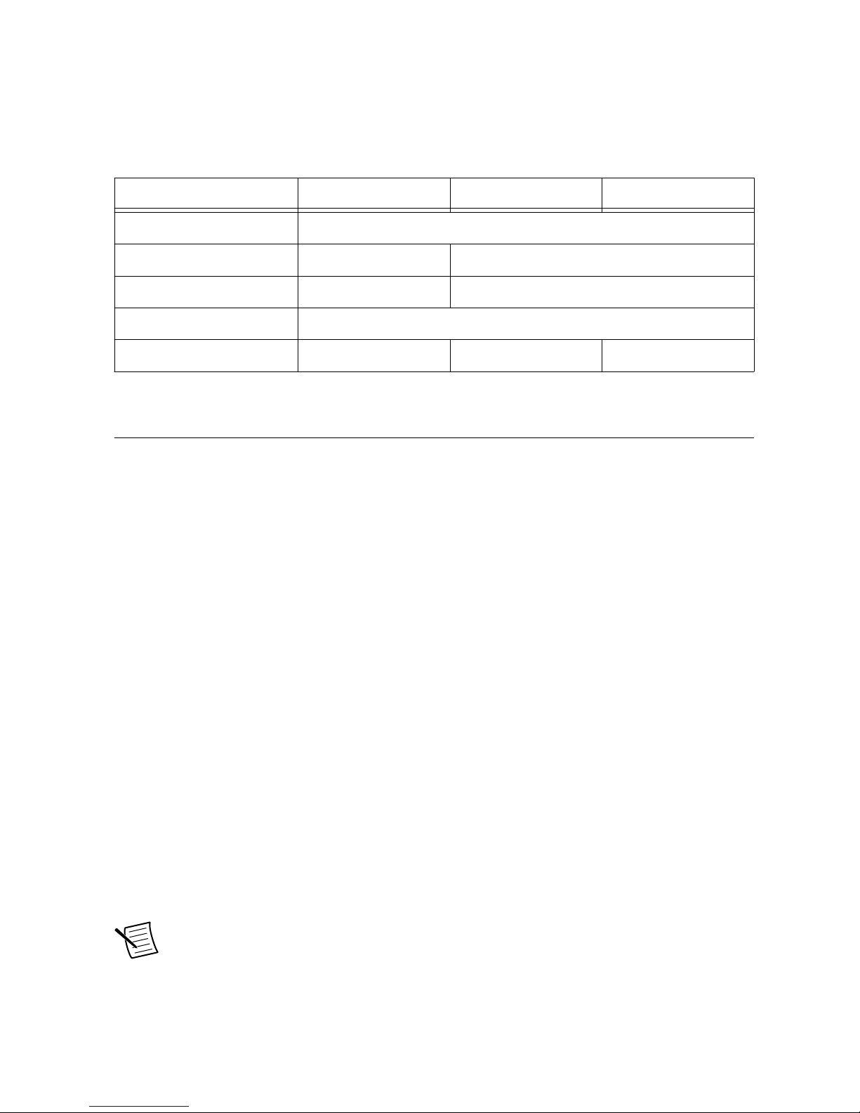
Table 2. Suggested Cutout Dimensions
Model Height Width
NI TSM-1012 243.8 mm (9.60 in.) 303.8 mm (11.96 in.)
NI TSM-1015 284.6 mm (11.20 in.) 360.1 mm (14.18 in.)
NI TSM-1017 323.0 mm (12.72 in.) 390.0 mm (15.35 in.)
2. Slide the monitor through the cutout until the aluminum frame is flush against the panel.
3. Secure the panel mounting brackets to the rear of the monitor. Insert the panel mounting
clamps into the holes along the two edges of the panel mounting brackets. The following
figure shows the panel mounting clamp positions.
10 | ni.com | NI TSM-101x User Manual
Page 11

Figure 7. Panel Mounting Clamp Positions
4. Use a Phillips screwdriver to tighten the screws that pass through the panel mounting
clamps until the plastic caps at the front of the screws are firmly secured to the panel.
Cabinet or Rack Mounting
The back of the metal frame around the monitor has retention screw holes for a cabinet or rack
installation bracket. Take the following steps to mount the NI TSM-101x monitor into a
cabinet or rack.
1. Slide the monitor through the cabinet or rack bracket until the rear side of the monitor
frame is flush against the front of the bracket.
2. Secure the panel mounting bracket to the rear of the monitor. Insert the panel mounting
clamps into the holes along the edges of the monitor, as shown in the following figure.
3. Use a Phillips screwdriver to tighten the screws that pass through the panel mounting
clamps. Secure the plastic caps at the front of the screws to the panel.
4. Slide the monitor with the attached bracket into a rack or cabinet.
5. Insert and tighten the retention screws to secure the system into a cabinet or rack as
shown in the following figure.
NI TSM-101x User Manual | © National Instruments | 11
Page 12

Figure 8. Securing the Cabinet or Rack Bracket
Mounting to a Monitor Stand
The NI TSM-101x monitor has standard Video Electronics Standards Association (VESA)
mounting holes in the rear panel. The holes are designed for M4 screws and set at 100.0 mm ×
100.0 mm (3.94 in. × 3.94 in.) apart.
The monitor stand mounting plate has a matching VESA hole pattern. Take the following steps
to mount the NI TSM-101x monitor onto a stand.
1. Align the threaded holes on the monitor rear panel with the screw holes on the monitor
stand mounting plate.
2. Secure the monitor to the stand with the supplied retention screws.
Mounting to a Monitor Arm
The NI TSM-101x monitor has standard Video Electronics Standards Association (VESA)
mounting holes in the rear panel. The holes are designed for M4 screws and set at 100.0 mm ×
100.0 mm (3.94 in. × 3.94 in.) apart.
The monitor arm mounting plate has a matching VESA hole pattern. Take the following steps
to mount the monitor to a monitor arm:
1. Align the threaded holes on the monitor rear panel with the screw holes on the monitor
arm mounting plate.
2. Secure the monitor to the arm with the supplied retention screws.
12 | ni.com | NI TSM-101x User Manual
Page 13

Mounting with the V-Mount Kit
You can use the V-Mount Kit to mount the NI TSM-1012 to a wall, ceiling, desk, or other
surface. The V-Mount has a 0 to 90 degree adjustable hinge to optimize the viewing angle of
the monitor.
Note The V-Mount is compatible only with the NI TSM-1012.
Take the following steps to mount the NI TSM-1012 with the V-Mount Kit.
1. Mark the locations of the four V-Mount retention screw holes on the mounting surface.
2. Align the VESA mounting holes in the V-Mount with the mounting holes in the rear of
the monitor.
3. Insert retention screws through the VESA mounting holes to secure the V-Mount to the
monitor.
Note The VESA holes on the monitor are designed for M4 screws and set at
100.0 mm × 100.0 mm (3.94 in. × 3.94 in.) apart.
4. Secure the V-Mount and monitor to the surface with retention screws in the locations you
marked in step 1.
NI TSM-101x Features
9 to 36 V Terminal Block
The 9 to 36 V DC terminal block has an earth ground socket, a ground socket, and three
terminals for 9 to 36 V inputs.
Figure 9. 3-pin Terminal Block
9V~36VGND
CONNECT TO
EARTH GROUND
9V~36V DC
POWER INPUT
VGA Connector
The VGA connector connects VGA video output from the host machine into the monitor. The
pins on the connector have the standard pin numbering configuration for a VGA connector.
NI TSM-101x User Manual | © National Instruments | 13
Page 14

Table 3. VGA Connector Pinouts
Pin Description
1 RED
2 GREEN
3 BLUE
4 NC
5 GROUND
6 GROUND
7 GROUND
8 GROUND
9 NC
10 GROUND
11 NC
12 DDCDAT
13 HSYNC
14 VSYNC
15 DDCCLK
DVI-D Connector
The DVI connector connects to a display device with DVI interface. The pins on the connector
have the standard pin numbering configuration for a DVI-D connector.
Table 4. DVI-D Connector Pinouts
Pin Description
1 RX2-
2 RX2+
3 GND
4 NC
5 NC
6 DVI-SCL
7 DVI-SDA
14 | ni.com | NI TSM-101x User Manual
Page 15

Table 4. DVI-D Connector Pinouts (Continued)
Pin Description
8 NC
9 RX1-
10 RX1+
11 GND
12 NC
13 NC
14 DVI-5V
15 GND
16 HOT-PLUG
17 RX0-
18 RXO+
19 GND
20 NC
21 NC
22 GND
23 RXC-
24 RXC-
DisplayPort Connector
The DisplayPort connector transmits a digital signal to compatible DisplayPort devices. The
pins on the connector have the standard pin numbering configuration for a DisplayPort
connector.
Table 5. DisplayPort Connector Pinouts
Pin Description
1 ML_L3N
2 GND
3 ML_L3P
4 ML_L2N
NI TSM-101x User Manual | © National Instruments | 15
Page 16

Table 5. DisplayPort Connector Pinouts (Continued)
Pin Description
5 GND
6 ML_L2P
7 ML_L1N
8 GND
9 ML_L1P
10 ML_L0N
11 GND
12 ML_L0P
13 GND
14 GND
15 C_DDI0_DP_AUXP
16 GND
17 C_DDI0_DP_AUXN
18 C_DDI0_DP_HPD
19 GND
20 VCC
21 GND
22 GND
23 GND
24 GND
USB for Touch Panel Connector
The USB touch panel connector enables touch screen modality from the monitor to the host
machine. The pins on the connector have the standard pin numbering configuration for a USBA connector.
16 | ni.com | NI TSM-101x User Manual
Page 17

Table 6. USB Connector Pinouts
Pin Description
1 VCC
2 USB20_N11
3 USB20_P11
4 GND
Display Panel Keypad
The NI TSM-101x monitor has a small keypad on the rear panel. Use this keypad to navigate
the onscreen menus, turn the screen on and off, and auto-adjust the image and display settings.
Software Configuration
Image Menu
The following image menu options are listed in the order they appear onscreen. Grayed out
options do not appear in the list.
• Brightness—Adjusts the brightness of the screen.
• Contrast—Adjusts the contrast of the screen. Adjusting this value too high or too low
worsens the image quality.
• Sharpness—Softens the edges around objects on the screen.
• Color—Provides the following options for color settings:
– Auto—Automatically adjusts the color settings
– Color Temp—Adjusts the following settings:
• 5000k—National Television System Committee (NTSC) standard Kelvin
• 6500k—NTSC standard Kelvin
• 9300k—NTSC standard Kelvin
• User—Adjusts the balance between red, green, and blue color hues.
Display Menu
The following display menu options are listed in the order they appear onscreen.
• Auto Adjust—Automatically adjusts the LCD screen position.
• Phase—Adjusts the input signal (analog only).
• Clock—Adjusts the dot clock position.
• Display Position—Adjusts the Gamma.
NI TSM-101x User Manual | © National Instruments | 17
Page 18

System Menu
The following system menu options are listed in the order they appear onscreen.
• Input—Selects which input device to use.
• OSD Settings—Provides the following options for onscreen display (OSD)
configuration:
– Timer—Specifies how many seconds the screen stays on after it is unattended.
– Rotation—Adjusts the angle at which the image is rotated on the screen.
– Position—Adjusts the image position on the screen
– Transparency—Adjusts the transparency of the menu background.
Input Menu
The following input menu options are listed in the order they appear onscreen.
• Display Port—Selects the DisplayPort connector as the input.
• VGA—Selects the VGA connector as the input.
• DVI/HDMI—Selects the DVI/HDMI as the input.
• autoscan—Automatically selects the input device to use.
Information is subject to change without notice. Refer to the NI Trademarks and Logo Guidelines at ni.com/trademarks for
information on NI trademarks. Other product and company names mentioned herein are trademarks or trade names of their
respective companies. For patents covering NI products/technology, refer to the appropriate location: Help»Patents in your
software, the patents.txt file on your media, or the National Instruments Patent Notice at ni.com/patents. You can find
information about end-user license agreements (EULAs) and third-party legal notices in the readme file for your NI product. Refer
to the Export Compliance Information at ni.com/legal/export-compliance for the NI global trade compliance policy and how
to obtain relevant HTS codes, ECCNs, and other import/export data. NI MAKES NO EXPRESS OR IMPLIED WARRANTIES AS
TO THE ACCURACY OF THE INFORMATION CONTAINED HEREIN AND SHALL NOT BE LIABLE FOR ANY ERRORS. U.S.
Government Customers: The data contained in this manual was developed at private expense and is subject to the applicable
limited rights and restricted data rights as set forth in FAR 52.227-14, DFAR 252.227-7014, and DFAR 252.227-7015.
© 2014—2018 National Instruments. All rights reserved.
374647D-01 April 27, 2018
 Loading...