

Page 1
INSTALLATION INSTRUCTIONS
NI TB-2631
Terminal Block for the NI PXI-2530
Ρ΅νιϋΠȂུࢊβȜΐ܄ȃ
This guide describes how to install and connect signals to the
National Instruments TB-2631 terminal block to configure the PXI-2530
as a:
• 4x32 1-wire matrix
• 4x16 2-wire matrix
Refer to the NI Switches Getting Started Guide to determine when to install
the terminal block.
Introduction
The TB-2631 terminal block installs in front of the PXI-2530 switch
module. The TB-2631 has screw terminals to connect signals to the switch.
Screw terminals for the trigger input and trigger output signals also are
available.
Conventions
The following conventions are used in this guide:
» The » symbol leads you through nested menu items and dialog box options
to a final action. The sequence File»Page Setup»Options directs you to
pull down the File menu, select the Page Setup item, and select Options
from the last dialog box.
This icon denotes a note, which alerts you to important information.
This icon denotes a caution, which advises you of precautions to take to
avoid injury, data loss, or a system crash.
Page 2
bold Bold text denotes items that you must select or click in the software, such
as menu items and dialog box options. Bold text also denotes parameter
names.
italic Italic text denotes variables, emphasis, a cross reference, or an introduction
to a key concept. This font also denotes text that is a placeholder for a word
or value that you must supply.
monospace Text in this font denotes text or characters that you should enter from the
keyboard, sections of code, programming examples, and syntax examples.
This font is also used for the proper names of disk drives, paths, directories,
programs, subprograms, subroutines, device names, functions, operations,
variables, filenames and extensions, and code excerpts.
1. Unpack the Terminal Block
To avoid damage when you handle the terminal block, take the following
precautions:
Caution Never touch the exposed pins of connectors.
• Ground yourself using a grounding strap or by touching a grounded
object.
• Touch the antistatic package to a metal part of the chassis before you
remove the terminal block from the package.
Remove the terminal block from the package and inspect the terminal block
for loose components or any sign of damage. Notify NI if the terminal
block appears damaged in any way. Do not install a damaged terminal
block on a switch module.
Store the terminal block in the antistatic package when not in use.
2. Verify the Components
Make sure you have the following:
❑ TB-2631 terminal block
❑ PXI chassis
❑ PXI-2530 switch module
❑ 1/8 inch flathead screwdriver
NI TB-2631 Installation Instructions 2 ni.com
Page 3

3. Connect Signals
To connect signals to the terminal block, complete the following steps:
1. Remove the terminal block top cover screws with a flathead
screwdriver.
2. Gently lift the terminal block top cover off the terminal block.
3. Loosen the two screws on the strain-relief bar, leaving plenty of space
for the signal cables.
4. Prepare the signal cable by stripping the insulation no more than 3/16
of an inch.
5. Pull the signal cables through the strain-relief opening shown in
Figure 1.
6. Connect the cables to the terminals by inserting the stripped end of the
cable into the terminal. Secure the connection by tightening the screw
for each terminal. When connecting the signals, refer to the connection
diagram in Figure 2.
Note When connecting signals to the TB-2631, refer to Tables 1 and 2 to determine where
to connect signals for the chosen topology.
7. Tighten the two screws on the strain-relief bar, securing the signal
cables.
8. Replace the terminal block top cover to the terminal block.
9. Secure the terminal block top cover with the top cover screws.
© National Instruments Corporation 3 NI TB-2631 Installation Instructions
Page 4
8
7
8
9
10
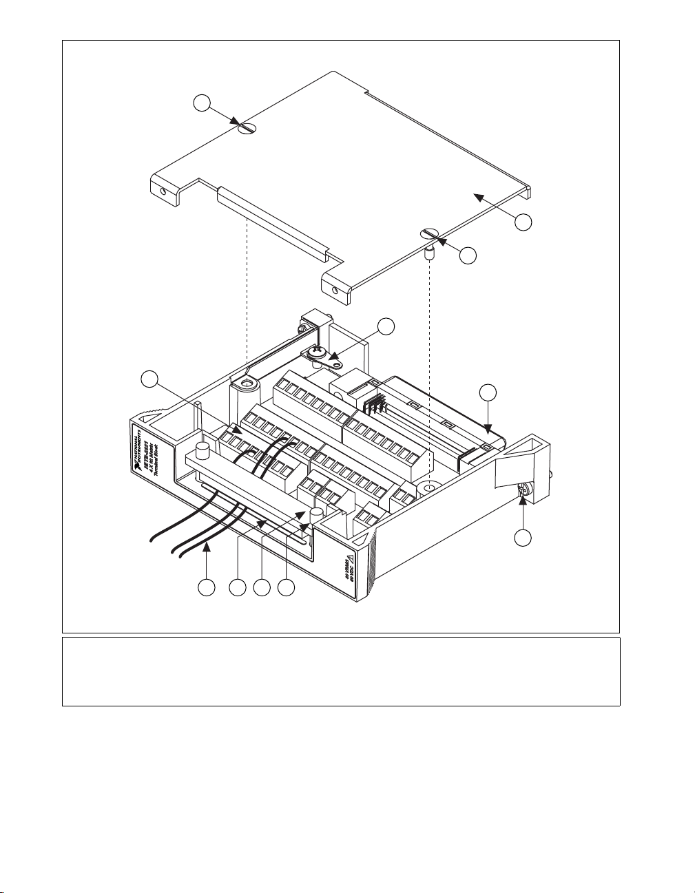
1 Signal Cables
2 Strain-Relief Opening
3 Strain-Relief Bar
4 Strain-Relief Screw
5 Chassis Screws
1 4
2 3
6
5
6 Rear Connector
7 Terminal Block Top Cover
8 Top Cover Screws
9 Safety Ground Lug
10 Screw Terminals
Figure 1. TB-2631 Terminal Block
NI TB-2631 Installation Instructions 4 ni.com
Page 5

COLUMNS
0
ROWS
0
1
NI TB-2631 Screw Terminal Reference
2
3
4
5
6
7
10
2
3
1-WIRE
REFERENCE
1
2
3
4
5
6
7
8
9
10
11
12
13
14
15
16
17
18
19
20
21
22
23
24
25
26
27
28
29
30
31
60 VDC / 30 VRMS MAX
0.4 A MAX
176 POSITION CONNECTOR
GND
TRIGOUT
GND
TRIGIN
+5V MAX
Figure 2. TB-2631 Terminal Reference
© National Instruments Corporation 5 NI TB-2631 Installation Instructions
Page 6

Table 1. 4x32, 1-Wire Topology Terminal Mapping
Software Name Hardware Name Software Name Hardware Name
r0 ROW 0 c14 COLUMN 14
r1 ROW 2 c15 COLUMN 15
r2 ROW 4 c16 COLUMN 16
r3 ROW 6 c17 COLUMN 17
c0 COLUMN 0 c18 COLUMN 18
c1 COLUMN 1 c19 COLUMN 19
c2 COLUMN 2 c20 COLUMN 20
c3 COLUMN 3 c21 COLUMN 21
c4 COLUMN 4 c22 COLUMN 22
c5 COLUMN 5 c23 COLUMN 23
c6 COLUMN 6 c24 COLUMN 24
c7 COLUMN 7 c25 COLUMN 25
c8 COLUMN 8 c26 COLUMN 26
c9 COLUMN 9 c27 COLUMN 27
c10 COLUMN 10 c28 COLUMN 28
c11 COLUMN 11 c29 COLUMN 29
c12 COLUMN 12 c30 COLUMN 30
c13 COLUMN 13 c31 COLUMN 31
NI TB-2631 Installation Instructions 6 ni.com
Page 7

Table 2. 4x16, 2-Wire Topology Terminal Mapping
Software
Name
Hardware Name
+ – + –
Software
Name
Hardware Name
r0 ROW 0 ROW 1 c6 COLUMN 6 COLUMN 22
r1 ROW 2 ROW 3 c7 COLUMN 7 COLUMN 23
r2 ROW 4 ROW 5 c8 COLUMN 8 COLUMN 24
r3 ROW 6 ROW 7 c9 COLUMN 9 COLUMN 25
c0 COLUMN 0 COLUMN 16 c10 COLUMN 10 COLUMN 26
c1 COLUMN 1 COLUMN 17 c11 COLUMN 11 COLUMN 27
c2 COLUMN 2 COLUMN 18 c12 COLUMN 12 COLUMN 28
c3 COLUMN 3 COLUMN 19 c13 COLUMN 13 COLUMN 29
c4 COLUMN 4 COLUMN 20 c14 COLUMN 14 COLUMN 30
c5 COLUMN 5 COLUMN 21 c15 COLUMN 15 COLUMN 31
© National Instruments Corporation 7 NI TB-2631 Installation Instructions
Page 8
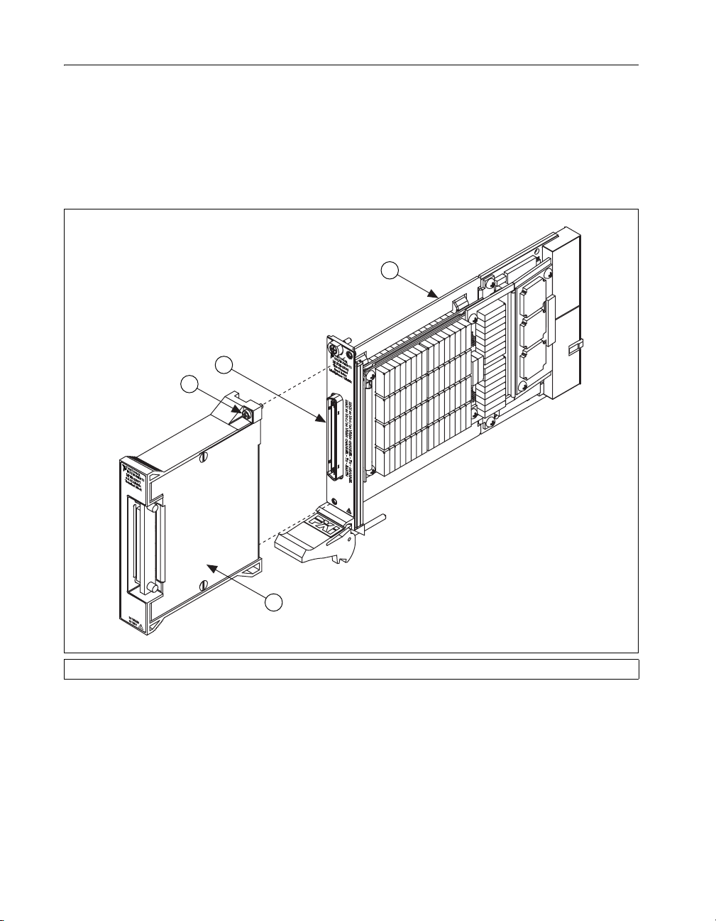
4. Install the Terminal Block
To connect the TB-2631 terminal block to the PXI-2530 front panel,
complete the following steps (the PXI-2530 should already be installed in
a PXI chassis):
1. Plug the TB-2631 on to the front connector of the PXI-2530.
2. Tighten the top and bottom chassis screws on the back of the terminal
block rear panel to hold it securely in place.
2
1
3
4
1 Chassis Screw 2 Front Connector 3 PXI-2530 4 TB-2631
Figure 3. Installing the TB-2631 Terminal Block
NI TB-2631 Installation Instructions 8 ni.com
Page 9

Compliance and Certifications
Safety
This product is designed to meet the requirements of the following
standards of safety for electrical equipment for measurement, control,
and laboratory use:
• IEC 61010-1, EN 61010-1
• UL 3111-1, UL 61010B-1
• CAN/CSA C22.2 No. 1010.1
Note For UL and other safety certifications, refer to the product label, or visit ni.com/
certification
in the Certification column.
Electromagnetic Compatibility
, search by model number or product line, and click the appropriate link
Emissions ............................................... EN 55011 Class A at 10 m
Immunity................................................ EN 61326:1997 + A2:2001,
EMC/EMI............................................... CE, C-Tick, and FCC Part 15
FCC Part 15A above 1 GHz
Table 1
(Class A) Compliant
Note For EMC compliance, you must operate this device with shielded cabling.
CE Compliance
This product meets the essential requirements of applicable European
Directives, as amended for CE marking, as follows:
Low-Voltage Directive (safety) ............. 73/23/EEC
Electromagnetic Compatibility
Directive (EMC) .................................... 89/336/EEC
Note Refer to the Declaration of Conformity (DoC) for this product for any additional
regulatory compliance information. To obtain the DoC for this product, visit
certification
the Certification column.
© National Instruments Corporation 9 NI TB-2631 Installation Instructions
, search by model number or product line, and clik the appropriate link in
ni.com/
Page 10

National Instruments, NI, ni.com, and LabVIEW are trademarks of National Instruments Corporation. Refer to the Terms of Use section on
ni.com/legal for more information about National Instruments trademarks. Other product and company names mentioned herein are
trademarks or trade names of their respective companies. For patents covering National Instruments products, refer to the appropriate location:
Help»Patents in your software, the patents.txt file on your CD, or ni.com/patents.
© 2003–2007 National Instruments Corporation. All rights reserved.
373685B Nov07
 Loading...