

Page 1

Artisan Technology Group is your source for quality
new and certied-used/pre-owned equipment
• FAST SHIPPING AND
DELIVERY
• TENS OF THOUSANDS OF
IN-STOCK ITEMS
• EQUIPMENT DEMOS
• HUNDREDS OF
MANUFACTURERS
SUPPORTED
• LEASING/MONTHLY
RENTALS
• ITAR CERTIFIED
SECURE ASSET SOLUTIONS
SERVICE CENTER REPAIRS
Experienced engineers and technicians on staff
at our full-service, in-house repair center
Instra
Remotely inspect equipment before purchasing with
our interactive website at www.instraview.com
Contact us: (888) 88-SOURCE | sales@artisantg.com | www.artisantg.com
SM
REMOTE INSPECTION
View
WE BUY USED EQUIPMENT
Sell your excess, underutilized, and idle used equipment
We also offer credit for buy-backs and trade-ins
www.artisantg.com/WeBuyEquipment
LOOKING FOR MORE INFORMATION?
Visit us on the web at www.artisantg.com for more
information on price quotations, drivers, technical
specications, manuals, and documentation
Page 2

GETTING STARTED GUIDE
NI PXIe-4080/4081/4082
1.8 MS/s Digital Multimeter
Note Before you begin, install and configure your chassis and controller.
This document explains how to install, configure, and test the NI 4080/4081/4082. The
NI 4080/4081/4082 is a digital multimeter that ships with NI-DMM, which you use to
program the device.
To access NI 4080/4081/4082 documentation, navigate to Start»All Programs»National
Instruments»NI-DMM Documentation.
Caution The protection provided by this device may be impaired if the device is
used in a manner not specified in this document.
Contents
Electromagnetic Compatibility Guidelines...............................................................................2
Verifying the System Requirements..........................................................................................2
Unpacking the Kit..................................................................................................................... 2
Preparing the Environment....................................................................................................... 3
Safety........................................................................................................................................ 3
Kit Contents.............................................................................................................................. 4
Other Equipment............................................................................................................... 4
Installing the Software.............................................................................................................. 4
Installing the NI 4080/4081/4082............................................................................................. 5
Hardware Front Panel Connectors............................................................................................ 6
Connecting Signals........................................................................................................... 7
Requirements for Cables and Probes...................................................................................... 10
Configuring the NI 4080/4081/4082 in MAX.........................................................................11
Programming the NI 4080/4081/4082.....................................................................................11
NI-DMM Examples........................................................................................................ 13
Troubleshooting...................................................................................................................... 14
What Should I Do if the NI 4080/4081/4082 Doesn't Appear in MAX?........................14
What Should I Do if the Module Fails the Self-Test?.....................................................15
Where to Go Next................................................................................................................... 15
Worldwide Support and Services............................................................................................ 15
Artisan Technology Group - Quality Instrumentation ... Guaranteed | (888) 88-SOURCE | www.artisantg.com
Page 3
Electromagnetic Compatibility Guidelines
This product was tested and complies with the regulatory requirements and limits for
electromagnetic compatibility (EMC) stated in the product specifications. These requirements
and limits provide reasonable protection against harmful interference when the product is
operated in the intended operational electromagnetic environment.
This product is intended for use in industrial locations. However, harmful interference may
occur in some installations, when the product is connected to a peripheral device or test object,
or if the product is used in residential or commercial areas. To minimize interference with
radio and television reception and prevent unacceptable performance degradation, install and
use this product in strict accordance with the instructions in the product documentation.
Furthermore, any changes or modifications to the product not expressly approved by National
Instruments could void your authority to operate it under your local regulatory rules.
Verifying the System Requirements
To use the NI 4080/4081/4082, your system must meet certain requirements. For more
information about minimum system requirements, recommended system, and supported
application development environments (ADEs), refer to the readme, which is available on the
software media or online at ni.com/updates.
Unpacking the Kit
Caution To prevent electrostatic discharge (ESD) from damaging the device,
ground yourself using a grounding strap or by holding a grounded object, such as
your computer chassis.
1. Touch the antistatic package to a metal part of the computer chassis.
2. Remove the device from the package and inspect the device for loose components or any
other sign of damage.
Caution Never touch the exposed pins of connectors.
Note Do not install a device if it appears damaged in any way.
3. Unpack any other items and documentation from the kit.
Store the device in the antistatic package when the device is not in use.
2 | ni.com | NI PXIe-4080/4081/4082 Getting Started Guide
Artisan Technology Group - Quality Instrumentation ... Guaranteed | (888) 88-SOURCE | www.artisantg.com
Page 4
Preparing the Environment
Ensure that the environment you are using the NI 4080/4081/4082 in meets the following
specifications.
Operating Environment
Ambient temperature range 0 °C to 55 °C (Tested in accordance with
IEC 60068-2-1 and IEC 60068-2-2. Meets
MIL-PRF-28800F Class 3 low temperature
limit and MIL-PRF-28800F Class 2 high
temperature limit.)
Relative humidity range 10% to 90%, noncondensing (Tested in
accordance with IEC 60068-2-56.)
Storage ambient temperature range -40 °C to 70 °C (Tested in accordance
with IEC 60068-2-1 and IEC 60068-2-2.)
Maximum altitude 2,000 m (800 mbar) (at 25 °C ambient
temperature)
Pollution Degree 2
Indoor use only.
Note Refer to the device specifications on ni.com/manuals for complete
specifications.
Safety
Caution Always refer to the specifications document for your device before
connecting signals. Failure to observe the specified maximum signal ratings can
cause shock, a fire hazard, or damage to the devices connected to the
NI 4080/4081/4082. NI is not liable for any damage or injuries resulting from
incorrect signal connections.
NI PXIe-4080/4081/4082 Getting Started Guide | © National Instruments | 3
Artisan Technology Group - Quality Instrumentation ... Guaranteed | (888) 88-SOURCE | www.artisantg.com
Page 5
Kit Contents
4 5
3
2
PXIe-4080
61/2 Digit DMM
1
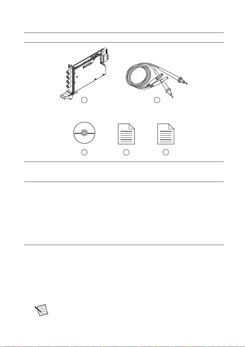
Figure 1. NI 4080/4081/4082 Kit Contents
1. NI PXIe-4080/4081/4082 Device
2. Test probes
3. Driver Software DVD
4. NI PXIe-4080/4081/4082 Getting Started Guide
(this document)
5. Maintain Forced-Air Cooling Note to Users
Other Equipment
There are several required items not included in your device kit that you need to install or
operate the NI 4080/4081/4082.
• 1/8 in. flathead screwdriver
• A PXI Express chassis with a controller and the chassis documentation
Installing the Software
You must be an Administrator to install NI software on your computer.
1. Install an ADE, such as LabVIEW or LabWindows™/CVI™.
2. Insert the driver software media into your computer. The installer should open
automatically.
If the installation window does not appear, navigate to the drive, double-click it, and
double-click autorun.exe.
3. Follow the instructions in the installation prompts.
Note Windows users may see access and security messages during
installation. Accept the prompts to complete the installation.
4 | ni.com | NI PXIe-4080/4081/4082 Getting Started Guide
Artisan Technology Group - Quality Instrumentation ... Guaranteed | (888) 88-SOURCE | www.artisantg.com
Page 6
4. When the installer completes, select Restart in the dialog box that prompts you to restart,
NI PXIe-1062Q
123
4
5
shut down, or restart later.
Installing the NI 4080/4081/4082
Caution To prevent damage to the NI 4080/4081/4082 caused by ESD or
contamination, handle the module using the edges or the metal bracket.
1. Ensure the AC power source is connected to the chassis before installing the module.
The AC power cord grounds the chassis and protects it from electrical damage while you
install the module.
2. Power off the chassis.
3. Inspect the slot pins on the chassis backplane for any bends or damage prior to
installation. Do not install a module if the backplane is damaged.
4. Remove the black plastic covers from all the captive screws on the module front panel.
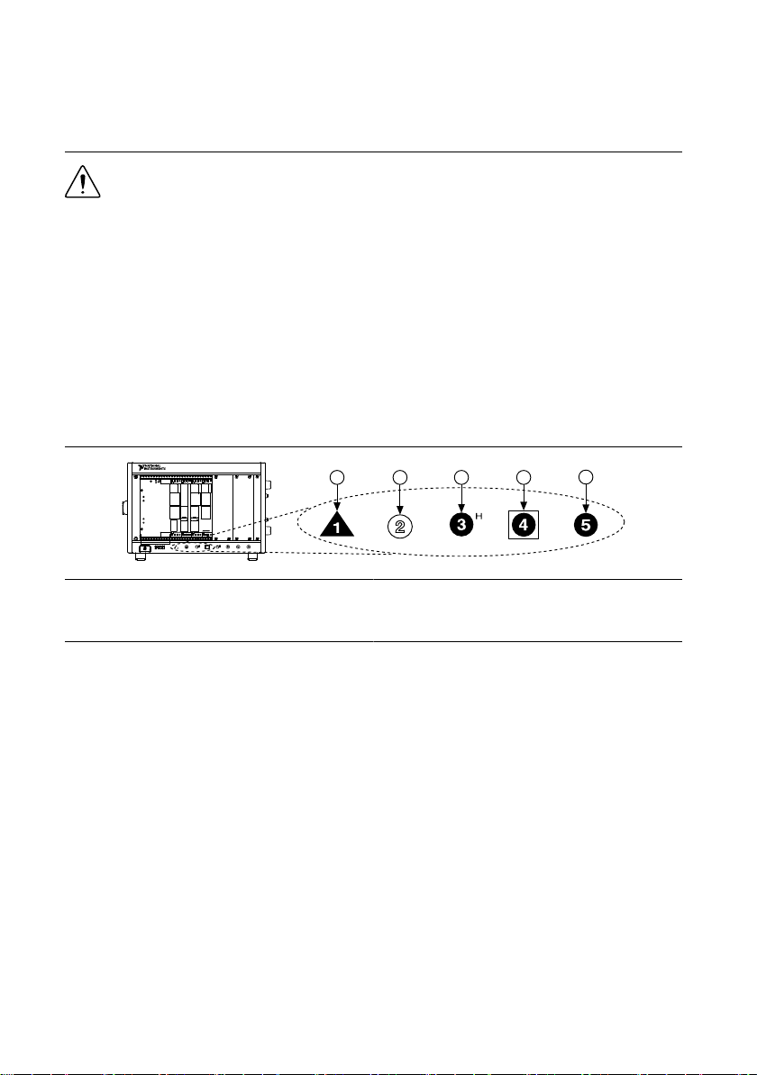
5. Identify a supported slot in the chassis. The following figure shows the symbols that
indicate the slot types.
Figure 2. Chassis Compatibility Symbols
1. PXI Express System Controller Slot
2. PXI Peripheral Slot
3. PXI Express Hybrid Peripheral Slot
4. PXI Express System Timing Slot
5. PXI Express Peripheral Slot
NI 4080/4081/4082 modules can be placed in PXI Express peripheral slots, PXI Express
hybrid peripheral slots, or PXI Express system timing slots.
6. Touch any metal part of the chassis to discharge static electricity.
7. Ensure that the ejector handle is in the downward (unlatched) position.
8. Place the module edges into the module guides at the top and bottom of the chassis. Slide
the module into the slot until it is fully inserted.
NI PXIe-4080/4081/4082 Getting Started Guide | © National Instruments | 5
Artisan Technology Group - Quality Instrumentation ... Guaranteed | (888) 88-SOURCE | www.artisantg.com
Page 7

Figure 3. Module Installation
2
3
NI PXIe-1075
1
1. Chassis
2. Hardware Module
3. Ejector Handle in Downward (Unlatched) Position
9. Latch the module in place by pulling up on the ejector handle.
10. Secure the module front panel to the chassis using the front-panel mounting screws.
Note Tightening the top and bottom mounting screws increases mechanical
stability and also electrically connects the front panel to the chassis, which can
improve the signal quality and electromagnetic performance.
11. Cover all empty slots using EMC filler panels or fill using slot blockers to maximize
cooling air flow, depending on your application.
12. Power on the chassis.
Hardware Front Panel Connectors
Refer to the following figure for the NI 4080/4081/4082 front panels. The front panels have
four shrouded banana plug connectors.
6 | ni.com | NI PXIe-4080/4081/4082 Getting Started Guide
Artisan Technology Group - Quality Instrumentation ... Guaranteed | (888) 88-SOURCE | www.artisantg.com
Page 8

PXIe-4080
6½-Digit DMM
PXIe-4081
7½-Digit DMM
PXIe-4082
6½-Digit DMM
HI
HI
LO
LO
HI
HI
LO
LO
HI
HI
LO
LO
300 V
300 V CAT II 300 V CAT II
500 V CAT II
1000 V CAT I
Ω 4 W
V Ω
INPUT
V Ω
INPUT
V Ω
INPUT
MAX
500 V
MAX
300 V
MAX
MAX
AMPS AMPS AMPS
SENSE
1A
Ω 4 W
MAX
SENSE
1A
Ω 4 W
MAX
SENSE
3A
MAX
300 V
MAX
1k V
MAX
300 V
Connecting Signals
The following figures show how to connect signals to the DMM front panel connectors for
common measurements.
For more information about these common measurements, refer to the NI Digital Multimeters
Help at ni.com/manuals.
Caution Always refer to the device specifications before connecting signals.
Failure to observe the specified maximum signal ratings can cause shock, a fire
NI PXIe-4080/4081/4082 Getting Started Guide | © National Instruments | 7
Artisan Technology Group - Quality Instrumentation ... Guaranteed | (888) 88-SOURCE | www.artisantg.com
Page 9

hazard, or damage to the devices connected to the DMM. NI is not liable for any
or
AC
DC
HI
LO
HI
LO
HI
LO
HI
LO
damage or injuries resulting from incorrect signal connections.
Figure 4. DC and AC Voltage
Figure 5. DC and AC Current
8 | ni.com | NI PXIe-4080/4081/4082 Getting Started Guide
Artisan Technology Group - Quality Instrumentation ... Guaranteed | (888) 88-SOURCE | www.artisantg.com
Page 10

Figure 6. 2-Wire and 4-Wire Resistance
HI
LO
HI
LO
HI
LO
HI
LO
+
–
HI
LO
HI
LO
HI
LO
HI
LO
Note 4-wire resistance measurements use both pairs of terminals. Use the
configuration to measure low resistances accurately by eliminating the effects of
lead resistance.
Figure 7. Capacitance and Inductance
NI PXIe-4080/4081/4082 Getting Started Guide | © National Instruments | 9
Artisan Technology Group - Quality Instrumentation ... Guaranteed | (888) 88-SOURCE | www.artisantg.com
Page 11

Figure 8. Voltage Drop Across a Diode
+
–
HI
LO
HI
LO
Requirements for Cables and Probes
The DMM shipping kit contains a pair of test probes with safety banana plugs. These probes
meet international safety requirements, including UL 3111 and IEC-1010-1, for the full range
of applications supported by the DMM.
Caution Before using any probes or accessories, ensure that they meet applicable
safety requirements for the signal levels you may encounter.
Connect the test probes to the banana plug connectors on the DMM front panel using safety
banana plugs. The shrouds around the banana plugs prevent you from contacting potentially
hazardous voltages connected to the test probes. You can also connect the cable to standard,
unshrouded banana plug probes or accessories. Use unshrouded probes or accessories only
when the voltages are less than 30 Vrms and 42 Vpk, or 60 VDC.
Caution (NI 4081 users) To prevent possible safety hazards, the maximum voltage
between any of the inputs and the ground of the PXI Express chassis is 500 VDC or
500 Vrms (sine wave), except between the HI terminal and ground, where the
maximum voltage is 1,000 VDC or700 Vrms (sine wave). The maximum current the
NI 4081 can measure through the current inputs is ±3 ADC or 3 Arms.
Caution (NI 4080/4082 users) To prevent possible safety hazards, the maximum
voltage between any of the inputs and the ground of the computer is 300 VDC or
300 Vrms. The maximum current the NI 4080/4082 can measure through the current
inputs is ±1 ADC or 1 Arms.
10 | ni.com | NI PXIe-4080/4081/4082 Getting Started Guide
Artisan Technology Group - Quality Instrumentation ... Guaranteed | (888) 88-SOURCE | www.artisantg.com
Page 12

Configuring the NI 4080/4081/4082 in MAX
Use Measurement & Automation Explorer (MAX) to configure your NI hardware. MAX
informs other programs about which NI hardware products are in the system and how they are
configured. MAX is automatically installed with NI-DMM.
1. Launch MAX.
2. In the configuration tree, expand Devices and Interfaces to see the list of installed NI
hardware.
Installed modules appear under the name of their associated chassis.
3. Expand your Chassis tree item.
MAX lists all modules installed in the chassis. Your default names may vary.
Note If you do not see your module listed, press <F5> to refresh the list of
installed modules. If the module is still not listed, power off the system, ensure
the module is correctly installed, and restart.
4. Record the identifier MAX assigns to the hardware. Use this identifier when
programming the NI 4080/4081/4082.
5. Self-test the hardware by selecting the item in the configuration tree and clicking Self-
Test in the MAX toolbar.
The MAX self-test performs a basic verification of hardware resources.
Programming the NI 4080/4081/4082
You can acquire data interactively using the NI-DMM Soft Front Panel (SFP), or you can use
the NI-DMM instrument driver to program your device in the supported ADE of your choice.
NI PXIe-4080/4081/4082 Getting Started Guide | © National Instruments | 11
Artisan Technology Group - Quality Instrumentation ... Guaranteed | (888) 88-SOURCE | www.artisantg.com
Page 13

Table 1. NI-DMM Programming Options
Application Programming
Interface (API)
Location Description
NI-DMM Soft Front Panel (SFP) Available from the start
menu at Start»All
Programs»National
Instruments»NI-DMM»
NI-DMM Soft Front
Panel.
The NI-DMM SFP allows
users to take
measurements and to test
the functionality of NI
DMM devices. The
NI-DMM SFP provides an
interface that allows users
to interact with an NI
DMM as if it were a
traditional benchtop
instrument. If you have
multiple NI DMM devices,
you can run multiple
sessions of the
NI-DMM SFP
simultaneously.
12 | ni.com | NI PXIe-4080/4081/4082 Getting Started Guide
Artisan Technology Group - Quality Instrumentation ... Guaranteed | (888) 88-SOURCE | www.artisantg.com
Page 14

Table 1. NI-DMM Programming Options (Continued)
Application Programming
Interface (API)
Location Description
NI-DMM Instrument Driver LabVIEW—Available on
the LabVIEW Functions
palette at Measurement
I/O»NI-DMM.
C or LabWindows/CVI—
Available at Program
Files»IVI Foundation»
IVI»Drivers»niDMM
Microsoft Visual C/C++—
Use examples located in the
<NIDocDir>\NI-DMM
\examples directory,
where <NIDocDir> is one
of the following directories:
• Windows 8/7/Vista—
Users\Public
\Documents
\National
Instruments
• Windows XP—
Documents and
Settings\All
Users\Shared
Documents
\National
Instruments
NI-DMM configures and
operates the device
hardware and performs
basic acquisition and
measurement options
using LabVIEW VIs or
LabWindows/CVI
functions.
You can modify an
NI-DMM C example to
create an application with
Microsoft Visual C/C++.
Copy an NI-DMM
example to copy required
project settings for include
paths and library files.
Alternatively, refer to the
Using NI-DMM in Visual
C++ topic of the NI
Digital Multimeters Help
to manually add all
required include and
library files to your
project.
NI-DMM Examples
The NI Example Finder is a utility available for some ADEs that organizes examples into
categories and allows you to easily browse and search installed examples. You can see
descriptions and compatible hardware models for each example, or see all the examples
compatible with one particular hardware model.
To locate examples, refer to the following table.
NI PXIe-4080/4081/4082 Getting Started Guide | © National Instruments | 13
Artisan Technology Group - Quality Instrumentation ... Guaranteed | (888) 88-SOURCE | www.artisantg.com
Page 15

Application
Development
Environment (ADE)
Table 2. Locating NI-DMM Examples
Location
LabVIEW or
LabWindows/CVI
ANSI C or Visual Basic Locate examples in the <NIDocDir>\NI–DMM\examples
Locate examples with the NI Example Finder. Within LabVIEW
or LabWindows/CVI, select Help»Find Examples, and navigate
to Hardware Input and Output»Modular Instruments»NI-
DMM (Digital Multimeters).
directory, where <NIDocDir> is one of the following directories:
• Windows 8/7/Vista—Users\Public\Public
Documents\National Instruments
• Windows XP—Documents and Settings\All Users
\Shared Documents\National Instruments
Troubleshooting
If an issue persists after you complete a troubleshooting procedure, contact NI technical
support or visit ni.com/support.
What Should I Do if the NI 4080/4081/4082 Doesn't
Appear in MAX?
1. In the MAX configuration tree, expand Devices and Interfaces.
2. Expand the Chassis tree to see the list of installed hardware, and press <F5> to refresh
the list.
3. If the module is still not listed, power off the system, ensure that all hardware is correctly
installed, and restart the system.
4. Navigate to the Device Manager.
Operating System Description
Windows 10/8.1 Right-click the Start button, and select Device Manager.
Windows 7 Select Start»Control Panel»Device Manager.
5. If you are using a PXI or PXI Express controller, verify that a National Instruments
entry appears in the System Devices list. Reinstall NI-DMM and the module if error
conditions appear in the list. If you are using an MXI controller, right-click PCI-to-PCI
Bridge, and select Properties from the shortcut menu to verify that the bridge is enabled.
14 | ni.com | NI PXIe-4080/4081/4082 Getting Started Guide
Artisan Technology Group - Quality Instrumentation ... Guaranteed | (888) 88-SOURCE | www.artisantg.com
Page 16

What Should I Do if the Module Fails the Self-Test?
more about your products through ni.com.
*This item is also installed with the driver software.
DISCOVER
Services
ni.com/services
NI Community
ni.com/community
Support
ni.com/support
custom applications within
an application programming
interface (API).
NI-DMM Soft Front Panel
NI-DMM Instrument Driver
CREATE
Located online at ni.com/manuals Located using the NI Example Finder
NI Digital Multimeters Help*
NI-DMM Examples*
about hardware features
or review device
specifications.
LEARN
NI Digital Multimeters Help*
NI PXIe-4080 Specifications*
OR
NI PXIe-4081 Specifications*
OR
NI PXIe-4082 Specifications*
the application development
environment (ADE)
for your application.
EXPLORE
NI Digital Multimeters
ni.com/digitalmultimeters
Getting Started with
LabWindows/CVI
Getting Started with
LabVIEW
1. Restart the system.
2. Launch MAX, and perform the self-test again.
3. Power off the chassis.
4. Reinstall the failed module in a different slot.
5. Power on the chassis.
6. Perform the self-test again.
Where to Go Next
Refer to the following figure for information about other product tasks and associated
resources for those tasks.
Worldwide Support and Services
The NI website is your complete resource for technical support. At ni.com/support, you have
access to everything from troubleshooting and application development self-help resources to
email and phone assistance from NI Application Engineers.
Artisan Technology Group - Quality Instrumentation ... Guaranteed | (888) 88-SOURCE | www.artisantg.com
NI PXIe-4080/4081/4082 Getting Started Guide | © National Instruments | 15
Page 17

Visit ni.com/services for NI Factory Installation Services, repairs, extended warranty, and
other services.
Visit ni.com/register to register your NI product. Product registration facilitates technical
support and ensures that you receive important information updates from NI.
A Declaration of Conformity (DoC) is our claim of compliance with the Council of the
European Communities using the manufacturer’s declaration of conformity. This system
affords the user protection for electromagnetic compatibility (EMC) and product safety. You
can obtain the DoC for your product by visiting ni.com/certification. If your product supports
calibration, you can obtain the calibration certificate for your product at ni.com/calibration.
NI corporate headquarters is located at 11500 North Mopac Expressway, Austin, Texas,
78759-3504. NI also has offices located around the world. For telephone support in the United
States, create your service request at ni.com/support or dial 1 866 ASK MYNI (275 6964). For
telephone support outside the United States, visit the Worldwide Offices section of ni.com/
niglobal to access the branch office websites, which provide up-to-date contact information,
support phone numbers, email addresses, and current events.
Refer to the NI Trademarks and Logo Guidelines at ni.com/trademarks for information on NI trademarks. Other product and
company names mentioned herein are trademarks or trade names of their respective companies. For patents covering NI
products/technology, refer to the appropriate location: Help»Patents in your software, the patents.txt file on your media, or the
National Instruments Patent Notice at ni.com/patents. You can find information about end-user license agreements (EULAs)
and third-party legal notices in the readme file for your NI product. Refer to the Export Compliance Information at ni.com/
legal/export-compliance for the NI global trade compliance policy and how to obtain relevant HTS codes, ECCNs, and other
import/export data. NI MAKES NO EXPRESS OR IMPLIED WARRANTIES AS TO THE ACCURACY OF THE INFORMATION
CONTAINED HEREIN AND SHALL NOT BE LIABLE FOR ANY ERRORS. U.S. Government Customers: The data contained in
this manual was developed at private expense and is subject to the applicable limited rights and restricted data rights as set forth
in FAR 52.227-14, DFAR 252.227-7014, and DFAR 252.227-7015.
© 2015—2016 National Instruments. All rights reserved.
375250B-01 Oct16
Artisan Technology Group - Quality Instrumentation ... Guaranteed | (888) 88-SOURCE | www.artisantg.com
Page 18

Artisan Technology Group is your source for quality
new and certied-used/pre-owned equipment
• FAST SHIPPING AND
DELIVERY
• TENS OF THOUSANDS OF
IN-STOCK ITEMS
• EQUIPMENT DEMOS
• HUNDREDS OF
MANUFACTURERS
SUPPORTED
• LEASING/MONTHLY
RENTALS
• ITAR CERTIFIED
SECURE ASSET SOLUTIONS
SERVICE CENTER REPAIRS
Experienced engineers and technicians on staff
at our full-service, in-house repair center
Instra
Remotely inspect equipment before purchasing with
our interactive website at www.instraview.com
Contact us: (888) 88-SOURCE | sales@artisantg.com | www.artisantg.com
SM
REMOTE INSPECTION
View
WE BUY USED EQUIPMENT
Sell your excess, underutilized, and idle used equipment
We also offer credit for buy-backs and trade-ins
www.artisantg.com/WeBuyEquipment
LOOKING FOR MORE INFORMATION?
Visit us on the web at www.artisantg.com for more
information on price quotations, drivers, technical
specications, manuals, and documentation
 Loading...