

Page 1
INSTALLATION GUIDE
NI PXI-8119
This document contains information about installing the NI PXI-8119
controller in a PXI chassis. For complete configuration and troubleshooting
information (including information about BIOS setup, adding RAM, etc.),
refer to the NI PXI-8119 User Manual. The manual is in PDF format on the
documentation CD included with the controller and on the National
Instruments Web site,
Installing the NI PXI-8119
This section contains general installation instructions for the NI PXI-8119.
Consult the NI PXI-8119 User Manual for specific instructions and
warnings.
1. Plug in the chassis before installing the NI PXI-8119. The power cord
grounds the chassis and protects it from electrical damage while you
install the module. Make sure the power switch is turned off.
Cautions In some National Instruments chassis, such as the NI PXI-1042, you must ensure
that the power LED is off. For more information about chassis power behavior, refer to the
user manual for the specific chassis.
ni.com.
To protect both yourself and the chassis from electrical hazards, leave the chassis off until
you finish installing the NI PXI-8119 module.
2. Remove any panels blocking access to the system controller slot
(slot 1) in the chassis.
3. Touch the metal part of the case to discharge any static electricity that
might be on your clothes or body.
4. Remove the protective plastic covers from the four bracket-retaining
screws as shown in Figure 1.
Page 2
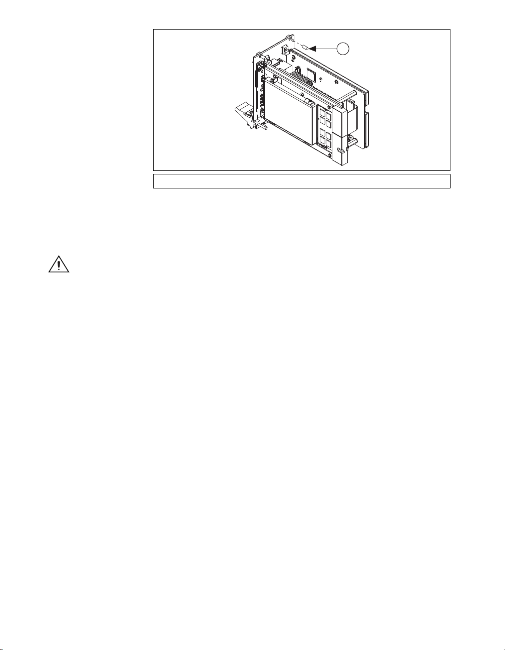
1
1 Protective Screw Cap (4x)
Figure 1. Removing Protective Screw Caps
5. Make sure the injector/ejector handle is in its downward position.
Align the NI PXI-8119 with the card guides on the top and bottom
of the system controller slot.
Caution Do not raise the injector/ejector handle as you insert the NI PXI-8119. The
module will not insert properly unless the handle is in its downward position so that it does
not interfere with the injector rail on the chassis.
6. Hold the handle as you slowly slide the module into the chassis until
the handle catches on the injector/ejector rail.
7. Raise the injector/ejector handle until the module firmly seats into the
backplane receptacle connectors. The front panel of the NI PXI-8119
should be even with the front panel of the chassis.
8. Tighten the four bracket-retaining screws on the top and bottom of the
front panel to secure the NI PXI-8119 to the chassis.
9. Check the installation.
10. Connect the keyboard and mouse to the appropriate connectors. If you
are using a PS/2 keyboard and a PS/2 mouse, a Y-splitter adapter is
available to connect both to a single USB connector. National
Instruments offers a Y-splitter adapter cable, part number 778713-02,
available through the online catalog at
ni.com/products.
11. Connect the DisplayPort monitor video cable to the DisplayPort
connector, or use the DisplayPort-to-VGA adapter included with your
controller to connect a VGA monitor to the DisplayPort connector.
12. Connect peripherals to ports as required by your system configuration.
13. Power on the display. Refer to the NI PXI-8119 User Manual for
details.
14. Power on the chassis.
15. Verify that the controller boots. If it does not boot, refer to the What If
the NI PXI-8119 Does Not Boot? section later in this guide.
NI PXI-8119 Installation Guide 2 ni.com
Page 3

Figure 2 shows a NI PXI-8119 controller installed in the system controller
NI PXIe-1082
1
3
2
slot of a NI PXI-1042 chassis.
1 NI PXI-1042 Chassis
2 NI PXI-8119 Controller
Figure 2. NI PXI-8119 Installed in a PXI Chassis
3 Injector/Ejector Rail
How to Remove the Controller from the PXI Chassis
The NI PXI-8119 controller is designed for easy handling. To remove the
unit from the PXI chassis:
1. Power off the chassis.
2. Remove any cables that may be attached to the controller front panel.
3. Unscrew the 4 bracket-retaining screws in the front panel.
4. Press the injector/ejector handle down.
5. Slide the unit out of the chassis.
What If the NI PXI-8119 Does Not Boot?
Several problems can cause a controller not to boot. Here are some things
to look for and possible solutions.
Things to Notice
• Which LEDs come on? The Power OK LED should stay lit. The
Drive LED should blink during boot as the disk is accessed.
• What appears on the display? Does it hang at some particular point
(BIOS, Operating System, etc.)? If nothing appears on the screen, try
a different monitor. Does your monitor work with a different PC? If it
hangs, note the last screen output that you saw for reference when
consulting National Instruments technical support.
© National Instruments 3 NI PXI-8119 Installation Guide
Page 4

Things to Try
• What has changed about the system? Did you recently move the
system? Was there electrical storm activity? Did you recently add a
new module, memory chip, or piece of software?
• Make sure the chassis is plugged in to a working power source.
• Check any fuses or circuit breakers in the chassis or other power
supply (possibly an uninterruptible power supply).
• Make sure the controller module is firmly seated in the chassis.
• Remove all other modules from the chassis.
• Remove any nonessential cables or devices.
• Try the controller in a different chassis or a similar controller in this
same chassis.
• Clear the CMOS. (Refer to the System CMOS section of the
NI PXI-8119 User Manual.)
• Recover the hard drive on the controller. (Refer to the Hard Drive
Recovery section of the NI PXI-8119 User Manual.)
For more troubleshooting information, refer to the NI PXI-8119 User
Manual. The manual is in PDF format on the documentation CD included
with your controller and on the National Instruments Web site,
ni.com.
What If I Can’t See the Video?
This problem usually results from having the video card output set past the
limits of the monitor. You will need to boot Windows in Safe Mode. To do
this, reboot the controller. As Windows begins to boot, hold down <F8>.
You should now be able to reset the video driver to lower settings. Try
setting the resolution to 640 × 480 and the refresh rate to 60 Hz. Once you
reboot, you can raise these values again, using the test option in Windows.
These settings are accessible through the Advanced tab of the Display item
in the Control Panel. Alternately, you can try a different monitor,
preferably a newer and larger one.
If the system has been booted to Windows without a monitor attached, the
driver may have defaulted to the video output connector being disabled.
Press <Ctrl-Alt-F1> to re-enable the video display in Windows. Press
<Ctrl-Alt-F4> to re-enable a video display. For more information, refer to
KnowledgeBase 3OHCFRD8 at
LabVIEW, National Instruments, NI, ni.com, the National Instruments corporate logo, and the Eagle
logo are trademarks of National Instruments Corporation. Refer to the Trademark Information at
ni.com/trademarks for other National Instruments trademarks. Other product and company
names mentioned herein are trademarks or trade names of their respective companies. For patents
covering National Instruments products/technology, refer to the appropriate location: Help»Patents
in your software, the patents.txt file on your media, or the National Instruments Patent Notice
at ni.com/patents. Refer to the Export Compliance Information at ni.com/legal/
export-compliance for the National Instruments global trade compliance policy and how to
obtain relevant HTS codes, ECCNs, and other import/export data.
© 2012 National Instruments Corporation. All rights reserved.
ni.com/support.
373722A-01 Jul12
 Loading...