

Page 1

GETTING STARTED GUIDE
NI PXI-5695
8 GHz RF Attenuator
Note Before you begin, install and configure your chassis and controller.
This document explains how to install, configure, and test the NI PXI-5695 (NI 5695). The
NI 5695 is an RF attenuator that provides fixed attenuation and programmable attenuation in a
single-slot PXI module. The NI 5695 signal conditioning device ships with the NI-5690
instrument driver, which you can use to program the device.
To access NI 5695 documentation, navigate to Start»All Programs»National Instruments»
NI-5690»Documentation.
Contents
Electromagnetic Compatibility Guidelines...............................................................................2
Unpacking the Kit.....................................................................................................................2
Preparing the Environment....................................................................................................... 3
Verifying the System Requirements......................................................................................... 3
Verifying the Kit Contents........................................................................................................ 3
Other Equipment...............................................................................................................4
Installing the Software.............................................................................................................. 4
Installing the NI 5695............................................................................................................... 4
Connecting Signals................................................................................................................... 6
Direct Connections to the NI 5695................................................................................... 6
Torquing SMA Connections.............................................................................................6
Hardware Front Panel Connectors and Indicators............................................................ 8
Configuring the NI 5695 in MAX............................................................................................ 9
Programming the Device........................................................................................................ 10
NI-5690 Instrument Driver Examples............................................................................ 10
Making Your First Measurement.................................................................................... 10
Troubleshooting...................................................................................................................... 11
NI 5695 Does Not Appear in MAX................................................................................ 11
Module Fails the Self-Test..............................................................................................11
Why Is the ACCESS LED Off When the Chassis is On?...............................................11
Device Is Too Hot...........................................................................................................12
Performance Issues Using an MXI Connection..............................................................12
Where to Go Next................................................................................................................... 13
Worldwide Support and Services............................................................................................ 13
Page 2
Electromagnetic Compatibility Guidelines
This product was tested and complies with the regulatory requirements and limits for
electromagnetic compatibility (EMC) stated in the product specifications. These requirements
and limits provide reasonable protection against harmful interference when the product is
operated in the intended operational electromagnetic environment.
This product is intended for use in industrial locations. However, harmful interference may
occur in some installations, when the product is connected to a peripheral device or test object,
or if the product is used in residential or commercial areas. To minimize interference with
radio and television reception and prevent unacceptable performance degradation, install and
use this product in strict accordance with the instructions in the product documentation.
Furthermore, any changes or modifications to the product not expressly approved by National
Instruments could void your authority to operate it under your local regulatory rules.
Caution To ensure the specified EMC performance, operate this product only with
shielded cables and accessories.
Caution To ensure the specified EMC performance, the length of all I/O cables
except for that connected to the GPS antenna input must be no longer than
3 m (10 ft).
Unpacking the Kit
Caution To prevent electrostatic discharge from damaging the device, ground
yourself using a grounding strap or by holding a grounded object, such as your
computer chassis.
1. Touch the antistatic package to a metal part of the computer chassis.
2. Remove the device from the package and inspect the device for loose components or any
other sign of damage.
Caution Never touch the exposed pins of connectors.
Notify NI if the device appears damaged in any way. Do not install a damaged device.
3. Unpack any other items and documentation from the kit.
Store the device in the antistatic package when the device is not in use.
| ni.com | NI PXI-5695 Getting Started Guide
2
Page 3
Preparing the Environment
1 3 4
2
Ensure that the environment you are using the NI 5695 in meets the following specifications.
............................................................................Operating temperature 0 to 55 °C
............................................................................Operating humidity 10% to 90% RH, noncondensing
............................................................................Pollution Degree 2
............................................................................Maximum altitude 2,000 m
Indoor use only.
Note Refer to the device specifications on ni.com/manuals for complete
specifications.
Note Do not operate the device in a manner not specified in this document.
Product misuse can result in a hazard. You can compromise the safety protection
built into the product if the product is damaged in any way. If the product is
damaged, return it to National Instruments for repair.
Verifying the System Requirements
To use the NI-5690 instrument driver, your system must meet certain requirements.
For more information about minimum system requirements, recommended system, and
supported application development environments (ADEs), refer to the product readme, which
is available on the driver software media or online at ni.com/updates.
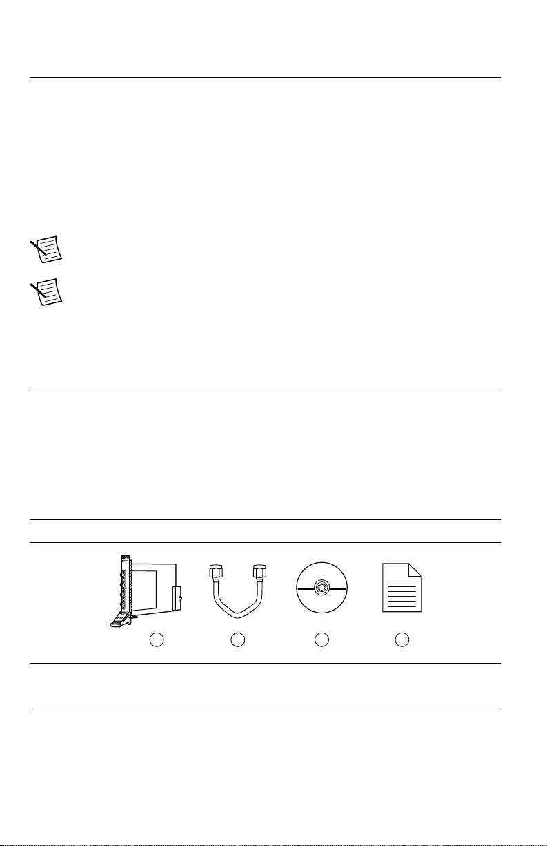
Verifying the Kit Contents
Figure 1. NI 5695 Kit Contents
1. NI 5690 Module
2. SMA Cable
NI PXI-5695 Getting Started Guide | © National Instruments | 3
3. NI-5690 Driver Software Media
4. NI PXI-5695 Getting Started Guide (this
document)
Page 4
Other Equipment
There are several required items not included in your device kit that you need to install or
operate the NI 5695.
Required Items
• A PXI chassis and chassis documentation. The NI PXI-1045 chassis is one available
option for your device. For more information about compatible chassis options, refer to
ni.com.
• A PXI embedded controller or MXI controller system that meets the system requirements
specified in this guide and chassis documentation.
Optional Items
• A 1 N · m standard SMA torque wrench (NI part number 780487-01).
Installing the Software
You must be an Administrator to install NI software on your computer.
1. Install an ADE, such as LabVIEW or LabWindows™/CVI™.
2. Insert the driver software media into your computer. The installer should open
automatically.
If the installation window does not appear, navigate to the drive, double-click it, and
double-click autorun.exe.
3. Follow the instructions in the installation prompts.
Note Windows users may see access and security messages during
installation. Accept the prompts to complete the installation.
4. When the installer completes, select Restart in the dialog box that prompts you to restart,
shut down, or restart later.
Installing the NI 5695
Caution To prevent damage to the device caused by ESD or contamination, handle
the device using the edges or the metal bracket.
Note Ground yourself with a resistor-isolated wrist strap before installing the
module, before touching the center pin of any connector, and before removing or
adjusting any connections to the module.
1. Ensure the AC power source is connected to the chassis before installing the modules.
The AC power cord grounds the chassis and protects it from electrical damage while you
install the modules.
2. Power off the chassis.
| ni.com | NI PXI-5695 Getting Started Guide
4
Page 5
3. Inspect the slot pins on the chassis backplane for any bends or damage prior to
NI PXIe-1062Q
1
2 3
4
5
2
3
NI PXIe-1075
1
installation. Do not install a module if the backplane is damaged.
4. Remove the black plastic connectors from all the captive screws on the module front
panel.
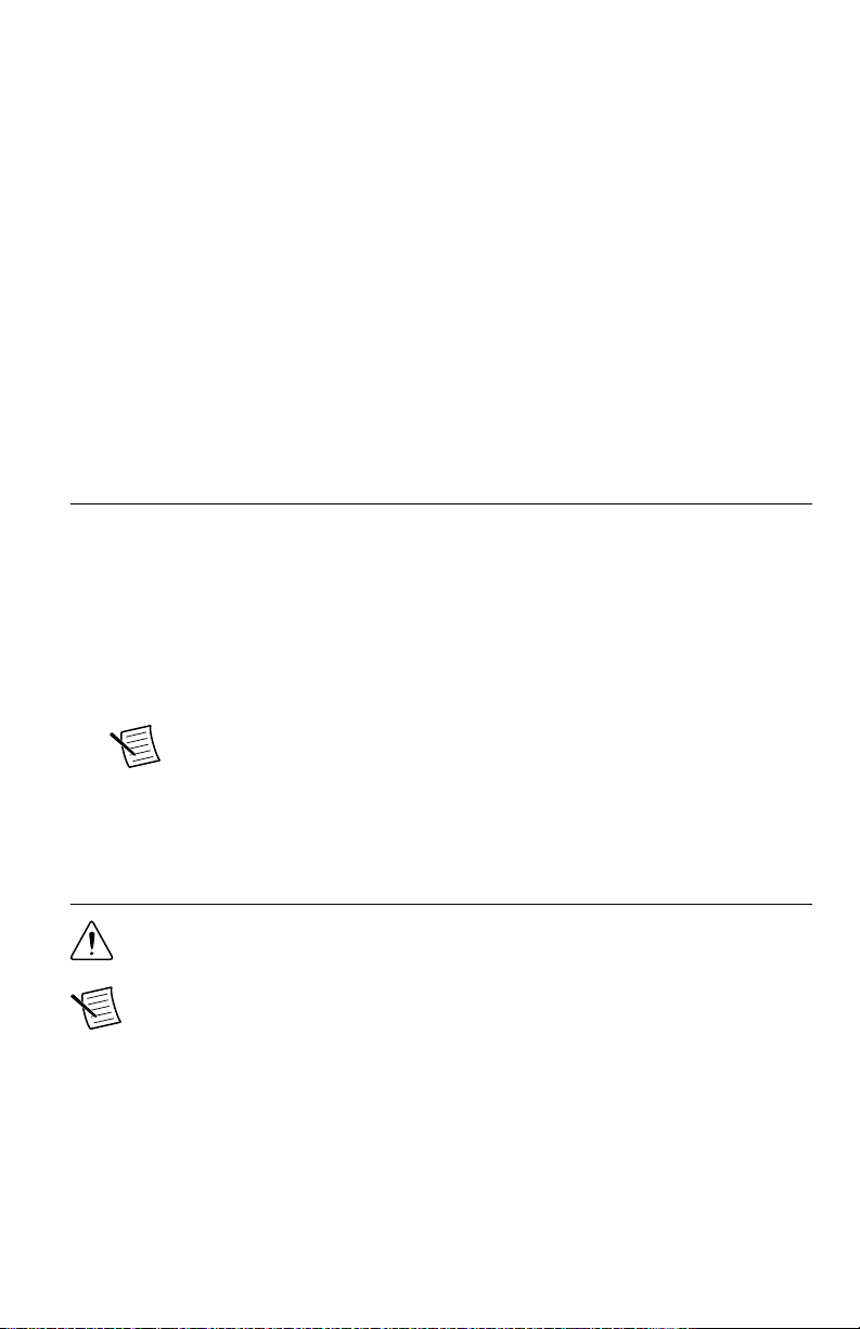
5. Identify a supported slot in the chassis. The following figure shows the symbols that
indicate the slot types.
Figure 2. Chassis Compatibility Symbols
1. PXI Express System Controller Slot
2. PXI Peripheral Slot
3. PXI Express Hybrid Peripheral Slot
4. PXI Express System Timing Slot
5. PXI Express Peripheral Slot
NI 5695 modules can be placed only in PXI peripheral slots.
6. Touch any metal part of the chassis to discharge static electricity.
7. Ensure that the ejector handle is in the unlatched (downward) position.
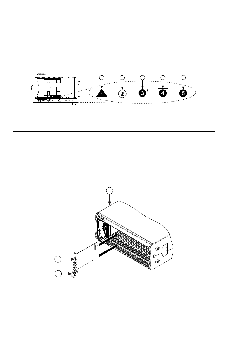
8. Place the module edges into the module guides at the top and bottom of the chassis. Slide
the device into the slot until it is fully inserted.
Figure 3. Module Installation
1. Chassis
2. Hardware Module
3. Ejector Handle in Down (Unlatched Position)
9. Latch the module in place by pulling up on the ejector handle.
10. Secure the device front panel to the chassis using the front-panel mounting screws.
NI PXI-5695 Getting Started Guide
| © National Instruments | 5
Page 6

11. Cover all empty slots using filler panels or slot blockers to maximize cooling air flow.
12. Power on the chassis.
Connecting Signals
Direct Connections to the NI 5695
The NI 5695 is a precision RF instrument that is sensitive to ESD and transients. Ensure you
are making proper direct connections to the NI 5695 to avoid damaging the device.
Caution Apply external signals only while the NI 5695 is powered on. Applying
external signals while the device is powered off may cause damage.
To prevent possible damage to the device, use caution when connecting signal sources and RF
antennas directly to the IN connectors of the NI 5695. Operators, technicians, and all other
users should ensure they are properly grounded when manipulating cables or antennas
connected to the NI 5695 IN connectors.
If you are using noninsulated devices, such as a noninsulated RF antenna, ensure the devices
are maintained in a static-free environment. If you are using an active device, such as a
preamplifier or switch routed to the NI 5695 IN connectors, ensure that there are no signal
transients greater than the RF and DC specifications for the device that are being generated
and sourced to the NI 5695 IN connectors.
Torquing SMA Connections
Note A coaxial cable with open ends can function as a capacitor. Before
connecting any open-ended cable to the NI 5695, momentarily short the center and
outer connectors of the cable together.
Note For best results when connecting signals to the NI 5695 front panel SMA
connectors, use shielded low-loss coaxial cables.
Torque all connections to 100 N ⋅ cm using a standard SMA torque wrench. Apply force
until the wrench clicks.
| ni.com | NI PXI-5695 Getting Started Guide
6
Page 7

Figure 4. Using the Standard SMA Torque Wrench
2
1
ACCESS
ACTIVE
CH 0
IN
+33 dBm
MAX
50
Ω
IN
+27 dBm
MAX
50
Ω
CH 1
50 MHz - 8 GHz
OUT
50
Ω
+33 dBm
MAX
Power
Reverse
OUT
50
Ω
+26 dBm
MAX
Power
Reverse
1. 100 N ⋅ cm SMA Torque Wrench
2. Apply Force Here Until Wrench Clicks
NI PXI-5695 Getting Started Guide | © National Instruments | 7
Page 8

Hardware Front Panel Connectors and Indicators
ACCESS
ACTIVE
CH 0
IN
+33 dBm
MAX
IN
+27 dBm
MAX
CH 1
50 MHz - 8 GHz
OUT
+33 dBm
MAX
Power
Reverse
OUT
+26 dBm
MAX
Power
Reverse
50
Ω
50
Ω
50
Ω
50
Ω
Connector Access Function
CH 0 IN Input CH 0 IN and CH 0 OUT each function as a fixed attenuator with
CH 0 OUT Output
Table 1. NI 5695 Front Panel Connectors
switchable main and direct paths. The main path offers fixed
attenuation with high input power capability. The direct path bypasses
the programmable circuitry and routes the signal directly to the
output. The direct path passes DC level to output, and the main path is
DC-coupled.
8 | ni.com | NI PXI-5695 Getting Started Guide
Page 9

Table 1. NI 5695 Front Panel Connectors (Continued)
Connector Access Function
CH 1 IN Input CH 1 IN and CH 1 OUT each function as a programmable attenuator.
CH 1 OUT Output
LED Indications
These channels offer attenuation that is adjustable in 0.5 dB nominal
steps.1 CH 1 IN and CH 1 OUT are AC-coupled.
Table 2. NI 5695 Front Panel LED Indicators
ACCESS Indicates the basic hardware status of the NI RF signal conditioning module.
OFF—The module is not yet functional, or has detected a problem with a PXI
power rail.
AMBER—The module is being accessed.
GREEN—The module is ready to be programmed.
ACTIVE Indicates the operational status of the NI RF signal conditioning module.
OFF—The module is in an uninitialized state.
GREEN—The module is in a ready state or in use.
Related Information
Refer to the Devices book in the NI RF Signal Conditioning Devices Help for more
information about using channels and paths.
Configuring the NI 5695 in MAX
Use Measurement & Automation Explorer (MAX) to configure your National Instruments
hardware. MAX informs other programs about which devices reside in the system and how
they are configured. MAX is automatically installed with the NI-5690 instrument driver.
1. Launch Measurement & Automation Explorer (MAX).
MAX should automatically detect the device you installed.
2. In the Configuration pane, double-click Devices and Interfaces to see the list of installed
devices. Installed devices appear under the name of their associated chassis.
Note If you are using the NI 5695 with the LabVIEW Real-Time Module,
expand Remote Systems. Find your target IP address or name, expand it, and
then expand Devices and Interfaces.
1
Refer to the NI PXI-5695 Specifications for detailed attenuation specifications.
NI PXI-5695 Getting Started Guide | © National Instruments | 9
Page 10

3. Expand your Chassis tree item. MAX lists all devices installed in the chassis. Your
default device names may vary.
Note If you do not see your hardware listed, press <F5> to refresh the list of
installed devices. If the device is still not listed, power off the system, ensure
the device is correctly installed, and restart.
4. Record the device identifier MAX assigns to the hardware. Use this identifier when
programming the NI 5695.
5. The MAX self-test performs a basic verification of hardware resources. To self-test a
module in MAX, right click the module and select Self-Test.
Programming the Device
You can use the NI-5690 instrument driver to program the NI 5695 in the supported ADE of
your choice.
NI-5690 Instrument Driver Examples
Examples demonstrate the functionality of the device and serve as programming models and
building blocks for your own applications. The NI Example Finder is a utility available for
some ADEs that organizes examples into categories and allows you to easily browse and
search installed examples. You can see descriptions and compatible hardware models for each
example, or see all the examples compatible with one particular hardware model.
To locate examples, refer to the following table.
Table 3. Locating NI-5690 Examples
Application Development
Environment (ADE)
Locating Examples
LabVIEW or
LabWindows/CVI
LabVIEW, LabWindows/
CVI, or C
Locate examples with the NI Example Finder. Within
LabVIEW or LabWindows/CVI, select Help»Find
Examples, and navigate to Hardware Input and Output»
Modular Instruments»NI-5690 (RF Preamplifier).
Locate examples2 from the Start menu by navigating to
Start»All Programs»National Instruments»NI-5690»
Examples.
Making Your First Measurement
To begin making measurements with the NI 5695, complete the following steps:
1. Launch your ADE.
2. Navigate to Start»All Programs»National Instruments»NI-5690»Examples and open
one of the examples.
2
You can modify an NI-5690 C example to create an application with Microsoft Visual C/C++, and
all required include and library files are automatically added to the project.
10 | ni.com | NI PXI-5695 Getting Started Guide
Page 11

3. Select your device from the resource name control.
4. Run the example.
Troubleshooting
If an issue persists after you complete a troubleshooting procedure, contact NI technical
support or visit ni.com/support.
NI 5695 Does Not Appear in MAX
1. In the MAX Configuration pane, click Devices and Interfaces.
2. Expand the Chassis tree to see the list of installed devices, and press <F5> to refresh the
list.
3. If the module is still not listed, power off the system, ensure that all hardware is correctly
installed, and restart the system.
4. Navigate to the Device Manager.
Option Description
Windows 8 Right-click the Start screen, and select All apps»Control Panel»
Hardware and Sound»Device Manager.
Windows 7 Select Start»Control Panel»Device Manager.
Windows Vista Select Start»Control Panel»System and Maintenance»Device
Manager.
Windows XP Select Start»Control Panel»System»Hardware»Device Manager.
5. If you are using a PXI controller, verify that a National Instruments entry appears in the
system device list. Reinstall the NI-5690 instrument driver and the device if error
conditions appear in the list. If you are using a MXI controller, right-click PCI-to-PCI
Bridge, and select Properties from the shortcut menu to verify that the bridge is enabled.
Module Fails the Self-Test
1. Restart the system.
2. Launch MAX, and perform the self-test again.
3. Power off the PXI chassis.
4. Reinstall the failed module in a different PXI slot.
5. Power on the PXI chassis.
6. Perform the self-test again.
Why Is the ACCESS LED Off When the Chassis is On?
The LEDs may not illuminate until the device has been configured in MAX. Before
proceeding, verify that the NI 5695 appears in MAX.
NI PXI-5695 Getting Started Guide
| © National Instruments | 11
Page 12

If the ACCESS LED fails to illuminate after you power on the chassis, a problem may exist
with the chassis power rails, a hardware module, or the LED.
Caution Apply external signals only while the NI 5695 is powered on. Applying
external signals while the device is powered off may cause damage.
1. Disconnect any signals from the module front panels.
2. Power off the chassis.
3. Remove the module from the chassis and inspect it for damage. Do not reinstall a
damaged device.
4. Install the module in a different chassis slot from which you removed it.
5. Power on the chassis.
6. Verify that the device appears in MAX.
7. Reset the device in MAX and perform a self-test.
Device Is Too Hot
NI 5695 devices have onboard sensors that monitor the device operating temperature. When
running at room temperature (25 °C), the sensor typically reads a temperature of 30 °C ± 5 °C,
depending on the module and what other devices are installed in the chassis.
Access the onboard sensor using the ni5690 Get Temperature VI or the
ni5690_getTemperature function.
Performance Issues Using an MXI Connection
When you use an MXI-3 connection to control the PXI chassis, you must run the MXI
Optimization Application prior to using the NI 5695. By default, this application runs
automatically when Windows starts. Using an MXI connection without running this
application may result in a time exceeded or internal software error, an
initialization timeout, or a performance issue when using the NI 5695.
1. Ensure the MXI software is installed. If the MXI software is not installed, refer to the
setup instructions included with the MXI kit.
After installation, you may be required to restart your computer before using the MXI
application.
2. For MXI-3 optimization, select Start»All Programs»National Instruments MXI-3»
MXI-3 Optimization.
MXI-4 optimization is performed automatically by the MXI-4 hardware.
If you continue to have initialization or performance issues, refer to the MXI documentation
included in your MXI kit, contact NI technical support, or visit ni.com/support.
| ni.com | NI PXI-5695 Getting Started Guide
12
Page 13

Where to Go Next
custom applications within
an application programming
interface (API).
NI-5690 Examples*
NI RF Signal Conditioning
Devices Help*
NI-5690 Instrument Driver
about hardware features
or review device
specifications.
more about your products through ni.com.
NI PXI-5695
Specifications*
NI RF Signal Conditioning
Devices Help*
the application
development environment (ADE)
for your application.
Learn LabVIEW Basics
Getting Started with
LabWindows/CVI
*This item is also installed with the driver software.
Located in the hardware kit Located online at ni.com/manuals Located using the NI Example Finder
EXPLORE LEARN CREATE
DISCOVER
Support
ni.com/support
RF Solutions
ni.com/rf
Updates
ni.com/updates
Services
ni.com/services
RF Preamplifier
NI PXI-5690
Refer to the following figure for information about other product tasks and associated
resources for those tasks.
Tip The NI RF Signal Conditioning Devices Help is an HTML version of a
traditional user manual that includes detailed information about RF fundamentals,
device features, and programming with the NI-5690 instrument driver.
Worldwide Support and Services
The National Instruments website is your complete resource for technical support. At ni.com/
support, you have access to everything from troubleshooting and application development
self-help resources to email and phone assistance from NI Application Engineers.
Visit ni.com/services for NI Factory Installation Services, repairs, extended warranty, and
other services.
NI PXI-5695 Getting Started Guide
| © National Instruments | 13
Page 14

Visit ni.com/register to register your National Instruments product. Product registration
facilitates technical support and ensures that you receive important information updates from
NI.
A Declaration of Conformity (DoC) is our claim of compliance with the Council of the
European Communities using the manufacturer’s declaration of conformity. This system
affords the user protection for electromagnetic compatibility (EMC) and product safety. You
can obtain the DoC for your product by visiting ni.com/certification. If your product supports
calibration, you can obtain the calibration certificate for your product at ni.com/calibration.
National Instruments corporate headquarters is located at 11500 North Mopac Expressway,
Austin, Texas, 78759-3504. National Instruments also has offices located around the world.
For telephone support in the United States, create your service request at ni.com/support or
dial 1 866 ASK MYNI (275 6964). For telephone support outside the United States, visit the
Worldwide Offices section of ni.com/niglobal to access the branch office websites, which
provide up-to-date contact information, support phone numbers, email addresses, and current
events.
Refer to the NI Trademarks and Logo Guidelines at ni.com/trademarks for information on National Instruments
trademarks. Other product and company names mentioned herein are trademarks or trade names of their respective
companies. For patents covering National Instruments products/technology, refer to the appropriate location: Help»
Patents in your software, the patents.txt file on your media, or the National Instruments Patent Notice at ni.com/
patents. You can find information about end-user license agreements (EULAs) and third-party legal notices in the
readme file for your NI product. Refer to the Export Compliance Information at ni.com/legal/export-compliance for
the National Instruments global trade compliance policy and how to obtain relevant HTS codes, ECCNs, and other
import/export data. NI MAKES NO EXPRESS OR IMPLIED WARRANTIES AS TO THE ACCURACY OF THE
INFORMATION CONTAINED HEREIN AND SHALL NOT BE LIABLE FOR ANY ERRORS. U.S. Government
Customers: The data contained in this manual was developed at private expense and is subject to the applicable limited
rights and restricted data rights as set forth in FAR 52.227-14, DFAR 252.227-7014, and DFAR 252.227-7015.
© 2014 National Instruments. All rights reserved.
376268A-01 Jul14
 Loading...