

Page 1
GETTING STARTED GUIDE
NI PXI-5671
2.7 GHz RF Vector Signal Generator
Note Before you begin, install and configure your chassis and controller.
This document explains how to install, configure, and test the NI PXI-5671 (NI 5671). The
NI 5671 is a 2.7 GHz RF vector signal generator (VSG) with digital upconversion. The
NI 5671 ships with the NI-RFSG instrument driver, which you use to program the device.
The NI 5671 comprises the following devices:
• NI PXI-5610 (NI 5610) RF upconverter module
• NI PXI-5441 (NI 5441) arbitrary waveform generator (AWG) module
To access NI 5671 documentation, navigate to Start»All Programs»National Instruments»
NI-RFSG»Documentation.
The specifications document for your device is installed with the driver software. Refer to
ni.com/manuals for the most recent specifications for your device.
Caution The protection provided by this product may be impaired if it is used in a
manner not described in this document.
Hot Surface If the NI 5671 has been in use, it may exceed safe handling
temperatures and cause burns. Allow the NI 5671 to cool before removing it from
the chassis.
Contents
Electromagnetic Compatibility Guidelines...............................................................................2
Verifying the System Requirements..........................................................................................2
Unpacking the Kit..................................................................................................................... 2
Verifying the Kit Contents................................................................................................ 4
Preparing the Environment....................................................................................................... 5
Installing the Software.............................................................................................................. 6
Installing the NI 5671............................................................................................................... 6
Interconnecting the NI 5671 Modules.............................................................................. 8
Configuring the NI 5671 in MAX...........................................................................................15
Page 2
Programming the NI 5671.......................................................................................................16
NI-RFSG Examples........................................................................................................ 16
Generating a Signal Using the NI-RFSG Soft Front Panel.............................................17
Building a Basic NI-RFSG Application..........................................................................17
Troubleshooting...................................................................................................................... 21
Why Is the ACCESS LED Off When the Chassis is On?...............................................21
What Should I Do if the NI 5671 Doesn't Appear in MAX?..........................................21
What Should I Do if the Module Fails the Self-Test?.....................................................22
What Should I Do if the Thermal Shutdown Error Appears?.........................................22
What Should I Do if I Experience Performance Issues Using an MXI Connection?..... 22
Where to Go Next................................................................................................................... 23
Worldwide Support and Services............................................................................................ 23
Electromagnetic Compatibility Guidelines
This product was tested and complies with the regulatory requirements and limits for
electromagnetic compatibility (EMC) stated in the product specifications. These requirements
and limits are designed to provide reasonable protection against harmful interference when the
product is operated in the intended operational electromagnetic environment.
This product is intended for use in industrial locations. However, harmful interference may
occur in some installations, when the product is connected to a peripheral device or test object,
or if the product is used in residential or commercial areas. To minimize interference with
radio and television reception and prevent unacceptable performance degradation, install and
use this product in strict accordance with the instructions in the product documentation.
Furthermore, any modifications to the product not expressly approved by National Instruments
could void your authority to operate it under your local regulatory rules.
Caution To ensure the specified EMC performance, operate this product only with
shielded cables and accessories.
Caution To ensure the specified EMC performance, the length of all I/O cables
must be no longer than 3 m (10 ft).
Verifying the System Requirements
To use the NI-RFSG instrument driver, your system must meet certain requirements.
For more information about minimum system requirements, recommended system, and
supported application development environments (ADEs), refer to the product readme, which
is available on the driver software media or online at ni.com/updates.
Unpacking the Kit
Caution To prevent electrostatic discharge (ESD) from damaging the device,
ground yourself using a grounding strap or by holding a grounded object, such as
your computer chassis.
2 | ni.com | NI PXI-5671 Getting Started Guide
Page 3

1. Touch the antistatic package to a metal part of the computer chassis.
2. Remove the device from the package and inspect the device for loose components or any
other sign of damage.
Caution Never touch the exposed pins of connectors.
Notify NI if the device appears damaged in any way. Do not install a damaged device.
3. Unpack any other items and documentation from the kit.
Store the device in the antistatic package when the device is not in use.
NI PXI-5671 Getting Started Guide | © National Instruments | 3
Page 4
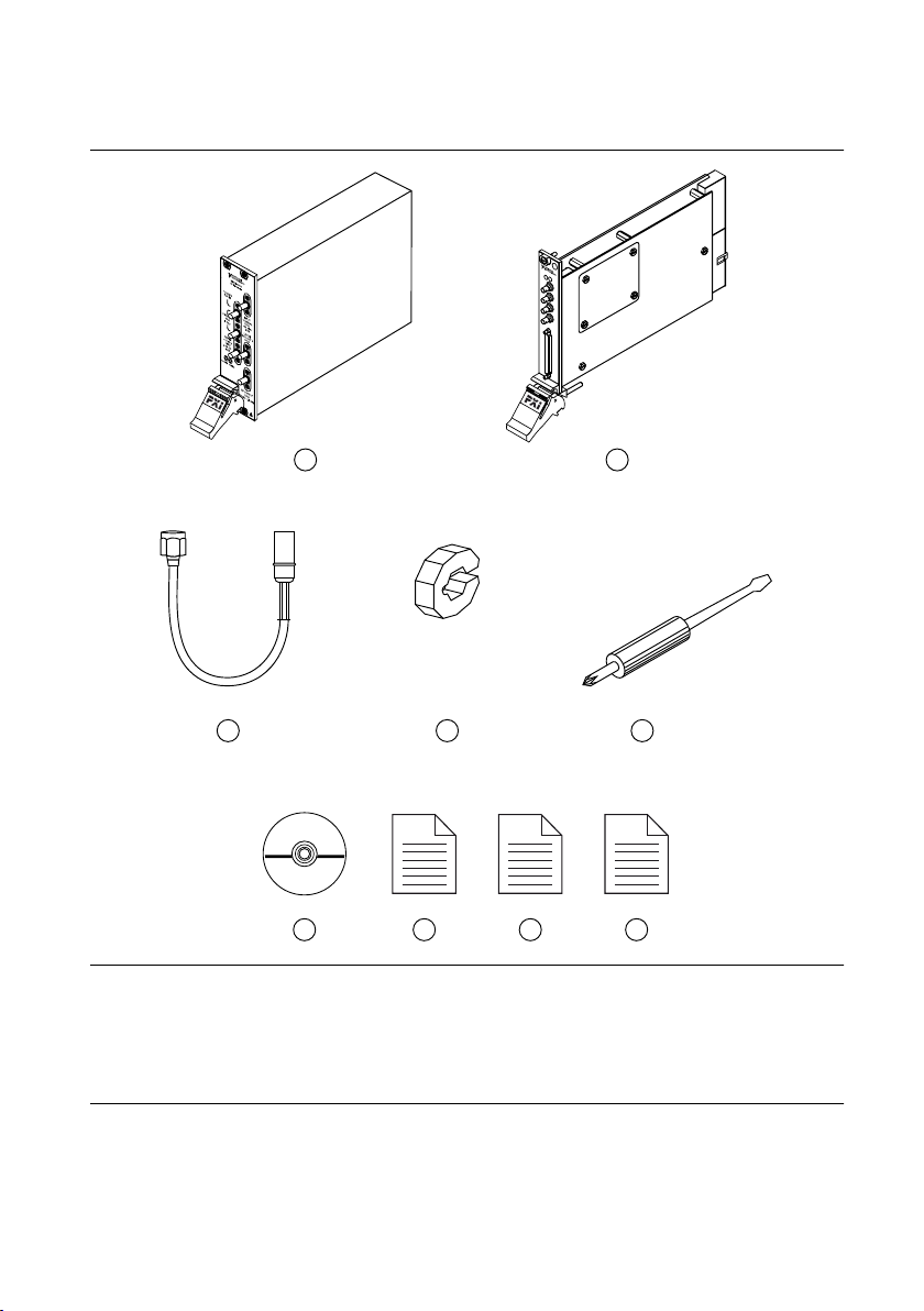
Verifying the Kit Contents
5
1
3
2
4
NI PXI-5421
6 7 8 9
Figure 1. NI 5671 Kit Contents
1. NI PXI-5610 RF Upconverter Module
2. NI PXI-5441 AWG Module
3. Two Semi-Flexible SMA (m)-to-SMB Cables, Part
Number 190846B-01
4. Two Cable Wrenches, Part Number 746016-01
5. Screwdriver, Part Number 772006-01
4 | ni.com | NI PXI-5671 Getting Started Guide
6. Driver Software DVD
7. NI PXI-5671 Getting Started Guide (this
document)
8. Read Me First: Safety and Electromagnetic
Compatibility
9. Maintain Forced-Air Cooling Note to Users
Page 5

Other Equipment
There are several required items not included in your device kit that you need to install or
operate the NI 5671.
Required Items
• A PXI chassis and chassis documentation. The NI PXIe-1085 chassis is one available
option for your device. For more information about compatible chassis options, refer to
ni.com.
• A PXI embedded controller or MXI controller system that meets the system requirements
specified in this guide and chassis documentation.
Optional Items
• A 1 N · m standard SMA torque wrench (NI part number 780487-01).
Preparing the Environment
Ensure that the environment you are using the NI 5671 in meets the following specifications.
Operating ambient temperature
....................................................................NI PXI-5610 upconverter 0 °C to 55 °C (Tested in accordance with
IEC 60068-2-1 and IEC 60068-2-2. Meets
MIL PRF-28800F Class 3 low temperature
limit and MIL PRF-28800F Class 2 high
temperature limit.)
....................................................................NI PXI-5441 AWG 0° to 45° (When installed in an NI PXI-101X
or NI PXI-1000B chassis.)
............................................................................Operating relative humidity
(IEC-60068-2-56)
............................................................................Maximum altitude 2,000 m (800 mbar) (at 25 °C ambient
............................................................................Pollution Degree 2
10% to 90%, noncondensing
temperature)
Indoor use only.
Caution Clean the hardware with a soft, nonmetallic brush. Make sure that the
hardware is completely dry and free from contaminants before returning it to
service.
Note Refer to the NI PXI-5670/5671 Specifications at ni.com/manuals for
complete specifications.
NI PXI-5671 Getting Started Guide | © National Instruments | 5
Page 6
Installing the Software
You must be an Administrator to install NI software on your computer.
1. Install an ADE, such as LabVIEW or LabWindows™/CVI™.
2. Insert the driver software DVD into your computer. The installer should open
automatically.
If the installation window does not appear, navigate to the drive, double-click it, and
double-click autorun.exe.
3. Follow the instructions in the installation prompts to install the NI-RFSG driver software.
Note Windows users may see access and security messages during
installation. Accept the prompts to complete the installation.
4. When the installer completes, restart your system.
Installing the NI 5671
Caution To prevent damage to the device caused by ESD or contamination, handle
the device using the edges or the metal bracket.
You must install NI-RFSG before installing the hardware.
Before you install the hardware, refer to the guidelines in the Maintain Forced-Air Cooling
Note to Users included with the module to ensure that the chassis can cool the device
effectively.
To use the included cables, you must install the NI 5441 AWG module in the slot immediately
to the right of the NI 5610 RF upconverter module.
1. Ensure the AC power source is connected to the chassis before installing the modules.
The AC power cord grounds the chassis and protects it from electrical damage while you
install the modules.
2. Power off the chassis.
3. Inspect the slot pins on the chassis backplane for any bends or damage prior to
installation. Do not install a module if the backplane is damaged.
4. Remove the black plastic connectors from all the captive screws on the module front
panel.
5. Identify a supported slot in the chassis. The following figure shows the symbols that
indicate the slot types.
6 | ni.com | NI PXI-5671 Getting Started Guide
Page 7
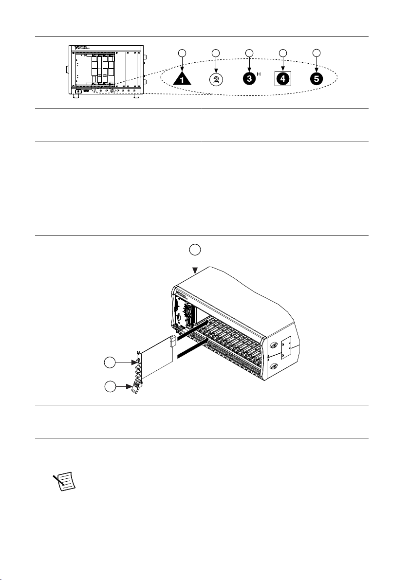
Figure 2. Chassis Compatibility Symbols
NI PXIe-1062Q
1
2 3
4
5
2
3
NI PXIe-1075
1
1. PXI Express System Controller Slot
2. PXI Peripheral Slot
3. PXI Express Hybrid Peripheral Slot
4. PXI Express System Timing Slot
5. PXI Express Peripheral Slot
NI 5671 modules can be placed in PXI peripheral slots or PXI Express Hybrid peripheral
slots.
6. Touch any metal part of the chassis to discharge static electricity.
7. Ensure that the ejector handle is in the unlatched (downward) position.
8. Place the module edges into the module guides at the top and bottom of the chassis. Slide
the device into the slot until it is fully inserted.
Figure 3. Module Installation
1. Chassis
2. Hardware Module
3. Ejector Handle in Down (Unlatched) Position
9. Latch the module in place by pulling up on the ejector handle.
10. Secure the device front panel to the chassis using the front-panel mounting screws.
Note Tightening the top and bottom mounting screws increases mechanical
stability and also electrically connects the front panel to the chassis, which can
improve the signal quality and electromagnetic performance.
11. Cover all empty slots using filler panels or slot blockers to maximize cooling air flow.
NI PXI-5671 Getting Started Guide | © National Instruments | 7
Page 8

12. Power on the chassis.
RF Upconverter
PFI 0
PFI 1
ACCESS ACTIVE
CLK
IN
CH 0
DIGITAL DATA & CONTROL
2
1
Related Information
Installing the Software on page 6
Interconnecting the NI 5671 Modules
Figure 4. NI 5671 Front Panel Interconnection
1. Flexible SMA-to-SMB Cable
2. Flexible SMA-to-SMB Cable
1. Using a flexible SMA-to-SMB cable, connect the INPUT connector on the NI 5610 front
panel to the CH 0 connector on the NI 5441 front panel.
Note Ensure that the SMA cable center pins properly align with the SMA
connectors to avoid bending the cable pins or damaging the front panel
connectors on the device.
8 | ni.com | NI PXI-5671 Getting Started Guide
Page 9

2. Using a flexible SMA-to-SMB cable, connect the TO AWG CLK IN connector on the
NI 5610 front panel to the CLK IN connector on the NI 5441 front panel.
3. Hand-tighten all SMA cable ends on the SMA connectors. The cable connectors should
tighten without much torque or effort.
4. Carefully complete tightening all SMA connectors to 1 N · m using an appropriate torque
wrench or torque screwdriver and SMA driver bit (not included). Tighten only until the
wrench clicks.
Caution Incorrect torque at SMA connections can degrade signal fidelity and
phase-locked loop (PLL) performance and may cause insertion loss. Use an
appropriate torque wrench or torque screwdriver and SMA driver bit to ensure
all SMA connections are properly torqued. SMA connectors for connections to
external equipment may require torque different from 1 N · m, depending on
the connector type, material, and manufacturer.
5. Power on your PXI chassis and controller system.
6. Verify that the ACCESS LED is illuminated on all modules. If an LED is not illuminated,
refer to the Troubleshooting section of this document.
Related Information
Configuring the NI 5671 in MAX on page 15
Direct Connections to the NI 5671
The NI 5671 is a precision RF instrument that is sensitive to ESD and transients. Ensure you
take the following precautions when making direct connections to the NI 5671 to avoid
damaging the device.
Note Do not apply external signals to the NI 5671. Applying external signals may
cause damage.
• Ensure you are properly grounded when manipulating cables or antennas connected to the
NI 5671.
• If you are using noninsulated devices, such as a noninsulated RF antenna, ensure the
devices are maintained in a static-free environment.
• If you are using an active device, such as a preamplifier or switch routed to the NI 5671,
ensure no signal transients are sourced to the NI 5671.
NI PXI-5671 Getting Started Guide | © National Instruments | 9
Page 10

NI 5610 RF Upconverter Module
The NI 5610 RF upconverter module contains six connectors and two multicolor LEDs.
Figure 5. NI 5610 RF Upconverter Module Front Panel
Table 1. Device Front Panel Icon Definition
Refer to the user documentation for required maintenance measures to ensure user
safety and/or preserve the specified EMC performance.
10 | ni.com | NI PXI-5671 Getting Started Guide
Page 11

Table 2. NI 5610 RF Upconverter Module Front Panel Connectors
Connector Use
TO AWG CLK IN Connects to the CLK IN connector on the NI 5441 AWG module
10 MHz OUT
front panel.
Both connectors are output terminals for replications of the
upconverter 10 MHz frequency reference signal, which is useful for
driving other devices. Each replication is 180° out of phase with the
other. The output signal at these connectors is always on and cannot
be disabled.
REF IN Routes an external frequency reference signal that can be propagated
to the PXI backplane. The NI 5610 can lock to this signal.
INPUT Connects to the CH 0 output on the NI 5441 AWG module front
panel.
Routes the IF signal from the NI 5441 AWG module for frequency
translation.
LOCAL OSC OUT 0 Routes the auxiliary local oscillator signal.
RF OUTPUT Routes the upconverted signal at the requested RF frequency.
NI PXI-5671 Getting Started Guide | © National Instruments | 11
Page 12

Table 3. NI 5610 RF Upconverter Module Front Panel LEDs
LED Indications
ACCESS Indicates the basic hardware status of the module.
OFF—The module is not yet functional, or the module has detected a problem
with a PXI power rail.
AMBER—The module is being accessed. Accessed means that the device setup
registers are being written to in order to control the device.
GREEN—The module is ready to be programmed by NI-RFSG.
ACTIVE Indicates the status of the module PLLs.
OFF—The module is in an uninitialized state; there is no error.
AMBER—The module PLLs are attempting to lock.
GREEN—The module is in a ready state; applicable PLLs are locked and the
reverse power protection circuit is closed.
RED—The module has detected an error state; this state may indicate an overload
(reverse power protection circuit is open), a PLL lock failure, or a thermal
shutdown condition.
12 | ni.com | NI PXI-5671 Getting Started Guide
Page 13

NI 5441 AWG Module
PFI 0
PFI 1
NI PXI-5441
ACCESS ACTIVE
CLK
IN
CH 0
DIGITAL DATA & CONTROL
The NI 5441 AWG module front panel contains five connectors and two multicolor LEDs.
Figure 6. NI 5441 AWG Module Front Panel
Table 4. Device Front Panel Icon Definition
Refer to the user documentation for required maintenance measures to ensure user
safety and/or preserve the specified EMC performance.
NI PXI-5671 Getting Started Guide | © National Instruments | 13
Page 14

Table 5. NI 5441 AWG Module Front Panel Connectors
Connector Use
CH 0 Connects to the IF INPUT connector on the NI 5610 front
panel.
This connector is the output terminal for an IF waveform
for upconversion to the desired RF frequency.
CLK IN Connects to the REF OUT connector on the NI 5610 front
panel.
This connector is the input terminal for the NI 5441
Reference Clock signal.
PFI 0 Both connectors accept a trigger from an external source to
PFI 1
start or step through signal generation. Both terminals are
bidirectional SMB connectors.
DIGITAL DATA & CONTROL Routes the 16-bit digital pattern outputs, digital pattern
clock output, trigger outputs, trigger inputs, and a clock
input.
Table 6. NI 5441 AWG Module Front Panel LEDs
LED Indications
ACCESS Indicates the basic hardware status of the module.
OFF—The module is not yet functional or has detected a problem with a power
rail.
AMBER—The module is being accessed. Accessed means that the device setup
registers are being written to in order to control the device or load waveforms.
GREEN—The module is ready to be programmed by NI-RFSG.
ACTIVE Indicates the state of the module.
OFF—The module is not armed or triggered.
AMBER—The module is armed and waiting for a Start Trigger.
GREEN—The module has received a Start Trigger and is generating a waveform.
RED—The module has detected an error state; this state may indicate a PLL lock
failure or a thermal shutdown condition.
14 | ni.com | NI PXI-5671 Getting Started Guide
Page 15

Configuring the NI 5671 in MAX
Use Measurement & Automation Explorer (MAX) to configure your National Instruments
hardware. MAX informs other programs about which devices reside in the system and how
they are configured. MAX is automatically installed with NI-RFSG.
1. Launch MAX.
2. In the configuration tree, double-click Devices and Interfaces to see the list of installed
devices.
Note If you are using the NI 5671 with the LabVIEW Real-Time Module,
expand Remote Systems. Find your target IP address or name, expand it, and
then expand Devices and Interfaces.
Installed devices appear under the name of their associated chassis.
3. Expand your Chassis tree item.
MAX lists all devices installed in the chassis. Your default device names may vary.
Note If you do not see your device listed, press <F5> to refresh the list of
installed devices. If the device is still not listed, power off the system, ensure
the device is correctly installed, and restart.
4. Record the device identifier MAX assigns to the hardware. Use this identifier when
programming the NI 5671.
5. Associate the hardware modules that comprise your device.
a) Select the NI 5610 that is identified as not configured in the configuration tree.
b) In the Associated Devices section, select the appropriate module from each system
component drop-down listbox.
For the NI 5671, you must associate the NI 5610 RF upconverter module with the
NI 5441 AWG module.
c) Click Save in the MAX toolbar.
Note Module associations may be lost when you move the modules to
different chassis slots.
6. Self-test the device modules by selecting the modules in the configuration tree, and
clicking Self-Test in the MAX toolbar. Repeat this step for all modules in your NI 5671
system.
The MAX self-test performs a basic verification of hardware resources.
Related Information
Interconnecting the NI 5671 Modules on page 8
Refer to the NI RF Signal Generators Help for information about renaming devices.
NI PXI-5671 Getting Started Guide | © National Instruments | 15
Page 16

Programming the NI 5671
You can generate signals interactively using the NI-RFSG Soft Front Panel (SFP) or you can
use the NI-RFSG instrument driver to program your device in the supported ADE of your
choice.
Table 7. NI 5671 Programming Options
Application
Programming
Interface (API)
Location Description
NI-RFSG SFP Available from the Start
menu at Start»All
Programs»National
Instruments»NI-RFSG»
NI-RFSG Soft Front
Panel.
NI-RFSG
Instrument Driver
Related Information
Refer to the Getting Started section of the NI RF Signal Generators Help for detailed
instructions about how to generate signals in a specific ADE.
Refer to the Creating an Application with Microsoft Visual C and C++ topic of the NI RF
Signal Generators Help to manually add all required include and library files to your project.
LabVIEW—Available on
the LabVIEW Functions
palette at Measurement
I/O»NI-RFSG.
LabWindows/CVI—
Available at Program
Files»IVI Foundation»
IVI»Drivers»niRFSG.
Microsoft Visual C/C++ Add all required include and library files
NI-RFSG SFP controls, generates, and
presents data similar to stand-alone RF
vector signal generators. NI-RFSG SFP
operates on the PC, so it provides
additional processing, storage, and display
capabilities.
NI-RFSG configures and operates the
device hardware, performs waveform
programming and generation, and
performs basic modulation tasks using
LabVIEW VIs or LabWindows/CVI
functions. After you associate the modules
of the NI 5671 in MAX, NI-RFSG
operates the modules as a single
instrument.
to your project to create an NI-RFSG
application in Microsoft Visual C/C++.
NI-RFSG Examples
Examples demonstrate the functionality of the device and serve as programming models and
building blocks for your own applications. The NI Example Finder is a utility available for
some ADEs that organizes examples into categories and allows you to easily browse and
search installed examples. You can see descriptions and compatible hardware models for each
example or see all the examples compatible with one particular hardware model.
16 | ni.com | NI PXI-5671 Getting Started Guide
Page 17

You can locate LabVIEW or LabWindows/CVI examples with the NI Example Finder. Within
LabVIEW or LabWindows/CVI, select Help»Find Examples and navigate to Hardware
Input and Output»Modular Instruments.
Generating a Signal Using the NI-RFSG Soft Front Panel
To verify your device configuration, use the NI-RFSG Soft Front Panel (SFP) in MAX to
generate a simple signal.
1. Within MAX, select the NI 5610 module in the configuration tree.
2. Select Soft Front Panel from the MAX toolbar.
The NI-RFSG SFP launches.
3. Within the NI-RFSG SFP, specify a frequency and a power level for signal generation.
Caution Clicking RF On/Off generates a signal from the RF OUTPUT
connector of the NI 5610 front panel. Disconnect any equipment that can be
damaged by the test signal prior to clicking the RF On/Off button on the
NI-RFSG SFP.
4. Click
5. Click RF On/Off to stop signal generation.
RF On/Off to begin signal generation.
Note Refer to the Troubleshooting section of this document if an
ACTIVE LED does not turn on or if the NI-RFSG SFP generates an error.
During signal generation, the ACTIVE LED on each of the NI 5671 hardware modules
illuminates.
Building a Basic NI-RFSG Application
You can build a basic NI-RFSG application in LabVIEW for generating continuous sine wave
signals.
Adding the Core NI-RFSG VIs to a Blank VI
Create a new application that includes the core NI-RFSG VIs.
1. Launch LabVIEW.
2. To create a blank VI, select File»New VI.
3. Display the block diagram by selecting Window»Show Block Diagram.
Tip Activate the LabVIEW context help by selecting Help»Show Context
Help.
4. Right-click the VI block diagram to launch the Functions palette.
5. Navigate to the NI-RFSG VIs on the NI-RFSG palette.
Tip You can use the Search button on the Functions palette to find the NI-
RFSG palette.
6. Add the core NI-RFSG VIs from the NI-RFSG palette to the block diagram, and wire the
VIs together as shown in the following figure.
NI PXI-5671 Getting Started Guide | © National Instruments | 17
Page 18

Figure 7. Basic NI-RFSG Block Diagram
7. Right-click the resource name input on the niRFSG Initialize VI, and select Create»
Control to create a front panel control where you specify the
NI RF vector signal generator device name.
Figure 8. Resource Name Input on the niRFSG Initialize VI
8. Right-click the frequency (Hz) input on the niRFSG Configure RF VI, and select Create»
Control.
9. Right-click the power level (dBm) input on the niRFSG Configure RF VI, and select
Create»Control.
10. Display the VI front panel by clicking it or by selecting Window»Show Front Panel.
11. In the VI front panel power level (dBm) control, enter 0. In the frequency (Hz) control,
enter 100M (100 MHz).
12. In the VI front panel resource name control, enter the NI 5610 upconverter device name
that you specified in MAX.
Adding a While Loop
Add a While Loop to continuously generate the signal and check the generation status until
you click the Stop button.
1. Display the VI block diagram, and select the While Loop on the Structures palette.
Tip You can use the Search button on the Functions palette to find the
Structures palette.
2. Enclose the niRFSG Check Generation Status VI in the While Loop, as shown in the
following figure.
Figure 9. The niRFSG Check Generation Status VI Enclosed in the While Loop
18 | ni.com | NI PXI-5671 Getting Started Guide
Page 19

3. Right-click the While Loop tunnels, and select Replace with Shift Register.
4. Select the Or function on the Boolean palette. Place the function inside the While Loop.
5. Wire the output of the Or function to the conditional terminal of the While Loop.
6. Select the Unbundle by Name function on the Cluster, Class, & Variant palette. Place the
function inside the While Loop.
7. Wire the error out output of the niRFSG Check Generation Status VI to the Unbundle by
Name function.
8. Wire the output of the status element to an input of the Or function.
9. Right-click the unused input of the Or function, and select Create»Control to create a
Boolean control.
10. In the VI front panel, right-click the Boolean control created in step 9, and select
Replace»Modern»Boolean»Stop Button to create a Stop button.
Figure 10. While Loop with Stop Button
Adding an Error Indicator
Add an error indicator to the VI front panel.
1. Create an error indicator by right-clicking the error out output of the niRFSG Close VI
and selecting Create»Indicator.
2. Verify that the VI block diagram and VI front panel now look similar to the following
figures.
NI PXI-5671 Getting Started Guide | © National Instruments | 19
Page 20

Figure 11. Basic Sine Wave Generation VI Block Diagram
Figure 12. Basic Sine Wave Generation VI Front Panel
3. Open the VI front panel, and select the NI 5610 upconverter module name specified in
MAX in the resource name control.
4. Click the Run button on the toolbar to initiate sine wave generation.
5. Click the VI front panel STOP button to stop sine wave generation.
You have successfully generated a continuous sine wave signal using the NI-RFSG instrument
driver and the NI 5671.
20 | ni.com | NI PXI-5671 Getting Started Guide
Page 21

Troubleshooting
If an issue persists after you complete a troubleshooting procedure, contact NI technical
support or visit ni.com/support.
Why Is the ACCESS LED Off When the Chassis is On?
The LEDs may not illuminate until the device has been configured in MAX. Before
proceeding, verify that the NI 5671 appears in MAX.
If the ACCESS LED fails to illuminate after you power on the chassis, a problem may exist
with the chassis power rails, a hardware module, or the LED.
Caution Apply external signals only while the NI 5671 is powered on. Applying
external signals while the device is powered off may cause damage.
1. Disconnect any signals from the module front panels.
2. Power off the chassis.
3. Remove the module from the chassis and inspect it for damage. Do not reinstall a
damaged device.
4. Reinstall the module in a different chassis slot.
5. Power on the chassis.
6. Verify that the device appears in MAX.
7. Reset the device in MAX and perform a self-test.
What Should I Do if the NI 5671 Doesn't Appear in MAX?
1. In the MAX configuration tree, click Devices and Interfaces.
2. Expand the Chassis tree to see the list of installed devices, and press <F5> to refresh the
list.
3. If the module is still not listed, power off the system, ensure that all hardware is correctly
installed, and restart the system.
4. Navigate to the Device Manager.
Operating System Description
Windows 8 Right-click the Start screen, and select All apps»Control Panel»
Hardware and Sound»Device Manager.
Windows 7 Select Start»Control Panel»Device Manager.
Windows Vista Select Start»Control Panel»System and Maintenance»Device
Manager.
Windows XP Select Start»Control Panel»System»Hardware»Device
Manager.
NI PXI-5671 Getting Started Guide | © National Instruments | 21
Page 22

5. If you are using a PXI controller, verify that a National Instruments entry appears in the
system device list. Reinstall NI-RFSG and the device if error conditions appear in the list.
If you are using an MXI controller, right-click PCI-to-PCI Bridge, and select Properties
from the shortcut menu to verify that the bridge is enabled.
What Should I Do if the Module Fails the Self-Test?
1. Restart the system.
2. Launch MAX, and perform the self-test again.
3. Power off the chassis.
4. Reinstall the failed module in a different slot.
5. Power on the chassis.
6. Perform the self-test again.
What Should I Do if the Thermal Shutdown Error Appears?
The thermal shutdown error appears when device temperatures exceed safe limits. The
NI 5671 shuts down until temperatures fall to acceptable levels and you reset the device in
MAX.
1. Power off the chassis that contains the device.
2. Review the Maintain Forced-Air Cooling Note to Users included in the NI 5671 kit and
make any necessary adjustments to ensure that the device is effectively cooled.
3. Reset the device in MAX.
The thermal shutdown error continues to be reported until you successfully reset the
device.
What Should I Do if I Experience Performance Issues Using an MXI Connection?
When you use an MXI-3 connection to control the PXI chassis, you must run the MXI
Optimization Application prior to using the NI 5671. By default, this application runs
automatically when Windows starts. Using an MXI connection without running this
application may result in a time exceeded message, an internal software error
message, an initialization timeout, or a performance issue when using the NI 5671.
1. Ensure the MXI software is installed. If the MXI software is not installed, refer to the
setup instructions included with the MXI kit.
After installation, you may be required to restart your computer before using the MXI
application.
2. For MXI-3 optimization, select Start»All Programs»National Instruments MXI-3»
MXI-3 Optimization.
MXI-4 optimization is performed automatically by the MXI-4 hardware.
If you continue to have initialization or performance issues, refer to the MXI documentation
included in your MXI kit, contact NI technical support, or visit ni.com/support.
22 | ni.com | NI PXI-5671 Getting Started Guide
Page 23

Where to Go Next
custom applications within
an application programming
interface (API).
NI-RFSG Examples*
NI RF Signal
Generators Help*
NI-RFSG Soft Front Panel
NI-RFSG Instrument Driver
about hardware features
or review device
specifications.
more about your products through ni.com.
NI PXI-5671
Specifications*
NI RF Signal
Generators Help*
the application development
environment (ADE)
for your application.
Learn LabVIEW Basics
Getting Started with
LabWindows/CVI
Support
ni.com/support
*This item is also installed with the driver software.
EXPLORE LEARN CREATE
DISCOVER
RF Solutions
ni.com/rf
Services
ni.com/services
NI Community
ni.com/community
Located at ni.com/gettingstarted
Located at ni.com/manuals
Located using the NI Example Finder
Refer to the following figure for information about other product tasks and associated
resources for those tasks.
Tip The NI RF Signal Generators Help is an HTML version of a traditional user
manual that includes detailed information about RF fundamentals, device features,
and programming with NI-RFSG.
Worldwide Support and Services
The National Instruments website is your complete resource for technical support. At ni.com/
support, you have access to everything from troubleshooting and application development
self-help resources to email and phone assistance from NI Application Engineers.
Visit ni.com/services for NI Factory Installation Services, repairs, extended warranty, and
other services.
NI PXI-5671 Getting Started Guide | © National Instruments | 23
Page 24

Visit ni.com/register to register your National Instruments product. Product registration
facilitates technical support and ensures that you receive important information updates from
NI.
A Declaration of Conformity (DoC) is our claim of compliance with the Council of the
European Communities using the manufacturer’s declaration of conformity. This system
affords the user protection for electromagnetic compatibility (EMC) and product safety. You
can obtain the DoC for your product by visiting ni.com/certification. If your product supports
calibration, you can obtain the calibration certificate for your product at ni.com/calibration.
National Instruments corporate headquarters is located at 11500 North Mopac Expressway,
Austin, Texas, 78759-3504. National Instruments also has offices located around the world.
For telephone support in the United States, create your service request at ni.com/support or
dial 1 866 ASK MYNI (275 6964). For telephone support outside the United States, visit the
Worldwide Offices section of ni.com/niglobal to access the branch office websites, which
provide up-to-date contact information, support phone numbers, email addresses, and current
events.
Refer to the NI Trademarks and Logo Guidelines at ni.com/trademarks for information on National Instruments trademarks.
Other product and company names mentioned herein are trademarks or trade names of their respective companies. For patents
covering National Instruments products/technology, refer to the appropriate location: Help»Patents in your software, the
patents.txt file on your media, or the National Instruments Patent Notice at ni.com/patents. You can find information about
end-user license agreements (EULAs) and third-party legal notices in the readme file for your NI product. Refer to the Export
Compliance Information at ni.com/legal/export-compliance for the National Instruments global trade compliance policy and
how to obtain relevant HTS codes, ECCNs, and other import/export data. NI MAKES NO EXPRESS OR IMPLIED WARRANTIES
AS TO THE ACCURACY OF THE INFORMATION CONTAINED HEREIN AND SHALL NOT BE LIABLE FOR ANY ERRORS.
U.S. Government Customers: The data contained in this manual was developed at private expense and is subject to the
applicable limited rights and restricted data rights as set forth in FAR 52.227-14, DFAR 252.227-7014, and DFAR 252.227-7015.
© 2014 National Instruments. All rights reserved.
376027B-01 Sep14
 Loading...