

Page 1

NI PXI-5621 SPECIFICATIONS
High-Speed Digitizer
The NI PXI-5621 is a DC-coupled 64 MS/s 14-bit high-speed digitizer.
Except for its DC coupling, the PXI-5621 is functionally identical to the
PXI-5620. Refer to the NI PXI-562x User Manual for instructions on
installing and using your NI PXI-5621.
The NI PXI-5621 specifications are warranted at 0–50 °C ambient unless
otherwise specified, and include a 10 minute warm-up time from ambient
conditions.
General Specifications
Number of channels ............................... 1
Resolution .............................................. 14 bits
Sample rate range...................................1 kS/s to 64 MS/s
Onboard memory
Not using DDC ............................... 32 MS
Using DDC (complex data) ............ 16 MS
Input
Signal level
Nominal .......................................... 0 dBm (±0.316 V
Full-scale......................................... +10 dBm (±1.000 V
Max with dither enabled ................. +8 dBm (±0.794 V
Non-operating
Max input level........................ +20 dBm (±3.16 V
Max DC input voltage ............. ±3.0 V
Input impedance..................................... 50 Ω nominal
Coupling................................................. DC
National Instruments™, NI™, and ni.com™ are trademarks of National Instruments Corporation. Product and company
names mentioned herein are trademarks or trade names of their respective companies. For patents covering
National Instruments products, refer to the appropriate location: Help»Patents in your software, the patents.txt file
on your CD, or ni.com/patents.
ni.com
© 2002 National Instruments Corp. All rights reserved.
)
p
)
p
)
p
)
p
October 2002
323398B-01
Page 2

Frequency
DC offset.................................................±1 mV (calibrated)
Analog bandwidth (–3 dB range) ...........0 Hz to 36 MHz
Amplitude accuracy................................±0.5 dB
VSWR
0–25 MHz........................................<1.5:1
25–32 MHz......................................<3:1
Dither (can be disabled)
Frequency range ..............................150 Hz to 4 MHz
Internal sample clock
Frequency ........................................64 MHz/ n, where 1 < n < 2
Accuracy..........................................<±25 ppm
Phase noise
Offset Density
100 Hz <–100 dBc/Hz
1 kHz <–120 dBc/Hz
16
10 kHz <–130 dBc/Hz
100 kHz <–130 dBc/Hz
Residual FM ...........................................<2 Hz
NI PXI-5621 Specifications 2 ni.com
pk–pk
in 10 ms
Page 3
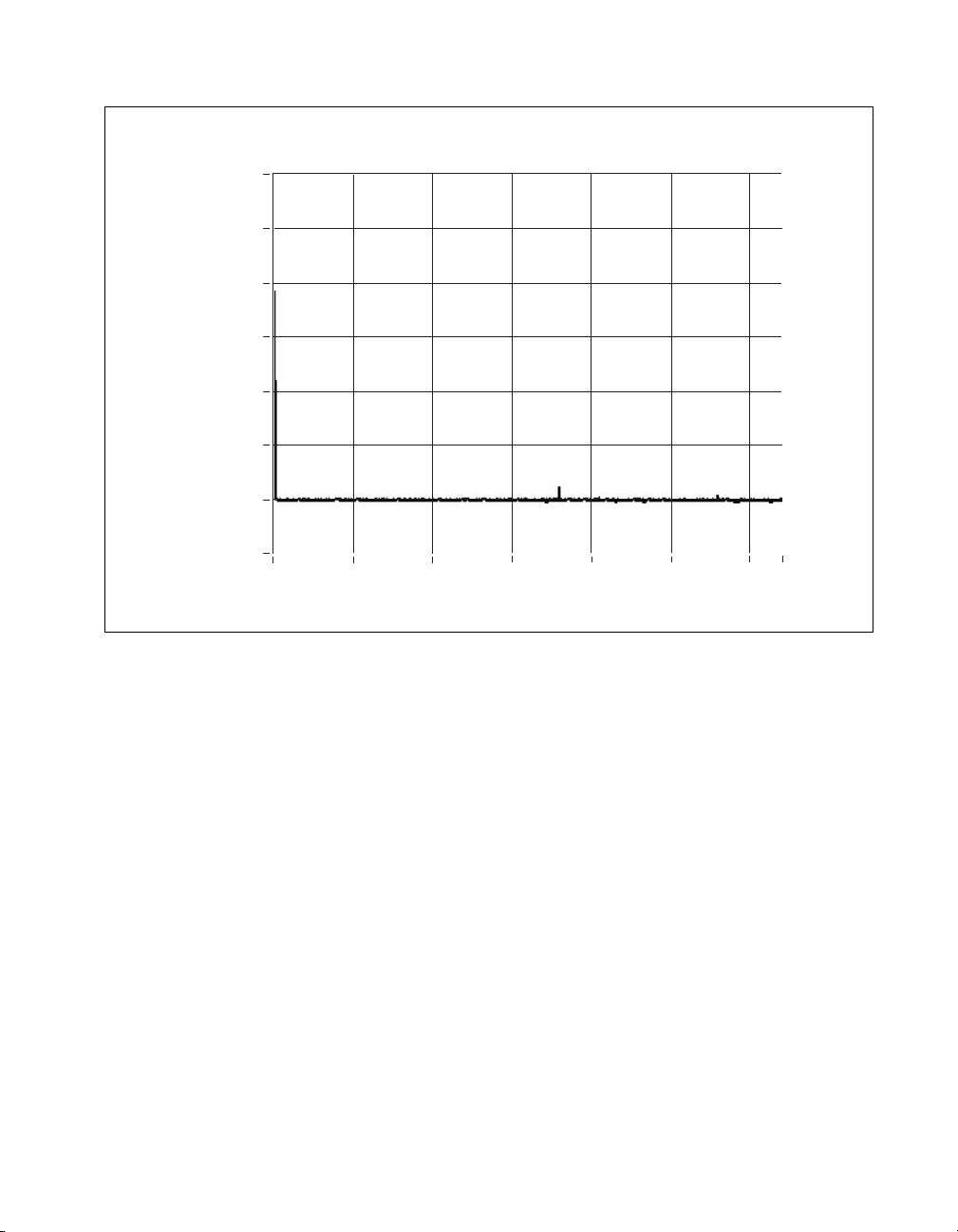
Amplitude
Amplitude (dBm)
Typical Results
–70.00
–80.00
–90.00
–100.00
–110.00
–120.00
–130.00
–140.00
0.0 5.0M 20.0M 25.0M 32.0M
15.0M10.0M
Frequency (Hz)
Figure 1. Noise Density (Dither Disabled, Input Terminated)
Average noise density
(dither off) .............................................. < –129 dBm/Hz
Signal-to-noise ratio
9 dBm signal, full bandwidth.......... >62 dB
Harmonic distortion (single tone, 0 dBm signal;
includes aliased harmonic distortion)
4–15 MHz, dither enabled .............. < –77 dBm
0–32 MHz, dither disabled.............. <–71 dBm
© National Instruments Corporation 3 NI PXI-5621 Specifications
Page 4

Typical Results
0.00
–10.00
–20.00
–30.00
–40.00
–50.00
–60.00
Amplitude (dBm)
–70.00
–80.00
–90.00
–100.00
–110.00
30.5M 30.6M 30.7M 31.1M 31.3M 31.5M
30.9M30.8M 31.0M 31.2M 31.4M
Frequency (Hz)
Figure 2. Intermodulation Distortion
Intermodulation distortion
(2-tone, 0 dBm signals, 200 kHz separation)
4–15 MHz, dither enabled ...............< –86 dBm
0–32 MHz, dither disabled ..............<–78 dBm
Residual responses (input terminated)....< –75 dBm
NI PXI-5621 Specifications 4 ni.com
Page 5

Typical Results
0.20
0.10
0.00
–0.10
–0.20
–0.30
–0.40
Amplitude (dB)
–0.50
–0.60
–0.70
–0.80
0.0 2.5 5.0 7.5 10.0 12.5 15.0 17.5 20.0 22.5 25.0 27.5 30.0 32.0
Frequency (MHz)
Figure 3. Frequency Response (0.1–32 MHz)
Frequency response (4–25 MHz)
Relative (to response at 15 MHz) ... < ±0.25 dB
Absolute .......................................... <±0.6 dB
Absolute (using calibration table)... <±0.5 dB
© National Instruments Corporation 5 NI PXI-5621 Specifications
Page 6

Phase
Typical Results
20.00E–9
18.00E–9
16.00E–9
14.00E–9
12.00E–9
10.00E–9
8.00E–9
Group Delay (ns)
6.00E–9
4.00E–9
2.00E–9
0.00E+0
–2.00E–9
0.0E+0 5.0E+6 10.0E+6 20.0E+6 25.0E+6 32.0E+6
15.0E+6
Frequency (Hz)
Figure 4. Group Delay versus Frequency
Group delay variation
(5–25 MHz) ............................................9 ns
pk–pk
Group delay variation
(0.5–30 MHz) .........................................26 ns
pk–pk
DDC
Decimation rate.......................................32–4,096
DDC tuning resolution............................0.014901 Hz
NI PXI-5621 Specifications 6 ni.com
Page 7

Triggering
Modes..................................................... Immediate, software, digital
Sources ...................................................PFI 1, PXI<0..7>, PXI STAR
Export..................................................... PFI 1, PXI<0..7>
Slope....................................................... Rising, falling
Pretrigger depth...................................... Up to 32 MS
Posttrigger depth ....................................Up to 32 MS
Minimum pulse width ............................100 ns
External Trigger (PFI 1)
PFI 1 connector ...................................... SMB male
Trigger level...........................................TTL
Max input voltage .................................. 5.5 V
External Frequency Reference Input
Connector (REF CLK IN)...................... SMA female
Impedance .............................................. 50 Ω nominal
Input amplitude ......................................–5 to +15 dBm
Max non-operating input level ............... +20 dBm
Max DC input voltage............................ ±3.5 VDC
Frequency range..................................... 10 MHz ±40 ppm
Crosstalk from reference input............... <–85 dB
Calibration
Calibration interval ................................ 1 year
© National Instruments Corporation 7 NI PXI-5621 Specifications
Page 8

Environmental Specifications
Warm-up time.........................................10 minutes
Operating environment
Ambient temperature .......................0–50 °C
Humidity..........................................10–90%, noncondensing
Storage environment
Storage temperature.........................–20 to 70 °C
Humidity..........................................5–95%, noncondensing
Maximum altitude...................................2,000 meters
Pollution Degree .....................................2
Indoor use only
Power Requirements
+3.3 VDC (±5%) ....................................<650 mA
+5 VDC (±5%) .......................................<1.5 A
+12 VDC (±5%) .....................................<650 mA
–12 VDC (±5%)......................................<75 mA
Maximum Working Voltage
Channel-to-earth .....................................2.23 V operating,
3.0 V nonoperating;
Installation Category I
Safety
Meets the requirements of the following standards for safety for electrical
equipment for measurement, control, and laboratory use:
EN 61010-1:1993/A2:1995, IEC 61010-1:1990/A2:1995,
UL 3101-1:1993, UL 3111-1:1994, UL 3121:1998,
CAN/CSA C22.2 no. 1010.1:1992/A2:1997 d.
NI PXI-5621 Specifications 8 ni.com
Page 9

Electromagnetic Compatibility
CE, C-Tick, and FCC Part 15 (Class A) compliant
Electrical emissions................................ EN 55011 Class A at 10 m FCC
Electrical immunity................................ Evaluated to EN
Note For full EMC compliance, you must operate this device with shielded cabling. In
addition, all covers and filler panels must be installed. See the Declaration of Conformity
(DoC) for this product for any additional regulatory compliance information. To obtain the
DoC for this product, click Declaration of Conformity at
Web site lists the DoCs by product family. Select the appropriate product family, followed
by your product, and a link to the DoC (in Adobe Acrobat format) appears. Click the
Acrobat icon to download or read the DoC.
Dimensions
PXI-5621 (1 PXI slot) ............................ 10 by 16 by 2.0 cm
Certifications and Compliances
CE Mark Compliance
Part 15A above 1 GHz
61326:1997/A1:1998, Table 1
ni.com/hardref.nsf. This
(3.9by6.3by0.8in.)
Conductive Immunity
When tested as specified in EN 61000-4-6 at 3 V
is within specifications except at the test frequency. A spurious signal of up
to –45 dBm may appear at the test frequency.
© National Instruments Corporation 9 NI PXI-5621 Specifications
, the spurious response
rms
 Loading...