

Page 1

CALIBRATION PROCEDURE
NI PXI-5422
This document contains step-by-step instructions for writing a calibration
procedure for the NI PXI-5422 arbitrary waveform generator.
Contents
Conventions ............................................................................................ 1
Introduction.............................................................................................2
What Is Calibration? ........................................................................ 2
Self-Calibration ........................................................................ 2
External Calibration.................................................................. 2
Why Should You Calibrate? ............................................................ 2
How Often Should You Calibrate? .................................................. 3
Software and Documentation Requirements...........................................3
Software ........................................................................................... 3
Documentation.................................................................................5
Self-Calibration Procedures .................................................................... 5
MAX ................................................................................................ 5
FGEN Soft Front Panel.................................................................... 6
NI-FGEN ......................................................................................... 6
External Calibration Options .................................................................. 7
Complete Calibration....................................................................... 7
Optional Calibration ........................................................................ 9
External Calibration Requirements ......................................................... 11
Test Equipment ................................................................................ 11
Test Conditions ................................................................................ 11
External Calibration Procedures ............................................................. 12
Writing Your Calibration Procedure................................................12
Calibration Procedures in LabVIEW........................................ 12
Calibration Procedures in LabWindows/CVI ...........................12
Calibration Procedures in C......................................................12
Verifying NI PXI-5422 Specifications ............................................13
Verifying the Oscillator Frequency Accuracy.......................... 15
Verifying the DC Gain and Offset Accuracy ...........................17
Adjusting the NI PXI-5422.............................................................. 31
Initializing the External Calibration Session ............................35
Page 2

Adjusting the Analog Output ....................................................35
Adjusting the Oscillator Frequency...........................................52
Adjusting the Calibration ADC.................................................55
Closing the External Adjustment Session.................................60
Calibration Utilities .................................................................................61
MAX.................................................................................................61
FGEN SFP........................................................................................61
NI-FGEN ..........................................................................................62
Where to Go for Support .........................................................................63
Conventions
The following conventions are used in this manual:
» The » symbol leads you through nested menu items and dialog box options
to a final action. The sequence File»Page Setup»Options directs you to
pull down the File menu, select the Page Setup item, and select Options
from the last dialog box.
This icon denotes a note, which alerts you to important information.
This icon denotes a caution, which advises you of precautions to take to
avoid injury, data loss, or a system crash. When this symbol is marked on
a product, refer to the Read Me First: Safety and Radio-Frequency
Interference document for information about precautions to take.
bold Bold text denotes items that you must select or click in the software, such
as menu items and dialog box options. Bold text also denotes parameter
names.
italic Italic text denotes variables, emphasis, a cross reference, or an introduction
to a key concept. This font also denotes text that is a placeholder for a word
or value that you must supply.
monospace Text in this font denotes text or characters that you should enter from the
keyboard, sections of code, programming examples, and syntax examples.
This font is also used for the proper names of disk drives, paths, directories,
programs, subprograms, subroutines, device names, functions, operations,
variables, filenames, and extensions.
Introduction
This document contains instructions for calibrating the NI PXI-5422
arbitrary waveform generator. This calibration procedure is intended for
metrology labs. It describes specific programming steps for writing an
external calibration procedure for the NI PXI-5422.
NI PXI-5422 Calibration Procedure 2 ni.com
Page 3

What Is Calibration?
Calibration consists of verifying the output accuracy of a device and
correcting for any output error. Verification is measuring the performance
of a device and comparing the results to the specifications of the device.
NI calibrates every NI PXI-5422 at the factory. During the factory
calibration process, the calibration constants are stored in an onboard
EEPROM. These values are loaded from this EEPROM and used as needed
by the NI PXI-5422.
The NI PXI-5422 supports two types of calibration: self-calibration (or
internal calibration) and external calibration.
Self-Calibration
Self-calibration, also known as internal calibration, uses a software
command and requires no external connections. Self-calibration improves
output accuracy by compensating for variables, such as temperature and
time, that may have changed since the last external calibration.
Self-calibration retains the traceability of the external calibration.
External Calibration
External calibration is generally performed at either NI or a metrology lab.
This procedure replaces all calibration constants in the EEPROM and is
equivalent to a factory calibration at NI. Because the external calibration
procedure changes all EEPROM constants, it invalidates the original
calibration certificate. If an external calibration is done with a traceable
instrument, a new calibration certificate can be issued.
Why Should You Calibrate?
The accuracy of electronic components drifts with time and temperature,
which can affect output accuracy as a device ages. Calibration verifies
that the NI PXI-5422 still meets its specified accuracy and NI standards. If
adjustments are necessary, calibration makes the adjustments to restore
the accuracy.
How Often Should You Calibrate?
Self-calibration can be performed as necessary to compensate for
environmental changes.
Caution Although you can use self-calibration repeatedly, self-calibrating the
NI PXI-5422 more than a few times a day may cause excessive wear on the relays over
time.
© National Instruments Corporation 3 NI PXI-5422 Calibration Procedure
Page 4

The output accuracy requirements of your application determine how often
you should externally calibrate the NI PXI-5422. NI recommends that you
perform a complete external calibration at least once every two years.
You can shorten this interval based on the accuracy demands of your
application. Refer to the External Calibration Options section for more
information.
Software and Documentation Requirements
This section describes the software and documentation required for both
self-calibration and external calibration.
Software
Calibrating the NI PXI-5422 requires installing NI-FGEN version 2.2 or
later on the calibration system. You can download NI-FGEN from the
Instrument Driver Network at
programming the Self-Calibration Procedures and the External
Calibration Procedures in the LabVIEW, LabWindows
application development environments (ADEs). When you install
NI-FGEN, you only need to install support for the ADE that you intend to
use.
NI-FGEN 2.2 or later includes all the functions and attributes necessary for
calibrating the NI PXI-5422. For LabWindows/CVI, the NI-FGEN
function panel (
LabVIEW support is in the
appear in the function palette.
niFgen.fp) provides help about the functions available.
ni.com/idnet. NI-FGEN supports
niFgen.llb file, and all calibration functions
™
/CVI™, and C
Calibration functions are C function calls or LabVIEW VIs in NI-FGEN.
In this document, the C function call is shown first, followed by the
corresponding LabVIEW VI, or NI-FGEN LabVIEW property node,
in parentheses. The C function calls are valid for any compiler capable of
NI PXI-5422 Calibration Procedure 4 ni.com
Page 5

calling a 32-bit DLL. Many of the functions use constants defined in the
niFgen.h file. To use these constants in C, you must include niFgen.h
in your code when you write the calibration procedure. Refer to Table 1
for file locations.
Table 1. Calibration File Locations
File Name and Location Description
IVI\Bin\niFgen_32.dll The NI-FGEN library, which provides the
functionality for calibrating the
NI PXI-5422.
IVI\Lib\msc\niFgen.lib Allows you to create applications that call
functions in the
niFgen_32.dll:
• For Microsoft Visual C/C++, link to
msc\niFgen.lib.
• For LabWindows/CVI, link to the library
appropriate to your current compatibility
mode (
msc for Microsoft Visual C/C++).
IVI\Include\niFgen.h A header file for the accessible functions in
the
niFgen_32.dll. You must include this
file in any C code that you write to call these
functions.
<LabVIEW>\instr.lib\niFgen\niFgen.llb
(LabVIEW)
IVI\Drivers\niFgen\niFgen.fp
(CVI)
The calibration process is described in the Self-Calibration Procedures and
the External Calibration Procedures sections, including step-by-step
instructions on calling the appropriate calibration functions.
Contains VIs that correspond to the functions
in the
niFgen_32.dll.
Contains the function panels for the function
in the
niFgen32.dll.
© National Instruments Corporation 5 NI PXI-5422 Calibration Procedure
Page 6

Documentation
For information about NI-FGEN and the NI PXI-5422, you may find the
following documents helpful:
• NI Signal Generators Getting Started Guide
• NI Signal Generators Help
• NI PXI-5422 Specifications
• NI-FGEN Instrument Driver Quick Reference Guide
The NI Signal Generators Getting Started Guide provides instructions for
installing and configuring NI signal generators.
The NI Signal Generators Help includes detailed information about
the NI PXI-5422 and the NI-FGEN functions. You can access this help file
by selecting Start»Programs»National Instruments»NI-FGEN»
Documentation»NI Signal Generators Help. For the latest versions
of NI documentation, refer to
Self-Calibration Procedures
The NI PXI-5422 is capable of performing self-calibration, which adjusts
the gain and offset of the main and direct analog paths. Self-calibration
exclusively uses an onboard A/D converter (ADC) to measure the output
voltage. You can implement self-calibration on the NI PXI-5422 by
following procedures similar to the Verifying the DC Gain and Offset
Accuracy and the Adjusting the Analog Output procedures. However,
output impedance, oscillator frequency, and the calibration ADC cannot be
adjusted during self-calibration.
ni.com/manuals.
You can initiate self-calibration interactively from Measurement &
Automation Explorer (MAX) or from the FGEN Soft Front Panel (SFP).
Alternately, you can initiate self-calibration programmatically using
NI-FGEN.
MAX
To initiate self-calibration from MAX, complete the following steps:
1. Launch MAX.
2. Select My System»Devices and Interfaces»NI-DAQmx Devices.
NI PXI-5422 Calibration Procedure 6 ni.com
Page 7

3. Select the device that you want to calibrate.
4. Initiate self-calibration in one of the following ways:
FGEN Soft Front Panel
To initiate self-calibration from the FGEN SFP, complete the following
steps:
1. Select the device that you want to calibrate using the Device
2. Open the Calibration dialog box (Utility»Calibration).
3. Click Perform self-calibration.
NI-FGEN
To self-calibrate the NI PXI-5422 programmatically using NI-FGEN,
complete the following steps:
1. Call
2. Call
3. Call
•Click Self-Calibrate in the upper right corner.
• Right-click the device name under Devices and Interfaces,
and select Self-Calibrate from the drop-down menu.
Configuration dialog box (Edit»Device Configuration).
niFgen_init (niFgen Initialize VI) to open an NI-FGEN session
using the following parameters:
• resourceName: The name of the device that you want to calibrate.
You can find this name under Devices and Interfaces in MAX.
• IDQuery:
• resetDevice: VI_TRUE
• vi: A pointer to a ViSession. The variable passed by reference
through this parameter receives the value that identifies the
session created by this function. This value acts as the session
handle and is passed as the first parameter to all subsequent
NI-FGEN functions.
niFgen_SelfCal (niFgen Self Cal VI) using the following
parameter:
• vi: The session handle returned from
niFgen_close (niFgen Close VI) to close the NI-FGEN session
using the following parameter:
• vi: The session handle returned from
VI_TRUE
niFgen_init
niFgen_init
© National Instruments Corporation 7 NI PXI-5422 Calibration Procedure
Page 8

External Calibration Options
External calibration involves both verification and adjustment. Verification
is the process of testing the device to ensure that the output accuracy is
within certain specifications. You can use verification to ensure that the
adjustment process was successful or to determine if the adjustment
process needs to be performed.
Adjustment is the process of measuring and compensating for device
performance to improve the output accuracy. Performing an adjustment
updates the calibration date, resetting the calibration interval. The device is
guaranteed to meet or exceed its published specifications for the duration
of the calibration interval.
This document provides two sets of test limits for most verification stages,
the calibration test limits and the published specifications. The calibration
test limits are more restrictive than the published specifications. If all of
the output errors determined during verification fall within the calibration
test limits, the device is guaranteed to meet or exceed its published
specifications for a full calibration interval (two years). For this reason,
you must verify against the calibration test limits when performing
verification after adjustment.
If all of the output errors determined during verification fall within the
published specifications, but not within the calibration test limits, the
device meets its published specifications. However, the device may not
remain within these specifications for another two years. The device will
meet published specifications for the rest of the current calibration interval.
In this case, you can perform an adjustment if you want to improve
the output accuracy or reset the calibration interval. If some output
errors determined during verification do not fall within the published
specifications, you must perform an adjustment to restore the device
operation to its published specifications.
The Complete Calibration section describes the recommended
calibration procedure. The Optional Calibration section describes
alternate procedures that allow you to skip adjustment if the device
already meets its calibration test limits or published specifications.
Complete Calibration
Performing a complete calibration is the recommended way to guarantee
that the NI PXI-5422 meets or exceeds its published specifications for a
two-year calibration interval. At the end of the complete calibration
procedure, you verify that the output error falls within the calibration test
limits. Figure 1 shows the programming flow for complete calibration.
NI PXI-5422 Calibration Procedure 8 ni.com
Page 9
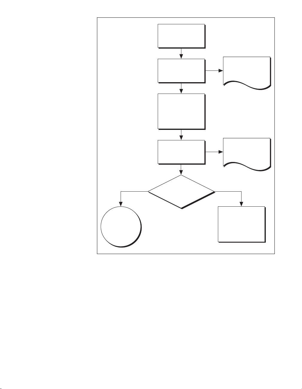
Self-Calibrate
Verify
Adjust
(Cal Dates and
Temperatures
Updated)
Verify
Document
Pre-Adjustment
Results
Document
Post-Adjustment
Results
Calibration/
Verification
Complete
Ye s N o
Meets
Calibration
Test Limits?
Review
Verification/
Adjustment
Procedure or
Return Device
Figure 1. Complete Calibration Programming Flow
© National Instruments Corporation 9 NI PXI-5422 Calibration Procedure
Page 10

Optional Calibration
Note Regardless of the results of the first verification, if you choose to perform an
adjustment you must verify that the output error falls within the calibration test limits
at the end of the calibration procedure.
You can choose to skip the adjustment steps of the calibration procedure
if the output error is within the calibration test limits or the published
specifications during the first verification. If all of the output errors
determined during the first verification fall within the calibration test
limits, the device is guaranteed to meet or exceed its published
specifications for a full calibration interval. In this case, you can update
the calibration date, effectively resetting the calibration interval, without
actually performing an adjustment. Refer to the Adjusting the NI PXI-5422
section for more information.
If all of the output errors determined during the first verification fall within
the published specifications, but not within the calibration test limits,
adjustment is also optional. However, you cannot update the calibration
date because the device will not necessarily operate within the published
specifications for an additional two years.
Figure 2 shows the programming flow for the optional calibration.
NI PXI-5422 Calibration Procedure 10 ni.com
Page 11
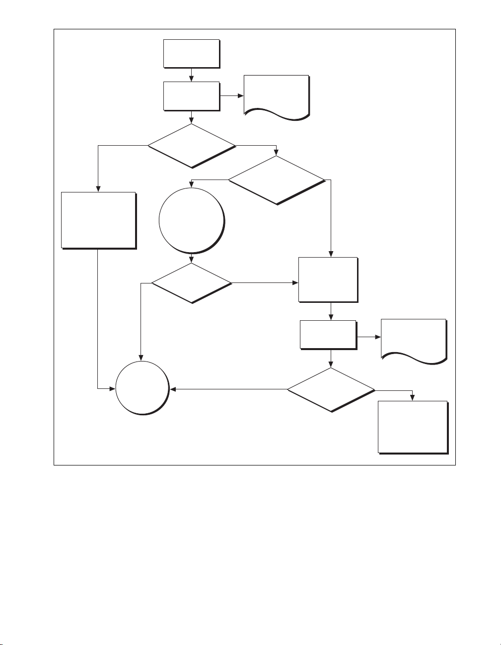
Self-Calibrate
Verify
Document
Pre-Adjustment
Results
Update Calibration
Dates and
Temperatures
Without Adjusting
Calibration/
Verification
Ye s N o
Complete
Meets
Calibration
Test Limits?
Ye s No
Results
Within
Published Specs
(Adjustment
Optional)
Adjust
Anyway?
Specifications?
Ye sNo
Meets
Published
Ye s
Adjust
(Cal Dates and
Temperatures
Updated)
Verify
Meets
Calibration
Test Limits?
Document
Post-Adjustment
Results
No
Review
Verification/
Adjustment
Procedure or
Return Device
Figure 2. Optional Calibration Programming Flow
© National Instruments Corporation 11 NI PXI-5422 Calibration Procedure
Page 12

External Calibration Requirements
This section describes the test equipment and test conditions required for
calibration.
Test Equipment
External calibration requires different equipment for each applicable
specification. Refer to Table 2 for a list of equipment.
Table 2. Equipment Required for Calibrating the NI PXI-5422
Instrument
Digital multimeter
(DMM)
Male banana to
female BNC adapter
Male BNC to
female SMB cable
Spectrum analyzer or
frequency meter
Male BNC to
female SMB cable
Test Conditions
Applicable
Specification
DC gain and offset DC accuracy ≤ ±50 ppm
Frequency accuracy Ability to measure
Follow these guidelines to optimize the connections and the environment
during calibration:
• Keep connections to the NI PXI-5422 short.
• Keep relative humidity below 80%.
• Maintain a temperature between 18 °C and 28 °C.
• Observe the 15-minute warm-up time.
Minimum
Specifications
Resolution ≤1 µV
— —
50 Ω, RG-223 —
10 MHz or higher
sine waves
Frequency accuracy
to ±500 ppb
50 Ω, RG-223 —
Recommended
Instrument
NI PXI-4070
Agilent HP 34401A
Keithley 2000
NI PXI-5660
Agilent HP 8560E
Agilent HP 53131A
or HP 53132A
with timebase option
001, 010, or 012
NI PXI-5422 Calibration Procedure 12 ni.com
Page 13

External Calibration Procedures
The complete external calibration procedure consists of self-calibrating,
verifying the performance of the NI PXI-5422, adjusting the calibration
constants, and verifying again after the adjustments. In some cases, the
complete calibration procedure may not be required. Refer to the External
Calibration Options section for more information.
The external calibration procedure automatically stores the calibration date
to allow traceability.
Writing Your Calibration Procedure
Before you begin to write your calibration program, review the
programming flows in Figures 1 and 2.
Calibration Procedures in LabVIEW
To write calibration procedures in LabVIEW, you must use the
VIs included in the
appear within the NI-FGEN Calibration palette under Functions»
Instrument I/O»Instruments Drivers»NI-FGEN»Calibration.
Calibration Procedures in LabWindows/CVI
To write calibration procedures in LabWindows/CVI, you must use the
functions included in the
the calibration functions under the Calibration class node.
niFgen.llb file. After installation, these VIs
niFgen.fp file. After installation, you can locate
Calibration Procedures in C
To write calibration procedures in C, you must include the niFgen.h
file in the code that calls the calibration functions, and you must link
the
niFgen.lib file into the build of your executable.
© National Instruments Corporation 13 NI PXI-5422 Calibration Procedure
Page 14

Verifying NI PXI-5422 Specifications
Note Always self-calibrate the NI PXI-5422 before beginning a verification procedure.
This section provides instructions for verifying the NI PXI-5422
specifications. This section also includes instructions for updating the
calibration cycle.
Verification determines whether the device is performing within its
specifications prior to external adjustment. Verification and external
adjustment together comprise a complete calibration. To verify that the
NI PXI-5422 still meets its specifications, you must use NI-FGEN to
control the NI PXI-5422.
The steps in the verification procedures describe the code that you use to
generate the appropriate signals, as well as the NI-FGEN function calls
that you make to verify specifications.
You can verify the following specifications for the NI PXI-5422:
• Oscillator frequency accuracy
• DC gain and offset accuracy
The verification procedure for each of these specifications includes setting
up, programming, and cleaning up.
Note If any of these tests fail immediately after you perform an external adjustment, verify
that you have met the required test conditions before you return the NI PXI-5422 to NI for
repair.
Refer to Table 2 for information about which instrument to use for
verifying each specification. Refer to Figure 3 for the names and locations
of the NI PXI-5422 front panel connectors.
NI PXI-5422 Calibration Procedure 14 ni.com
Page 15
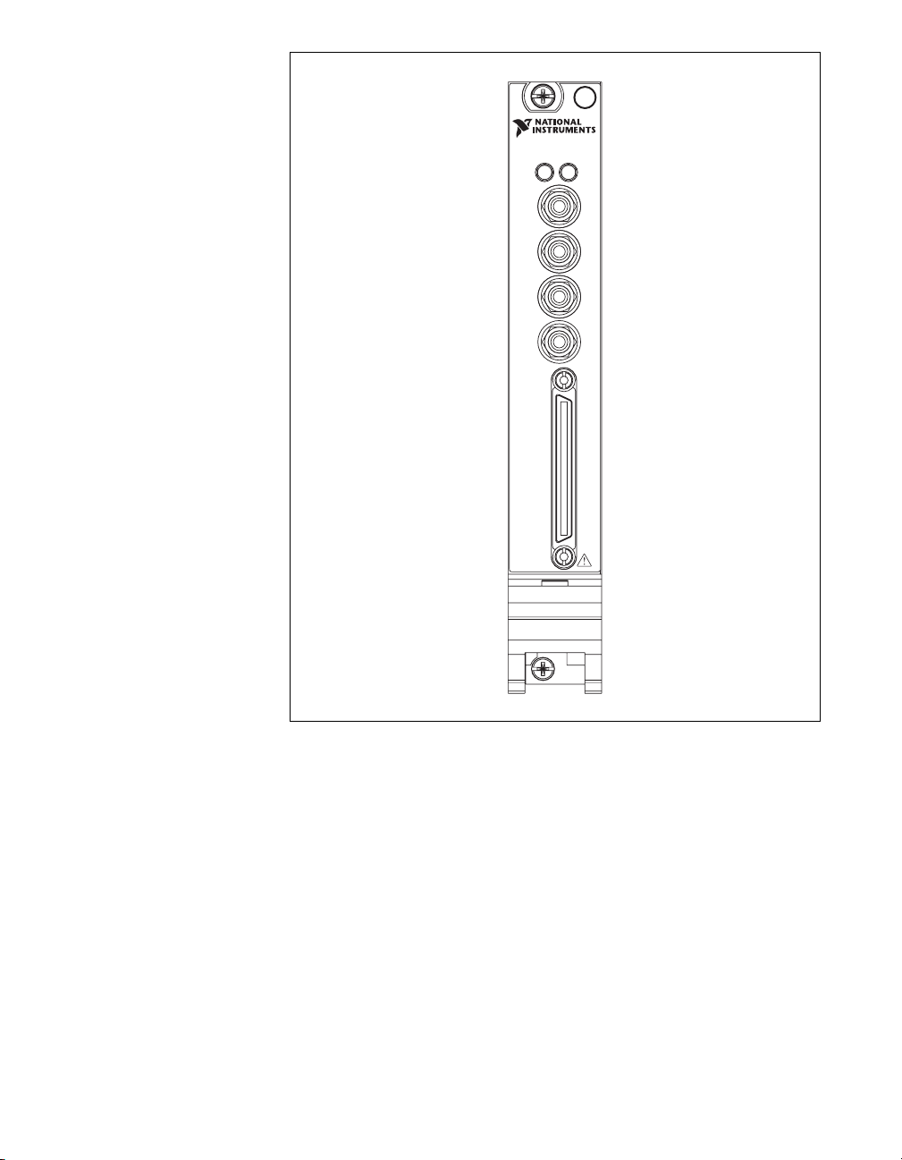
NI PXI-5422
16-Bit 200 MS/s AWG
ACCESS ACTIVE
CH 0
CLK
IN
PFI 0
PFI 1
DIGITAL DATA & CONTROL
Figure 3. NI PXI-5422 Front Panel Connectors
© National Instruments Corporation 15 NI PXI-5422 Calibration Procedure
Page 16

Verifying the Oscillator Frequency Accuracy
This test verifies the frequency accuracy of the oscillator on the
NI PXI-5422. The verification involves generating a 10 MHz sine wave
with the NI PXI-5422 and measuring the sine wave frequency with one of
the instruments from Table 2.
To verify the frequency accuracy of the oscillator on the NI PXI-5422,
complete the following steps:
1. Connect the NI PXI-5422 CH 0 front panel connector to the instrument
measuring the frequency accuracy with a male BNC to female SMB
cable.
2. Call
3. Call
4. Call niFgen_SetAttributeViReal64 to set the gain (niFgen
niFgen_init (niFgen Initialize VI) using the following
parameters:
• resourceName: The name of the device that you want to verify.
You can find this name under Devices and Interfaces in MAX.
• IDQuery:
VI_TRUE
• resetDevice: VI_TRUE
• vi: A pointer to a ViSession. The variable passed by reference
through this parameter receives the value that identifies the
session created by this function. This value acts as the session
handle and is passed as the first parameter to all subsequent
NI-FGEN functions.
niFgen_SetAttributeViReal64 to set the sample rate
(niFgen property node: Arbitrary Waveform Output»Sample Rate)
using the following parameters:
• vi: The session handle returned from
niFgen_init
• channelName: "0"
• attributeID: NIFGEN_ATTR_ARB_SAMPLE_RATE
• value: 200000000
property node: Arbitrary Waveform Output»Arbitrary Waveform
Gain) using the following parameters:
• vi: The session handle returned from
niFgen_init
• channelName: "0"
• attributeID: NIFGEN_ATTR_ARB_GAIN
• value: 1
Note You can adjust this value based on which measuring device you use.
NI PXI-5422 Calibration Procedure 16 ni.com
Page 17

5. Call niFgen_SetAttributeViReal64 to set the offset (niFgen
property node: Arbitrary Waveform Output»Arbitrary Waveform
Offset) using the following parameters:
• vi: The session handle returned from
niFgen_init
• channelName: "0"
• attributeID: NIFGEN_ATTR_ARB_OFFSET
• value: 0
Note You can adjust this value based on which measuring device you use.
6. Call
niFgen_SetAttributeViBoolean to set the analog filter state
(niFgen property node: Output Attributes»Analog Filter Enabled)
using the following parameters:
• vi: The session handle returned from
niFgen_init
• channelName: "0"
• attributeID: NIFGEN_ATTR_ANALOG_FILTER_ENABLED
• value: VI_TRUE
7. Generate an array of waveform samples. The waveform should have
20 samples per cycle with a total of 500 samples. This configuration
results in 25 sine wave cycles. Because you set the sample rate to 200
MS/s and because you are using 20 samples per cycle, the resulting
waveform is a 10 MHz sine wave.
Note The sample values of this waveform must fall between –1.0 and 1.0.
8. Call
niFgen_CreateArbWaveform (niFgen Create Arbitrary
Waveform VI) using the following parameters:
• vi: The session handle returned from
• wfmSize: The size in samples (
niFgen_init
500) of the waveform you created
in step 7
• wfmData: The array of waveform samples that you created in
step 7
• wfmHandle: The variable passed by reference through this
parameter receives the value (waveform handle) that identifies
the waveform created by this function.
9. Call
niFgen_InitiateGeneration (niFgen Initiate Generation VI)
to initiate the waveform generation using the following parameter:
• vi: The session handle returned from
niFgen_init
10. Measure the frequency out of the NI PXI-5422.
© National Instruments Corporation 17 NI PXI-5422 Calibration Procedure
Page 18

A frequency error of 45 Hz for a 10 MHz signal corresponds to an
error of 4.5 ppm. This limit accounts for the initial accuracy and the
frequency deviation caused by temperature and aging. Refer to Table 3
for frequency ranges.
Table 3. Frequency Ranges
Calibration Test Limit Published Specifications ±25 ppm
Low High Low High
9,999,955 Hz 10,000,045 Hz 9,999,750 Hz 10,000,250 Hz
11. Call
niFgen_AbortGeneration (niFgen Abort Generation VI) to
abort the waveform generation using the following parameter:
• vi: The session handle returned from
niFgen_init
12. Call niFgen_close (niFgen Close VI) to close the instrument
driver session, to destroy the instrument driver session and all of
its properties, and to release any memory resources NI-FGEN uses.
Use the following parameter:
• vi: The session handle returned from
niFgen_init
Verifying the DC Gain and Offset Accuracy
This test verifies the DC gain and offset accuracy of the NI PXI-5422 into
a high-impedance load by generating a number of DC voltages and offsets,
measuring the voltage with a DMM, and comparing the NI PXI-5422 to the
error limits.
The DC gain and offset accuracy verification procedure has three
sub-procedures that verify the following:
• Main analog path gain
• Main analog path offset
• Direct path gain
Verifying the Main Analog Path Gain
To verify the gain of the NI PXI-5422 main analog path, complete the
following steps:
1. Connect the NI PXI-5422 CH 0 front panel connector to the DMM for
measuring DC gain and offset accuracy.
2. Call
niFgen_init (niFgen Initialize VI) using the following
parameters:
• resourceName: The name of the device that you want to verify.
You can find this name under Devices and Interfaces in MAX.
NI PXI-5422 Calibration Procedure 18 ni.com
Page 19

• IDQuery: VI_TRUE
• resetDevice: VI_TRUE
• vi: A pointer to a ViSession. The variable passed by reference
through this parameter receives the value that identifies the
session created by this function. This value acts as the session
handle and is passed as the first parameter to all subsequent
NI-FGEN functions.
3. Call
niFgen_SetAttributeViBoolean to set the analog filter state
(niFgen property node: Output Attributes»Analog Filter Enabled)
using the following parameters:
• vi: The session handle returned from
niFgen_init
• channelName: "0"
• attributeID: NIFGEN_ATTR_ANALOG_FILTER_ENABLED
• value: VI_FALSE
4. Call niFgen_SetAttributeViReal64 to set the load impedance
(niFgen property node: Output Attributes»Load Impedance)
using the following parameters:
• vi: The session handle returned from
niFgen_init
• channelName: "0"
• attributeID:
NIFGEN_ATTR_LOAD_IMPEDANCE
• value: 10000000000
5. Call niFgen_SetAttributeViInt32 to set the analog path (niFgen
property node: Output Attributes»Analog Path) using the following
parameters:
• vi: The session handle returned from
niFgen_init
• channelName: "0"
• attributeID: NIFGEN_ATTR_ANALOG_PATH
• value: NIFGEN_VAL_MAIN_ANALOG_PATH
6. Call niFgen_SetAttributeViReal64 to set the output impedance
(niFgen property node: Basic Operation»Output Impedance) using
the following parameters:
• vi: The session handle returned from
niFgen_init
• channelName: "0"
• attributeID: NIFGEN_ATTR_OUTPUT_IMPEDANCE
• value: 50
© National Instruments Corporation 19 NI PXI-5422 Calibration Procedure
Page 20

7. Call niFgen_SetAttributeViBoolean to enable the analog output
(niFgen property node: Basic Operation»Output Enabled) using
the following parameters:
• vi: The session handle returned from
niFgen_init
• channelName: "0"
• attributeID: NIFGEN_ATTR_OUTPUT_ENABLED
• value: VI_TRUE
8. Create an array of waveform samples for the positive full-scale DC
waveform. This array should contain 500 samples with each sample
having the value
9. Call
niFgen_CreateArbWaveform (niFgen Create Arbitrary
1.0 (representation: double).
Waveform VI) using the following parameters:
• vi: The session handle returned from
• wfmSize: The size in samples (
niFgen_init
500) of the waveform you created
in step 8
• wfmData: The array of waveform samples that you created in
step 8
• wfmHandle: The variable passed by reference through this
parameter receives the value (waveform handle) that identifies the
waveform created by this function (positive full-scale handle).
10. Create an array of waveform samples for the negative full-scale DC
waveform. This array should contain 500 samples with each sample
having the value
11. Call
niFgen_CreateArbWaveform (niFgen Create Arbitrary
–1.0 (representation: double).
Waveform VI) using the following parameters:
• vi: The session handle returned from
• wfmSize: The size in samples (
niFgen_init
500) of the waveform that you
created in step 10
• wfmData: The array of waveform samples that you created in
step 10
• wfmHandle: The variable passed by reference through this
parameter receives the value (waveform handle) that identifies the
waveform created by this function (negative full-scale handle).
NI PXI-5422 Calibration Procedure 20 ni.com
Page 21

12. Call niFgen_SetAttributeViReal64 to set the offset (niFgen
property node: Arbitrary Waveform Output»Arbitrary Waveform
Offset) using the following parameters:
• vi: The session handle returned from
niFgen_init
• channelName: "0"
• attributeID: NIFGEN_ATTR_ARB_OFFSET
• value: 0
13. Repeat steps 14 through 24 for each of the 24 iterations listed in
Table 4, changing the Gain value for each iteration. You can use
Table 4 to record the results of these steps.
© National Instruments Corporation 21 NI PXI-5422 Calibration Procedure
Page 22

Spec
Published
Test Li mi t
Calibration
Error
Negative
Full-Scale
Error
Positive
Full-Scale
Negative
Measured
Full-Scale
Positive
Measured
Full-Scale
(Volts)
(Volts)
2
(Volts)
1
(Volts)
(Volts)
(Volts)
(Volts)
Ideal Negative
Ideal
Positive
Full-Scale
Full-Scale
(Volts)
1 12.000000 12.000000 –12.000000 ±0.019700 ±0.048500
2 10.000000 10.000000 –10.000000 ±0.016500 ±0.040500
3 7.000000 7.000000 –7.000000 ±0.011700 ±0.028500
4 5.000000 5.000000 –5.000000 ±0.008500 ±0.020500
5 3.500000 3.500000 –3.500000 ±0.006100 ±0.014500
6 2.500000 2.500000 –2.500000 ±0.004500 ±0.010500
7 2.000000 2.000000 –2.000000 ±0.003700 ±0.008500
8 1.650000 1.650000 –1.650000 ±0.003140 ±0.007100
9 1.250000 1.250000 –1.250000 ±0.002500 ±0.005500
10 0.850000 0.850000 – 0.850000 ±0.001860 ±0.003900
11 0.600000 0.600000 – 0.600000 ±0.001460 ±0.002900
12 0.415000 0.415000 – 0.415000 ±0.001164 ±0.002160
13 0.300000 0.300000 – 0.300000 ±0.000980 ±0.001700
14 0.205000 0.205000 – 0.205000 ±0.000828 ±0.001320
15 0.150000 0.150000 – 0.150000 ±0.000740 ±0.001100
16 0.105000 0.105000 – 0.105000 ±0.000668 ±0.000920
17 0.075000 0.075000 – 0.075000 ±0.000620 ±0.000800
18 0.055000 0.055000 – 0.055000 ±0.000588 ±0.000720
19 0.037500 0.037500 – 0.037500 ±0.000560 ±0.000650
Table 4. Values for Verifying the Gain of the Main Analog Path
Iteration Gain
NI PXI-5422 Calibration Procedure 22 ni.com
20 0.026000 0.026000 – 0.026000 ±0.000542 ±0.000604
Page 23

Spec
Published
Test Li mi t
Calibration
Error
Negative
Full-Scale
Error
Positive
Full-Scale
Negative
Measured
Full-Scale
Positive
Measured
Full-Scale
(Volts)
(Volts)
2
(Volts)
1
(Volts)
(Volts)
(Volts)
(Volts)
Full-Scale
Ideal Negative
Table 4. Values for Verifying the Gain of the Main Analog Path (Continued)
Ideal
(Volts)
Positive
Full-Scale
21 0.018500 0.018500 – 0.018500 ±0.000530 ±0.000574
22 0.013000 0.013000 – 0.013000 ±0.000521 ±0.000552
23 0.009000 0.009000 – 0.009000 ±0.000514 ±0.000536
24 0.006500 0.006500 – 0.006500 ±0.000510 ±0.000526
Iteration Gain
© National Instruments Corporation 23 NI PXI-5422 Calibration Procedure
1
Error Positive Full-Scale Value = (Measured Positive Full-Scale Value) – (Ideal Positive Full-Scale Value) 2 Error Negative Full-Scale Value = (Measured Negative Full-Scale Value) – (Ideal Negative Full-Scale Value)
Page 24

14. Call niFgen_SetAttributeViReal64 to set the gain (niFgen
property node: Arbitrary Waveform Output»Arbitrary Waveform
Gain) using the following parameters:
• vi: The session handle returned from
niFgen_init
• channelName: "0"
• attributeID: NIFGEN_ATTR_ARB_GAIN
• value: The Gain value listed in Table 4 for the current iteration
15. Call
niFgen_SetAttributeViInt32 to choose the positive
full-scale DC waveform (niFgen property node: Arbitrary
Waveform Output»Arbitrary Waveform Handle) using
the following parameters:
• vi: The session handle returned from
niFgen_init
• channelName: "0"
• attributeID: NIFGEN_ATTR_ARB_WAVEFORM_HANDLE
• value: The wfmHandle from step 9 (positive full-scale handle)
16. Call
niFgen_InitiateGeneration (niFgen Initiate Generation VI)
to initiate the waveform generation using the following parameter:
• vi: The session handle returned from
niFgen_init
17. Measure the DC voltage out of the NI PXI-5422. Record this value in
the Measured Positive Full-Scale value column of Table 4.
18. Subtract the Ideal Positive Full-Scale value from the Measured
Positive Full-Scale value and record the result under Error Positive
Full-Scale. The Error Positive Full-Scale value should be less than
or equal to the limit you are using.
19. Call
niFgen_AbortGeneration (niFgen Abort Generation VI) to
abort the waveform generation using the following parameter:
• vi: The session handle returned from
niFgen_init
20. Call niFgen_SetAttributeViInt32 to choose the negative
full-scale DC waveform (niFgen property node: Arbitrary
Waveform Output»Arbitrary Waveform Handle) using the
following parameters:
• vi: The session handle returned from
niFgen_init
• channelName: "0"
• attributeID: NIFGEN_ATTR_ARB_WAVEFORM_HANDLE
• value: The wfmHandle from step 11 (negative full-scale handle)
21. Call
niFgen_InitiateGeneration (niFgen Initiate Generation VI)
to initiate the waveform generation using the following parameter:
• vi: The session handle returned from
niFgen_init
22. Measure the DC voltage out of the NI PXI-5422. Record this value in
the Measured Negative Full-Scale column of Table 4.
NI PXI-5422 Calibration Procedure 24 ni.com
Page 25

23. Subtract the Ideal Negative Full-Scale value from the Measured
Negative Full-Scale value and record the result under Error Negative
Full-Scale. The Error Negative Full-Scale value should be less than
or equal to the limit you are using.
24. Call
niFgen_AbortGeneration (niFgen Abort Generation VI) to
abort the waveform generation using the following parameter:
• vi: The session handle returned from
niFgen_init
25. Return to step 14 until iterations are completed.
26. Verify that both the Error Positive Full-Scale value and the Error
Negative Full-Scale value are less than or equal to the limit you are
using. If either of the errors is greater than the Calibration Test Limit
or the Published Specification, perform an external adjustment.
Verifying the Main Analog Path Offset
To verify the offset of the NI PXI-5422 main analog path, complete the
following steps:
1. Create an array of waveform samples for the mid-scale DC waveform
(0 VDC). This array should contain 500 samples with each sample
having the value
2. Call
niFgen_CreateArbWaveform (niFgen Create Arbitrary
Waveform VI) using the following parameters:
• vi: The session handle returned from
• wfmSize: The size in samples (
created in step 1.
• wfmData: The array of waveform samples that you created in
step 1.
• wfmHandle: The variable passed by reference through this
parameter receives the value (waveform handle) that identifies
the waveform created by this function (mid-scale handle).
3. Call
niFgen_SetAttributeViInt32 to choose the mid-scale
handle DC waveform (niFgen property node: Arbitrary Waveform
Output»Arbitrary Waveform Handle) using the following
parameters:
• vi: The session handle returned from
• channelName: "0"
• attributeID: NIFGEN_ATTR_ARB_WAVEFORM_HANDLE
• value: The wfmHandle from step 2 (mid-scale handle)
4. Repeat steps 5 through 15 for each of the 24 iterations listed in Table 5,
changing the Ideal Positive Offset, Ideal Negative Offset, and Gain
values for each iteration. You can use Table 5 to record the results of
these steps.
0.0 (representation: double).
niFgen_init
500) of the waveform that you
niFgen_init
© National Instruments Corporation 25 NI PXI-5422 Calibration Procedure
Page 26

Spec
Published
Test Li mi t
Calibration
Error
Offset
Negative
Error
Offset
Positive
Offset
Negative
Measured
Offset
Positive
Measured
(Volts)
(Volts)
2
(Volts)
1
(Volts)
(Volts)
(Volts)
Ideal
Offset
(Volts)
Negative
Table 5. Values for Verifying the Offset of the Main Analog Path
Ideal
Offset
(Volts)
Positive
1 12.000000 6.000000 – 6.000000 ±0.021500 ±0.051500
2 10.000000 5.000000 –5.000000 ±0.018000 ±0.043000
3 7.000000 3.500000 –3.500000 ±0.012750 ±0.030250
4 5.000000 2.500000 –2.500000 ±0.009250 ±0.021750
5 3.500000 1.750000 –1.750000 ±0.006625 ±0.015375
6 2.500000 1.250000 –1.250000 ±0.004875 ±0.011125
7 2.000000 1.000000 –1.000000 ±0.004000 ±0.009000
8 1.650000 0.825000 – 0.825000 ±0.003388 ±0.007513
9 1.250000 0.625000 – 0.625000 ±0.002688 ±0.005813
10 0.850000 0.425000 – 0.425000 ±0.001988 ±0.004113
11 0.600000 0.300000 – 0.300000 ±0.001550 ±0.003050
12 0.415000 0.207500 – 0.207500 ±0.001226 ±0.002264
13 0.300000 0.150000 – 0.150000 ±0.001025 ±0.001775
14 0.205000 0.102500 – 0.102500 ±0.000859 ±0.001371
15 0.150000 0.075000 – 0.075000 ±0.000763 ±0.001138
16 0.105000 0.052500 – 0.052500 ±0.000684 ±0.000946
17 0.075000 0.037500 – 0.037500 ±0.000631 ±0.000819
18 0.055000 0.027500 – 0.027500 ±0.000596 ±0.000734
19 0.037500 0.018750 – 0.018750 ±0.000566 ±0.000659
Iteration Gain
NI PXI-5422 Calibration Procedure 26 ni.com
20 0.026000 0.013000 – 0.013000 ±0.000546 ±0.000611
Page 27

Spec
Published
Test Li mi t
Calibration
Error
Offset
Negative
Error
Offset
Positive
Offset
Negative
Measured
Offset
Positive
Measured
(Volts)
(Volts)
2
(Volts)
1
(Volts)
(Volts)
(Volts)
Ideal
Offset
(Volts)
Negative
Table 5. Values for Verifying the Offset of the Main Analog Path (Continued)
Ideal
Offset
(Volts)
Positive
21 0.018500 0.009250 – 0.009250 ±0.000532 ±0.000579
22 0.013000 0.006500 – 0.006500 ±0.000523 ±0.000555
23 0.009000 0.004500 – 0.004500 ±0.000516 ±0.000538
24 0.006500 0.003250 – 0.003250 ±0.000511 ±0.000528
Iteration Gain
© National Instruments Corporation 27 NI PXI-5422 Calibration Procedure
1
Error Positive Offset Value = (Measured Positive Offset Value) – (Ideal Positive Offset Value) 2 Error Negative Offset Value = (Measured Negative Offset Value) – (Ideal Negative Offset Value)
Page 28

5. Call niFgen_SetAttributeViReal64 to set the offset (niFgen
property node: Arbitrary Waveform Output»Arbitrary Waveform
Offset) using the following parameters:
• vi: The session handle returned from
niFgen_init
• channelName: "0"
• attributeID: NIFGEN_ATTR_ARB_OFFSET
• value: The Ideal Positive Offset value listed in Table 5 for the
current iteration
6. Call
niFgen_SetAttributeViReal64 to set the gain (niFgen
property node: Arbitrary Waveform Output»Arbitrary Waveform
Gain) using the following parameters:
• vi: The session handle returned from
niFgen_init
• channelName: "0"
• attributeID: NIFGEN_ATTR_ARB_GAIN
• value: The Gain value listed in Table 5 for the current iteration
7. Call
niFgen_InitiateGeneration (niFgen Initiate Generation VI)
to initiate the waveform generation using the following parameter:
• vi: The session handle returned from
niFgen_init
8. Measure the positive DC voltage out of the NI PXI-5422. Record the
positive DC voltage out measurement in the Measured Positive
Offset column of Table 5.
9. Subtract the Ideal Positive Offset from the Measured Positive Offset
and record the result under Error Positive Offset. The Error Positive
Offset should be less than or equal to the limit you are using.
10. Call
niFgen_AbortGeneration (niFgen Abort Generation VI) to
abort the waveform generation using the following parameter:
• vi: The session handle returned from
niFgen_init
11. Call niFgen_SetAttributeViReal64 to set the offset (niFgen
property node: Arbitrary Waveform Output»Arbitrary
Waveform Offset) using the following parameters:
• vi: The session handle returned from
niFgen_init
• channelName: "0"
• attributeID: NIFGEN_ATTR_ARB_OFFSET
• value: The Ideal Negative Offset value listed in Table 5 for the
current iteration
12. Call
niFgen_InitiateGeneration (niFgen Initiate Generation VI)
to initiate the waveform generation using the following parameter:
• vi: The session handle returned from
niFgen_init
NI PXI-5422 Calibration Procedure 28 ni.com
Page 29

13. Measure the negative DC voltage out of the NI PXI-5422. Record
negative DC voltage out measurement in the Measured Negative Offset
column of Table 5.
14. Subtract the Ideal Negative Offset from the Measured Negative Offset
and record the result under Error Negative Offset. The Error Negative
Offset should be less than or equal to the limit you are using.
15. Call
niFgen_AbortGeneration (niFgen Abort Generation VI) to
abort the waveform generation using the following parameter:
• vi: The session handle returned from
16. Return to step 5 until all iterations are completed.
17. Verify that all errors are less than or equal to the limit you are using.
If any of the errors are greater than the Calibration Test Limit or the
Published Specification, perform an external adjustment.
Verifying the Gain of the Direct Path
To verify the gain of the NI PXI-5422 Direct path, complete the following
steps:
Note The offset is not adjustable for the Direct path.
niFgen_init
1. Call
niFgen_SetAttributeViReal64 to set the offset (niFgen
property node: Arbitrary Waveform Output»Arbitrary
Waveform Offset) using the following parameters:
• vi: The session handle returned from
niFgen_init
• channelName: "0"
• attributeID: NIFGEN_ATTR_ARB_OFFSET
• value: 0
2. Call niFgen_SetAttributeViInt32 to set the analog path (niFgen
property node: Output Attributes»Analog Path) using the following
parameters:
• vi: The session handle returned from
niFgen_init
• channelName: "0"
• attributeID: NIFGEN_ATTR_ANALOG_PATH
• value: NIFGEN_VAL_DIRECT_ANALOG_PATH
3. Repeat steps 4 through 15 for each of the seven iterations listed
in Table 6, changing the Gain value for each iteration. You can use
Table 6 to record the results of these steps.
© National Instruments Corporation 29 NI PXI-5422 Calibration Procedure
Page 30

Error
Error
Measured
Spec
Published
Test Li mi t
Calibration
3
Negative
Full-Scale
2
Positive
Full-Scale
Limit
Offset
1
Offset
Negative
Full-Scale
(Volts)
(Volts)
(Volts)
(Volts)
(Volts)
(Volts)
(Volts)
(Volts)
Positive
Measured
Full-Scale
Table 6. Values for Verifying the Gain of the Direct Analog Path
Ideal
(Volts)
Negative
Full-Scale
Ideal
(Volts)
Positive
Full-Scale
1 1.000000 1.000000 –1.000000 ±0.025000 ±0.001600 ±0.004000
2 0.950000 0.950000 – 0.950000 ±0.025000 ±0.001520 ±0.003800
3 0.900000 0.900000 – 0.900000 ±0.025000 ±0.001440 ±0.003600
4 0.850000 0.850000 – 0.850000 ±0.025000 ±0.001360 ±0.003400
5 0.800000 0.800000 – 0.800000 ±0.025000 ±0.001280 ±0.003200
6 0.750000 0.750000 – 0.750000 ±0.025000 ±0.001200 ±0.003000
7 0.710000 0.710000 – 0.710000 ±0.025000 ±0.001136 ±0.002840
Iteration Gain
NI PXI-5422 Calibration Procedure 30 ni.com
Offset = ((Measured Positive Full-Scale Value) + (Measured Negative Full-Scale Value))/2 2 Error Positive Full-Scale Value = (Measured Positive Full-Scale Value) – Offset – (Ideal Positive Full-Scale Value) 3 Error Negative Full-Scale Value = (Measured Negative Full-Scale Value) – Offset – (Ideal Negative Full-Scale Value)
1
Page 31

4. Call niFgen_SetAttributeViReal64 to set the gain (niFgen
property node: Arbitrary Waveform Output»Arbitrary
Waveform Gain) using the following parameters:
• vi: The session handle returned from
niFgen_init
• channelName: "0"
• attributeID: NIFGEN_ATTR_ARB_GAIN
• value: The Gain value listed in Table 6 for the current iteration
5. Call
niFgen_SetAttributeViInt32 to choose the positive
full-scale DC waveform (niFgen property node: Arbitrary
Waveform Output»Arbitrary Waveform Handle) using
the following parameters:
• vi: The session handle returned from
niFgen_init
• channelName: "0"
• attributeID: NIFGEN_ATTR_ARB_WAVEFORM_HANDLE
• value: The wfmHandle from step 9 of the Verifying the Main
Analog Path Gain section (positive full-scale handle)
6. Call
niFgen_InitiateGeneration (niFgen Initiate Generation VI)
to initiate the waveform generation using the following parameter:
• vi: The session handle returned from
niFgen_init
7. Measure the positive DC voltage out of the NI PXI-5422. Record the
positive DC voltage out measurement in the Measured Positive
Full-Scale Value column of Table 6.
8. Call
niFgen_AbortGeneration (niFgen Abort Generation VI)
to abort the waveform generation using the following parameter:
• vi: The session handle returned from
niFgen_init
9. Call niFgen_SetAttributeViInt32 to choose the negative
full-scale DC waveform (niFgen property node: Arbitrary
Waveform Output»Arbitrary Waveform Handle) using
the following parameters:
• vi: The session handle returned from
niFgen_init
• channelName: "0"
• attributeID: NIFGEN_ATTR_ARB_WAVEFORM_HANDLE
• value: The wfmHandle from step 11 of the Verifying the Main
Analog Path Gain section (negative full-scale handle)
10. Call
niFgen_InitiateGeneration (niFgen Initiate Generation VI)
to initiate the waveform generation using the following parameter:
• vi: The session handle returned from
niFgen_init
© National Instruments Corporation 31 NI PXI-5422 Calibration Procedure
Page 32

11. Measure the negative DC voltage out of the NI PXI-5422. Record the
negative DC voltage out measurement in the Measured Negative
Full-Scale Value column of Table 6.
12. Call
niFgen_AbortGeneration (niFgen Abort Generation VI) to
abort the waveform generation using the following parameter:
• vi: The session handle returned from
niFgen_init
13. Average the Measured Positive Full-Scale Value and Measured
Negative Full-Scale Value to calculate the Offset.
14. Verify that the Offset is less than or equal to the Offset Limit listed in
Table 6 for the current iteration.
15. Subtract the Offset and the Ideal Full-Scale Value from the Measured
Full-Scale Value to get the Error Full-Scale Value for both the positive
and negative settings, respectively.
16. Return to step 4 until all iterations are completed.
17. Verify that these errors are less than or equal to the limits you are using.
If any of the errors are greater than the Calibration Test Limit or the
Published Specification, perform an external adjustment.
18. Call
niFgen_close (niFgen Close VI) to close the instrument driver
session, to destroy the instrument driver session and all of its
properties, and to release any memory resources that NI-FGEN
uses. Use the following parameter:
• vi: The session handle returned from
niFgen_init
Adjusting the NI PXI-5422
If the NI PXI-5422 successfully passes all verification within the
calibration test limits, adjustment is recommended, but not required, to
guarantee its published specifications for the next two years. If the
NI PXI-5422 was not within the calibration test limits for each verification
procedure, perform the adjustment procedure to improve the accuracy of
the NI PXI-5422. Refer to the External Calibration Options section to
determine which procedures to perform.
An adjustment is required only once every two years. The adjustment
procedure automatically updates the calibration date and temperature in
the EEPROM of the NI PXI-5422.
If the NI PXI-5422 passed verification within the calibration test limits and
you do not want to do an adjustment, you can update the calibration date
and onboard calibration temperature without making any adjustments by
completing the following steps:
NI PXI-5422 Calibration Procedure 32 ni.com
Page 33

1. Call niFgen_InitExtCal (niFgen Init Ext Cal VI) to open an
NI-FGEN external calibration session using the following parameters:
• resourceName: The name of the device you want to calibrate.
This name can be found under Devices and Interfaces in MAX.
• password: The password required to open an external
calibration session. If this password has not been changed
since manufacturing, the password is
NI.
• vi: A pointer to a ViSession. The variable passed by reference
through this parameter receives the value that identifies the
external calibration session created by this function. This value
acts as the session handle and is passed as the first parameter to
all subsequent NI-FGEN functions.
2. Call
niFgen_CloseExtCal (niFgen Close Ext Cal VI) using the
following parameters:
• vi: The session handle returned from
• action:
NIFGEN_VAL_EXT_CAL_COMMIT
niFgen_InitExtCal
The external calibration procedure adjusts the analog output, the oscillator
frequency, and the calibration ADC. Analog output adjustment
characterizes the DC gains and the offsets of the analog path to ensure
the analog output voltage accuracy. Adjusting the oscillator frequency
adjusts the onboard oscillator to ensure frequency accuracy. Calibration
ADC adjustment characterizes the onboard ADC gain and offset so that
self-calibration results in an accurately calibrated device.
You cannot perform an external calibration using a standard NI-FGEN
session. You must create an external calibration session using
niFgen_InitExtCal (niFgen Init Ext Cal VI). An external calibration
session allows you to use NI-FGEN functions and attributes that are
specifically for external calibration, while still allowing you to use all
the standard NI-FGEN functions and attributes with the external calibration
session.
Along with the standard NI-FGEN attributes, the external calibration
session uses a set of calibration constants that are determined during the
calibration procedure and stored in the device onboard memory when
the session is closed. NI-FGEN uses these calibration constants during
a standard NI-FGEN session to ensure that the device operates within its
specifications.
You must close an external calibration session by using
niFgen_CloseExtCal (niFgen Close Ext Cal VI), as shown in Figure 4.
© National Instruments Corporation 33 NI PXI-5422 Calibration Procedure
Page 34

Initialize Ext Cal Session
Initialize Analog Output Calibration
Adjust Main Path Pre-Amp Offset
Adjust Main Path Pre-Amp Gain
Adjust Main Path Post-Amp
Gain and Offset
Adjust Direct Path Gain
Initialize Oscillator
Frequency Calibration
Adjust Oscillator Frequency
Initialize Calibration
ADC Calibration
Adjust Calibration ADC
Close Ext Cal Session
Figure 4. NI PXI-5422 External Calibration Procedure
NI PXI-5422 Calibration Procedure 34 ni.com
Page 35

Initializing the External Calibration Session
Call niFgen_InitExtCal (niFgen Init Ext Cal VI) to open an NI-FGEN
external calibration session using the following parameters:
• resourceName: The name of the device you want to calibrate.
This name can be found under Devices and Interfaces in MAX.
• password: The password required to open an external calibration
session. If this password has not been changed since manufacturing,
the password is
• vi: A pointer to a ViSession. The variable passed by reference through
this parameter receives the value that identifies the external calibration
session created by this function. This value acts as the session handle
and is passed as the first parameter to all subsequent NI-FGEN
functions.
NI.
Adjusting the Analog Output
The analog output adjustment procedure has several sub-procedures that
adjust the following:
• Main path pre-amplifier offset
• Main path pre-amplifier gain
• Main path post-amplifier gain and offset
• Direct path gain
In each of these sub-procedures, you put the device in several
configurations and take several output measurements. You then pass
these measurements to NI-FGEN, which determines the calibration
constants for the device.
Initializing Analog Output Calibration
1. Call niFgen_InitializeAnalogOutputCalibration (niFgen
Initialize Analog Output Calibration VI) using the following
parameter:
• vi: The session handle returned from
2. Call
© National Instruments Corporation 35 NI PXI-5422 Calibration Procedure
niFgen_WriteBinary16AnalogStaticValue (niFgen Write
Binary 16 Analog Static Value VI) to set the main DAC value using
the following parameters:
• vi: The session handle returned from
• channelName: "0"
• value: 0
niFgen_InitExtCal
niFgen_InitExtCal
Page 36

3. Call niFgen_SetAttributeViInt32 to set the analog path value
(niFgen property node: Output Attributes»Analog Path) using
the following parameters:
• vi: The session handle returned from
niFgen_InitExtCal
• channelName: "0"
• attributeID: NIFGEN_ATTR_ANALOG_PATH
• value: NIFGEN_VAL_FIXED_LOW_GAIN_ANALOG_PATH
4. Call niFgen_SetAttributeViInt32 to set the gain DAC value
(niFgen property node: Calibration»Gain DAC Value) using the
following parameters:
• vi: The session handle returned from
niFgen_InitExtCal
• channelName: "0"
• attributeID: NIFGEN_ATTR_GAIN_DAC_VALUE
• value: 2000
5. Call niFgen_SetAttributeViInt32 to set the offset DAC value
(niFgen property node: Calibration»Offset DAC Value) using the
following parameters:
• vi: The session handle returned from
niFgen_InitExtCal
• channelName: "0"
• attributeID: NIFGEN_ATTR_OFFSET_DAC_VALUE
• value: 32767
6. Call niFgen_SetAttributeViBoolean to set the analog filter state
(niFgen property node: Output Attributes»Analog Filter Enabled)
using the following parameters:
• vi: The session handle returned from
niFgen_InitExtCal
• channelName: "0"
• attributeID: NIFGEN_ATTR_ANALOG_FILTER_ENABLED
• value: VI_FALSE
7. Call niFgen_SetAttributeViReal64 to set the pre-amplifier
attenuation (niFgen property node: Calibration»Pre-Amplifier
Attenuation) using the following parameters:
• vi: The session handle returned from
niFgen_InitExtCal
• channelName: "0"
• attributeID: NIFGEN_ATTR_PRE_AMPLIFIER_ATTENUATION
• value: 0
NI PXI-5422 Calibration Procedure 36 ni.com
Page 37

8. Call niFgen_SetAttributeViReal64 to set the post-amplifier
attenuation (niFgen property node: Calibration»Post-Amplifier
Attenuation) using the following parameters:
• vi: The session handle returned from
niFgen_InitExtCal
• channelName: "0"
• attributeID: NIFGEN_ATTR_POST_AMPLIFIER_ATTENUATION
• value: 0
9. Call niFgen_SetAttributeViReal64 to set the output impedance
(niFgen property node: Basic Operation»Output Impedance) using
the following parameters:
• vi: The session handle returned from
niFgen_InitExtCal
• channelName: "0"
• attributeID: NIFGEN_ATTR_OUTPUT_IMPEDANCE
• value: 50
10. Call niFgen_SetAttributeViBoolean to enable the analog output
(niFgen property node: Basic Operation»Output Enabled) using
the following parameters:
• vi: The session handle returned from
niFgen_InitExtCal
• channelName: "0"
• attributeID: NIFGEN_ATTR_OUTPUT_ENABLED
• value: VI_TRUE
11. Call niFgen_Commit (niFgen Commit VI) to commit the attribute
values to the device using the following parameter:
• vi: The session handle returned from
niFgen_InitExtCal
Adjusting the Main Path Pre-Amplifier Offset
1. Call niFgen_SetAttributeViInt32 to set the analog path value
(niFgen property node: Output Attributes»Analog Path) using
the following parameters:
• vi: The session handle returned from
• channelName: "0"
• attributeID: NIFGEN_ATTR_ANALOG_PATH
• value: NIFGEN_VAL_FIXED_LOW_GAIN_ANALOG_PATH
© National Instruments Corporation 37 NI PXI-5422 Calibration Procedure
niFgen_InitExtCal
Page 38

2. Call niFgen_SetAttributeViReal64 to set the post-amplifier
attenuation (niFgen property node: Calibration»Post-Amplifier
Attenuation) using the following parameters:
• vi: The session handle returned from
niFgen_InitExtCal
• channelName: "0"
• attributeID: NIFGEN_ATTR_POST_AMPLIFIER_ATTENUATION
• value: 0
3. Call niFgen_WriteBinary16AnalogStaticValue (niFgen Write
Binary 16 Analog Static Value VI) to set the main DAC value using
the following parameters:
• vi: The session handle returned from
• channelName:
"0"
niFgen_InitExtCal
• value: 0
4. Repeat steps 5 through 8 for each of the 10 iterations listed in Table 7,
changing the Analog Filter Enable, Pre-Amplifier Attenuation, and
Current Configuration values for each iteration.
Table 7. Attributes and Values for Main Path Pre-Amplifier Offset
Analog Filter
Iteration
1 VI_FALSE 0 NIFGEN_VAL_CAL_CONFIG_MAIN_PATH_FILTER_OFF_0DB
2 VI_FALSE 3 NIFGEN_VAL_CAL_CONFIG_MAIN_PATH_FILTER_OFF_3DB
3 VI_FALSE 6 NIFGEN_VAL_CAL_CONFIG_MAIN_PATH_FILTER_OFF_6DB
4 VI_FALSE 9 NIFGEN_VAL_CAL_CONFIG_MAIN_PATH_FILTER_OFF_9DB
5 VI_FALSE 12 NIFGEN_VAL_CAL_CONFIG_MAIN_PATH_FILTER_OFF_12DB
6 VI_TRUE 0 NIFGEN_VAL_CAL_CONFIG_MAIN_PATH_FILTER_ON_0DB
7 VI_TRUE 3 NIFGEN_VAL_CAL_CONFIG_MAIN_PATH_FILTER_ON_3DB
8 VI_TRUE 6 NIFGEN_VAL_CAL_CONFIG_MAIN_PATH_FILTER_ON_6DB
9 VI_TRUE 9 NIFGEN_VAL_CAL_CONFIG_MAIN_PATH_FILTER_ON_9DB
10 VI_TRUE 12 NIFGEN_VAL_CAL_CONFIG_MAIN_PATH_FILTER_ON_12DB
Enable
Pre-Amplifier
Attenuation
Current Configuration
NI PXI-5422 Calibration Procedure 38 ni.com
Page 39

5. Call niFgen_SetAttributeViBoolean to set the analog filter state
(niFgen property node: Output Attributes»Analog Filter Enabled)
using the following parameters:
• vi: The session handle returned from
niFgen_InitExtCal
• channelName: "0"
• attributeID: NIFGEN_ATTR_ANALOG_FILTER_ENABLED
• value: The Analog Filter Enable value for the current iteration
from Table 7.
6. Call
niFgen_SetAttributeViReal64 to set the pre-amplifier
attenuation (niFgen property node: Calibration»Pre-Amplifier
Attenuation) using the following parameters:
• vi: The session handle returned from
niFgen_InitExtCal
• channelName: "0"
• attributeID: NIFGEN_ATTR_PRE_AMPLIFIER_ATTENUATION
• value: The Pre-Amplifier Attenuation value for the current
iteration from Table 7.
7. Take the following voltage measurements at the NI PXI-5422 CH 0
front panel connector into a high-impedance load:
a. Call
niFgen_SetAttributeViInt32 to set the gain DAC value
(niFgen property node: Calibration»Gain DAC Value) using the
following parameters:
• vi: The session handle returned from
niFgen_InitExtCal
• channelName: "0"
• attributeID: NIFGEN_ATTR_GAIN_DAC_VALUE
• value: 2000
b. Call niFgen_SetAttributeViInt32 to set the offset DAC
value (niFgen property node: Calibration»Offset DAC Value)
using the following parameters:
• vi: The session handle returned from
niFgen_InitExtCal
• channelName: "0"
• attributeID: NIFGEN_ATTR_OFFSET_DAC_VALUE
• value: 50000
c. Call niFgen_Commit (niFgen Commit VI) to commit the
attribute values to the device using the following parameter:
• vi: The session handle returned from
niFgen_InitExtCal
d. Wait 500 ms for the output to settle.
e. Use the DMM to measure the voltage output by the device. This
measurement is
measurement 0, which is used in step 8.
© National Instruments Corporation 39 NI PXI-5422 Calibration Procedure
Page 40

f. Call niFgen_SetAttributeViInt32 to set the gain DAC value
(niFgen property node: Calibration»Gain DAC Value) using the
following parameters:
• vi: The session handle returned from
niFgen_InitExtCal
• channelName: "0"
• attributeID: NIFGEN_ATTR_GAIN_DAC_VALUE
• value: 1000
g. Call niFgen_Commit (niFgen Commit VI) to commit the
attribute values to the device using the following parameter:
• vi: The session handle returned from
niFgen_InitExtCal
h. Wait 500 ms for the output to settle.
i. Use the DMM to measure the voltage output by the device. This
measurement is
j. Call
niFgen_SetAttributeViInt32 to set the offset DAC
measurement 1, which is used in step 8.
value (niFgen property node: Calibration»Offset DAC Value)
using the following parameters:
• vi: The session handle returned from
niFgen_InitExtCal
• channelName: "0"
• attributeID: NIFGEN_ATTR_OFFSET_DAC_VALUE
• value: 15000
k. Call niFgen_Commit (niFgen Commit VI) to commit the
attribute values to the device using the following parameter:
• vi: The session handle returned from
niFgen_InitExtCal
l. Wait 500 ms for the output to settle.
m. Use the DMM to measure the voltage output of the device. This
measurement is
measurement 2, which is used in step 8.
NI PXI-5422 Calibration Procedure 40 ni.com
Page 41

8. Call niFgen_CalAdjustMainPathPreAmpOffset (niFgen Cal
Adjust Main Path Pre Amp Offset VI) using the following parameters:
• vi: The session handle returned from
niFgen_InitExtCal
• channelName: "0"
• configuration: The Current Configuration value for the current
iteration from Table 7.
• gainDACValues: An array containing two elements—the two
values (
2000, 1000) that you set as the gain DAC in the order that
you measured them.
• offsetDACValues: An array containing two elements—the two
values (
50000, 15000) that you set as the offset DAC in the order
that you measured them.
• measuredOutputs: An array containing three elements—the
three output voltages (
measurement 2) that you measured in the order that you
measurement 0, measurement 1,
measured them.
Adjusting the Main Path Pre-Amplifier Gain
1. Call niFgen_SetAttributeViInt32 to set the analog path value
(niFgen property node: Output Attributes»Analog Path) using the
following parameters:
• vi: The session handle returned from
• channelName: "0"
• attributeID: NIFGEN_ATTR_ANALOG_PATH
• value: NIFGEN_VAL_FIXED_LOW_GAIN_ANALOG_PATH
2. Call niFgen_SetAttributeViReal64 to set the post-amplifier
attenuation (niFgen property node: Calibration»Post-Amplifier
Attenuation) using the following parameters:
• vi: The session handle returned from
• channelName: "0"
• attributeID: NIFGEN_ATTR_POST_AMPLIFIER_ATTENUATION
• value: 0
niFgen_InitExtCal
niFgen_InitExtCal
© National Instruments Corporation 41 NI PXI-5422 Calibration Procedure
Page 42

3. Call niFgen_SetAttributeViInt32 to set the offset DAC value
(niFgen property node: Calibration»Offset DAC Value) using the
following parameters:
• vi: The session handle returned from
niFgen_InitExtCal
• channelName: "0"
• attributeID: NIFGEN_ATTR_OFFSET_DAC_VALUE
• value: 32000
4. Repeat steps 5 through 8 for each of the 10 iterations listed in Table 8,
changing the Analog Filter Enable, Pre-Amplifier Attenuation, and
Current Configuration values for each iteration.
Table 8. Attributes and Values for Main Path Pre-Amplifier Gain
Analog Filter
Iteration
1 VI_FALSE 0 NIFGEN_VAL_CAL_CONFIG_MAIN_PATH_FILTER_OFF_0DB
2 VI_FALSE 3 NIFGEN_VAL_CAL_CONFIG_MAIN_PATH_FILTER_OFF_3DB
3 VI_FALSE 6 NIFGEN_VAL_CAL_CONFIG_MAIN_PATH_FILTER_OFF_6DB
4 VI_FALSE 9 NIFGEN_VAL_CAL_CONFIG_MAIN_PATH_FILTER_OFF_9DB
5 VI_FALSE 12 NIFGEN_VAL_CAL_CONFIG_MAIN_PATH_FILTER_OFF_12DB
6 VI_TRUE 0 NIFGEN_VAL_CAL_CONFIG_MAIN_PATH_FILTER_ON_0DB
7 VI_TRUE 3 NIFGEN_VAL_CAL_CONFIG_MAIN_PATH_FILTER_ON_3DB
8 VI_TRUE 6 NIFGEN_VAL_CAL_CONFIG_MAIN_PATH_FILTER_ON_6DB
9 VI_TRUE 9 NIFGEN_VAL_CAL_CONFIG_MAIN_PATH_FILTER_ON_9DB
10 VI_TRUE 12 NIFGEN_VAL_CAL_CONFIG_MAIN_PATH_FILTER_ON_12DB
Enable
Pre-Amplifier
Attenuation
5. Call
niFgen_SetAttributeViBoolean to set the analog filter state
Current Configuration
(niFgen property node: Output Attributes»Analog Filter Enabled)
using the following parameters:
• vi: The session handle returned from
niFgen_InitExtCal
• channelName: "0"
• attributeID: NIFGEN_ATTR_ANALOG_FILTER_ENABLED
• value: The Analog Filter Enable value for the current iteration
from Table 8.
NI PXI-5422 Calibration Procedure 42 ni.com
Page 43

6. Call niFgen_SetAttributeViReal64 to set the pre-amplifier
attenuation (niFgen property node: Calibration»Pre-Amplifier
Attenuation) using the following parameters:
• vi: The session handle returned from
niFgen_InitExtCal
• channelName: "0"
• attributeID: NIFGEN_ATTR_PRE_AMPLIFIER_ATTENUATION
• value: The Pre-Amplifier Attenuation value for the current
iteration from Table 8.
7. Take the following voltage measurements at the NI PXI-5422 CH 0
front panel connector into a high-impedance load:
a. Call
niFgen_SetAttributeViInt32 to set the gain DAC value
(niFgen property node: Calibration»Gain DAC Value) using
the following parameters:
• vi: The session handle returned from
niFgen_InitExtCal
• channelName: "0"
• attributeID: NIFGEN_ATTR_GAIN_DAC_VALUE
• value: 1500
b. Call niFgen_WriteBinary16AnalogStaticValue (niFgen
Write Binary 16 Analog Static Value VI) to set the main DAC
value using the following parameters:
• vi: The session handle returned from
niFgen_InitExtCal
• channelName: "0"
• value: 25233
c. Call niFgen_Commit (niFgen Commit VI) to commit the
attribute values to the device using the following parameter:
• vi: The session handle returned from
niFgen_InitExtCal
d. Wait 500 ms for the output to settle.
e. Use the DMM to measure the voltage output by the device. This
measurement is
f. Call
niFgen_SetAttributeViInt32 to set the gain DAC value
measurement 0, which is used in step 8.
(niFgen property node: Calibration»Gain DAC Value) using the
following parameters:
• vi: The session handle returned from
niFgen_InitExtCal
• channelName: "0"
• attributeID: NIFGEN_ATTR_GAIN_DAC_VALUE
• value: 2000
© National Instruments Corporation 43 NI PXI-5422 Calibration Procedure
Page 44

g. Call niFgen_WriteBinary16AnalogStaticValue (niFgen
Write Binary 16 Analog Static Value VI) to set the main DAC
value using the following parameters:
• vi: The session handle returned from
• channelName:
"0"
niFgen_InitExtCal
• value: –29232
h. Call niFgen_Commit (niFgen Commit VI) to commit the
attribute values to the device using the following parameter:
• vi: The session handle returned from
niFgen_InitExtCal
i. Wait 500 ms for the output to settle.
j. Use the DMM to measure the voltage output by the device. This
8. Call
measurement is
niFgen_CalAdjustMainPathPreAmpGain (niFgen Cal
measurement 1, which is used in step 8.
Adjust Main Path Pre Amp Gain VI) using the following parameters:
• vi: The session handle returned from
niFgen_InitExtCal
• channelName: "0"
• configuration: The Current Configuration value for the current
iteration from Table 8
• mainDACValues: An array containing two elements—the two
values (
25233, –29232) that you set for the main DAC in the
order that you measured them
• gainDACValues: An array containing two elements—the two
values (
1500, 2000) that you set for the gain DAC in the order
that you measured them
• offsetDACValues: An array containing one element—the value
(
32000) that you set for the offset DAC
• measuredOutputs: An array containing two elements—the
two output voltages (
measurement 0, measurement 1) that
you measured in the order that you measured them
NI PXI-5422 Calibration Procedure 44 ni.com
Page 45

Adjusting the Main Path Post-Amplifier Gain and Offset
1. Call niFgen_WriteBinary16AnalogStaticValue (niFgen Write
Binary 16 Analog Static Value VI) to set the main DAC value using
the following parameters:
• vi: The session handle returned from
• channelName:
"0"
• value: 0
2. Call niFgen_SetAttributeViBoolean to set the analog filter state
(niFgen property node: Output Attributes»Analog Filter Enabled)
using the following parameters:
• vi: The session handle returned from
• channelName: "0"
• attributeID: NIFGEN_ATTR_ANALOG_FILTER_ENABLED
• value: VI_FALSE
3. Call niFgen_SetAttributeViReal64 to set the pre-amplifier
attenuation (niFgen property node: Calibration»Pre-Amplifier
Attenuation) using the following parameters:
• vi: The session handle returned from
• channelName: "0"
• attributeID: NIFGEN_ATTR_PRE_AMPLIFIER_ATTENUATION
• value: 0
4. Call niFgen_SetAttributeViInt32 to set the gain DAC value
(niFgen property node: Calibration»Gain DAC Value) using the
following parameters:
• vi: The session handle returned from
• channelName: "0"
• attributeID: NIFGEN_ATTR_GAIN_DAC_VALUE
• value: 2000
5. Repeat steps 6 through 9 for each of the eight iterations listed in
Table 9, changing the Analog Path, Post-Amplifier Attenuation, and
Current Configuration values for each iteration.
niFgen_InitExtCal
niFgen_InitExtCal
niFgen_InitExtCal
niFgen_InitExtCal
© National Instruments Corporation 45 NI PXI-5422 Calibration Procedure
Page 46

Table 9. Attributes and Values for the Main Path Post-Amplifier Gain and Offset
Iteration Analog Path
1 NIFGEN_VAL_FIXED_LOW_GAIN_
ANALOG_PATH
2 NIFGEN_VAL_FIXED_LOW_GAIN_
ANALOG_PATH
3 NIFGEN_VAL_FIXED_LOW_GAIN_
ANALOG_PATH
4 NIFGEN_VAL_FIXED_LOW_GAIN_
ANALOG_PATH
5 NIFGEN_VAL_FIXED_HIGH_GAIN_
ANALOG_PATH
6 NIFGEN_VAL_FIXED_HIGH_GAIN_
ANALOG_PATH
7 NIFGEN_VAL_FIXED_HIGH_GAIN_
ANALOG_PATH
Post-Amp
Attenuation
0 NIFGEN_VAL_CAL_CONFIG_MAIN_PATH_
LOW_GAIN_0DB
12 NIFGEN_VAL_CAL_CONFIG_MAIN_PATH_
LOW_GAIN_12DB
24 NIFGEN_VAL_CAL_CONFIG_MAIN_PATH_
LOW_GAIN_24DB
36 NIFGEN_VAL_CAL_CONFIG_MAIN_PATH_
LOW_GAIN_36DB
0 NIFGEN_VAL_CAL_CONFIG_MAIN_PATH_
HIGH_GAIN_0DB
12 NIFGEN_VAL_CAL_CONFIG_MAIN_PATH_
HIGH_GAIN_12DB
24 NIFGEN_VAL_CAL_CONFIG_MAIN_PATH_
HIGH_GAIN_24DB
Current Configuration
8 NIFGEN_VAL_FIXED_HIGH_GAIN_
ANALOG_PATH
6. Call niFgen_SetAttributeViInt32 to set the analog path value
(niFgen property node: Output Attributes»Analog Path) using
the following parameters:
• vi: The session handle returned from
• channelName: "0"
• attributeID: NIFGEN_ATTR_ANALOG_PATH
• value: The Analog Path value for the current iteration from
Tabl e 9
7. Call
niFgen_SetAttributeViReal64 to set the post-amplifier
attenuation (niFgen property node: Calibration»Post-Amplifier
Attenuation) using the following parameters:
• vi: The session handle returned from
• channelName: "0"
• attributeID: NIFGEN_ATTR_POST_AMPLIFIER_ATTENUATION
• value: The Post-Amplifier Attenuation value for the current
iteration from Table 9
36 NIFGEN_VAL_CAL_CONFIG_MAIN_PATH_
HIGH_GAIN_36DB
niFgen_InitExtCal
niFgen_InitExtCal
NI PXI-5422 Calibration Procedure 46 ni.com
Page 47

8. Take the following voltage measurements at the NI PXI-5422 CH 0
front panel connector into a high-impedance load:
a. Call
niFgen_SetAttributeViInt32 to set the offset DAC
value (niFgen property node: Calibration»Offset DAC Value)
using the following parameters:
• vi: The session handle returned from
niFgen_InitExtCal
• channelName: "0"
• attributeID: NIFGEN_ATTR_OFFSET_DAC_VALUE
• value: 50000
b. Call niFgen_Commit (niFgen Commit VI) to commit the
attribute values to the device using the following parameter:
• vi: The session handle returned from
niFgen_InitExtCal
c. Wait 500 ms for the output to settle.
d. Use the DMM to measure the voltage output by the device.
This measurement is
e. Call
niFgen_SetAttributeViInt32 to set the offset DAC
measurement 0, which is used in step 9.
value (niFgen property node: Calibration»Offset DAC Value)
using the following parameters:
• vi: The session handle returned from
niFgen_InitExtCal
• channelName: "0"
• attributeID: NIFGEN_ATTR_OFFSET_DAC_VALUE
• value: 15000
f. Call niFgen_Commit (niFgen Commit VI) to commit the
attribute values to the device using the following parameter:
• vi: The session handle returned from
niFgen_InitExtCal
g. Wait 500 ms for the output to settle.
h. Use the DMM to measure the voltage output by the device.
This measurement is
measurement 1, which is used in step 9.
© National Instruments Corporation 47 NI PXI-5422 Calibration Procedure
Page 48

9. Call niFgen_CalAdjustMainPathPostAmpGainAndOffset
(niFgen Cal Adjust Main Path Post Amp Gain And Offset VI)
using the following parameters:
• vi: The session handle returned from
niFgen_InitExtCal
• channelName: "0"
• configuration: The Current Configuration value for the current
iteration from Table 9
• mainDACValues: An array containing two elements—the values
(
0, 0) that you set on the main DAC
• gainDACValues: An array containing one element—the value
(
2000) that you set on the gain DAC
• offsetDACValues: An array containing two elements—the two
values (
50000, 15000) that you set on the offset DAC in order
• measuredOutputs: An array containing two elements—the
two output voltages (
measurement 0, measurement 1) that
you measured in order
Adjusting the Direct Path Gain
1. Call niFgen_WriteBinary16AnalogStaticValue (niFgen Write
Binary 16 Analog Static Value VI) to set the main DAC value using
the following parameters:
• vi: The session handle returned from
• channelName:
"0"
• value: 0
2. Call niFgen_SetAttributeViInt32 to set the gain DAC value
(niFgen property node: Calibration»Gain DAC Value) using the
following parameters:
• vi: The session handle returned from
• channelName: "0"
• attributeID: NIFGEN_ATTR_GAIN_DAC_VALUE
• value: 2000
3. Call niFgen_SetAttributeViInt32 to set the offset DAC value
(niFgen property node: Calibration»Offset DAC Value) using the
following parameters:
• vi: The session handle returned from
• channelName: "0"
• attributeID: NIFGEN_ATTR_OFFSET_DAC_VALUE
• value: 32767
niFgen_InitExtCal
niFgen_InitExtCal
niFgen_InitExtCal
NI PXI-5422 Calibration Procedure 48 ni.com
Page 49

4. Call niFgen_SetAttributeViBoolean to set the analog filter state
(niFgen property node: Output Attributes»Analog Filter Enabled)
using the following parameters:
• vi: The session handle returned from
niFgen_InitExtCal
• channelName: "0"
• attributeID: NIFGEN_ATTR_ANALOG_FILTER_ENABLED
• value: VI_FALSE
5. Call niFgen_SetAttributeViReal64 to set the pre-amplifier
attenuation (niFgen property node: Calibration»Pre-Amplifier
Attenuation) using the following parameters:
• vi: The session handle returned from
niFgen_InitExtCal
• channelName: "0"
• attributeID: NIFGEN_ATTR_PRE_AMPLIFIER_ATTENUATION
• value: 0
6. Call niFgen_SetAttributeViReal64 to set the post-amplifier
attenuation (niFgen property node: Calibration»Post-Amplifier
Attenuation) using the following parameters:
• vi: The session handle returned from
niFgen_InitExtCal
• channelName: "0"
• attributeID: NIFGEN_ATTR_POST_AMPLIFIER_ATTENUATION
• value: 0
7. Call niFgen_SetAttributeViReal64 to set the output impedance
(niFgen property node: Basic Operation»Output Impedance) using
the following parameters:
• vi: The session handle returned from
niFgen_InitExtCal
• channelName: "0"
• attributeID: NIFGEN_ATTR_OUTPUT_IMPEDANCE
• value: 50
8. Call niFgen_SetAttributeViBoolean to enable the analog output
(niFgen property node: Basic Operation»Output Enabled) using
the following parameters:
• vi: The session handle returned from
niFgen_InitExtCal
• channelName: "0"
• attributeID: NIFGEN_ATTR_OUTPUT_ENABLED
• value: VI_TRUE
© National Instruments Corporation 49 NI PXI-5422 Calibration Procedure
Page 50

9. Call niFgen_SetAttributeViInt32 to set the analog path value
(niFgen property node: Output Attributes»Analog Path) using the
following parameters:
• vi: The session handle returned from
niFgen_InitExtCal
• channelName: "0"
• attributeID: NIFGEN_ATTR_ANALOG_PATH
• value: NIFGEN_VAL_DIRECT_ANALOG_PATH
10. Call niFgen_Commit (niFgen Commit VI) to commit the attribute
values to the device using the following parameter:
• vi: The session handle returned from
niFgen_InitExtCal
11. Take the following voltage measurements at the NI PXI-5422 CH 0
front panel connector into a high-impedance load:
a. Call
niFgen_WriteBinary16AnalogStaticValue (niFgen
Write Binary 16 Analog Static Value VI) to set the main DAC
value using the following parameters:
• vi: The session handle returned from
• channelName:
"0"
niFgen_InitExtCal
• value: 32767
b. Call niFgen_SetAttributeViInt32 to set the gain DAC value
(niFgen property node: Calibration»Gain DAC Value) using the
following parameters:
• vi: The session handle returned from
niFgen_InitExtCal
• channelName: "0"
• attributeID: NIFGEN_ATTR_GAIN_DAC_VALUE
• value: 1800
c. Call niFgen_Commit (niFgen Commit VI) to commit the
attribute values to the device using the following parameter:
• vi: The session handle returned from
niFgen_InitExtCal
d. Wait 500 ms for the output to settle.
e. Use the DMM to measure the voltage output by the device. This
measurement is
measurement 0, which is used in step 12.
f. Call niFgen_SetAttributeViInt32 to set the gain DAC value
(niFgen property node: Calibration»Gain DAC Value) using the
following parameters:
• vi: The session handle returned from
niFgen_InitExtCal
• channelName: "0"
• attributeID: NIFGEN_ATTR_GAIN_DAC_VALUE
• value: 2600
NI PXI-5422 Calibration Procedure 50 ni.com
Page 51

g. Call niFgen_Commit (niFgen Commit VI) to commit the
attribute values to the device using the following parameter:
• vi: The session handle returned from
niFgen_InitExtCal
h. Wait 500 ms for the output to settle.
i. Use the DMM to measure the voltage output by the device. This
measurement is
j. Call
niFgen_WriteBinary16AnalogStaticValue (niFgen
measurement 1, which is used in step 12.
Write Binary 16 Analog Static Value VI) to set the main DAC
value using the following parameters:
• vi: The session handle returned from
• channelName:
"0"
niFgen_InitExtCal
• value: –32767
k. Call niFgen_SetAttributeViInt32 to set the gain DAC value
(niFgen property node: Calibration»Gain DAC Value) using the
following parameters:
• vi: The session handle returned from
niFgen_InitExtCal
• channelName: "0"
• attributeID: NIFGEN_ATTR_GAIN_DAC_VALUE
• value: 1500
l. Call niFgen_Commit (niFgen Commit VI) to commit the
attribute values to the device using the following parameter:
• vi: The session handle returned from
niFgen_InitExtCal
m. Wait 500 ms for the output to settle.
n. Use the DMM to measure the voltage output by the device. This
measurement is
o. Call
niFgen_SetAttributeViInt32 to set the gain DAC value
measurement 2, which is used in step 12.
(niFgen property node: Calibration»Gain DAC Value) using the
following parameters:
• vi: The session handle returned from
niFgen_InitExtCal
• channelName: "0"
• attributeID: NIFGEN_ATTR_GAIN_DAC_VALUE
• value: 2300
p. Call niFgen_Commit (niFgen Commit VI) to commit the
attribute values to the device using the following parameter:
• vi: The session handle returned from
niFgen_InitExtCal
q. Wait 500 ms for the output to settle.
r. Use the DMM to measure the voltage output by the device. This
measurement is
measurement 3, which is used in step 12.
© National Instruments Corporation 51 NI PXI-5422 Calibration Procedure
Page 52

12. Call niFgen_CalAdjustDirectPathGain (niFgen Cal Adjust
Direct Path Gain VI) using the following parameters:
• vi: The session handle returned from
niFgen_InitExtCal
• channelName: "0"
• mainDACValues: An array containing two elements—the two
values (
32767, –32767) that you set on the main DAC in order
• gainDACValues: An array containing four elements—the four
values (
1800, 2600, 1500, 2300) that you set on the gain DAC in
order
• measuredOutputs: An array containing four elements—the
four output voltages (
measurement 2, measurement 3) that you measured in order
measurement 0, measurement 1,
Adjusting the Oscillator Frequency
Adjusting the oscillator frequency involves generating a sine wave at a
desired frequency, and then iteratively measuring the frequency, passing
the measured value to NI-FGEN so that the oscillator can be adjusted, and
then re-measuring the resulting frequency. This process is repeated until
the difference between the desired and measured frequency falls within the
desired tolerance 4.5 ppm. This adjustment ensures the frequency accuracy
of the onboard oscillator.
1. Call
2. Call
3. Call niFgen_SetAttributeViReal64 to set the gain (niFgen
niFgen_InitializeOscillatorFrequencyCalibration
(niFgen Initialize Oscillator Frequency Calibration VI) using the
following parameter:
• vi: The session handle returned from
niFgen_SetAttributeViReal64 to set the sample rate
niFgen_InitExtCal
(niFgen property node: Arbitrary Waveform Output»Sample Rate)
using the following parameters:
• vi: The session handle returned from
niFgen_InitExtCal
• channelName: "0"
• attributeID: NIFGEN_ATTR_ARB_SAMPLE_RATE
• value: 200000000
property node: Arbitrary Waveform Output»Arbitrary Waveform
Gain) using the following parameters:
• vi: The session handle returned from
niFgen_InitExtCal
• channelName: "0"
• attributeID: NIFGEN_ATTR_ARB_GAIN
• value: 1
You can adjust this value based on which measuring device you use.
Note
NI PXI-5422 Calibration Procedure 52 ni.com
Page 53

4. Call niFgen_SetAttributeViReal64 to set the offset (niFgen
property node: Arbitrary Waveform Output»Arbitrary Waveform
Offset) using the following parameters:
• vi: The session handle returned from
• channelName: "0"
• attributeID: NIFGEN_ATTR_ARB_OFFSET
• value: 0
You can adjust this value based on which measuring device you use.
Note
niFgen_InitExtCal
5. Call
niFgen_SetAttributeViBoolean to set the analog filter state
(niFgen property node: Output Attributes»Analog Filter Enabled)
using the following parameters:
• vi: The session handle returned from
niFgen_InitExtCal
• channelName: "0"
• attributeID: NIFGEN_ATTR_ANALOG_FILTER_ENABLED
• value: VI_TRUE
6. Call niFgen_SetAttributeViReal64 to set the output impedance
(niFgen property node: Basic Operation»Output Impedance) using
the following parameters:
• vi: The session handle returned from
niFgen_InitExtCal
• channelName: "0"
• attributeID: NIFGEN_ATTR_OUTPUT_IMPEDANCE
• value: 50
7. Call niFgen_SetAttributeViBoolean to enable the analog output
(niFgen property node: Basic Operation»Output Enabled) using the
following parameters:
• vi: The session handle returned from
niFgen_InitExtCal
• channelName: "0"
• attributeID: NIFGEN_ATTR_OUTPUT_ENABLED
• value: VI_TRUE
8. Generate an array of waveform samples.
Each waveform should have 20 samples per cycle, with a total of
500 samples and 25 sine wave cycles. Because you set the sample rate
to 200 MS/s and because there are 20 samples per cycle, the resulting
waveform is a 10 MHz sine wave. The sample values of this waveform
must fall between –1.0 and 1.0.
© National Instruments Corporation 53 NI PXI-5422 Calibration Procedure
Page 54

9. Call niFgen_CreateArbWaveform (niFgen Create Arbitrary
Waveform VI) using the following parameters:
• vi: The session handle returned from
• wfmSize: The size in samples (
niFgen_InitExtCal
500) of the waveform you created
in step 8
• wfmData: The array of waveform samples that you created in
step 8
• wfmHandle: The variable passed by reference through this
parameter receives the value (waveform handle) that identifies
the waveform created by this function.
10. Call
niFgen_SetAttributeViInt32 to choose the sine waveform
(niFgen property node: Arbitrary Waveform Output»Arbitrary
Waveform Handle) using the following parameters:
• vi: The session handle returned from
niFgen_init
• channelName: "0"
• attributeID: NIFGEN_ATTR_ARB_WAVEFORM_HANDLE
• value: The wfmHandle from step 9 (sine waveform handle)
11. Call
niFgen_InitiateGeneration (niFgen Initiate Generation VI)
to initiate the waveform generation using the following parameter:
• vi: The session handle returned from
niFgen_InitExtCal
12. Measure the frequency of the generated waveform. This value is the
measured frequency, which is used in step 13.
13. Repeat steps 13a through 13d for as long as the difference between the
measured frequency and the desired frequency (10 MHz) is greater
than the tolerance (4.5 ppm).
The measured frequency should converge on the desired frequency.
If the measured frequency does not converge on the desired frequency
within 16 iterations, a problem may exist with your measurement
device or the NI PXI-5422.
a. Call
niFgen_AbortGeneration (niFgen Abort Generation VI)
to abort the waveform generation using the following parameter:
• vi: The session handle returned from
niFgen_InitExtCal
b. Call niFgen_CalAdjustOscillatorFrequency (niFgen Cal
Adjust Oscillator Frequency VI) using the following parameters:
• vi: The session handle returned from
niFgen_InitExtCal
• desiredFrequencyInHz: The desired frequency (10000000)
of the generated sinusoid in Hz
• measuredFrequencyInHz: The
measured frequency of
the generated sinusoid in Hz
NI PXI-5422 Calibration Procedure 54 ni.com
Page 55

c. Call niFgen_InitiateGeneration (niFgen Initiate
Generation VI) to initiate the waveform generation using
the following parameter:
• vi: The session handle returned from
niFgen_InitExtCal
d. Measure the frequency of the generated waveform. This value is
the
measured frequency.
14. Call
niFgen_AbortGeneration (niFgen Abort Generation VI) to
abort the waveform generation using the following parameter:
• vi: The session handle returned from
niFgen_InitExtCal
Adjusting the Calibration ADC
The NI PXI-5422 has an onboard calibration ADC that is used during
self-calibration. Adjusting the calibration ADC involves characterizing the
gain and offset associated with this ADC so that performing self-calibration
results in an accurately calibrated device.
1. Call
2. Call niFgen_WriteBinary16AnalogStaticValue (niFgen Write
3. Call niFgen_SetAttributeViInt32 to set the analog path value
4. Call niFgen_SetAttributeViInt32 to set the gain DAC value
niFgen_InitializeCalADCCalibration (niFgen Initialize
Cal ADC Calibration VI) using the following parameter:
• vi: The session handle returned from
niFgen_InitExtCal
Binary 16 Analog Static Value VI) to set the main DAC value using
the following parameters:
• vi: The session handle returned from
niFgen_InitExtCal
• channelName: "0"
• value: 0
(niFgen property node: Output Attributes»Analog Path) using the
following parameters:
• vi: The session handle returned from
niFgen_InitExtCal
• channelName: "0"
• attributeID: NIFGEN_ATTR_ANALOG_PATH
• value: NIFGEN_VAL_FIXED_LOW_GAIN_ANALOG_PATH
(niFgen property node: Calibration»Gain DAC Value) using the
following parameters:
• vi: The session handle returned from
niFgen_InitExtCal
• channelName: "0"
• attributeID: NIFGEN_ATTR_GAIN_DAC_VALUE
• value: 1700
© National Instruments Corporation 55 NI PXI-5422 Calibration Procedure
Page 56

5. Call niFgen_SetAttributeViInt32 to set the offset DAC value
(niFgen property node: Calibration»Offset DAC Value) using the
following parameters:
• vi: The session handle returned from
niFgen_InitExtCal
• channelName: "0"
• attributeID: NIFGEN_ATTR_OFFSET_DAC_VALUE
• value: 32767
6. Call niFgen_SetAttributeViBoolean to set the analog filter state
(niFgen property node: Output Attributes»Analog Filter Enabled)
using the following parameters:
• vi: The session handle returned from
niFgen_InitExtCal
• channelName: "0"
• attributeID: NIFGEN_ATTR_ANALOG_FILTER_ENABLED
• value: VI_FALSE
7. Call niFgen_SetAttributeViReal64 to set the pre-amplifier
attenuation (niFgen property node: Calibration»Pre-Amplifier
Attenuation) using the following parameters:
• vi: The session handle returned from
niFgen_InitExtCal
• channelName: "0"
• attributeID: NIFGEN_ATTR_PRE_AMPLIFIER_ATTENUATION
• value: 0
8. Call niFgen_SetAttributeViReal64 to set the post-amplifier
attenuation (niFgen property node: Calibration»Post-Amplifier
Attenuation) using the following parameters:
• vi: The session handle returned from
niFgen_InitExtCal
• channelName: "0"
• attributeID: NIFGEN_ATTR_POST_AMPLIFIER_ATTENUATION
• value: 0
9. Call niFgen_SetAttributeViReal64 to set the output impedance
(niFgen property node: Basic Operation»Output Impedance) using
the following parameters:
• vi: The session handle returned from
niFgen_InitExtCal
• channelName: "0"
• attributeID: NIFGEN_ATTR_OUTPUT_IMPEDANCE
• value: 50
10. Call niFgen_SetAttributeViBoolean to enable the analog output
(niFgen property node: Basic Operation»Output Enabled) using
the following parameters:
NI PXI-5422 Calibration Procedure 56 ni.com
Page 57

• vi: The session handle returned from niFgen_InitExtCal
• channelName: "0"
• attributeID: NIFGEN_ATTR_OUTPUT_ENABLED
• value: VI_TRUE
11. Call niFgen_Commit (niFgen Commit VI) to commit the attribute
values to the device using the following parameter:
• vi: The session handle returned from
niFgen_InitExtCal
12. Wait 500 ms for the output to settle.
13. Call
niFgen_SetAttributeViInt32 to set the calibration ADC
input (niFgen property node: Calibration»Cal ADC Input) using
the following parameters:
• vi: The session handle returned from
niFgen_InitExtCal
• channelName: "" (empty string)
• attributeID:
NIFGEN_ATTR_CAL_ADC_INPUT
• value: NIFGEN_VAL_ANALOG_OUTPUT
14. Call niFgen_WriteBinary16AnalogStaticValue (niFgen Write
Binary 16 Analog Static Value VI) to set the main DAC value using
the following parameters:
• vi: The session handle returned from
• channelName:
"0"
niFgen_InitExtCal
• value: 27232
15. Call niFgen_SetAttributeViBoolean to disable the analog
output (niFgen property node: Basic Operation»Output Enabled)
using the following parameters:
• vi: The session handle returned from
niFgen_InitExtCal
• channelName: "0"
• attributeID: NIFGEN_ATTR_OUTPUT_ENABLED
• value: VI_FALSE
16. Call niFgen_Commit (niFgen Commit VI) to commit the attribute
values to the device using the following parameter:
• vi: The session handle returned from
niFgen_InitExtCal
17. Wait 500 ms for the output to settle.
18. Call niFgen_ReadCalADC (niFgen Read CAL ADC VI) to measure
the analog output voltage with the onboard calibration ADC using the
following parameters:
• vi: The session handle returned from
niFgen_InitExtCal
• numberOfReadsToAverage: 3
© National Instruments Corporation 57 NI PXI-5422 Calibration Procedure
Page 58

• returnCalibratedValue: VI_FALSE
• calADCValue: A ViReal64 variable. The variable passed by
reference through this parameter receives the voltage measured
by the onboard ADC. This value is
cal ADC measurement 0,
which is used in step 32.
19. Call
niFgen_SetAttributeViBoolean to enable the analog output
(niFgen property node: Basic Operation»Output Enabled) using the
following parameters:
• vi: The session handle returned from
niFgen_InitExtCal
• channelName: "0"
• attributeID: NIFGEN_ATTR_OUTPUT_ENABLED
• value: VI_TRUE
20. Call niFgen_Commit (niFgen Commit VI) to commit the attribute
values to the device using the following parameter:
• vi: The session handle returned from
niFgen_InitExtCal
21. Wait 500 ms for the output to settle.
22. Use the DMM to measure the NI PXI-5422 voltage output directly into
the DMM into a high-impedance load. This measurement is
external measurement 0, which is used in step 32.
23. Call
niFgen_WriteBinary16AnalogStaticValue (niFgen Write
Binary 16 Analog Static Value VI) to set the main DAC value using
the following parameters:
• vi: The session handle returned from
• channelName:
"0"
niFgen_InitExtCal
• value: 10232
24. Call niFgen_SetAttributeViBoolean to disable the analog
output (niFgen property node: Basic Operation»Output Enabled)
using the following parameters:
• vi: The session handle returned from
niFgen_InitExtCal
• channelName: "0"
• attributeID: NIFGEN_ATTR_OUTPUT_ENABLED
• value: VI_FALSE
25. Call niFgen_Commit (niFgen Commit VI) to commit the attribute
values to the device using the following parameter:
• vi: The session handle returned from
niFgen_InitExtCal
26. Wait 500 ms for the output to settle.
NI PXI-5422 Calibration Procedure 58 ni.com
Page 59

27. Call niFgen_ReadCalADC (niFgen Read CAL ADC VI) to measure
the analog output voltage with the onboard calibration ADC using the
following parameters:
• vi: The session handle returned from
niFgen_InitExtCal
• numberOfReadsToAverage: 3
• returnCalibratedValue: VI_FALSE
• calADCValue: A ViReal64 variable. The variable passed by
reference through this parameter receives the voltage measured
28. Call
by the onboard calibration ADC. This value is
measurement 1
niFgen_SetAttributeViBoolean to enable the analog output
, which is used in step 32.
cal ADC
(niFgen property node: Basic Operation»Output Enabled) using
the following parameters:
• vi: The session handle returned from
niFgen_InitExtCal
• channelName: "0"
• attributeID: NIFGEN_ATTR_OUTPUT_ENABLED
• value: VI_TRUE
29. Call niFgen_Commit (niFgen Commit VI) to commit the attribute
values to the device using the following parameter:
• vi: The session handle returned from
niFgen_InitExtCal
30. Wait 500 ms for the output to settle.
31. Use the DMM to measure the NI PXI-5422 voltage output directly into
the DMM (into a high-impedance load). This measurement be
external measurement 1, which is used in step 32.
32. Call
niFgen_CalAdjustCalADC (niFgen Cal Adjust Cal ADC VI)
using the following parameters:
• vi: The session handle returned from
niFgen_InitExtCal
• voltagesMeasuredExternally: An array containing two
elements—the two voltages (
external measurement 1) that you measured with the
external measurement 0,
DMM in order
• voltagesMeasuredWithCalADC: An array containing two
elements—the two voltages (
cal ADC measurement 1) that you measured with the onboard
cal ADC measurement 0,
calibration ADC in the order that you measured them
© National Instruments Corporation 59 NI PXI-5422 Calibration Procedure
Page 60

33. Call niFgen_SetAttributeViBoolean to disable the analog
output (niFgen property node: Basic Operation»Output Enabled)
using the following parameters:
• vi: The session handle returned from
niFgen_InitExtCal
• channelName: "0"
• attributeID: NIFGEN_ATTR_OUTPUT_ENABLED
• value: VI_FALSE
34. Call niFgen_SetAttributeViInt32 to set the calibration ADC
input (niFgen property node: Calibration»Cal ADC Input) using
the following parameters:
• vi: The session handle returned from
niFgen_InitExtCal
• channelName: "" (empty string)
• attributeID:
NIFGEN_ATTR_CAL_ADC_INPUT
• value: NIFGEN_VAL_GROUND
35. Call niFgen_Commit (niFgen Commit VI) to commit the attribute
values to the device using the following parameter:
• vi: The session handle returned from
niFgen_InitExtCal
Closing the External Adjustment Session
When you have completed all the adjustment stages, you must close the
external adjustment session to store the new calibration constants in the
onboard EEPROM.
Call
niFgen_CloseExtCal (niFgen Close Ext Cal VI) using the
following parameters:
• vi: The session handle returned from
niFgen_InitExtCal
• action:
– If the external adjustment procedure completed without any
errors, use
NIFGEN_VAL_EXT_CAL_COMMIT. This function
stores the new calibration constants, updated calibration dates,
updated calibration temperatures in the onboard EEPROM.
– If any errors occurred during the external adjustment
procedure, or if you want to abort the operation, use
NIFGEN_VAL_EXT_CAL_ABORT. This function discards
the new calibration constants and does not change any
of the calibration data stored in the onboard EEPROM.
NI PXI-5422 Calibration Procedure 60 ni.com
Page 61

Calibration Utilities
NI-FGEN supports several calibration utilities that allow you to retrieve
information about adjustments performed on the NI PXI-5422, restore an
external calibration, change the external calibration password, and store
small amounts of information in the onboard EEPROM. You can retrieve
some data using MAX or the FGEN SFP; however, you can retrieve all
the data using NI-FGEN.
MAX
To retrieve data using MAX, complete the following steps:
1. Launch MAX.
2. Select the device from which you want to retrieve information from
My System»Devices and Interfaces»NI-DAQmx Devices.
3. Select the Calibration Tab on the lower right corner.
You should see information about the last dates and temperature for
both external and self-calibration.
FGEN SFP
To retrieve data using the FGEN SFP, complete the following steps:
1. Launch the FGEN SFP.
2. Select the device from which you want to retrieve information using
the Device Configuration dialog box (Edit»Device Configuration).
3. Open the Calibration dialog box (Utility»Calibration).
You should see information about the last dates of both external and
self-calibration.
© National Instruments Corporation 61 NI PXI-5422 Calibration Procedure
Page 62

NI-FGEN
NI-FGEN provides a full complement of calibration utility functions and
VIs. Refer to the NI Signal Generators Help for the complete function
reference. The utility functions include:
•
niFgen_RestoreLastExtCalConstants
• niFgen_GetSelfCalSupported
• niFgen_GetSelfCalLastDateAndTime
• niFgen_GetExtCalLastDateAndTime
• niFgen_GetSelfCalLastTemp
• niFgen_GetExtCalLastTemp
• niFgen_GetExtCalRecommendedInterval
• niFgen_ChangeExtCalPassword
• niFgen_SetCalUserDefinedInfo
• niFgen_GetCalUserDefinedInfo
• niFgen_GetCalUserDefinedInfoMaxSize
NI PXI-5422 Calibration Procedure 62 ni.com
Page 63

Where to Go for Support
The National Instruments Web site is your complete resource for technical
support. At
troubleshooting and application development self-help resources to email
and phone assistance from NI Application Engineers.
A Declaration of Conformity (DoC) is our claim of compliance with the
Council of the European Communities using the manufacturer’s
declaration of conformity. This system affords the user protection for
electronic compatibility (EMC) and product safety. You can obtain the DoC
for your product by visiting
supports calibration, you can obtain the calibration certificate for your
product at
National Instruments corporate headquarters is located at
11500 North Mopac Expressway, Austin, Texas, 78759-3504.
National Instruments also has offices located around the world to help
address your support needs. For telephone support in the United States,
create your service request at
instructions or dial 512 795 8248. For telephone support outside the United
States, contact your local branch office:
Australia 1800 300 800, Austria 43 0 662 45 79 90 0,
Belgium 32 0 2 757 00 20, Brazil 55 11 3262 3599,
Canada 800 433 3488, China 86 21 6555 7838,
Czech Republic 420 224 235 774, Denmark 45 45 76 26 00,
Finland 385 0 9 725 725 11, France 33 0 1 48 14 24 24,
Germany 49 0 89 741 31 30, India 91 80 51190000,
Israel 972 0 3 6393737, Italy 39 02 413091, Japan 81 3 5472 2970,
Korea 82 02 3451 3400, Lebanon 961 0 1 33 28 28,
Malaysia 1800 887710, Mexico 01 800 010 0793,
Netherlands 31 0 348 433 466, New Zealand 0800 553 322,
Norway 47 0 66 90 76 60, Poland 48 22 3390150,
Portugal 351 210 311 210, Russia 7 095 783 68 51,
Singapore 1800 226 5886, Slovenia 386 3 425 4200,
South Africa 27 0 11 805 8197, Spain 34 91 640 0085,
Sweden 46 0 8 587 895 00, Switzerland 41 56 200 51 51,
Taiwan 886 02 2377 2222, Thailand 662 278 6777,
United Kingdom 44 0 1635 523545
ni.com/support you have access to everything from
ni.com/calibration.
ni.com/certification. If your product
ni.com/support and follow the calling
National Instruments, NI, ni.com, and LabVIEW are trademarks of National Instruments Corporation.
Refer to the Terms of Use section on ni.com/legal for more information about National
Instruments trademarks. Other product and company names mentioned herein are trademarks or trade
names of their respective companies. For patents covering National Instruments products, refer to the
appropriate location: Help»Patents in your software, the patents.txt file on your CD, or
ni.com/patents.
© 2005 National Instruments Corporation. All rights reserved.
371058B-01 May05
 Loading...