

Page 1

NI PXI-1006 Power Supply Shuttle User Guide
The NI PXI-1006 power supply shuttle is a replacement part for the
PXI-1006 chassis.
To minimize downtime caused by a power supply failure, the PXI-1006
chassis has a modular power supply shuttle. This power supply shuttle
includes the chassis power supply, cooling fans, and fan-control circuitry.
Key features of the power supply shuttle include the following:
• Universal AC input with automatic voltage and frequency ranging
• Over-current protection through push-reset circuit breaker
• Remote power monitoring and inhibit through a rear-panel connector
• Selectable fan speed
Unpacking
Carefully inspect the shipping container and the power supply shuttle for
damage. Check for visible damage to the metal work. Check to make sure
all handles, hardware, and switches are undamaged. Visually inspect the
inside of the shuttle for any possible damage, debris, or detached
components. If damage appears to have been caused during shipment,
file a claim with the carrier. Retain the packing material for possible
inspection and/or reshipment.
What You Need to Get Started
❑ NI PXI-1006 chassis (the unit being repaired)
❑ NI PXI-1006 power supply shuttle
❑ Read Me First: Safety and Radio-Frequency Interference
National Instruments™, NI™, and ni.com™ are trademarks of National Instruments Corporation. Product and company
names mentioned herein are trademarks or trade names of their respective companies. For patents covering
National Instruments products, refe r to the appropriate location: Help»Patents in your software, the patents.txt file
on your CD, or ni.com/patents.
ni.com
© 2003 National Instruments Corp. All rights reserved.
April 2003
323569A-01
Page 2
Description
4
3
2
1
❑ NI PXI-1006 User Manual (provided with the chassis; also available at
ni.com/support)
❑ No. 1 Phillips screwdriver
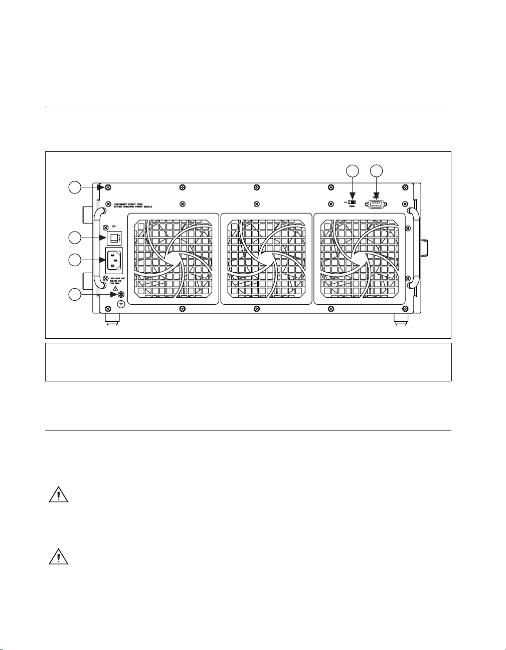
Refer to Figure 1 to locate user-accessible components on the power supply
shuttle.
6
5
AUTO
1 Chassis Ground Screw
2 Universal AC Input
3 Circuit Breaker
Figure 1. PXI-1006 Power Supply Shuttle Rear Panel
4 Mounting Screws (10x)
5 Fan Speed Selector
6 Remote Power Status and Inhibit Connector
Installation and Maintenance
The information in this section is for qualified service personnel only.
Refer to the Read Me First: Safety and Radio-Frequency Interference
document included with your kit before using the power supply shuttle.
Caution Many components within the PXI-1006 chassis under repair are susceptible to
static discharge damage. Service the chassis only in a static-free environment. Observe
standard handling precautions for static-sensitive devices while servicing the chassis.
Always wear a grounded wrist strap, or equivalent, while servicing the chassis.
Caution Always disconnect the AC power cable before cleaning or servicing the chassis.
NI PXI-1006 Power Supply Shuttle User Guide 2 ni.com
Page 3

Caution Never connect the AC power cable to the power supply shuttle until you install it
in a PXI-1006 chassis. Do not use, test, or configure the power supply shuttle outside of a
chassis.
Removal
Installation
The power supply shuttle is a replacement part for the PXI-1006 chassis.
The NI PXI-1006 User Manual contains other chassis service procedures.
The chassis includes a hardcopy of the NI PXI-1006 User Manual.
Additionally, you can download a softcopy from
Before attempting to replace the power supply shuttle, verify that there is
adequate clearance behind the chassis. Set the power switch on the front
panel to the Standby position and disconnect the power cable from the
power supply shuttle on the back of the chassis. Identify the ten mounting
screws that attach the power supply shuttle to the chassis. Refer to Figure 1
for the mounting screw locations. Using a Phillips screwdriver, loosen the
captive screws. Pull on the two rear handles of the power supply shuttle to
remove it from the back of the chassis.
Ensure that there is no visible damage to the new power supply shuttle.
Verify that the housing and connector on the new power supply shuttle
have no foreign material inside. Install the new power supply shuttle into
the opening on the rear of the chassis. Tighten the ten mounting screws with
a Phillips screwdriver.
ni.com/support.
Configuration
The fan-speed selector switch is on the rear panel of the power supply
shuttle. Refer to Figure 1 to locate the fan-speed selector switch. Select HI
for maximum cooling performance (recommended) or AUTO for quieter
operation.
© National Instruments Corporation 3 NI PXI-1006 Power Supply Shuttle User Guide
Page 4

Connecting Safety Ground
Caution The power supply shuttle is designed with a three-position NEMA 5-15 jack that
connects the ground line to the chassis ground. To minimize shock hazard, make sure the
electrical power outlet you use to power the chassis has an appropriate earth safety ground.
If your power outlet does not have an appropriate ground connection, you
must connect the premise safety ground to the chassis ground screw. Refer
to Figure 1 to locate the chassis ground screw. Complete the following
steps to connect the safety ground.
1. Connect a 16 AWG (1.3 mm) wire to the chassis ground screw using a
grounding lug. The wire must have green insulation with a yellow
stripe or must be noninsulated (bare).
2. Attach the opposite end of the wire to permanent earth ground using
toothed washers or a toothed lug.
Specifications
AC Input
Input voltage range .................................90 to 264 VAC
Input frequency range.............................47 to 63 Hz
Maximum steady state
operating current.....................................10 A
Over-current protection ..........................10 A circuit breaker
Line regulation........................................±0.1% over operating line range
Efficiency................................................70–80% typical
Power disconnect....................................The Off (standby) power switch
causes the power module to
supply DC power to
the CompactPCI/PXI backplane.
The rear-panel D-sub connector
facilitates remote inhibiting
operation. The Off (standby)
switch must be in the On position
prior to use of remote inhibit. The
power cord provides main power
disconnect.
NI PXI-1006 Power Supply Shuttle User Guide 4 ni.com
Page 5

DC Output
Maximum usable power......................... 600 W
DC current capacity (I
MP
)
Vo lt ag e IMP (Steady-State Current)
+3.3 V 60 A
+5 V 60 A
+12 V 9 A
–12 V 1.8 A
Load regulation
Vo lt ag e Regulation
+3.3 V 0.4% or 20 mV max
+12 V 0.4% or 20 mV max
+5 V 0.4% or 20 mV max
–12 V 0.4% or 20 mV max
Maximum ripple and noise .................... 1% ripple, 1% noise
20 MHz bandwidth
Over-current protection.......................... 105–140% of rated output
current; automatic recovery
Over-voltage protection ......................... 3.3 V, 5 V clamp at 122–134%
of output voltage
+12 V and –12 V clamp at
110–120% of output voltage
Power supply shuttle MTTR.................. Replacement in under 5 minutes
© National Instruments Corporation 5 NI PXI-1006 Power Supply Shuttle User Guide
 Loading...