

Page 1

INSTALLATION GUIDE
NI PS-15/16/17 Side Mount Brackets
This document provides the installation procedure for the
NI PS-15/16/17 Side Mount Brackets. This accessory is used to mount
NI PS-15/16/17 power supplies sideways to reduce the installation depth.
Two side mounting options are possible:
• 35mm DIN-Rail Mount
• Panel Mount
Bracket and Assembly Dimensions
This section provides bracket and assembly dimensions. Table 1 provides
a summary of the dimensions and weight of the overall assembly when a
specific bracket set is mounted to a specific power supply. The Unit column
lists the available power supplies. The Bracket Set column indicates the
appropriate brackets to use with the specified power supply. The A column
provides dimensions from the front of the power supply to the rearmost
mounting screw for the assembly of power supply and brackets. The
B column provides the total installation depth of the assembly when
mounted. The C column provides the depth of the power supply only.
The Length column provides the total length of the assembly. The Width
column provides the width of the mounting brackets. The Height column
provides the height of the brackets only. The Bracket Set Weight column
provides the weight of the bracket set only.
Page 2
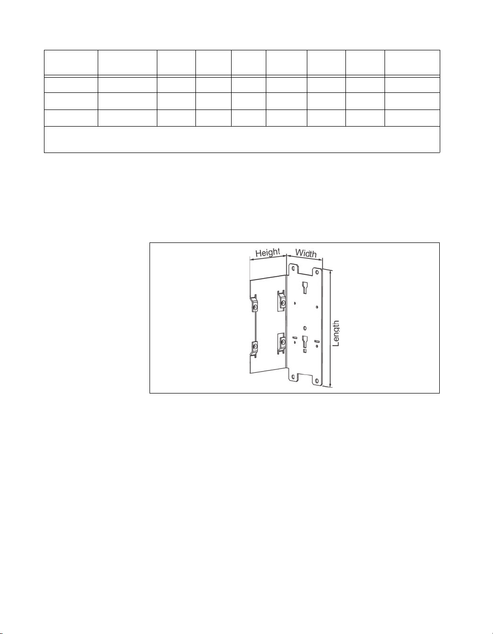
Table 1. Bracket Set and Assembly Dimensions and Weight
Use
Units
NI PS-15 199429-01 104 mm 38 mm 32 mm 145 mm 65 mm 37 mm 140 g
NI PS-16 199430-01 104 mm 66 mm 60 mm 145 mm 65 mm 63 mm 180 g
NI PS-17 199431-01 124 mm 88 mm 82 mm 145 mm 65 mm 84.5 mm 205 g
1
If the unit is panel mounted, the B dimension shows the required installation depth. If the unit is DIN-Rail mounted, the
total installation depth is the B dimension plus 6mm plus the height of the DIN-Rail.
Bracket Set
A B
1
C Length Width Height
Bracket Set
Wei ght
Figure 1, Figure 2, and Figure 3 show the brackets for DIN-Rail mounting.
Figure 1 provides the layout of a mounting bracket in three physical
dimensions, to allow easier visualization when using Table 1 with Figure 2
and Figure 3 to determine the dimensions of a specified bracket set
mounted to a specified power supply.
Figure 1. Physical Dimension Variables
Figure 2 provides the B and C variables for determining the depth of a
bracketed power supply assembly when mounting the assembly to a
DIN-Rail or panel.
The total installation depth is the B dimension plus 6mm plus the height of
the DIN-Rail. In case the unit is panel mounted, the B dimension shows the
required installation depth. The C dimension is the depth of the power
supply itself, and its sum is included in the value of B. All measurements
are in millimeters.
NI PS-15/16/17 Side Mount Brackets Installation Guide 2 ni.com
Page 3
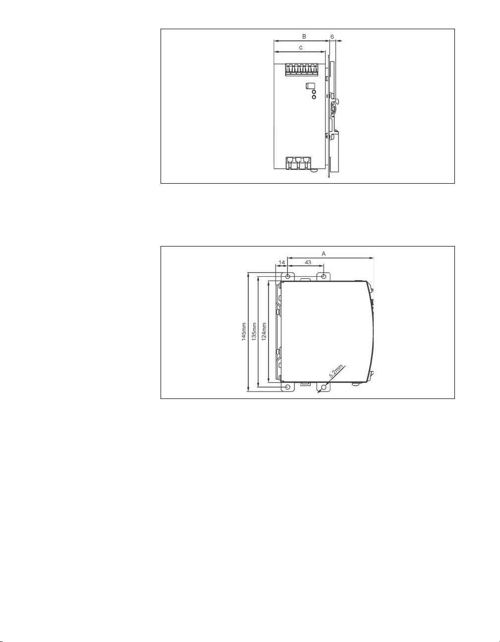
Figure 2. Calculating the Installation Depth of the Assembly
Figure 3 provides the constants and variables for determining the length
and depth of a bracketed power supply mounted to a DIN-Rail.
Figure 3. Calculating the Dimensions for Screw Mounts
© National Instruments Corporation 3 NI PS-15/16/17 Side Mount Brackets Installation Guide
Page 4

Assembly and Mounting Instructions
This section provides instructions for mounting the power supply sideways
to a panel or to a DIN-Rail.
Note The two aluminum brackets and the black plastic slide must be removed from the
units to allow mounting of the zinc-plated steel brackets.
Sideways Panel Mounting
Complete the following steps to mount the brackets to a flat wall.
1. Detach the two aluminium brackets by removing the four screws with
a Torx 10 screwdriver, as shown in Figure 4.
Figure 4. Removing the Aluminum Brackets
2. Remove the plastic lock mechanism with a flathead screwdriver to
move the lock downward while at the same time pushing the plastic
slider upwards. Detach the plastic slider, as shown in Figure 5.
NI PS-15/16/17 Side Mount Brackets Installation Guide 4 ni.com
Page 5

Figure 5. Removing the Plastic Slider
Caution
Do not over-tighten the screws. The recommended tightening torque is
0.6 Nm/5.3 lb. in.
3. Mount the steel brackets with the same screws from the DIN-Rail
brackets as shown in Figure 6.
Figure 6. Mounting the Steel Brackets
© National Instruments Corporation 5 NI PS-15/16/17 Side Mount Brackets Installation Guide
Page 6

DIN-Rail Mounting
Complete the following steps to mount the brackets to a DIN-Rail.
1. Install the mounting plate with the steps described in the Sideways
Panel Mounting section. When those steps are completed, the
mounting plate should be attached to the power supply as shown
in Figure 7.
Figure 7. Installing the Mounting Brackets
2. Attach the two aluminum brackets and the plastic slider to the side
mounting plate, as shown in Figure 8. The additional required screws
are included in the shipping box.
Figure 8. Installing the Aluminum Brackets and Plastic Slider
NI PS-15/16/17 Side Mount Brackets Installation Guide 6 ni.com
Page 7

Where to Go for Support
The National Instruments Web site is your complete resource for technical
support. At
troubleshooting and application development self-help resources to email
and phone assistance from NI Application Engineers.
National Instruments corporate headquarters is located at
11500 North Mopac Expressway, Austin, Texas, 78759-3504.
National Instruments also has offices located around the world to help
address your support needs. For telephone support in the United States,
create your service request at
instructions or dial 512 795 8248. For telephone support outside the United
States, contact your local branch office:
Australia 1800 300 800, Austria 43 662 457990-0,
Belgium 32 (0) 2 757 0020, Brazil 55 11 3262 3599,
Canada 800 433 3488, China 86 21 5050 9800,
Czech Republic 420 224 235 774, Denmark 45 45 76 26 00,
Finland 358 (0) 9 725 72511, France 01 57 66 24 24,
Germany 49 89 7413130, India 91 80 41190000, Israel 972 3 6393737,
Italy 39 02 41309277, Japan 0120-527196, Korea 82 02 3451 3400,
Lebanon 961 (0) 1 33 28 28, Malaysia 1800 887710,
Mexico 01 800 010 0793, Netherlands 31 (0) 348 433 466,
New Zealand 0800 553 322, Norway 47 (0) 66 90 76 60,
Poland 48 22 328 90 10, Portugal 351 210 311 210,
Russia 7 495 783 6851, Singapore 1800 226 5886,
Slovenia 386 3 425 42 00, South Africa 27 0 11 805 8197,
Spain 34 91 640 0085, Sweden 46 (0) 8 587 895 00,
Switzerland 41 56 2005151, Taiwan 886 02 2377 2222,
Thailand 662 278 6777, Turkey 90 212 279 3031,
United Kingdom 44 (0) 1635 523545
ni.com/support you have access to everything from
ni.com/support and follow the calling
© National Instruments Corporation 7 NI PS-15/16/17 Side Mount Brackets Installation Guide
Page 8

National Instruments, NI, ni.com, and LabVIEW are trademarks of National Instruments Corporation.
Refer to the Terms of Use section on ni.com/legal for more information about National
Instruments trademarks. Other product and company names mentioned herein are trademarks or trad e
names of their respective companies. For patents covering National Instruments products/technology,
refer to the appropriate location: Help»Patents in your software, the patents.txt file on your
media, or the National Instruments Patent Notice at ni.com/patents.
© 2009 National Instruments Corporation. All rights reserved.
372908A-01 Jul09
 Loading...