

Page 1

GETTING STARTED GUIDE
NI PCIe-7821R
R Series Digital I/O Module for PCI Express, 128 DIO, 512 MB DRAM,
Kintex-7 160T FPGA
This document describes how to begin using the PCIe-7821R.
Safety Guidelines
Caution Do not operate the PCIe-7821R in a manner not specified in this
document. Product misuse can result in a hazard. You can compromise the safety
protection built into the product if the product is damaged in any way. If the product
is damaged, return it to NI for repair.
Electromagnetic Compatibility Guidelines
This product was tested and complies with the regulatory requirements and limits for
electromagnetic compatibility (EMC) stated in the product specifications. These requirements
and limits provide reasonable protection against harmful interference when the product is
operated in the intended operational electromagnetic environment.
Page 2

This product is intended for use in industrial locations. However, harmful interference may
occur in some installations, when the product is connected to a peripheral device or test object,
or if the product is used in residential or commercial areas. To minimize interference with
radio and television reception and prevent unacceptable performance degradation, install and
use this product in strict accordance with the instructions in the product documentation.
Furthermore, any changes or modifications to the product not expressly approved by National
Instruments could void your authority to operate it under your local regulatory rules.
Caution To ensure the specified EMC performance, operate this product only with
shielded cables and accessories.
Caution To ensure the specified EMC performance, the length of all I/O cables
must be no longer than 3 m (10 ft).
Preparing the Environment
Ensure that the environment in which you are using the PCIe-7821R meets the following
specifications.
Operating temperature
(IEC 60068-2-1, IEC 60068-2-2)
0 °C to 40 °C
Operating humidity (IEC 60068-2-56) 10% RH to 90% RH, noncondensing
Pollution degree 2
Maximum altitude 2,000 m
Indoor use only.
Note Refer to the device specifications on ni.com/manuals for complete
specifications.
Unpacking the Kit
Caution To prevent electrostatic discharge (ESD) from damaging the device,
ground yourself using a grounding strap or by holding a grounded object, such as
your computer chassis.
1. Touch the antistatic package to a metal part of the computer chassis.
2. Remove the device from the package and inspect the device for loose components or any
other sign of damage.
Caution Never touch the exposed pins of connectors.
Note Do not install a device if it appears damaged in any way.
2 | ni.com | NI PCIe-7821R Getting Started Guide
Page 3
3. Unpack any other items and documentation from the kit.
Store the device in the antistatic package when the device is not in use.
Verifying the Kit Contents
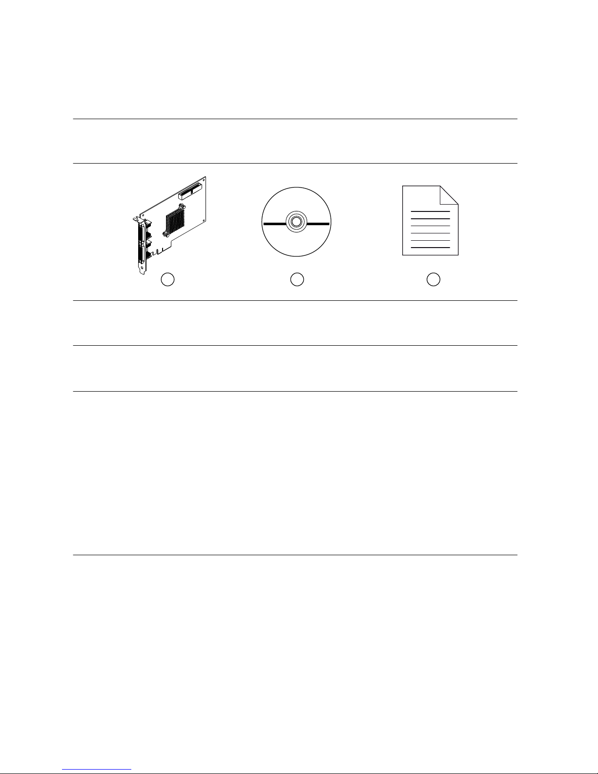
Verify that the following items are included in the PCIe-7821R kit.
Figure 1. PCIe-7821R Kit Contents
3
2
1
1. Hardware
2. NI-RIO Media
3. Getting Started Guide
Installing Software on the Host Computer
Before using the PCIe-7821R, you must install the following application software and device
drivers on the host computer.
1. LabVIEW 2017 or later
2. LabVIEW FPGA Module 2017 or later
3. NI R Series Multifunction RIO Device Drivers May 2017 or later
Visit ni.com/info and enter the Info Code softwareversion for minimum software support
information.
Installing the PCIe-7821R
1. Power off and unplug the computer.
2. Access the computer system expansion slots. This step might require you to remove one
or more access panels on the computer case.
3. Locate a compatible slot and remove the corresponding slot cover on the computer back
panel.
4. Touch any metal part of the computer to discharge any static electricity.
5. Insert the PCIe-7821R into the applicable PCI Express system slot. Gently rock the
PCIe-7821R into place. Do not force the device into place.
NI PCIe-7821R Getting Started Guide | © National Instruments | 3
Page 4

You cannot install PCI Express devices in PCI slots. PCI Express devices support upplugging into a PCI Express slot of higher lane width. For more information, refer to
ni.com/pciexpress.
Figure 2. Installing a PCI Express Device
1
3
2
1. PCI Express Device
2. PCI Express System Slot
3. PC with PCI Express Slot
6. Secure the module mounting bracket to the computer back panel rail.
7. Replace any access panels on the computer case.
8. Plug in and power on your computer.
9. If applicable, install accessories and/or terminal blocks as described in the installation
guides.
10. Attach sensors and signal lines to the device, terminal block, or accessory terminals.
Verifying Hardware Installation
You can verify that the system recognizes the PCIe-7821R by using Measurement &
Automation Explorer (MAX).
1. Launch MAX by navigating to Start»All Programs»National Instruments»MAX or by
clicking the MAX desktop icon.
2. Expand Devices and Interfaces.
3. Verify that the device appears under Devices and Interfaces.
If the device does not appear, press <F5> to refresh the view in MAX. If the device does
not appear after refreshing the view, visit ni.com/support for troubleshooting information.
4 | ni.com | NI PCIe-7821R Getting Started Guide
Page 5

Pinout
DIO30
GND
DIO28
GND
DIO26
GND
DIO24
GND
DIO22
GND
DIO20
GND
DIO18
GND
DIO16
GND
DIO14
GND
DIO12
GND
DIO10
GND
DIO8
GND
DIO6
GND
DIO4
GND
DIO2
GND
DIO0
GND
EXTCLKIN x
GND
DIO31
DIO29
GND
GND
DIO25
GND
DIO23
GND
DIO27
GND
DIO21
GND
DIO19
GND
DIO17
GND
DIO15
GND
DIO13
GND
DIO11
GND
DIO9
GND
DIO7
GND
DIO5
GND
DIO3
GND
DIO1
GND
GND
GND
68 34
67 33
66 32
65 31
64 30
63 29
62 28
61 27
60 26
59 25
58 24
57 23
56 22
55 21
54 20
53 19
52 18
51 17
50 16
49 15
48 14
47 13
46 12
45 11
44 10
43 9
42 8
41 7
40 6
39 5
38 4
37 3
36 2
35 1
*x is the connector number.
EXTCLKIN x is an input only.
Table 1. PCIe-7821R Signal Descriptions
Signal Description
DIO Digital input/output signal connection
EXTCLKIN External clock input source that can be used for source synchronous
acquisitions. The provided clock source must be stable and glitch-free.
GND Ground connection
The PCIe-7821R is protected from overvoltage and overcurrent conditions.
Note Refer to the device specifications, available at ni.com/manuals for more
information.
NI PCIe-7821R Getting Started Guide | © National Instruments | 5
Page 6

Digital I/O Connections
Figure 3. Connecting to the DIO Channels
NI PCIe-7821R
Power
FPGA
Connection
Accessory
DIO0
DIO1
DIO30
DIO31
Connector X (DIO)
1
2
1. High-speed signal frequencies up to 80 MHz with logic levels configured as 1.2 V, 1.5 V, 1.8 V, 2.5 V, or
3.3 V
2. LED
The DIO channels connect to the FPGA through protection circuitry, which has overvoltage
and undervoltage protection as well as overcurrent protection.
Note Refer to the device specifications, available at ni.com/manuals for more
information.
When the system powers on, the DIO channels are set as input low with pull-down resistors.
To set another power-on state, you can configure the PCIe-7821R to load a VI when the
system powers on. The VI can then set the DIO lines to any power-on state. Visit ni.com/info
and enter RSeries_PowerUpStates to learn more about configuring the power-up states
for the PCIe-7821R.
All the DIO channels on Connectors 0 through 3 are routed with a 50 Ω characteristic trace
impedance. Route all external circuitry with a similar impedance to ensure best signal quality.
NI recommends performing signal integrity measurements to test the affect of signal routing
with the cable and connection accessory for your application.
Installing Noise Suppression Ferrites
For each connected I/O cable, install two (2) snap-on, ferrite beads (777297-01), one on each
end of the cable, as close to the connector as practical.
6 | ni.com | NI PCIe-7821R Getting Started Guide
Page 7

Figure 4. Ferrite Installation
1
2
1. I/O cable
2. Ferrites
Two (2) snap-on, ferrite beads (777297-01) are included in each of the following
recommended cable kits:
• Shielded R Series High Speed Digital Cable, 1m (156166-01)
• Shielded R Series High Speed Digital Cable, 2m (156166-02)
For user-supplied cables, visit ni.com/info and enter RDIO2FERRITE for ferrite beads that can
be ordered directly from NI.
NI PCIe-7821R Getting Started Guide | © National Instruments | 7
Page 8

Where to Go Next
SUPPORT
Services
ni.com/services
NI Community
ni.com/community
Software Support
ni.com/info>swsupport
Support
ni.com/support
SOFTWAREHARDWARE
Configuring a Project
NI-RIO Help
Learn LabVIEW Basics
ni.com/gettingstarted
NI R Series Examples
NI Example Finder
NI PCIe-7820R Specifications
ni.com/manuals
NI PCIe-7820R User Manual
ni.com/manuals
Worldwide Support and Services
The NI website is your complete resource for technical support. At ni.com/support, you have
access to everything from troubleshooting and application development self-help resources to
email and phone assistance from NI Application Engineers.
Visit ni.com/services for NI Factory Installation Services, repairs, extended warranty, and
other services.
Visit ni.com/register to register your NI product. Product registration facilitates technical
support and ensures that you receive important information updates from NI.
A Declaration of Conformity (DoC) is our claim of compliance with the Council of the
European Communities using the manufacturer’s declaration of conformity. This system
affords the user protection for electromagnetic compatibility (EMC) and product safety. You
can obtain the DoC for your product by visiting ni.com/certification. If your product supports
calibration, you can obtain the calibration certificate for your product at ni.com/calibration.
8 | ni.com | NI PCIe-7821R Getting Started Guide
Page 9

NI corporate headquarters is located at 11500 North Mopac Expressway, Austin, Texas,
78759-3504. NI also has offices located around the world. For telephone support in the United
States, create your service request at ni.com/support or dial 1 866 ASK MYNI (275 6964). For
telephone support outside the United States, visit the Worldwide Offices section of ni.com/
niglobal to access the branch office websites, which provide up-to-date contact information,
support phone numbers, email addresses, and current events.
NI PCIe-7821R Getting Started Guide | © National Instruments | 9
Page 10

Information is subject to change without notice. Refer to the NI Trademarks and Logo Guidelines at ni.com/trademarks for
information on NI trademarks. Other product and company names mentioned herein are trademarks or trade names of their
respective companies. For patents covering NI products/technology, refer to the appropriate location: Help»Patents in your
software, the patents.txt file on your media, or the National Instruments Patent Notice at ni.com/patents. You can find
information about end-user license agreements (EULAs) and third-party legal notices in the readme file for your NI product. Refer
to the Export Compliance Information at ni.com/legal/export-compliance for the NI global trade compliance policy and how
to obtain relevant HTS codes, ECCNs, and other import/export data. NI MAKES NO EXPRESS OR IMPLIED WARRANTIES AS
TO THE ACCURACY OF THE INFORMATION CONTAINED HEREIN AND SHALL NOT BE LIABLE FOR ANY ERRORS. U.S.
Government Customers: The data contained in this manual was developed at private expense and is subject to the applicable
limited rights and restricted data rights as set forth in FAR 52.227-14, DFAR 252.227-7014, and DFAR 252.227-7015.
© 2017 National Instruments. All rights reserved.
376830A-01 Apr17
 Loading...