

Page 1

™
IMAQ
NI-IMAQ™for IEEE-1394 Cameras User Manual
Image Acquisition Software
NI-IMAQ for IEEE-1394 Cameras User Manual
March 2001 Edition
Part Number 370362A-01
Page 2

Worldwide Technical Support and Product Information
ni.com
National Instruments Corporate Headquarters
11500 North Mopac Expressway Austin, Texas 78759-3504 USA Tel: 512 794 0100
Worldwide Offices
Australia 03 9879 5166, Austria 0662 45 79 90 0, Belgium 02 757 00 20, Brazil 011 284 5011,
Canada (Calgary) 403 274 9391, Canada (Ottawa) 613 233 5949, Canada (Québec) 514 694 8521,
Canada (Toronto) 905 785 0085, China (Shanghai) 021 6555 7838, China (ShenZhen) 0755 3904939,
Denmark 45 76 26 00, Finland 09 725 725 11, France 01 48 14 24 24, Germany 089 741 31 30,
Greece 30 1 42 96 427, Hong Kong 2645 3186, India 91805275406, Israel 03 6120092, Italy 02 413091,
Japan 03 5472 2970, Korea 02 596 7456, Mexico 5 280 7625, Netherlands 0348 433466,
New Zealand 09 914 0488, Norway 32 27 73 00, Poland 0 22 528 94 06, Portugal 351 1 726 9011,
Singapore 2265886, Spain 91 640 0085, Sweden 08 587 895 00, Switzerland 056 200 51 51,
Taiwan 02 2528 7227, United Kingdom 01635 523545
For further support information, see the Technical Support Resources appendix. To comment on the
documentation, send e-mail to techpubs@ni.com
Copyright © 2001 National Instruments Corporation. All rights reserved.
Page 3

Important Information
Warranty
The media on which you receive National Instruments software are warranted not to fail to execute programming instructions, due to defects
in materials and workmanship, for a period of 90 days from date of shipment, as evidenced by receipts or other documentation. National
Instruments will, at its option, repair or replace software media that do not execute programming instructions if National Instruments receives
notice of such defects during the warranty period. National Instruments does not warrant that the operation of the software shall be
uninterrupted or error free.
A Return Material Authorization (RMA) number must be obtained from the factory and clearly marked on the outside of the package before
any equipment will be accepted for warranty work. National Instruments will pay the shipping costs of returning to the owner parts which are
covered by warranty.
National Instruments believes that the information in this document is accurate. The document has been carefully reviewed for technical
accuracy. In the event that technical or typographical errors exist, National Instruments reserves the right to make changes to subsequent
editions of this document without prior notice to holders of this edition. The reader should consult National Instruments if errors are suspected.
In no event shall National Instruments be liable for any damages arising out of or related to this document or the information contained in it.
XCEPT AS SPECIFIED HEREIN,NATIONAL INSTRUMENTS MAKES NO WARRANTIES, EXPRESS OR IMPLIED, AND SPECIFICALLY DISCLAIMS ANY WARRANTY OF
E
MERCHANTABILITY OR FITNESS FOR A PARTICULAR PURPOSE
NATIONAL INSTRUMENTS SHALL BE LIMITED TO THE AMOUNT THERETOFORE PAID B Y THE CUSTOMER.NATIONAL INSTRUMENTS WILL NOT BE LIABLE FOR
DAMAGES RESULTING FROM LOSS OF DATA
. This limitation of the liability of NationalInstruments will apply regardless ofthe form of action,whether in contract or tort, including
THEREOF
negligence. Any action against National Instruments must be brought within one year after the cause of action accrues. National Instruments
shall not be liable for any delay in performance due to causes beyond its reasonable control. The warranty provided herein does not cover
damages, defects, malfunctions, or service failures caused by owner’s failure to follow the National Instruments installation, operation, or
maintenance instructions; owner’s modification of the product; owner’s abuse, misuse, or negligent acts; and power failure or surges, fire,
flood, accident, actions of third parties, or other events outside reasonable control.
, PROFITS, USE OF PRODUCTS, OR INCIDENTAL OR CONSEQUENTIAL DAMAGES, EVEN IF ADVISED OF THE POSSIBILITY
Copyright
Under the copyright laws, this publication may not be reproduced ortransmitted in any form, electronic or mechanical, including photocopying,
recording, storing in an information retrieval system, or translating, in whole or in part, without the prior written consent of National
Instruments Corporation.
Trademarks
IMAQ™,LabVIEW™, National Instruments™,ni.com™, and NI-IMAQ™are trademarks of National Instruments Corporation.
Product and company names mentioned herein are trademarks or trade names of their respective companies.
.CUSTOMER’S RIGHT TO RECOVER DAMAGES CAUSED BY FAULT OR NEGLIGENCE ON THE PART OF
WARNING REGARDING USE OF NATIONAL INSTRUMENTS PRODUCTS
(1) NATIONAL INSTRUMENTS PRODUCTS ARE NOT DESIGNED WITH COMPONENTS AND TESTING FOR A LEVEL OF
RELIABILITY SUITABLE FOR USE IN OR IN CONNECTION WITH SURGICAL IMPLANTS OR AS CRITICAL COMPONENTS IN
ANY LIFE SUPPORT SYSTEMS WHOSE FAILURE TO PERFORM CAN REASONABLY BE EXPECTED TO CAUSE SIGNIFICANT
INJURY TO A HUMAN.
(2) IN ANY APPLICATION, INCLUDING THE ABOVE, RELIABILITY OF OPERATION OF THE SOFTWARE PRODUCTS CAN BE
IMPAIRED BY ADVERSE FACTORS, INCLUDING BUT NOT LIMITED TO FLUCTUATIONS IN ELECTRICAL POWER SUPPLY,
COMPUTER HARDWARE MALFUNCTIONS, COMPUTER OPERATING SYSTEM SOFTWARE FITNESS, FITNESS OF COMPILERS
AND DEVELOPMENT SOFTWARE USED TO DEVELOP AN APPLICATION, INSTALLATION ERRORS, SOFTWARE AND
HARDWARE COMPATIBILITY PROBLEMS, MALFUNCTIONS OR FAILURES OF ELECTRONIC MONITORING OR CONTROL
DEVICES, TRANSIENT FAILURES OF ELECTRONIC SYSTEMS (HARDWARE AND/OR SOFTWARE), UNANTICIPATED USES OR
MISUSES, OR ERRORS ON THE PART OF THE USER OR APPLICATIONS DESIGNER (ADVERSE FACTORS SUCH AS THESE ARE
HEREAFTER COLLECTIVELY TERMED “SYSTEM FAILURES”). ANY APPLICATION WHERE A SYSTEM FAILURE WOULD
CREATE A RISK OF HARM TO PROPERTY OR PERSONS (INCLUDING THE RISK OF BODILY INJURY AND DEATH) SHOULD
NOT BE RELIANT SOLELY UPON ONE FORM OF ELECTRONIC SYSTEM DUE TO THE RISK OF SYSTEM FAILURE. TO AVOID
DAMAGE, INJURY, OR DEATH, THE USER OR APPLICATION DESIGNER MUST TAKE REASONABLY PRUDENT STEPS TO
PROTECT AGAINST SYSTEM FAILURES, INCLUDING BUT NOT LIMITED TO BACK-UP OR SHUT DOWN MECHANISMS.
BECAUSE EACH END-USER SYSTEM IS CUSTOMIZED AND DIFFERS FROM NATIONAL INSTRUMENTS' TESTING
PLATFORMS AND BECAUSE A USER OR APPLICATION DESIGNER MAY USE NATIONAL INSTRUMENTS PRODUCTS IN
COMBINATION WITH OTHER PRODUCTS IN A MANNER NOT EVALUATED OR CONTEMPLATED BY NATIONAL
INSTRUMENTS, THE USER OR APPLICATION DESIGNER IS ULTIMATELY RESPONSIBLE FOR VERIFYING AND VALIDATING
THE SUITABILITY OF NATIONAL INSTRUMENTS PRODUCTS WHENEVER NATIONAL INSTRUMENTS PRODUCTS ARE
INCORPORATED IN A SYSTEM OR APPLICATION, INCLUDING, WITHOUT LIMITATION, THE APPROPRIATE DESIGN,
PROCESS AND SAFETY LEVEL OF SUCH SYSTEM OR APPLICATION.
Page 4

Conventions
The following conventions are used in this manual:
» The » symbol leads you through nested menu items and dialog box options
to a final action. The sequence File»Page Setup»Options directs you to
pull down the File menu, select the Page Setup item, and select Options
from the last dialog box.
This icon denotes a note, which alerts you to important information.
bold Bold text denotes items that you must select or click on in the software,
such as menu items and dialog box options. Bold text also denotes
parameter names.
italic Italic text denotes variables, emphasis, a cross reference, or an introduction
to a key concept. This font also denotes text that is a placeholder for a word
or value that you must supply.
monospace
monospace italic
NI-IMAQ for 1394 NI-IMAQ for 1394 represents the NI-IMAQ for IEEE-1394 Cameras
Text in this font denotes text or characters that you should enter from the
keyboard, sections of code, programming examples, and syntax examples.
This font is also used for the proper names of disk drives, paths, directories,
programs, subprograms, subroutines, device names, functions, operations,
variables, filenames and extensions, and code excerpts.
Italic text in this font denotes text that is a placeholder for a word or value
that you must supply.
software package.
Page 5

Contents
Chapter 1
Introduction to NI-IMAQ for IEEE-1394 Cameras
About the NI-IMAQ Software....................................................................................... 1-1
Application Development Environments ........................................................1-2
Configuring Your IEEE-1394 Camera............................................................1-2
Fundamentals of Building Applications with NI-IMAQ for 1394 ................................1-3
Architecture .....................................................................................................1-3
The NI-IMAQ Libraries ..................................................................................1-4
Creating an Application...................................................................................1-4
Sample Programs.............................................................................................1-5
Chapter 2
Software Overview
Introduction....................................................................................................................2-1
Generic Functions ..........................................................................................................2-1
High-Level Functions ....................................................................................................2-2
Snap Functions ................................................................................................2-2
Grab Functions ................................................................................................2-2
Sequence Functions .........................................................................................2-3
Trigger Functions ............................................................................................2-3
Miscellaneous Functions .................................................................................2-3
Low-Level Functions.....................................................................................................2-3
Acquisition Functions......................................................................................2-3
Attribute Functions..........................................................................................2-4
Utility Functions..............................................................................................2-5
Chapter 3
Programming with NI-IMAQ for 1394
Introduction....................................................................................................................3-1
High-Level Functions......................................................................................3-1
Low-Level Functions....................................................................................... 3-2
Establishing Interface Connections ...............................................................................3-2
Camera Functions............................................................................................3-2
Camera Attributes .......................................................................................................... 3-3
Scalable Image Size ....................................................................................................... 3-4
© National Instruments Corporation v NI-IMAQ for IEEE-1394 Cameras User Manual
Page 6

Contents
Introductory Programming Examples ........................................................................... 3-5
High-Level Snap Functions ............................................................................ 3-5
High-Level Grab Functions ............................................................................ 3-6
High-Level Sequence Functions ..................................................................... 3-8
Advanced Programming Examples ............................................................................... 3-9
Performing a Snap Using Low-Level Functions............................................. 3-9
Performing a Grab Using Low-Level Functions............................................. 3-9
Performing a Sequence Acquisition Using Low-Level Functions.................. 3-9
Performing an Asynchronous Snap Using Low-Level Functions .................. 3-10
Performing an Asynchronous Grab using Low-Level Functions ................... 3-10
Chapter 4
Programming with NI-IMAQ for 1394 VIs
Introduction ................................................................................................................... 4-1
Location of NI-IMAQ for 1394 Examples....................................................................4-2
Location of the NI-IMAQ for 1394 VIs........................................................................ 4-2
Common NI-IMAQ for 1394 VI Parameters ................................................................ 4-3
Buffer Management....................................................................................................... 4-4
NI-IMAQ for 1394 Acquisition Types.......................................................................... 4-5
Snap................................................................................................................. 4-5
Grab................................................................................................................. 4-5
Sequence ......................................................................................................... 4-6
Acquisition VIs.............................................................................................................. 4-7
High-Level ...................................................................................................... 4-7
Low-Level....................................................................................................... 4-7
Triggering ......................................................................................................................4-8
Image Display................................................................................................................ 4-8
Camera Attributes..........................................................................................................4-11
Error Handling............................................................................................................... 4-12
Error Code Format......................................................................................................... 4-13
Appendix A
Technical Support Resources
Glossary
Index
NI-IMAQ for IEEE-1394 Cameras User Manual vi ni.com
Page 7

Introduction to NI-IMAQ for
IEEE-1394 Cameras
This chapter describes the NI-IMAQ for IEEE-1394 software and lists the
application development environments compatible with NI-IMAQ,
describes the fundamentals of creating NI-IMAQ applications for
Windows 2000 and Windows Me/98, describes the files used to build these
applications, and tells you where to find sample programs.
About the NI-IMAQ Software
NI-IMAQ for 1394 gives you the ability to use industrial digital video
cameras with the NI-IMAQ driver software and IMAQ Vision. You can use
cameras with the following output formats:
• Monochrome (8 bits/pixel)
• Monochrome (16 bits/pixel)
• RGB (24 bits/pixel)
• YUV 4:1:1 (12 bits/pixel)
• YUV 4:2:2 (16 bits/pixel)
• YUV 4:4:4 (24 bits/pixel)
1
The cameras may operate at various resolutions and frame rates, depending
on camera capabilities.
NI-IMAQ for 1394 uses a WDM driver to directly access the 1394
interface, so that NI-IMAQ can control all of the available modes of the
digital camera.
© National Instruments Corporation 1-1 NI-IMAQ for IEEE-1394 Cameras User Manual
Page 8

Chapter 1 Introduction to NI-IMAQ for IEEE-1394 Cameras
Application Development Environments
This release of NI-IMAQ for 1394 supports the following Application
Development Environments (ADEs) for Windows 2000 and
Windows Me/98:
• LabVIEW version 5.1 and higher
• LabWindows/CVI version 5.0 and higher
• Borland C++ Builder 3.0 and higher
• Microsoft Visual C/C++ version 6.0 and higher
Note
Although NI-IMAQ for 1394 has been tested and found to work with these ADEs,
other ADEs may also work.
Configuring Your IEEE-1394 Camera
You can use National Instruments Measurement & Automation Explorer
(MAX) to configure your IEEE-1394 camera.
Set your camera’s properties by right-clicking on your camera in the IMAQ
IEEE-1394 Devices folder in the MAX configuration tree. Select
Properties from the pop-up menu. Adjust your camera’sattributesand
click OK to save the camera file.
The camera information is saved in a camera file, which the LabVIEW VIs
use to select a camera and its supported attributes.
NI-IMAQ for IEEE-1394 Cameras User Manual 1-2 ni.com
Page 9
Chapter 1 Introduction to NI-IMAQ for IEEE-1394 Cameras
Fundamentals of Building Applications with
NI-IMAQ for 1394
Architecture
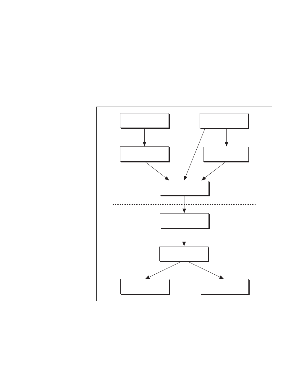
A block diagram of the NI-IMAQ for 1394 architecture shown in
Figure 1-1 illustrates the low- and mid-level architecture for IMAQ
devices.
LabVIEW
IMAQ Vision
Application Level
Kernel
OCHI1394.SYS
LabWindows/CVI
Visual C++/Borland
IMAQ Vision
IMAQ1394.DLL
IMAQ1394.SYS
1394BUS.SYS
TILYNX.SYS
Figure 1-1. NI-IMAQ for 1394 Architecture
© National Instruments Corporation 1-3 NI-IMAQ for IEEE-1394 Cameras User Manual
Page 10

Chapter 1 Introduction to NI-IMAQ for IEEE-1394 Cameras
The NI-IMAQ Libraries
The NI-IMAQ for 1394 for Windows 2000/Me/98 function libraries are
dynamic link libraries (DLLs), which means that NI-IMAQ for 1394
routines are not linked into the executable files of applications. Only the
information about the NI-IMAQ routines in the NI-IMAQ import libraries
is stored in the executable files.
Import libraries contain information about their DLL-exported functions.
They indicate the presence and location of the DLL routines. Depending
on the development tools you are using, you may give the DLL routines
information through import libraries or through function declarations.
Your NI-IMAQ for 1394 software kit contains function prototypes for all
routines.
Creating an Application
This section outlines the process for developing NI-IMAQ for 1394
applications using C for Windows 2000/Me/98. Detailed instructions on
creating project and source files are not included. For information on
creating and managing project files, consult the documentation included
with your particular development environment.
When programming, use the following guidelines:
• Include the
NI-IMAQ functions. Add this file to the top of your source files.
• Add the
environments allow you to add import libraries simply by inserting
them into your list of project files. Other environments allow you
to specify import libraries under the linker settings portion of the
project file.
NI-IMAQ for IEEE-1394 Cameras User Manual 1-4 ni.com
niimaq1394.h
niimaq1394.lib
header file in all C source files that use
import library to your project. Some
Page 11

Chapter 1 Introduction to NI-IMAQ for IEEE-1394 Cameras
• When compiling, indicate where the compiler can find the NI-IMAQ
header files and shared libraries. You can find most of the files you
need for development under the NI-IMAQ target installation directory.
If you choose the default directory during installation, the target
installation directory is
Instruments\NI-IMAQ for IEEE-1394
files under the
under the
include
lib\<environment>
C:\Program Files\National
. You can find the include
subdirectory. The import libraries are located
subdirectory for the following
platforms.
Sample Programs
Table 1-1.
Import Libraries
Development Environment Directory
Microsoft Visual C++
Borland C++
Please refer to the
readme.txt
file located in your target installation
lib\msvc
lib\borland
directory for the latest details on NI-IMAQ for 1394 sample programs.
These programs are installed in the
sample
subdirectory under the target
installation folder, if you elected to install the sample files.
© National Instruments Corporation 1-5 NI-IMAQ for IEEE-1394 Cameras User Manual
Page 12

Software Overview
This chapter describes the classes of NI-IMAQ for 1394 functions and
briefly describes each function.
Introduction
NI-IMAQ functions are grouped according to the following classes:
• Generic functions
• High-level functions
– Snap functions
– Grab functions
– Sequence functions
– Trigger functions
• Low-level functions
– Acquisition functions
– Attribute functions
– Utility functions
2
The generic and high-level functions appear within each function class in
the logical order you might need to use them. The low-level functions
appear within each function class in alphabetical order.
Generic Functions
Use generic functions in both high-level and low-level applications.
imaq1394CameraOpen
imaq1394Close
© National Instruments Corporation 2-1 NI-IMAQ for IEEE-1394 Cameras User Manual
Opens a session on a camera by
name.
Closes a session and unlocks and
releases all buffers.
Page 13

Chapter 2 Software Overview
High-Level Functions
Use high-level functions to quickly and easily capture images. If you need
more advanced functionality, you can mix high-level functions with
low-level functions.
Snap Functions
Snap functions capture all or a portion of a single frame or field to the user
buffer.
Grab Functions
imaq1394SnapImage
imaq1394Snap
Grab functions start a continuous image acquisition to a user buffer. Any
frame or field can be copied from the grab buffer to another user buffer.
imaq1394SetupGrab
imaq1394GrabImage
imaq1394Grab
Performs a single frame
acquisition in an image buffer,
which is allocated using IMAQ
Vision memory management.
Performs a single frame
acquisition in a memory buffer,
which is allocated without using
IMAQ Vision memory
management.
Configures and starts a continuous
acquisition.
Acquires the most current frame
into the specified IMAQ Vision
image buffer. Call this function
only after calling
imaq1394SetupGrab
Acquires the most current frame
into a previously allocated buffer.
Call this function only after calling
imaq1394SetupGrab
.
.
NI-IMAQ for IEEE-1394 Cameras User Manual 2-2 ni.com
Page 14

Sequence Functions
Chapter 2 Software Overview
Sequence functions start and stop a continuous acquisition of multiple
frames.
imaq1394SetupSequenceImage
imaq1394SetupSequence
Trigger Functions
Trigger functions control the trigger mode of the IEEE-1394 camera.
imaq1394TriggerConfigure
Miscellaneous Functions
Miscellaneous functions return information such as session status.
imaq1394Status
Low-Level Functions
Use low-level functions when you require more direct control of the
acquisition of the images.
Configures and starts a session for
acquiring a full sequence into the
list of buffers managed by
IMAQ Vision.
Configures and starts a session for
acquiring a full sequence in the
buffer list.
Configures an acquisition to start
based on an external trigger.
Gets the current session status.
Acquisition Functions
Use acquisition functions to configure, start, and abort an image
acquisition, or examine a buffer during an acquisition.
imaq1394ConfigureAcquisition
imaq1394StartAcquisition
© National Instruments Corporation 2-3 NI-IMAQ for IEEE-1394 Cameras User Manual
Configures the acquisition
session mode (continuous or
one-shot).
Starts acquisition synchronously
or asynchronously.
Page 15

Chapter 2 Software Overview
Attribute Functions
imaq1394StopAcquisition
Stops an asynchronous acquisition
or synchronous continuous
acquisition immediately.
imaq1394GetBuffer
Copies a frame buffer to a
user-specified buffer.
imaq1394GetImage
Copies a session’s image datato an
IMAQ Vision image.
imaq1394InstallCallback
Configures an asynchronous
acquisition and installs a callback
function that will be called when
an image is acquired.
Use attribute functions to examine and change NI-IMAQ or camera
attributes.
imaq1394GetAttribute
imaq1394SetAttribute
imaq1394AttributeInquiry
Returns an attribute for a session.
Sets an attribute for a session.
Queries the camera to check that it
supports the specified attribute.
imaq1394GetVideoModes
Retrieves a list of video formats,
modes, and frame rates supported
by the camera.
imaq1394GetFeatures
Retrieves a list of features
supported by the camera.
NI-IMAQ for IEEE-1394 Cameras User Manual 2-4 ni.com
Page 16

Utility Functions
Chapter 2 Software Overview
Use utility functions to display an image in a window, save an image to a
file, or to get detailed error information.
imaq1394Plot
imaq1394PlotDC
imaq1394SaveBuffer
imaq1394ShowError
Plots a buffer to a window given a
handle to a window.
Plots a buffer to a window given a
handle to a device context.
Saves a buffer of a session to disk
in bitmap, TIFF, or PNG format.
Returns a null-terminated string
describing the error code.
© National Instruments Corporation 2-5 NI-IMAQ for IEEE-1394 Cameras User Manual
Page 17

Programming with
NI-IMAQ for 1394
This chapter contains an overview of the NI-IMAQ for 1394 library,
a description of the programming flow of NI-IMAQ for 1394, and
programming examples. Flowcharts are included for the following
operations: snap, grab, and sequence.
Introduction
The NI-IMAQ for 1394 application programming interface (API) is
divided into two groups—high-level functions and low-level functions.
With the high-level functions, you can write programs quickly without
having to learn the details of the low-level API and driver. The low-level
functions give you finer granularity and control over your image
acquisition process, but you must understand the API and driver in greater
detail.
3
Note
The high-level functions call low-level functions and use certain attributes that are
listed in the high-level function description in the NI-IMAQ for 1394 Function Reference
online help. Changing the value of these attributes while using low-level functions will
affect the operation of the high-level functions.
High-Level Functions
The high-level function set supports three basic types of image acquisition:
• Snap acquires a single frame to a buffer.
• Grab performs an acquisition that loops continually on one buffer; you
obtain a copy of the acquisition buffer by grabbing acopytoaseparate
buffer that can be used for analysis.
• Sequence performs an acquisition that acquires a specified number of
buffers, then stops.
The high-level function set also allows triggered acquisitions.
© National Instruments Corporation 3-1 NI-IMAQ for IEEE-1394 Cameras User Manual
Page 18

Chapter 3 Programming with NI-IMAQ for 1394
Low-Level Functions
The low-level function set supports all types of acquisition. You can use
low-level functions to start a synchronous or asynchronous acquisition.
Establishing Interface Connections
To acquire images using the high-level or low-level functions, you must
first learn how to establish a connection to a camera. See the Camera
Functions and Camera Attributes sections in this chapter for information
on how to manage cameras, then refer to the high-level or low-level
samples for information on acquiring images.
Camera Functions
Use camera functions to query the number of available cameras, establish
a connection to, control access to, and initialize hardware. All parameters
configured in MAX for an IMAQ 1394 device are associated with a camera
name. You can have one device associated with more than one camera
name, which allows you to have several different configurations for one
device. Use the camera name to refer to the IMAQ 1394 device in your
programming environment. Camera name information is stored in an
interface (
.icd
) file.
NI-IMAQ for 1394 specifies all interfaces by a name. By default, the
system creates default names for the number of cameras in your system.
These names observe the convention shown in Table 3-1.
Table 3-1. Camera Naming Convention
Camera Name IMAQ 1394 Device Installed
cam0
cam1
... ...
camn
You can edit existing cameras or create new cameras in MAX. You also can
use MAX to configure the default state of a particular camera.
NI-IMAQ for IEEE-1394 Cameras User Manual 3-2 ni.com
Device 0
Device 1
Device n
Page 19

Chapter 3 Programming with NI-IMAQ for 1394
Before you can acquire image data successfully, you must open a camera
with the
imaq1394CameraOpen
function.
imaq1394CameraOpen
requires a camera name and returns a handle to this interface. NI-IMAQ for
1394 then uses this handle to reference this camera when using other
NI-IMAQ functions.
To establish a connection to the first IMAQ 1394 device in your system, use
the following program example:
SESSION_ID session_ID;
if (imaq1394CameraOpen(“cam0”, &sessionID) == IMG1394_ERR_GOOD)
{
// user code
imaq1394Close(sessionID);
}
This example opens a camera named
with the camera, it closes the camera using the
For a complete list of the available camera functions, refer to the NI-IMAQ
for IEEE-1394 Cameras online help.
Camera Attributes
Use camera attributes to control camera-specific features such as
brightness and shutter speed directly from NI-IMAQ for 1394. You can
also set camera attributes through the feature tab in MAX. All of the
configured parameters for a camera are stored in a camera (
file is linked to a specific camera.
The following attributes are defined in the IEEE-1394 Based Digital
Camera Specification—Brightness, Auto_Exposure, Sharpness,
White_Balance, Hue, Saturation, Gamma, Shutter, Gain, Iris, Focus,
Temperature, Zoom, Pan, Tilt, and Optical Filter.
To modify these attributes in C or C++, use the
imaqGetAttribute
attribute specified, the functions return an error.
. When the program is finished
cam0
.icd
function.
) file. This
and
imaq1394Close
imaqSetAttribute
functions. If your camera does not implement every
© National Instruments Corporation 3-3 NI-IMAQ for IEEE-1394 Cameras User Manual
Page 20

Chapter 3 Programming with NI-IMAQ for 1394
Scalable Image Size
IEEE-1394 digital cameras support a predefined set of image sizes which
you can select through the Format and Mode attributes in MAX. See your
camera documentation for a list of supported formats.
If you are using IMAQ Vision, the NI-IMAQ for 1394 software recognizes
the predefined formats and automatically allocates enough memory to
accommodate the image in IMAQ Vision. When you use C or C++ with
NI-IMAQ for 1394 functions, you must know the size of the image for the
selected format and mode to allocate enough memory to contain the image.
You can obtain the size of the image using the Image Width and Image
Height attributes.
Some IEEE-1394 cameras support the Scalable Image Format (format 7),
which allows you to define the size of the acquired image. If you use this
format, you must input the image size using the ROI parameter in
LabVIEW or the Rectangle parameterinCandC++,asshownin
Figure 3-1. The size and position of the sub-image you are acquiring must
be a multiple of the attributes Unit Width and Unit Height, or the driver
acquires the smallest sub-image that contains the ROI you defined.
Figure 3-1. Scalable Image Format (format 7)
NI-IMAQ for IEEE-1394 Cameras User Manual 3-4 ni.com
Page 21

Chapter 3 Programming with NI-IMAQ for 1394
Introductory Programming Examples
This section introduces some examples for performing the different types
of image acquisition.
Note
The error codes returned by NI-IMAQ are not included in the examples. Always
check the return code for errors in your program.
IfyouhaveIMAQVisioninstalledonyourcomputer,youcantake
advantage of the additional Image functions installed with NI-IMAQ for
1394. These functions use the IMAQ Vision memory management feature,
in which you must first create an image using
that image to an acquisition function.
If you do not have IMAQ Vision installed on your computer, you must
manually allocate the memory for your image. Use the attributes
ImageWidth, ImageHeight,andBytesPerPixel to determine how much
memory you should allocate.
Note
You can find the code examples discussed in this section in the
IEEE-1394\samples
functions, and the C examples for Visual C++ and Borland C++ emphasize the standard
functions.
directory. The LabWindows/CVI examples emphasize the Image
imaqCreate
NI-IMAQ for
and then pass
High-Level Snap Functions
A snap acquires a single image into a memory buffer. Snap functions
include
acquire a single frame to a buffer. To use these functions, you must have a
valid session handle.
© National Instruments Corporation 3-5 NI-IMAQ for IEEE-1394 Cameras User Manual
imaq1394Snap
and
imaq1394SnapImage
. Use these functions to
Page 22

Chapter 3 Programming with NI-IMAQ for 1394
When you invoke a snap, it initializes the IMAQ 1394 device and acquires
the next incoming video frame to a buffer. Use a snap for low-speed or
single-capture applications where ease of programming is essential.
Figure 3-2 illustrates a typical snap programming order.
imaq1394CameraOpen
imaq1394CameraOpen opens
and configures the camera
according to the file set up by
Measurement & Automation Explorer.
imaq1394Snap
User-Specific Functions
imaq1394Close
The
Snap1394.c
using
imaq1394SnapImage
and then performs a single snap. The buffer pointer that is passed to
imaq1394Snap
of the buffer is calculated based on the region of interest (ROI) and the
number of bytes per pixel: ROI width multiplied by ROI height multiplied
by bytes per pixel. When you open a session, the ROI is set to the size of
the video mode you selected in MAX.
The sample then calls a process function to analyze the image. When the
program is finished, it calls
instructs NI-IMAQ to free all of the resources associated with this camera,
which releases the session.
imaq1394Snap acquires an image into a buffer.
User-specific image processing
imaq1394Close closes the camera and session.
Figure 3-2. Snap Programming Flowchart
example demonstrates how to perform a single snap
. The example opens a session on a camera
is allocated with malloc with the appropriate size. The size
imaq1394Close
with the camera handle. This
High-Level Grab Functions
A grab is a continuous high-speed acquisition of data to a single buffer in
host memory. Grab functions include
imaq1394Grab
,and
imaq1394GrabImage
imaq1394SetupGrab
. You can use these functions
to perform an acquisition that loops continually on one buffer. You can
obtain a copy of the acquisition buffer by grabbing a copy to a separate
buffer. To use these functions, you must have a valid session handle.
NI-IMAQ for IEEE-1394 Cameras User Manual 3-6 ni.com
,
Page 23

Chapter 3 Programming with NI-IMAQ for 1394
Calling
After
imaq1394SetupGrab
buffer into a user buffer where you can perform processing on the image.
Use grab for high-speed applications where you need processing performed
on only one image at a time. Figure 3-3 illustrates a typical grab
programming order.
imaq1394CameraOpen
imaq1394SetupGrab
imaq1394Grab
or imaq1394GrabImage
User-Specific Functions
imaq1394SetupGrab
, each successive grab copies the last acquired
imaq1394CameraOpen opens
and configures the camera
according to the file set up by
Measurement & Automation Explorer.
imaq1394SetupGrab configures the camera for a
continuous acquisition.
imaq1394Grab and imaq1394GrabImage
copy the contents of the driver buffer
to a user buffer. You can call
and imaq1394GrabImage multiple times
for high-speed acquisition.
User-specific image processing
initializes a session for a grab acquisition.
imaq1394Grab
(Loop)
imaq1394Close
The
imaq1394Grab
Grab1394.c
imaq1394Close closes the camera and session.
Figure 3-3. Grab Programming Flowchart
example demonstrates how to perform a grab using
. The example performs multiple grabs until an appropriate
condition is met. The program configures the session to perform a grab
operation by calling the
imaq1394Grab
function.
The program then calculates the area to grab using the current ROI and
bytes per pixel. In this example, the program allocates a user buffer for
grabbing and passes this buffer to
imaq1394Grab
. When the acquisition is
complete, it stops. The program then frees the user buffer and all of the
resources associated with this camera by calling
© National Instruments Corporation 3-7 NI-IMAQ for IEEE-1394 Cameras User Manual
imaq1394Close
.
Page 24

Chapter 3 Programming with NI-IMAQ for 1394
High-Level Sequence Functions
Sequence functions include
initiates a variable-length and variable-delay transfer to multiple buffers.
You can configure the delay between acquisitions with
imaq1394SetupSequence
transfers and the number of buffers.
synchronous and returns when all images have been acquired.
Use a sequence in applications where you need to perform processing on
multiple images. Figure 3-4 illustrates a typical sequence programming
order.
imaq1394CameraOpen
imaq1394SetupSequence
and specify both the buffer list used for
imaq1394SetupSequence
imaq1394CameraOpen opens
and configures the camera
according to the file set up by
Measurement & Automation Explorer.
.Asequence
is
Buffer list setup
imaq1394SetupSequence
User-Specific Functions
imaq1394Close
The
Sequence1394.c
acquisition using
sequence that uses 10 user-allocated buffers. Each buffer in the sequence
has its own skip count associated with it. The skip count is the number of
frames to skip prior to acquiring the next image. The acquisition is started
at setup time and the setup call is synchronous.
Set up your buffer list and the
number of the frames that need to
be skipped between each acquisition.
imaq1394SetupSequence initiates a
sequence to a programmable number of buffers.
User-specific image processing.
(Loop)
imaq1394Close closes the camera and session.
Figure 3-4. Sequence Programming Flowchart
example demonstrates how to perform a sequence
imaq1394SetupSequence
. The example sets up a
NI-IMAQ for IEEE-1394 Cameras User Manual 3-8 ni.com
Page 25

Chapter 3 Programming with NI-IMAQ for 1394
Advanced Programming Examples
Use low-level functions or combine high-and low-level functions for more
advanced programming techniques, including snap, grab, and sequence.
Performing a Snap Using Low-Level Functions
The
LowLevelSnap1394.c
acquisition using low-level calls. The example sets up a single-frame
acquisition to a user-allocated buffer. The program retrieves the acquisition
window size of the selected camera. After the program sets the ROI, it locks
the memory and acquires the image.
Performing a Grab Using Low-Level Functions
The
LowLevelGrab1394.c
acquisition using low-level calls. The example sets up a continuous
acquisition to a single user-allocated buffer.
The program retrieves the acquisition window size of the selected camera
and performs a calculation to determine the correct memory requirements
of the user buffer. The program then creates the buffer. The main processing
loop of the code shows how to copy the buffer to an analysis buffer.
example demonstrates how to perform a snap
example demonstrates how to perform a grab
Performing a Sequence Acquisition Using Low-Level Functions
The
LowLevelSequence1394.c
sequence acquisition using low-level calls. The example sets up a sequence
acquisition to multiple buffers allocated by NI-IMAQ. As described in the
low-level snap example, the program retrieves the acquisition window size
of the selected camera. It creates a buffer list to describe the acquisition
buffers. The program calculates the correct memory requirements of the
frame buffer. The program starts the image acquisition asynchronously.
The main processing loop of the code shows how to process each buffer
acquired in sequential order.
© National Instruments Corporation 3-9 NI-IMAQ for IEEE-1394 Cameras User Manual
example demonstrates how to perform a
Page 26

Chapter 3 Programming with NI-IMAQ for 1394
Performing an Asynchronous Snap Using Low-Level Functions
The Low-Level Snap1394 Async example demonstrates how to perform an
asynchronous acquisition using low-level calls. The example sets up a
single-frame acquisition to a buffer.
In an asynchronous snap, the program installs a callback function using the
imaq1394InstallCallback
imaq1394StartAcquisition
function and starts the acquisition with the
function. When the buffer is ready, the
driver calls the callback function, allowing you to retrieve the image using
the
imaq1394GetBuffer
function.
One advantage of an asynchronous snap is that you can start the acquisition
and then perform other tasks while waiting for the signal that the image is
ready.
Note
Since the callback function is called in a different thread than the main program, you
should make sure that all of your processing is thread-safe.
Performing an Asynchronous Grab using Low-Level Functions
The
Low-LevelGrab1394 Async
an asynchronous grab acquisition using low-level calls. The example sets
up a continuous acquisition to a buffer.
example demonstrates how to perform
The program installs a callback function which is called each time an image
is acquired until the acquisition is stopped or until the callback function
returns FALSE.
Note
Because the callback function is called in a different thread than the main program,
you should make sure that all of your processing is thread-safe.
NI-IMAQ for IEEE-1394 Cameras User Manual 3-10 ni.com
Page 27

Programming with
NI-IMAQ for 1394 VIs
This chapter describes how to use the NI-IMAQ 1394 VIs in LabVIEW.
Introduction
The NI-IMAQ for IEEE-1394 Cameras VI Library, a series of virtual
instruments (VIs) for using LabVIEW with your IMAQ 1394 device, is
included with your NI-IMAQ for 1394 software.
IMAQ Vision for LabVIEW is an image processing and analysis library
that consists of more than 250 VIs. If you have not purchased the
IMAQ Vision image processing and analysis libraries, you can use the four
IMAQ Vision VIs included with your NI-IMAQ for 1394 software. If you
use these basic functions, you can later upgrade your programs to use
IMAQ Vision processing capabilities without any changes to your image
acquisition VIs.
4
Before you start building your IMAQ application, you should know the
following basic IMAQ for LabVIEW concepts:
• Location of the NI-IMAQ for 1394 examples
• Location of the NI-IMAQ for 1394 VIs in LabVIEW
• Common NI-IMAQ for 1394 VI parameters
• Buffer management
• NI-IMAQ for 1394 acquisition types
• Acquisition VIs
• Triggering
• Image display
• Camera attributes
• Error handling
• Error code format
© National Instruments Corporation 4-1 NI-IMAQ for IEEE-1394 Cameras User Manual
Page 28

Chapter 4 Programming with NI-IMAQ for 1394 VIs
Location of NI-IMAQ for 1394 Examples
The NI-IMAQ VI for IEEE-1394 Cameras examples illustrate some
common applications. You can find these examples in the
labview\examples\imaq
description of any example, open the example VI and choose
Windows»Show VI Info for a text description of the example.
directory for LabVIEW. For a brief
Location of the NI-IMAQ for 1394 VIs
You can find the NI-IMAQ VIs in the Functions palette from your
LabVIEW block diagram. Select the Motion and Vision palette and then
select the Image Acquisition palette, as shown in Figure 4-1.
Figure 4-1. NI-IMAQ for IEEE-1394 Cameras Functions Palette
NI-IMAQ for IEEE-1394 Cameras User Manual 4-2 ni.com
Page 29

Chapter 4 Programming with NI-IMAQ for 1394 VIs
The most commonly used VIs are on the IMAQ for IEEE-1394 palette.
You can find VIs for basic acquisition and changing attributes.
The Motion and Vision»IMAQ for IEEE-1394»IMAQ Low Level
palette contains VIs for more advanced applications.
See the NI-IMAQ for IEEE-1394 VI Reference help for more information.
Common NI-IMAQ for 1394 VI Parameters
IMAQ1394 Session is a unique identifier that specifies the Interface file
used for the acquisition. It is produced by the IMAQ1394 Init VI and used
as an input to all other NI-IMAQ VIs. The NI-IMAQ for 1394 VIs use
IMAQ1394 Session Out, which is identical to IMAQ Session, to simplify
dataflow programming. IMAQ1394 Session Out is similar to the duplicate
file sessions provided by the file I/O VIs. The high-level acquisition
VIs—IMAQ1394 Snap, IMAQ1394 Grab Setup, and IMAQ1394
Sequence—require you to wire IMAQ1394 Session In only if you are
using an interface other than the default
cameras, or if you need to set IMAQ 1394 properties before the acquisition.
Many acquisition VIs require that you supply an image buffer to receive the
captured image. You can create this image buffer with the IMAQ Create VI.
Consult the Buffer Management section of this chapter for more
information. The input that receives the image buffer is Image in.The
Image out output returns the captured image.
, if you are using multiple
cam0
The acquisition VIs use the Region of Interest input to specify a
rectangular portion of an image frame to be captured. You can use Region
of Interest to reduce the size of the image you want to capture. Region of
Interest is an array of four elements with the elements defined as Left, Top,
Right, Bottom. If Region of Interest is not wired, the entire image
acquisition window is captured. You configure the default acquisition
window using MAX.
Note
TheRegionofInterestinputisonlyusedwhenyourcameraisconfiguredtouse
Scalable Image Format (format 7).
© National Instruments Corporation 4-3 NI-IMAQ for IEEE-1394 Cameras User Manual
Page 30

Chapter 4 Programming with NI-IMAQ for 1394 VIs
Buffer Management
IMAQ Create and IMAQ Dispose manage image buffers in LabVIEW.
IMAQ Create, shown in Figure 4-2, allocates an image buffer. Image
Name is a label for the buffer created. Each buffer must have a unique
name. Image Type specifies the type of image being created. Use 8bitsfor
8-bit monochrome images and 16 bits for 16-bit monochrome images,
RGB forRGBcolorimages.
Note
If Image Type is set to a value incompatible with the current video mode, it will
automatically change to a compatible value.
New Image contains pointer information to the buffer, which is initially
empty. When you wire New Image to the Image in input of an image
acquisition VI, the image acquisition VI allocates the correct amount of
memory for the acquisition. If you are going to process the image, you
might need to wire to Border Size. Border Size is the width in pixels
created around an image. Some image processing functions, such as
labeling or morphology, require a border.
Figure 4-2. IMAQ Create
IMAQ Dispose, shown in Figure 4-3, frees the memory allocated for the
image buffer. Call this VI only after the image is no longer required for
processing.
Figure 4-3. IMAQ Dispose
NI-IMAQ for IEEE-1394 Cameras User Manual 4-4 ni.com
Page 31

Chapter 4 Programming with NI-IMAQ for 1394 VIs
NI-IMAQ for 1394 Acquisition Types
Three NI-IMAQ image acquisition types are available in LabVIEW—snap,
grab, and sequence. The following sections describe each acquisition type
and give examples.
Snap
A snap acquires a single image into a memory buffer. Use this acquisition
mode to acquire a single frame or field to a buffer. When you invoke a snap,
it initializes the device and acquires the next incoming video frame to a
buffer. Use a snap for low-speed or single-capture applications.
Use the IMAQ1394 Snap VI for snap applications. Figure 4-4 shows a
simplified block diagram for using IMAQ1394 Snap.
Figure 4-4. Acquiring an Image Using Snap
Grab
A grab is a continuous, high-speed acquisition of data to a single buffer in
host memory. This function performs an acquisition that loops continually
on one buffer. You can get a copy of the acquisition buffer by grabbing a
copy to a LabVIEW image buffer.
YoumustusetwoVIs—IMAQ1394 Grab Setup and IMAQ1394 Grab
Acquire—for a grab acquisition in LabVIEW. IMAQ1394 Grab Setup,
which you call only once, initializes the acquisition and starts capturing the
image to an internal software buffer. IMAQ1394 Grab Acquire,which
you can call multiple times, copies the image currently stored in the internal
buffer to a LabVIEW image buffer. After the program finishes copying
images, call IMAQ1394 Close once to shut down the acquisition.
© National Instruments Corporation 4-5 NI-IMAQ for IEEE-1394 Cameras User Manual
Page 32

Chapter 4 Programming with NI-IMAQ for 1394 VIs
Figure 4-5 shows a simplified block diagram for using IMAQ1394 Grab
Setup and IMAQ1394 Grab Acquire.
Sequence
A sequence initiates a variable-length and variable-delay transfer to
multiple buffers. Use a sequence for applications that process multiple
images. You can configure a sequence to acquire every frame or skip a
variable number of frames between each image.
Figure 4-5. Acquiring Images Using Grab
Use IMAQ1394 Sequence for sequence applications. IMAQ1394
Sequence starts, acquires, and releases a sequence acquisition. The input
Skip Table is an array containing the number of frames to skip between
images. IMAQ1394 Sequence does not return until the entire sequence is
acquired.
NI-IMAQ for IEEE-1394 Cameras User Manual 4-6 ni.com
Page 33

Acquisition VIs
Chapter 4 Programming with NI-IMAQ for 1394 VIs
Figure 4-6 shows a simplified block diagram for using IMAQ1394
Sequence. Place IMAQ Create inside a For Loop to create an array of
images for the Images in input to IMAQ1394 Sequence. To Decimal and
Concatenate create a unique name for each image in the array.
Figure 4-6. Acquiring Images Using Sequence
Two acquisition VI types are available in LabVIEW—high-level and
low-level.
High-Level
You can use the high-level acquisition VIs for basic image acquisition
applications. VIs are included for snap, grab, and sequence as described in
the NI-IMAQ for 1394 Acquisition Types section of this chapter. You can
find examples of using the high-level acquisition VIs in the
examples\imaq\IMAQ1394examples.llb
file.
Low-Level
Use the low-level acquisition VIs for more advanced image acquisition
applications. The low-level VIs configure an acquisition, start an
acquisition, retrieve the acquired images, and stop an acquisition. You can
use these VIs in conjunction with the event VIs to construct advanced
IMAQ applications.
Follow these general steps to perform a low-level acquisition:
1. Call IMAQ1394 Init to initialize the board and create an IMAQ1394
Session.
2. Call IMAQ1394 Configure Occurrence if you want to implement an
asynchronous acquisition.
3. Call IMAQ1394 Start Acquisition.
© National Instruments Corporation 4-7 NI-IMAQ for IEEE-1394 Cameras User Manual
Page 34

Chapter 4 Programming with NI-IMAQ for 1394 VIs
4. Call IMAQ1394 Get Image.
5. After an acquisition, release the resources associated with the
acquisition using IMAQ1394 Close. IMAQ1394 Close also stops the
acquisition if one is in progress. If you want to stop the acquisition
without releasing the resources (such as the image buffers), use
IMAQ1394 Stop Acquisition.
Examples of the low-level acquisition VIs are included in
examples/imaq/IMAQ1394examples.llb
Triggering
Often you may need to link or coordinate a vision action or function with
events external to the computer, such as receiving a strobe pulse for
lighting or a pulse from an infrared detector that indicates the position of
anitemonanassemblyline.
Timeout specifies the amount of time (in milliseconds) to wait for the
trigger. Figure 4-7 shows how to use IMAQ1394 Configure Trigger to
perform a snap acquisition based on a trigger.
.
Figure 4-7. IMAQ Triggering
Image Display
Many image acquisition applications require that one or more images
be displayed. You have three options for displaying images in LabVIEW.
If you have IMAQ Vision for LabVIEW, the image processing and analysis
software for LabVIEW, you can use IMAQ WindDraw. IMAQ WindDraw
Motion and Vision»Vision Utilities»Display displays an image in an
image window. Figure 4-8 illustrates using IMAQ WindDraw to display
NI-IMAQ for IEEE-1394 Cameras User Manual 4-8 ni.com
Page 35

Chapter 4 Programming with NI-IMAQ for 1394 VIs
an image acquired using IMAQ1394 Snap. You can display images in the
same way using any acquisition type. For more information on the display
capabilities of IMAQ Vision, consult the IMAQ Vision for LabVIEW
User Manual.
Figure 4-8. Displaying an Image Using IMAQ WindDraw
If you do not have IMAQ Vision, you can display an image on a
LabVIEW Intensity Graph for 8-bit and 16-bit monochrome images or on
a picture control for RGB images.
Before you can properly display an image on an Intensity Graph, you need
to make some minor changes to the default properties of the Intensity
Graph. Perform the following steps to modify the properties:
1. Place the Intensity Graph on the front panel, pop up on the graph, and
choose Transpose Array.
2. Create the correct grayscale color palette by popping up on the marker
labeled
on the color ramp and choosing Delete Marker.Also,
50
change the maximum value on the color palette from 100 to the
maximum pixel value in your image—255 for 8-bit images, 1,023 for
10-bit images, and 4,095 for 12-bit images.
3. Invert the y-axis. You might also need to change the ranges of the
x- and y-axes to match the width and height of the image.
© National Instruments Corporation 4-9 NI-IMAQ for IEEE-1394 Cameras User Manual
Page 36

Chapter 4 Programming with NI-IMAQ for 1394 VIs
Your intensity graph now should appear similar to the image shown in
Figure 4-9. For more information on the Intensity Graph, consult your
LabVIEW documentation
Use the IMAQ ImageToArray VI to copy an image from an image buffer
into a LabVIEW array. Then you can wire this array directly to an Intensity
Graph for display. Figure 4-10 illustrates using an Intensity Graph to
display an image acquired using IMAQ1394 Snap.
Figure 4-9. Intensity Graph for Image Display
Figure 4-10. Displaying an Image Using an Intensity Graph
To display an RGB image on a picture control, place the picture control on
the front panel of your VI. Use theIMAQ ColorImageToArray VI to copy
an image from an image buffer into a LabVIEW array. Then you can wire
thisarraytotheDraw True-Color Pixmap VI. Wire the new image output
from Draw True-Color Pixmap to the picture control indicator. For more
information on the picture control, consult the LabVIEW online reference.
Figure 4-11 illustrates using a picture control to display an RGB image
acquired with the IMAQ1394 Snap VI.
NI-IMAQ for IEEE-1394 Cameras User Manual 4-10 ni.com
Page 37

Chapter 4 Programming with NI-IMAQ for 1394 VIs
.
Camera Attributes
Camera attributes allow you to control camera-specific features such as
brightness and shutter speed directly from NI-IMAQ for 1394. You can
also set camera attributes through the feature tab in MAX. All of the
configured parameters for a camera are stored in a camera (
file is linked to a specific camera.
The following attributes are defined in the IEEE-1394 Based Digital
Camera Specifications—Brightness, Auto_Exposure, Sharpness,
White_Balance, Hue, Saturation, Gamma, Shutter, Gain, Iris, Focus,
Temperature, Zoom, Pan, Tilt, and Optical Filter.
To modify these attributes in LabVIEW, use the IMAQ1394 Attribute VI.
Set the Get/Set parameter to FALSE to read the current value of the
attribute, and TRUE to write the new value of the attribute.
Figure 4-11.
Using a Picture Control to Display an RGB Image
.icd
) file. This
© National Instruments Corporation 4-11 NI-IMAQ for IEEE-1394 Cameras User Manual
Page 38

Chapter 4 Programming with NI-IMAQ for 1394 VIs
Error Handling
Every NI-IMAQ for 1394 VI contains an error in input cluster and an
error out output cluster, as shown in Figure 4-12. The clusters contain a
Boolean value that indicates whether an error occurred, the code for the
error, and the source or the name of the VI that returned the error. If error
in indicates an error, the VI passes the error information to error out and
does not execute any NI-IMAQ for 1394 function.
You can use the Simple Error Handler VI (Functions»Time&Dialog
palette) to check for errors that occur while executing a VI. If you wire an
error cluster to the Simple Error Handler VI, the VI deciphers the error
information and displays a dialog box that describes the error. If no error
occurred, the Simple Error Handler VI does nothing. Figure 4-13 shows
how to wire an NI-IMAQ for 1394 Cameras VI to the Simple Error
Handler VI.
Figure 4-12. Error Clusters
Figure 4-13. Error Checking using the Simple Error Handler VI
NI-IMAQ for IEEE-1394 Cameras User Manual 4-12 ni.com
Page 39

Error Code Format
Error format for all NI-IMAQ for 1394 VIs is the same, as follows:
error in (no error) is a cluster that describes the error status before this VI
executes. If error in indicates that an error occurred before this VI was
called, this VI may choose not to execute its function, but just pass the error
through to its error out cluster. If no error has occurred, then this VI
executes normally and sets its own error status in error out. Use the error
handler VIs to look up the error code and to display the corresponding error
message. Using error in and error out clusters is a convenient way to
check errors and to specify execution order by wiring the error output from
one subVI to the error input of the next.
Chapter 4 Programming with NI-IMAQ for 1394 VIs
status is TRUE if an error occurred before this VI was called, or
FALSE if not. If status is TRUE, code is a non-zero error code. If
status is FALSE, code can be zero or a warning code.
code is the number identifying an error or warning. If status is
TRUE, code is a non-zero error code. If status is FALSE, code can
be zero or a warning code. Use the error handler VIs to look up the
meaning of this code and to display the corresponding error
message.
source is a string that indicates the origin of the error, if any.
Usually source is the name of the VI in which the error occurred.
error out is a cluster that describes the error status after this VI executes.
If an error occurred before this VI was called, error out isthesameas
error in.Otherwise,error out shows the error, if any, that occurred in this
VI. Use the error handler VIs to look up the error code and to display the
corresponding error message. Using error in and error out clusters is a
convenient way to check errors and to specify execution order by wiring the
error output from one subVI to the error input of the next.
status is TRUE if an error occurred, or FALSE if not. If status is
TRUE, code is a non-zero error code. If status is FALSE, code can
be zero or a warning code.
© National Instruments Corporation 4-13 NI-IMAQ for IEEE-1394 Cameras User Manual
Page 40

Chapter 4 Programming with NI-IMAQ for 1394 VIs
code is the number identifying an error or warning. If status is
TRUE, code is a non-zero error code. If status is FALSE, code can
be zero or a warning code. Use the error handler VIs to look up the
meaning of this code and to display the corresponding error
message.
source is a string that indicates the origin of the error, if any.
Usually source is the name of the VI in which the error occurred.
NI-IMAQ for IEEE-1394 Cameras User Manual 4-14 ni.com
Page 41

Technical Support Resources
Web Support
National Instruments Web support is your first stop for help in solving
installation, configuration, and application problems and questions. Online
problem-solving and diagnostic resources include frequently asked
questions, knowledge bases, product-specific troubleshooting wizards,
manuals, drivers, software updates, and more. Web support is available
through the Technical Support section of
NI Developer Zone
ni.com
A
The NI Developer Zone at
building measurement and automation systems. At the NI Developer Zone,
you can easily access the latest example programs, system configurators,
tutorials, technical news, as well as a community of developers ready to
share their own techniques.
Customer Education
National Instruments provides a number of alternatives to satisfy your
training needs, from self-paced tutorials, videos, and interactive CDs to
instructor-led hands-on courses at locations around the world. Visit the
Customer Education section of
syllabi, training centers, and class registration.
System Integration
If you have time constraints, limited in-house technical resources, or other
dilemmas, you may prefer to employ consulting or system integration
services. You can rely on the expertise available through our worldwide
network of Alliance Program members. To find out more about our
Alliance system integration solutions, visit the System Integration section
of
ni.com
ni.com/zone
ni.com
is the essential resource for
for online course schedules,
© National Instruments Corporation A-1 NI-IMAQ for IEEE-1394 Cameras User Manual
Page 42

Appendix A Technical Support Resources
Worldwide Support
National Instruments has offices located around the world to help address
your support needs. You can access our branch office Web sites from the
Worldwide Offices section of
up-to-date contact information, support phone numbers, e-mail addresses,
and current events.
If you have searched the technical support resources on our Web site and
still cannot find the answers you need, contact your local office or National
Instruments corporate. Phone numbers for our worldwide offices are listed
at the front of this manual.
ni.com
. Branch office Web sites provide
NI-IMAQ for IEEE-1394 Cameras User Manual A-2 ni.com
Page 43

Glossary
A
acquisition window The image size specific to a video standard or camera resolution.
active pixel region The region of pixels actively being stored. Defined by a pixel start [relative
to the horizontal synchronization signal(HSYNC)] and a pixel count.
address Value that identifies a specific location (or series of locations) in memory.
API Application programming interface.
AQ_DONE Signals that the acquisition of a frame or field is completed.
AQ_IN_PROGRESS Signals that the acquisition of video data is in progress.
area A rectangular portion of an acquisition window or frame that is controlled
and defined by software.
array Ordered, indexed set of data elements of the same type.
aspect ratio The ratio of a picture or image’s width to its height.
B
b Bit. One binary digit, either 0 or 1.
B Byte. Eight related bits of data, an eight-bit binary number. Also denotes
the amount of memory required to store one byte of data.
buffer Temporary storage for acquired data.
C
cache High-speed processor memory that buffers commonly used instructions or
data to increase processing throughput.
chroma The color information in a video signal.
© National Instruments Corporation G-1 NI-IMAQ for IEEE-1394 Cameras User Manual
Page 44

Glossary
chrominance See chroma.
compiler A software utility that converts a source program in a high-level
programming language, such as Basic, C, or Pascal, into an object or
compiled program in machine language. Compiled programs run 10 to
1,000 times faster than interpreted programs.Seealsointerpreter.
conversion device Device that transforms a signal from one form to another. For example,
analog-to-digital converters (ADCs) for analog input and digital-to-analog
converters (DACs) for analog output.
CPU Central processing unit.
D
D/A Digital-to-analog.
DAC Digital-to-analog converter. An electronic device, often an integrated
circuit, that converts a digital number into a corresponding analog voltage
or current.
DAQ Data acquisition. (1) Collecting and measuring electrical signals from
sensors, transducers, and test probes or fixtures and inputting them to a
computer for processing. (2) Collecting and measuring the same kinds of
electrical signals with A/D or DIO boards plugged into a computer, and
possibly generating control signals with D/A and/or DIO boards in the
same computer.
default setting A default parameter value recorded in the driver. In many cases, the default
input of a control is a certain value (often 0).
DLL Dynamic link library. A software module in Microsoft Windows containing
executable code and data that can be called or used by Windows
applications or other DLLs; functions and data in a DLL are loaded and
linked at run time when they are referenced by a Windows application or
other DLLs.
DMA Direct memory access. A method by which data can be transferred between
computer memory and a device or memory on the bus while the processor
does something else. DMA is the fastest method of transferring data
to/from computer memory.
NI-IMAQ for IEEE-1394 Cameras User Manual G-2 ni.com
Page 45

Glossary
driver Software that controls a specific hardware device, such as an IMAQ or
DAQ device.
E
external trigger A voltage pulse from an external source that triggers an event such as
A/D conversion.
F
field For an interlaced video signal, a field is half the number of horizontal lines
needed to represent a frame of video. The first field of a frame contains all
the odd-numbered lines, the second field contains all of the even-numbered
lines.
frame A complete image. In interlaced formats, a frame is composed of two fields.
function A set of software instructions executed by a single line of code that may
have input and/or output parameters and returns a value when executed.
G
gamma The nonlinear change in the difference between the video signal’s
brightness level and the voltage level needed to produce that brightness.
GUI Graphical user interface. An intuitive, easy-to-use means of
communicating information to and from a computer program by means
of graphical screen displays. GUIs can resemble the front panels of
instruments or other objects associated with a computer program.
H
hardware The physical components of a computer system, such as the circuit boards,
plug-in boards, chassis, enclosures, peripherals, and cables.
hue Represents the dominant color of a pixel. The hue function is a continuous
function that covers all the possible colors generated using the R, G, and B
color spectrum. See also RGB.
Hz Hertz. Frequency in units of 1/second.
© National Instruments Corporation G-3 NI-IMAQ for IEEE-1394 Cameras User Manual
Page 46

Glossary
I
I/O Input/output. The transfer of data to/from a computer system involving
communications channels, operator interface devices, and/or data
acquisition and control interfaces.
IEEE Institute of Electrical and Electronics Engineers.
instrument driver A set of high-level software functions, such as NI-IMAQ, that control
specific plug-in computer boards. Instrument drivers are available in
several forms, ranging from a function callable from a programming
language to a virtual instrument (VI) in LabVIEW.
interlaced A video frame composed of two interleaved fields. The number of lines in
a field are half the number of lines in an interlaced frame.
interpreter A software utility that executes source code from a high-level language
such as Basic, C or Pascal, by reading one line at a time and executing the
specified operation. See also compiler.
K
k Kilo. The standard metric prefix for 1,000, or 103, used with units of
measure such as volts, hertz, and meters.
K Kilo. The prefix for 1,024, or 2
computer memory.
kbytes/s A unit for data transfer that means 1,000 or 10
Kword 1,024 words of memory.
10
,usedwithBinquantifyingdataor
3
bytes/s.
L
library A file containing compiled object modules, each comprised of one of more
functions, that can be linked to other object modules that make use of these
functions.
line count The total number of horizontal lines in the picture.
LSB Least significant bit.
NI-IMAQ for IEEE-1394 Cameras User Manual G-4 ni.com
Page 47

Glossary
luma The brightness information in the video picture. The luma signal amplitude
varies in proportion to the brightness of the video signal and corresponds
exactly to the monochrome picture.
luminance See luma.
LUT Lookup table. Table containing values used to transform the gray-level
values of an image. For each gray-level value in the image, the
corresponding new value is obtained from the lookup table.
M
M (1) Mega, the standard metric prefix for 1 million or 106,whenusedwith
units of measure such as volts and hertz (2) Mega, the prefix for 1,048,576,
20
or 2
, when used with B to quantify data or computer memory.
MB Megabyte of memory.
Mbytes/s A unit for data transfer that means 1 million or 10
6
bytes/s.
memory buffer See buffer.
memory window Continuous blocks of memory that can be accessed quickly by changing
addresses on the local processor.
MSB Most significant bit.
MTBF Mean time between failure.
mux Multiplexer. A switching device with multiple inputs that selectively
connects one of its inputs to its output.
N
NI-IMAQ Driver software for National Instruments IMAQ hardware.
noninterlaced A video frame where all the lines are scanned sequentially, instead of
divided into two frames as in an interlaced video frame.
© National Instruments Corporation G-5 NI-IMAQ for IEEE-1394 Cameras User Manual
Page 48

Glossary
O
operating system Base-level software that controls a computer, runs programs, interacts with
users, and communicates with installed hardware or peripheral devices.
P
PCI Peripheral Component Interconnect. A high-performance expansion bus
architecture originally developed by Intel to replace ISA and EISA. PCI
offers a theoretical maximum transfer rate of 132 Mbytes/s.
picture aspect ratio The ratio of the active pixel region to the active line region. For standard
video signals like RS-170 or CCIR, the full-size picture aspect ratio
normally is 4/3 (1.33).
pixel Picture element. The smallest division that makes up the video scan line.
For display on a computer monitor, a pixel’s optimum dimension is square
(aspect ratio of 1:1, or the width equal to the height).
pixel aspect ratio The ratio between the physical horizontal size and the vertical size of the
region covered by the pixel. An acquired pixel should optimally be square,
thus the optimal value is 1.0, but typically it falls between 0.95 and 1.05,
depending on camera quality.
protocol The exact sequence of bits, characters, and control codes used to transfer
data between computers and peripherals through a communications
channel.
pts Points.
R
RAM Random-access memory.
real time A property of an event or system in which data is processed as it is acquired
instead of being accumulated and processed at a later time.
NI-IMAQ for IEEE-1394 Cameras User Manual G-6 ni.com
Page 49

Glossary
resolution (1) The number of rows and columns of pixels. An image composed of m
mn
rows and n columns has a resolution of . This image has n pixels
along its horizontal axis and m pixels along its vertical axis. (2) The
smallest signal increment that can be detected by a measurement system.
Resolution can be expressed in bits, proportions, or a percentage of
full scale. For example, a system has 12-bit resolution, one part in
4,096 resolution, and 0.0244 percent of full scale.
RGB Color encoding scheme using red, green, and blue (RGB) color information
where each pixel in the color image is encoded using 32 bits: 8 bits for red,
8 bits for green, 8 bits for blue, and 8 bits for the alpha value (unused).
ROI Region of interest. (1) An area of the image that is graphically selected
from a window displaying the image. This area can be used focus further
processing. (2) A hardware-programmable rectangular portion of the
acquisition window.
ROM Read-only memory.
×
S
s Seconds.
syntax Set of rules to which statements must conform in a particular programming
language.
T
transfer rate The rate, measured in bytes/s, at which data is moved from source to
destination after software initialization and set up operations. The
maximum rate at which the hardware can operate.
trigger Any event that causes or starts some form of data capture.
U
UV plane See YUV.
© National Instruments Corporation G-7 NI-IMAQ for IEEE-1394 Cameras User Manual
Page 50

Glossary
V
V Volts.
VI Virtual Instrument. (1) A combination of hardware and/or software
elements, typically used with a PC, that has the functionality of a classic
stand-alone instrument (2) A LabVIEW software module (VI), which
consists of a front panel user interface and a block diagram program.
Y
YUV A representation of a color image used for the coding of NTSC or PAL
video signals. The luma information is called Y, while the chroma
information is represented by two components, U and V representing the
coordinates in a color plane.
NI-IMAQ for IEEE-1394 Cameras User Manual G-8 ni.com
Page 51

Index
A
acquisition functions, 2-3
advanced programming examples, 3-9 to 3-10
asynchronous grab using low-level
functions, 3-10
asynchronous snap using low-level
functions, 3-10
grab using low-level functions, 3-9
sequence acquisition using low-level
functions, 3-9
snap using low-level functions, 3-9
application development, 1-3
creating an application, 1-4
NI-IMAQ libraries, 1-4
attribute functions, 2-4
B
buffer management, 4-4
C
camera attributes, 3-3
using camera attributes in C and C++, 3-3
using camera attributes in LabVIEW, 4-11
camera configuration, 1-2
camera functions, 3-2
conventions, iv
customer education, B-1
E
examples
advanced programming examples,
3-9to3-10
introductory programming examples,
3-5to3-8
F
features and overview, 1-1
G
generic functions, 2-1
grab functions, 2-2
H
high-level functions, 2-2
grab functions, 2-2
miscellaneous functions, 2-3
sequence functions, 2-3
snap functions, 2-2
trigger functions, 2-3
I
image display, 4-8 to 4-11
introductory examples
high-level grab functions, 3-6, 3-7
high-level sequence functions, 3-8
high-level snap functions, 3-5, 3-6
introductory programming examples, 3-5 to 3-8
error code format, 4-13 to 4-14
error handling, 4-12
example programs
location of files, 1-5
© National Instruments Corporation I-1 NI-IMAQ for IEEE-1394 Cameras User Manual
Page 52

Index
L
low-level functions
acquisition functions, 2-3
attribute functions, 2-4
utility functions, 2-5
M
miscellaneous functions, 2-3
N
National Instruments Web support, B-1
NI Developer Zone, B-1
NI-IMAQ for 1394
acquisition types, 4-5
grab, 4-5
sequence, 4-6
snap, 4-5
acquisition VIs, 4-7
high level VIs, 4-7
low-level VIs, 4-7
S
scalable image size, 3-4
sequence functions, 2-3
snap functions, 2-2
system integration, by National
Instruments, B-1
T
technical support resources, B-1
trigger functions, 2-3
triggering, 4-8
U
utility functions, 2-5
V
VI parameters, 4-3
W
P
programming
high-level functions, 3-1
introduction to programming with
NI-IMAQ for 1394, 3-1
low-level functions, 3-2
programming environments supported by
NI-IMAQ for 1394 software, 1-2
programming with NI-IMAQ for 1394
VIs, 4-4
buffer management, 4-4
examples, 4-2
introduction, 4-1
location, 4-2
parameters, 4-3
NI-IMAQ for IEEE-1394 Cameras User Manual I-2 ni.com
Web support from National Instruments, B-1
worldwide technical support, B-2
 Loading...