

Page 1
NI FlexRIO FPGA Module
Installation Guide and Specifications
This document explains how to install your NI FlexRIO system, comprised of an NI FlexRIO
FPGA module (NI PXI/PXIe-79xxR) and an NI FlexRIO adapter module. This document also
contains the specifications for your NI FlexRIO FPGA module.
Contents
How to Use Your NI FlexRIO Documentation Set.................................................................. 1
Required Components .............................................................................................................. 2
Step 1. Install the Application Software and Driver................................................................. 4
Step 2. Install the NI FlexRIO devices ..................................................................................... 5
NI FlexRIO FPGA Module Signals.......................................................................................... 8
Specifications............................................................................................................................ 10
Where to Go for Support .......................................................................................................... 15
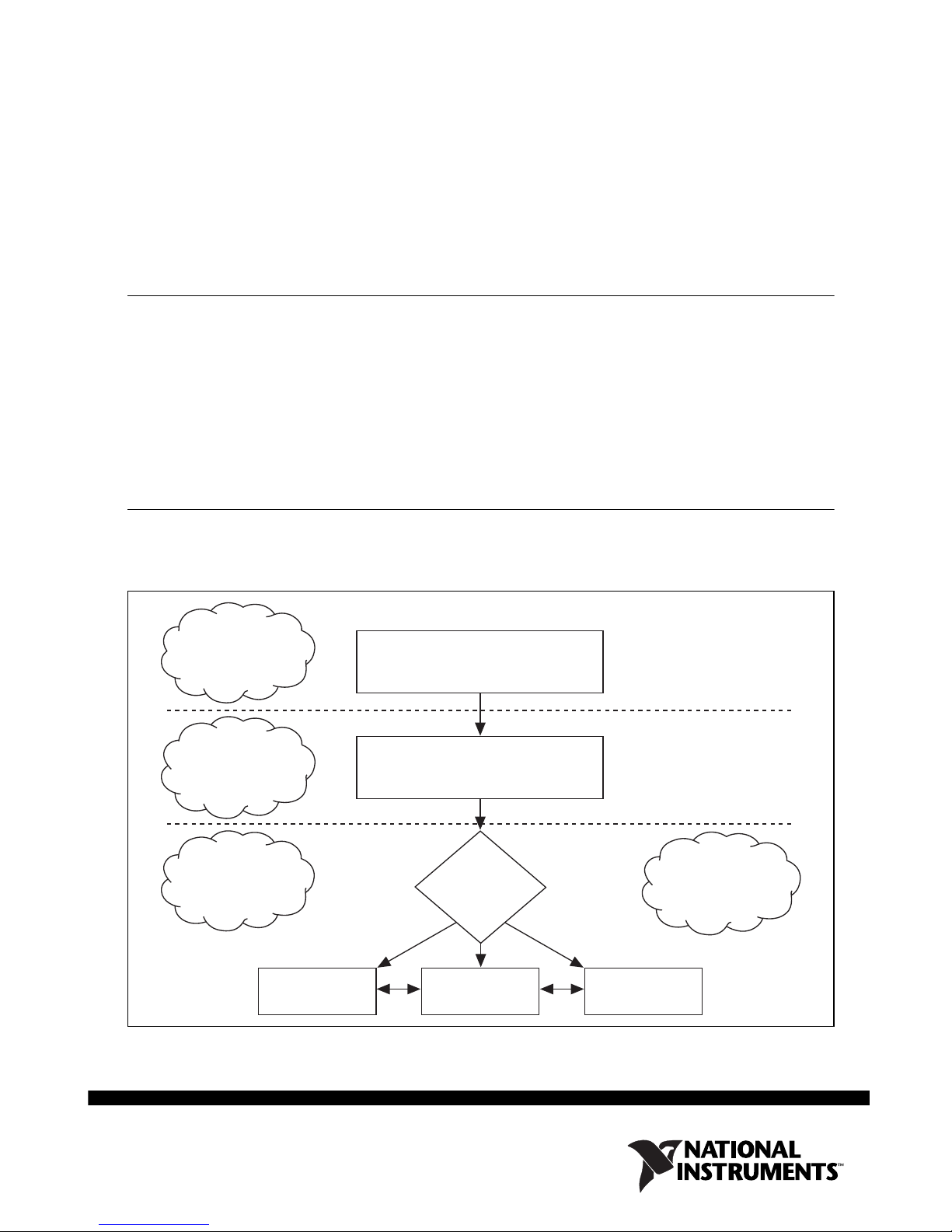
How to Use Your NI FlexRIO Documentation Set
Refer to the Figure 1 and Table 1- for information about how to use your NI FlexRIO
documentation set.
INSTALL Hardware
and Software
CONNECT Signals
and Learn About
Your Adapter
Module
LEARN About
LabVIEW FPGA
Module
LabVIEW FPGA
Module Help
Figure 1. How to Use Your NI FlexRIO Documentation Set
NI FlexRIO FPGA Module
Installation Guide and Specifications
NI FlexRIO Adapter Module
User Guide and Specifications
Are
You New to
LabVIEW FPGA
Module?
Yes No
No
NI FlexRIO
Help
PROGRAM Your
NI FlexRIO System
in LabVIEW FPGA
Module
LabVIEW
Examples
Page 2
Table 1. NI FlexRIO Documentation Locations and Descriptions
Document Location Description
NI FlexRIO FPGA Module
Installation Guide and
Specifications
NI FlexRIO Adapter
Module User Guide and
Specifications
LabVIEW FPGA Module
*
Help
NI FlexRIO Help
LabVIEW Examples Available in LabVIEW
Other Useful Information on ni.com
ni.com/ipnet
ni.com/flexrio
*
These documents are also available at ni.com/manuals.
*
*
*
Available in your FPGA
module hardware kit and
from the Start Menu.
Available from the Start
Menu.
Embedded in LabVIEW
Help.
Available from the Start
Menu.
Example Finder.
Contains LabVIEW FPGA functions and intellectual property to share.
Contains product information and data sheets for NI FlexRIO devices.
Contains installation instructions for your
NI FlexRIO system and specifications for
your FPGA module.
Contains signal information, examples,
and specifications for your adapter
module.
Contains information about the basic
functionality of LabVIEW FPGA Module.
Contains FPGA module, adapter module,
and CLIP configuration information.
Contains examples of how to run FPGA
VIs and Host VIs on your device.
Required Components
The following items are necessary to set up and use your NI FlexRIO system:
❑ The NI FlexRIO hardware device, comprised of the following items:
– NI FlexRIO FPGA module (PXI/PXIe-79xxR)
– NI FlexRIO adapter module
Note You can use the NI FlexRIO FPGA module without an adapter module for
coprocessing or peer-to-peer streaming. The adapter module installation instructions
in this document do not apply to these circumstances.
NI FlexRIO FPGA Module Installation Guide 2 ni.com
Page 3
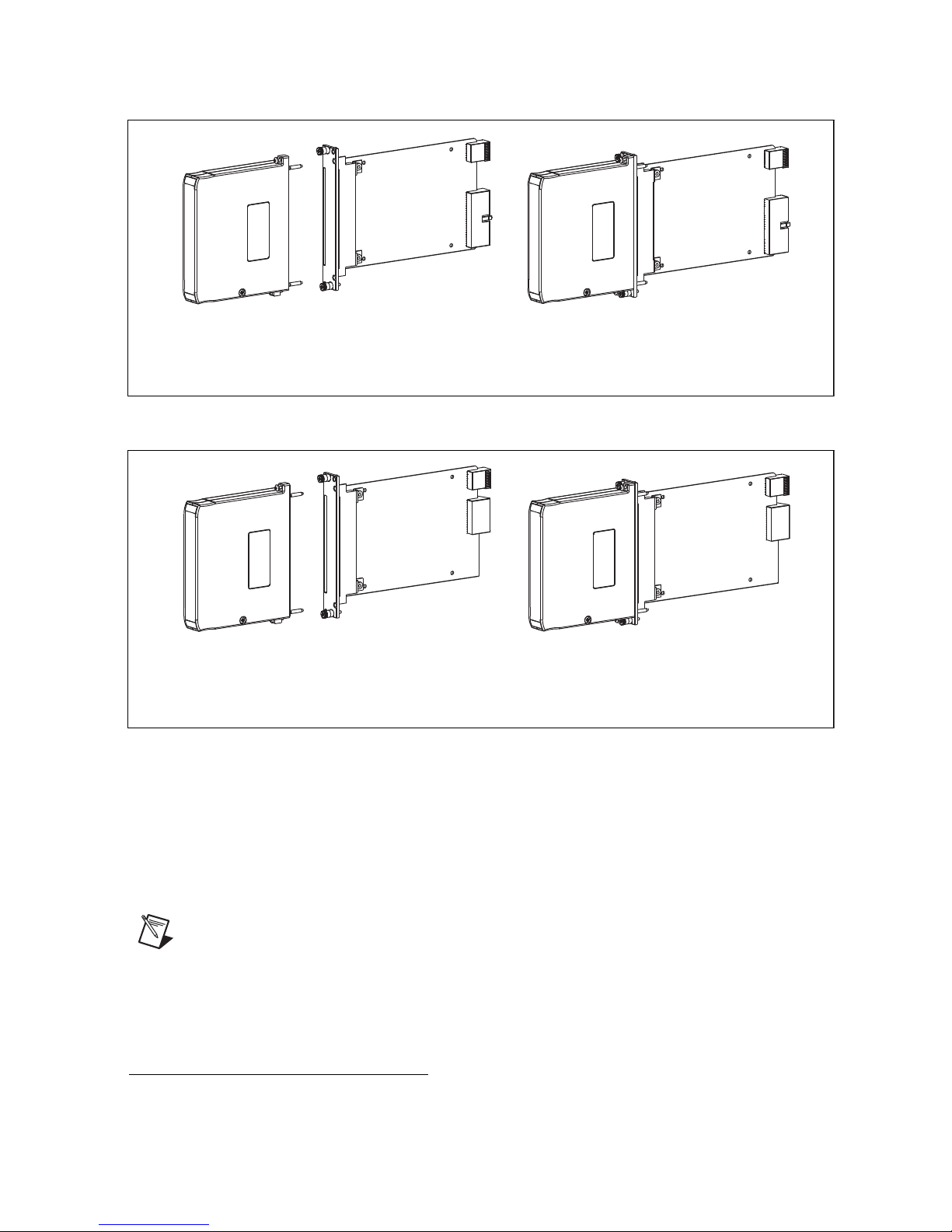
The form factor of the FPGA module (PXI or PXI Express) determines the form factor of the
NI FlexRIO
Adapter Module
+
=
NI FlexRIO PXI Device
NI FlexRIO FPGA
PXI Module
(NI PXI-795xR)
combined module, as shown in Figures 2 and 3.
Figure 2. NI FlexRIO PXI Device
NI FlexRIO
Adapter Module
+
NI FlexRIO FPGA
PXI Express Module
(NI PXI-796xR)
=
NI FlexRIO PXI Express Device
Figure 3. NI FlexRIO PXI Express Device
❑ The following software packages:
–LabVIEW
– LabVIEW FPGA Module
– NI-RIO driver
– NI FlexRIO Adapter Module Support
Note The most recent version of NI FlexRIO Adapter Module Support is available
at
ni.com. Visit ni.com/info and enter famsoftware as the Info Code to
download the latest version of NI FlexRIO Adapter Module Support. You do not
need this software if you are not using an adapter module.
– (Optional) LabVIEW Real-Time Module
1
The NI 1483 adapter module requires the NI-IMAQ instrument driver instead of NI FlexRIO Adapter
Module Support.
1
© National Instruments Corporation 3 NI FlexRIO FPGA Module Installation Guide
Page 4

Refer to Step 1. Install the Application Software and Driver for more information about
NI FlexRIO software support.
❑ One of the following chassis:
– PXI/CompactPCI chassis
– PXI Express/CompactPCI Express chassis
❑ One of the following controllers:
– PXI/CompactPCI embedded controller
– PXI Express/CompactPCI Express embedded controller
– MXI kit and a PC
❑ One of the following operating systems:
– Windows 7
– Windows Vista
– Windows XP Pro x32 Service Pack 1 or 2
❑ At least one cable for connecting signals to the NI FlexRIO device. Refer to your adapter
module documentation for a list of applicable cables and accessories for your NI FlexRIO
system.
Step 1. Install the Application Software and Driver
Before installing your hardware, you must install the application software and instrument driver.
ni.com/info and enter rdsoftwareversion as the Info Code to determine which
Visit
minimum software versions you need for your device. Install the software in the following order:
1. LabVIEW—Refer to the LabVIEW Release Notes for installation instructions for
LabVIEW and system requirements for the LabVIEW software. Refer to the LabVIEW
Upgrade Notes for additional information about upgrading to the most recent version of
LabVIEW for Windows.
Documentation for LabVIEW is available by selecting Start»All Programs»National
Instruments»LabVIEW»LabVIEW Manuals.
2. LabVIEW FPGA Module—Refer to the LabVIEW FPGA Module Release and Upgrade
Notes for installation instructions and information about getting started with the LabVIEW
FPGA Module.
Documentation for the LabVIEW FPGA Module is available by selecting Start»
All Programs»National Instruments»LabVIEW»LabVIEW Manuals.
3. (Optional) LabVIEW Real-Time Module—Refer to the LabVIEW Real-Time Module
Release and Upgrade Notes for system requirements, installation instructions, and
additional information about using the LabVIEW Real-Time Module.
4. NI-RIO—Refer to the NI-RIO Readme on the NI-RIO installation media for system
requirements and installation instructions for the NI-RIO driver.
Documentation for the NI-RIO driver software is available by selecting Start»
All Programs»National Instruments»NI-RIO.
NI FlexRIO FPGA Module Installation Guide 4 ni.com
Page 5
Note If you are not using an adapter module, skip step 5.
5. NI FlexRIO Adapter Module Support—Refer to the NI FlexRIO Adapter Module
Support Readme on the NI FlexRIO Adapter Module Support installation media for system
requirements and installation instructions.
The LabVIEW documents are available from
LabVIEW Manuals directory that contains these documents by selecting Start»All Programs»
National Instruments»LabVIEW»LabVIEW Manuals.
ni.com/manuals. You can also view the
Step 2. Install the NI FlexRIO devices
This section describes how to unpack and install the NI FlexRIO FPGA module and the
NI FlexRIO adapter module.
Note You must install the software before installing the hardware. For software
installation information, refer to Step 1. Install the Application Software and Driver.
Unpacking
The NI FlexRIO FPGA module and the NI FlexRIO adapter module are shipped in antistatic
packages to prevent electrostatic discharge from damaging device components. To prevent such
damage when handling the device, take the following precautions:
• Ground yourself using a grounding strap or by holding a grounded object, such as your
computer chassis.
• Touch the antistatic package to a metal part of the computer chassis before removing the
device from the package.
Caution Never touch the exposed pins of connectors.
Remove the device from the package and inspect the devices for loose components or any other
sign of damage. Notify NI if the device appears damaged in any way. Do not install a damaged
device into the chassis.
Store the NI FlexRIO FPGA module and NI FlexRIO adapter module in the antistatic envelopes
when not in use.
© National Instruments Corporation 5 NI FlexRIO FPGA Module Installation Guide
Page 6

Installing the NI FlexRIO FPGA Module
Complete the following steps to install an NI FlexRIO FPGA module:
Note You must install the software before installing the hardware. For software
installation information, refer to Step 1. Install the Application Software and Driver.
Caution Refer to the Read Me First: Safety and Electromagnetic Compatibility
document packaged with your PXI/PXI Express chassis or device before removing
equipment covers or connecting or disconnecting any signal wires.
1. Power off and unplug the PXI/PXI Express chassis. Refer to your chassis manual to install
or configure the chassis.
2. Identify a supported PXI/PXI Express slot in the chassis. Figure 4 shows the symbols that
indicate the slot types in a PXI/PXI Express chassis.
NI PXIe-1062Q
1 PXI Express System Controller Slot
2 PXI Peripheral Slot
3 PXI Express Hybrid Peripheral Slot
1
2 3
4 PXI Express System Timing Slot
5 PXI Express Peripheral Slot
4
5
Figure 4. Symbols for PXI Express/PXI Express Hybrid/PXI Slots
If you are using a PXI Express chassis, you can place PXI devices in the PXI slots. If a PXI
device is hybrid slot compatible, you can use the PXI Express Hybrid slots. PXI Express
devices can be placed only in PXI Express slots and PXI Express Hybrid slots. Refer to the
chassis documentation for details.
3. Remove the filler panel of an unused PXI/PXI Express slot.
4. Touch any metal part of the chassis to discharge any static electricity.
NI FlexRIO FPGA Module Installation Guide 6 ni.com
Page 7

Place the PXI/PXI Express module edges into the module guides at the top and bottom of
PXI-1000B
1
2
3
4
5
6
the chassis, and slide the module into the chassis until the module is fully inserted, as shown
in Figure 5.
1 PXI/PXI Express Chassis
2 PXI/PXI Express System Controller
3 NI FlexRIO FPGA Module (PXI shown)
4 Front-Panel Mounting Screws
5Module Guides
6 Power Switch
Figure 5. Installing an NI FlexRIO FPGA Module in the PXI/PXI Express Chassis
5. Secure the device front panel to the chassis front panel mounting rail using the front panel
mounting screws.
6. Plug in and power on the PXI/PXI Express chassis.
Confirming That the Device Is Recognized in Measurement &
Automation Explorer (MAX)
To confirm that your device is recognized, complete the following additional steps:
1. Select Start»All Programs»National Instruments»Measurement & Automation.
2. Expand Devices and Interfaces.
3. Verify that the device appears under Devices and Interfaces»RIO Devices, as shown in
Figure 6.
Figure 6. Confirming That the Device is Recognized
© National Instruments Corporation 7 NI FlexRIO FPGA Module Installation Guide
Page 8

Installing the NI FlexRIO Adapter Module
Complete the following steps to connect the NI FlexRIO adapter module to the NI FlexRIO
FPGA module.
Note Skip this step if you are not using an adapter module.
1. Gently insert the guide pins and the high-density card edge of the NI FlexRIO adapter
module into the corresponding connectors of the NI FlexRIO FPGA module, as shown in
Figure 7. The connection may be tight, but do not force the adapter module into place.
4
PXI-1000B
2
1
5
3
1 NI FlexRIO Adapter Module
2Captive Screw
3Guide Pin
4 PXI/PXI Express Chassis
5 NI FlexRIO FPGA Module
Figure 7. Installing the NI FlexRIO Adapter Module
2. Tighten the captive screws on the NI FlexRIO adapter module to secure it to the NI FlexRIO
FPGA module.
3. Launch LabVIEW to begin configuring your NI FlexRIO system.
Note MAX only recognizes which FPGA modules are in the chassis. Your adapter
module will not appear in MAX.
NI FlexRIO FPGA Module Signals
Figure 8 shows the available signals on the NI FlexRIO FPGA module. With the exception of
the two footnotes in the following image, the PXI and PXI Express FPGA modules have the
same pinouts. Refer to your adapter module specifications for your adapter module pinout.
NI FlexRIO FPGA Module Installation Guide 8 ni.com
Page 9

PCB
Secondary Side
.3V
+3
SD
A
TB_Power_Good
+12V
VccoB
Veeprom
GND
RSVD_A2
RSVD_A1
GND
GPIO_16
GPIO_16_n
GND
GPIO_17
GPIO_17_n
GND
GPIO_18
GPIO_18_n
GND
GPIO_19
GPIO_19_n
GND
GPIO_20
GPIO_20_n
GND
GPIO_21
GPIO_21_n
GND
GPIO_22
GPIO_22_n
GND
GPIO_23_CC
Bank 1
GPIO_23_n_CC
GND
GPIO_24_CC
GPIO_24_n_CC
GND
GPIO_25_CC
GPIO_25_n_CC
GND
GPIO_26_CC
GPIO_26_n_CC
GND
GPIO_27
GPIO_27_n
GND
GPIO_28
GPIO_28_n
GND
GPIO_29
GPIO_29_n
GND
P1
S74
S73
P2
S72
S71
G37
S70
S69
G36
S68
S67
G35
S66
S65
G34
S64
S63
G33
S62
S61
G32
S60
S59
G31
S58
S57
G30
S56
S55
G29
S54
S53
G28
S52
S51
G27
S50
S49
G26
S48
S47
G25
S46
S45
G24
S44
S43
G23
S42
S41
G22
PCB
Primary Side
P1
+3.3V
S148
SCL
S147
TB_Present_n
P2
+12V
S146
VccoA
S145
RSVD
G37
GND
S144
IoModSyncClk_n
IoModSyncClk
S143
G36
GND
S142
GPIO_0
S141
GPIO_0_n
G35
GND
S140
GPIO_1
S139
GPIO_1_n
G34
GND
S138
GPIO_2
S137
GPIO_2_n
G33
GND
S136
GPIO_3
S135
GPIO_3_n
G32
GND
S134
GPIO_4_CC
S133
GPIO_4_n_CC
G31
GND
S132
GPIO_5_CC
S131
GPIO_5_n_CC
G30
GND
30
S1
GPIO_6_CC
S1
29
GPIO_6_n_CC
G29
GND
S128
GPIO_7_CC
S127
GPIO_7_n_CC
G28
GND
S126
GPIO_8
S125
GPIO_8_n
G27
GND
S124
GPIO_9
S123
GPIO_9_n
G26
GND
S122
GPIO_10
S121
GPIO_10_n
G25
GND
S120
GPIO_11
S119
GPIO_11_n
G24
GND
S118
GPIO_12
S117
GPIO_12_n
G23
GND
S116
GPIO_13
S115
GPIO_13_n
G22
GND
PCB
Secondary Side
GND
GClk_L
VDS_n
GClk_LVDS
GND
GPIO_30
GPIO_30_n
GND
1
2
NI PXI-795xR
FlexRIO
Bank 0
Bank 1
GPIO_31
GPIO_31_n
GND
GPIO_32
GPIO_32_n
GND
GPIO_33
GPIO_33_n
GND
GPIO_34
GPIO_34_n
GND
GPIO_35
GPIO_35_n
GND
GPIO_36
GPIO_36_n
GND
GPIO_37_CC
GPIO_37_n_CC
GND
GPIO_38_CC
GPIO_38_n_CC
GND
GPIO_39_CC
GPIO_39_n_CC
GND
GPIO_40_CC
GPIO_40_n_CC
GND
GPIO_41
Bank 2
GPIO_41_n
GND
GPIO_42
GPIO_42_n
GND
GPIO_43
GPIO_43_n
GND
GPIO_44
GPIO_44_n
GND
GPIO_45
GPIO_45_n
GND
GPIO_46
GPIO_46_n
GND
GPIO_47
GPIO_47_n
GND
GPIO_48
GPIO_48_n
GND
G21
S40
S39
G20
S38
S37
G19
S36
S35
G18
S34
S33
G17
S32
S31
G16
S30
S29
G15
S28
S27
G14
S26
S25
G13
S24
S23
G12
S22
S21
G11
S20
S19
G10
S18
S17
G9
S16
S15
G8
S14
S13
G7
S12
S11
G6
S10
S9
G5
S8
S7
G4
S6
S5
G3
S4
S3
G2
S2
S1
G1
PCB
Primary Side
G21
GND
S114
GND
S113
GClk_SE
G20
GND
S112
GPIO_14
S111
GPIO_14_n
G19
GND
S110
GPIO_15
S109
GPIO_15_n
G18
GND
GPIO_49
S108
S107
GPIO_49_n
G17
GND
S106
GPIO_50
S105
GPIO_50_n
G16
GND
S104
GPIO_51
S103
GPIO_51_n
G15
GND
S102
GPIO_52
S101
GPIO_52_n
G14
GND
S100
GPIO_53
S99
GPIO_53_n
G13
GND
S98
GPIO_54
S97
GPIO_54_n
G12
GND
S96
GPIO_55
S95
GPIO_55_n
G11
GND
S94
GPIO_56_CC
S93
GPIO_56_n_CC
G10
GND
S92
GPIO_57_CC
S91
GPIO_57_n_CC
G9
GND
S90
GPIO_58_CC
S89
GPIO_58_n_CC
G8
GND
S88
GPIO_59_CC
S87
GPIO_59_n_CC
G7
GND
S86
GPIO_60
S85
GPIO_60_n
G6
GND
S84
GPIO_61
S83
GPIO_61_n
G5
GND
S82
GPIO_62
S81
GPIO_62_n
G4
GND
S80
GPIO_63
S79
GPIO_63_n
G3
GND
S78
GPIO_64
S77
GPIO_64_n
G2
GND
S7
6
GPIO_65
S75
GPIO_65_n
G1
GND
Bank 0
Bank 3
1RSVD_B2 on the NI PXI-795xR 2RSVD_B1 on the NI PXI-795xR
Figure 8. NI FlexRIO FPGA Module Front Connector Pin Assignments and Locations
© National Instruments Corporation 9 NI FlexRIO FPGA Module Installation Guide
Page 10

Specifications
This section lists the specifications for your NI FlexRIO FPGA module. Refer to your adapter
module documentation for the adapter module specifications. NI FlexRIO FPGA modules
include the following devices:
• NI PXI-7951R
• NI PXI-7952R
• NI PXI-7953R
• NI PXI-7954R
• NI PXIe-7961R
• NI PXIe-7962R
• NI PXIe-7965R
• NI PXIe-7966R
Note Typical values are representative of an average unit operating at room
temperature. These specifications are typical at 25 °C unless otherwise noted.
Reconfigurable FPGA
DSP48 Slices
LUTs/
Device FPGA
NI PXI-7951R Virtex-5 LX30 19,200 32 1,152
NI PXI-7952R Virtex-5 LX50 28,800 48 1,728
NI PXI-7953R Virtex-5 LX85 51,840 48 3,456
NI PXI-7954R Virtex-5 LX110 69,120 64 4,608
NI PXIe-7961R Virtex-5 SX50T 32,640 288 4,752
NI PXIe-7962R Virtex-5 SX50T 32,640 288 4,752
NI PXIe-7965R/7966R* Virtex-5 SX95T 58,880 640 8,784
* These two devices have different speed grade FPGAs: –1 for the NI PXIe-7965R and –2 for the
NI PXIe-7966R. For more information about Xilinx Virtex-5 FPGA speed grades, refer to the Virtex-5
FPGA Data Sheet: DC and Switching Characteristics available at
Flip-Flops
www.xilinx.com.
× 18
(25
Multiplier)
Embedded
Block RAM
(kbits)
Default timebase ............................................... 40 MHz
Timebase reference sources
NI PXI-795xR ........................................... PXI 10 MHz (PXI_CLK10)
NI PXIe-796xR .........................................PXI Express 100 MHz (PXIe_CLK100)
NI FlexRIO FPGA Module Installation Guide 10 ni.com
Page 11

Timebase accuracy
NI PXI-795xR........................................... ±100 ppm, 250 ps peak-to-peak jitter
NI PXIe-796xR ......................................... ±50 ppm, 250 ps peak-to-peak jitter
Data transfers .................................................... DMA, interrupts, programmed I/O
Number of DMA channels
NI PXI-795xR........................................... 3
NI PXIe-796xR ......................................... 16
FPGA Digital Input/Output
Number of general-purpose
channels ............................................................ 132, configurable as 132 single-ended,
66 differential, or a combination of both
Channels per bank
Bank 0/Bank 2 .......................................... 32, single-ended per bank
Bank 1/Bank 3 .......................................... 34, single-ended per bank
Compatibility .................................................... Configured through the FPGA and based on the
attached adapter module; 1.2 V, 1.5 V, 1.8 V,
2.5 V, 3.3 V I/O standards (refer to
www.xilinx.com)
1
Protection.......................................................... Refer to
www.xilinx.com
Current .............................................................. Refer to www.xilinx.com
Maximum I/O data rates
Single-ended ............................................. 400 Mb/s for LVDCI25
Differential................................................ 1 Gb/s for LVDS
Global clock inputs ........................................... 1 LVTTL, 1 LVDS
Connection resources
NI PXI-795xR........................................... PXI triggers, PXI_CLK10, and PXI star trigger
NI PXIe-796xR ......................................... PXI triggers, PXI_CLK10, PXI star trigger,
PXIe_DStarA, PXIe_DStarB, PXIe_DStarC,
and PXIe_Sync100
1
The 132 channels span across four FPGA banks. Refer to the NI FlexRIO FPGA Module Signals section
for more information about banks.
© National Instruments Corporation 11 NI FlexRIO FPGA Module Installation Guide
Page 12

Onboard DRAM
Memory size
NI PXI-795xR ........................................... 2 banks, 64 MB per bank
NI PXIe-796xR ......................................... 2 banks, 256 MB per bank
Maximum theoretical data rate
NI PXI-795xR ...........................................800 MB/s per bank
NI PXIe-796xR ......................................... 1.6 GB/s per bank
1
Bus Interface
PXI ....................................................................Master, slave
PXI Express
Form factor................................................x4 PXI Express, specification v1.0 compliant
Slot compatibility......................................x4, x8, and x16 PXI Express or PXI Express
hybrid slots
Maximum Power Requirements
NI PXI-795xR
+5 VDC (±5%)..........................................2 A
+3.3 VDC (±5%)....................................... 2 A
+12 V ........................................................ 0.5 A
–12 V......................................................... 0 A
NI PXIe-796xR
+3.3 VDC (±5%)....................................... 3 A
+12 V ........................................................ 2 A
2
Physical
Dimensions (not including connectors)
NI PXI-795xR ........................................... 18.8 cm × 12.9 cm
(7.4 in. × 5.1 in.)
NI PXIe-796xR ......................................... 16.1 cm × 10.8 cm
(6.3 in. × 4.3 in.)
Weight
NI PXI-795xR ...........................................190 g (6.7 oz)
NI PXIe-796xR .........................................213 g (7.5 oz)
I/O connector ....................................................High-density card edge
1
The NI PXI-7951R and NI PXIe-7961R devices do not have onboard DRAM.
2
Power requirements are dependent on the adapter module and contents of the LabVIEW FPGA VI used
in your application.
NI FlexRIO FPGA Module Installation Guide 12 ni.com
Page 13

Maximum Working Voltage
1
Maximum working voltage refers to the signal voltage plus the common-mode voltage.
Channel-to-earth ............................................... 0 V to 3.3 V, Measurement Category I
Channel-to-channel........................................... 0 V to 3.3 V, Measurement Category I
Caution Do not use this device for connecting to signals in Measurement Categories
II, III, or IV.
Environmental
This device is intended for indoor use only.
Operating environment ..................................... 0 °C to 55 °C,
tested in accordance with IEC-60068-2-1 and
IEC-60068-2-2.
Relative humidity range.................................... 10% to 90%, noncondensing,
tested in accordance with IEC-60068-2-56.
Altitude ............................................................. 2,000 m at 25 °C ambient temperature
Pollution Degree ............................................... 2
Storage environment
Ambient temperature range ...................... –20 °C to 70 °C,
tested in accordance with IEC-60068-2-1 and
IEC-60068-2-2.
Relative humidity range............................ 5% to 95%, noncondensing,
tested in accordance with IEC-60068-2-56.
Note Clean the device with a soft, non-metallic brush. Make sure that the device is
completely dry and free from contaminants before returning it to service.
Shock and Vibration
Operational shock ............................................. 30 g peak, half-sine, 11 ms pulse,
tested in accordance with IEC-60068-2-27.
Test profile developed in accordance with
MIL-PRF-28800F.
Random vibration
Operating .................................................. 5 Hz to 500 Hz, 0.3 g
Nonoperating ............................................ 5 Hz to 500 Hz, 2.4 g
tested in accordance with IEC-60068-2-64.
Nonoperating test profile exceeds the
requirements of MIL-PRF-28800F, Class 3.
rms
rms
,
1
Voltage ranges are dependent on the I/O standards available for your application. For more information on
available I/O standards, refer to Xilinx documentation, available at
© National Instruments Corporation 13 NI FlexRIO FPGA Module Installation Guide
www.xilinx.com.
Page 14

Safety
This product meets the requirements of the following standards of safety for electrical equipment
for measurement, control, and laboratory use:
• IEC 61010-1, EN 61010-1
• UL 61010-1, CSA 61010-1
Note For UL and other safety certifications, refer to the product label or the Online
Product Certification section.
Electromagnetic Compatibility
This product meets the requirements of the following EMC standards for electrical equipment
for measurement, control, and laboratory use:
• EN 61326-1 (IEC 61326-1): Class A emissions; Basic immunity
• EN 55011 (CISPR 11): Group 1, Class A emissions
• AS/NZS CISPR 11: Group 1, Class A emissions
• FCC 47 CFR Part 15B: Class A emissions
• ICES-001: Class A emissions
Note For the standards applied to assess the EMC of this product, refer to the Online
Product Certification section.
Note EMC compliance evaluated with a wrapback adapter module and general
purpose I/O (GPIO) signals configured to LVTTL I/O standard, slew rate set to slow,
and drive strength set to 6 mA. EMC compliance of other I/O standards, faster slew
rates, and greater drive strength is not guaranteed.
CE Compliance
This product meets the essential requirements of applicable European Directives as follows:
• 2006/95/EC; Low-Voltage Directive (safety)
• 2004/108/EC; Electromagnetic Compatibility Directive (EMC)
Online Product Certification
Refer to the product Declaration of Conformity (DoC) for additional regulatory compliance
information. To obtain product certifications and the DoC for this product, visit
certification
Certification column.
, search by model number or product line, and click the appropriate link in the
ni.com/
NI FlexRIO FPGA Module Installation Guide 14 ni.com
Page 15

Environmental Management
⬉ᄤֵᙃѻક∵ᶧࠊㅵ⧚ࡲ⊩ ˄Ё
RoHS
˅
Ёᅶ᠋
National Instruments
ヺড়Ё⬉ᄤֵᙃѻકЁ䰤ࠊՓ⫼ᶤѯ᳝ᆇ⠽䋼ᣛҸ
(RoHS)
DŽ݇Ѣ
National Instruments
Ё
RoHS
ড়㾘ᗻֵᙃˈ䇋ⱏᔩ
ni.com/
environment/rohs_china
DŽ
(For information about China RoHS compliance,
go to
ni.com/environment/rohs_china
.)
National Instruments is committed to designing and manufacturing products in an
environmentally responsible manner. NI recognizes that eliminating certain hazardous
substances from our products is beneficial not only to the environment but also to NI customers.
For additional environmental information, refer to the NI and the Environment Web page at
ni.com/environment. This page contains the environmental regulations and directives with
which NI complies, as well as other environmental information not included in this document.
Waste Electrical and Electronic Equipment (WEEE)
EU Customers At the end of the product life cycle, all products must be sent to a
WEEE recycling center. For more information about WEEE recycling centers,
National Instruments WEEE initiatives, and compliance with WEEE Directive
2002/96/EC on Waste and Electronic Equipment,
ni.com/environment/weee.
visit
Where to Go for Support
The National Instruments Web site is your complete resource for technical support. At
ni.com/support you have access to everything from troubleshooting and application
development self-help resources to email and phone assistance from NI Application Engineers.
National Instruments corporate headquarters is located at 11500 North Mopac Expressway,
Austin, Texas, 78759-3504. National Instruments also has offices located around the world to
help address your support needs. For telephone support in the United States, create your service
request at
telephone support outside the United States, visit the Worldwide Offices section of ni.com/
niglobal
support phone numbers, email addresses, and current events.
ni.com/support and follow the calling instructions or dial 512 795 8248. For
to access the branch office Web sites, which provide up-to-date contact information,
© National Instruments Corporation 15 NI FlexRIO FPGA Module Installation Guide
Page 16

LabVIEW, National Instruments, NI, ni.com, the National Instruments corporate logo, and the Eagle logo are trademarks of National Instruments
Corporation. Refer to the Trademark Information at ni.com/trademarks for other National Instruments trademarks. Other product and
company names mentioned herein are trademarks or trade names of their respective companies. For patents covering National Instruments
products/technology, refer to the appropriate location: Help»Patents in your software, the patents.txt file on your media, or the National
Instruments Patents Notice at ni.com/patents. Refer to the Export Compliance Information at ni.com/legal/export-compliance
for the National Instruments global trade compliance policy and how to obtain relevant HTS codes, ECCNs, and other import/export data.
© 2010–2011 National Instruments Corporation. All rights reserved.
373047B-01 Oct11
 Loading...