

Page 1

Fieldbus
NI-FBUSTM Configurator
User Manual
NI-FBUS Configurator User Manual
May 2003 Edition
Part Number 370514B-01
Page 2

Support
Worldwide Technical Support and Product Information
ni.com
National Instruments Corporate Headquarters
11500 North Mopac Expressway Austin, Texas 78759-3504 USA Tel: 512 683 0100
Worldwide Offices
Australia 1800 300 800, Austria 43 0 662 45 79 90 0, Belgium 32 0 2 757 00 20, Brazil 55 11 3262 3599,
Canada (Calgary) 403 274 9391, Canada (Montreal) 514 288 5722, Canada (Ottawa) 613 233 5949,
Canada (Québec) 514 694 8521, Canada (Toronto) 905 785 0085, Canada (Vancouver) 514 685 7530,
China 86 21 6555 7838, Czech Republic 420 2 2423 5774, Denmark 45 45 76 26 00,
Finland 385 0 9 725 725 11, France 33 0 1 48 14 24 24, Germany 49 0 89 741 31 30, Greece 30 2 10 42 96 427,
India 91 80 51190000, Israel 972 0 3 6393737, Italy 39 02 413091, Japan 81 3 5472 2970,
Korea 82 02 3451 3400, Malaysia 603 9131 0918, Mexico 001 800 010 0793, Netherlands 31 0 348 433 466,
New Zealand 1800 300 800, Norway 47 0 66 90 76 60, Poland 48 0 22 3390 150, Portugal 351 210 311 210,
Russia 7 095 238 7139, Singapore 65 6226 5886, Slovenia 386 3 425 4200, South Africa 27 0 11 805 8197,
Spain 34 91 640 0085, Sweden 46 0 8 587 895 00, Switzerland 41 56 200 51 51, Taiwan 886 2 2528 7227,
Thailand 662 992 7519, United Kingdom 44 0 1635 523545
For further support information, refer to the Technical Support and Professional Services appendix. To comment
on the documentation, send email to techpubs@ni.com.
© 2002–2003 National Instruments Corporation. All rights reserved.
Page 3

Important Information
Warranty
The media on which you receive National Instruments software are warranted not to fail to execute programming instructions, due to defects
in materials and workmanship, for a period of 90 days from date of shipment, as evidenced by receipts or other documentation. National
Instruments will, at its option, repair or replace software media that do not execute programming instructions if National Instruments receives
notice of such defects during the warranty period. National Instruments does not warrant that the operation of the software shall be
uninterrupted or error free.
A Return Material Authorization (RMA) number must be obtained from the factory and clearly marked on the outside of the package before
any equipment will be accepted for warranty work. National Instruments will pay the shipping costs of returning to the owner parts which are
covered by warranty.
National Instruments believes that the information in this document is accurate. The document has been carefully reviewed for technical
accuracy. In the event that technical or typographical errors exist, National Instruments reserves the right to make changes to subsequent
editions of this document without prior notice to holders of this edition. The reader should consult National Instruments if errors are suspected.
In no event shall National Instruments be liable for any damages arising out of or related to this document or the information contained in it.
E
XCEPT AS SPECIFIED HEREIN, NATIONAL INSTRUMENTS MAKES NO WARRANTIES, EXPRESS OR IMPLIED, AND SPECIFICALLY DISCLAIMS ANY WAR RANTY OF
MERCHANTABILITY OR FITNESS FOR A PARTICULAR PURPOSE . CUSTOMER’S RIGHT TO RECOVER DAMAGES CAUSED BY FAULT OR NEGLIGENCE ON THE PART OF
N
ATIONAL INSTRUMENTS SHALL BE LIMITED TO THE AMOUNT THERETOFORE PAID BY THE CUSTOMER. NATIONAL INSTRUMENTS WILL NOT BE LIABLE FOR
DAMAGES RESULTING FROM LOSS OF DATA, PROFITS, USE OF PRODUCTS, OR INCIDENTAL OR CONSEQUENTIAL DAMAGES, EVEN IF ADVISED OF THE POSS IBILITY
THEREOF. This limitation of the liability of National Instruments will apply regardless of the form of action, whether in contract or tort, including
negligence. Any action against National Instruments must be brought within one year after the cause of action accrues. National Instruments
shall not be liable for any delay in performance due to causes beyond its reasonable control. The warranty provided herein does not cover
damages, defects, malfunctions, or service failures caused by owner’s failure to follow the National Instruments installation, operation, or
maintenance instructions; owner’s modification of the product; owner’s abuse, misuse, or negligent acts; and power failure or surges, fire,
flood, accident, actions of third parties, or other events outside reasonable control.
Copyright
Under the copyright laws, this publication may not be reproduced or transmitted in any form, electronic or mechanical, including photocopying,
recording, storing in an information retrieval system, or translating, in whole or in part, without the prior written consent of National
Instruments Corporation.
Trademarks
FieldPoint™, Lookout™, National Instruments™, National Instruments Alliance Program™, NI™, NI-FBUS™, and ni.com™ are trademarks of
National Instruments Corporation.
Product and company names mentioned herein are trademarks or trade names of their respective companies.
Patents
For patents covering National Instruments products, refer to the appropriate location: Help»Patents in your software, the patents.txt file
on your CD, or
ni.com/patents.
WARNING REGARDING USE OF NATIONAL INSTRUMENTS PRODUCTS
(1) NATIONAL INSTRUMENTS PRODUCTS ARE NOT DESIGNED WITH COMPONENTS AND TESTING FOR A LEVEL OF
RELIABILITY SUITABLE FOR USE IN OR IN CONNECTION WITH SURGICAL IMPLANTS OR AS CRITICAL COMPONENTS IN
ANY LIFE SUPPORT SYSTEMS WHOSE FAILURE TO PERFORM CAN REASONABLY BE EXPECTED TO CAUSE SIGNIFICANT
INJURY TO A HUMAN.
(2) IN ANY APPLICATION, INCLUDING THE ABOVE, RELIABILITY OF OPERATION OF THE SOFTWARE PRODUCTS CAN BE
IMPAIRED BY ADVERSE FACTORS, INCLUDING BUT NOT LIMITED TO FLUCTUATIONS IN ELECTRICAL POWER SUPPLY,
COMPUTER HARDWARE MALFUNCTIONS, COMPUTER OPERATING SYSTEM SOFTWARE FITNESS, FITNESS OF COMPILERS
AND DEVELOPMENT SOFTWARE USED TO DEVELOP AN APPLICATION, INSTALLATION ERRORS, SOFTWARE AND
HARDWARE COMPATIBILITY PROBLEMS, MALFUNCTIONS OR FAILURES OF ELECTRONIC MONITORING OR CONTROL
DEVICES, TRANSIENT FAILURES OF ELECTRONIC SYSTEMS (HARDWARE AND/OR SOFTWARE), UNANTICIPATED USES OR
MISUSES, OR ERRORS ON THE PART OF THE USER OR APPLICATIONS DESIGNER (ADVERSE FACTORS SUCH AS THESE ARE
HEREAFTER COLLECTIVELY TERMED “SYSTEM FAILURES”). ANY APPLICATION WHERE A SYSTEM FAILURE WOULD
CREATE A RISK OF HARM TO PROPERTY OR PERSONS (INCLUDING THE RISK OF BODILY INJURY AND DEATH) SHOULD
NOT BE RELIANT SOLELY UPON ONE FORM OF ELECTRONIC SYSTEM DUE TO THE RISK OF SYSTEM FAILURE. TO AVOID
DAMAGE, INJURY, OR DEATH, THE USER OR APPLICATION DESIGNER MUST TAKE REASONABLY PRUDENT STEPS TO
PROTECT AGAINST SYSTEM FAILURES, INCLUDING BUT NOT LIMITED TO BACK-UP OR SHUT DOWN MECHANISMS.
BECAUSE EACH END-USER SYSTEM IS CUSTOMIZED AND DIFFERS FROM NATIONAL INSTRUMENTS' TESTING
PLATFORMS AND BECAUSE A USER OR APPLICATION DESIGNER MAY USE NATIONAL INSTRUMENTS PRODUCTS IN
COMBINATION WITH OTHER PRODUCTS IN A MANNER NOT EVALUATED OR CONTEMPLATED BY NATIONAL
INSTRUMENTS, THE USER OR APPLICATION DESIGNER IS ULTIMATELY RESPONSIBLE FOR VERIFYING AND VALIDATING
THE SUITABILITY OF NATIONAL INSTRUMENTS PRODUCTS WHENEVER NATIONAL INSTRUMENTS PRODUCTS ARE
INCORPORATED IN A SYSTEM OR APPLICATION, INCLUDING, WITHOUT LIMITATION, THE APPROPRIATE DESIGN,
PROCESS AND SAFETY LEVEL OF SUCH SYSTEM OR APPLICATION.
Page 4

Compliance
FCC/Canada Radio Frequency Interference Compliance
Determining FCC Class
The Federal Communications Commission (FCC) has rules to protect wireless communications from interference. The FCC
places digital electronics into two classes. These classes are known as Class A (for use in industrial-commercial locations only)
or Class B (for use in residential or commercial locations). All National Instruments (NI) products are FCC Class A products.
Depending on where it is operated, this Class A product could be subject to restrictions in the FCC rules. (In Canada, the
Department of Communications (DOC), of Industry Canada, regulates wireless interference in much the same way.) Digital
electronics emit weak signals during normal operation that can affect radio, television, or other wireless products.
All Class A products display a simple warning statement of one paragraph in length regarding interference and undesired
operation. The FCC rules have restrictions regarding the locations where FCC Class A products can be operated.
Consult the FCC Web site at
FCC/DOC Warnings
This equipment generates and uses radio frequency energy and, if not installed and used in strict accordance with the instructions
in this manual and the CE marking Declaration of Conformity*, may cause interference to radio and television reception.
Classification requirements are the same for the Federal Communications Commission (FCC) and the Canadian Department of
Communications (DOC).
Changes or modifications not expressly approved by NI could void the user’s authority to operate the equipment under the FCC
Rules.
Class A
Federal Communications Commission
This equipment has been tested and found to comply with the limits for a Class A digital device, pursuant to part 15 of the FCC
Rules. These limits are designed to provide reasonable protection against harmful interference when the equipment is operated
in a commercial environment. This equipment generates, uses, and can radiate radio frequency energy and, if not installed and
used in accordance with the instruction manual, may cause harmful interference to radio communications. Operation of this
equipment in a residential area is likely to cause harmful interference in which case the user is required to correct the interference
at their own expense.
www.fcc.gov for more information.
Canadian Department of Communications
This Class A digital apparatus meets all requirements of the Canadian Interference-Causing Equipment Regulations.
Cet appareil numérique de la classe A respecte toutes les exigences du Règlement sur le matériel brouilleur du Canada.
Compliance to EU Directives
Readers in the European Union (EU) must refer to the manufacturer’s Declaration of Conformity (DoC) for information*
pertaining to the CE marking compliance scheme. The manufacturer includes a DoC for most hardware products except for those
bought from OEMs. In addition, DoCs are usually not provided if compliance is not required, for example electrically benign
apparatus or cables.
To obtain the DoC for this product, click Declaration of Conformity at
by product family. Select the appropriate product family, followed by your product, and a link to the DoC appears in Adobe
Acrobat format. Click the Acrobat icon to download or read the DoC.
* The CE marking Declaration of Conformity contains important supplementary information and instructions for the user or
installer.
ni.com/hardref.nsf/. This Web site lists the DoCs
Page 5

Conventions
The following conventions are used in this manual:
» The » symbol leads you through nested menu items and dialog box options
to a final action. The sequence File»Page Setup»Options directs you to
pull down the File menu, select the Page Setup item, and select Options
from the last dialog box.
This icon denotes a tip, which alerts you to advisory information.
This icon denotes a note, which alerts you to important information.
This icon denotes a caution, which advises you of precautions to take to
avoid injury, data loss, or a system crash.
bold Bold text denotes items that you must select or click in the software, such
as menu items and dialog box options. Bold text also denotes parameter
names.
Fieldbus The generic term fieldbus refers to any bus that connects to field devices.
This includes Foundation Fieldbus, CAN, DNET, and Profibus. In this
manual, the term Fieldbus refers specifically to the Foundation Fieldbus.
italic Italic text denotes variables, emphasis, a cross reference, or an introduction
to a key concept. This font also denotes text that is a placeholder for a word
or value that you must supply.
monospace Text in this font denotes text or characters that you should enter from the
keyboard, sections of code, programming examples, and syntax examples.
This font is also used for the proper names of disk drives, paths, directories,
programs, subprograms, subroutines, device names, functions, operations,
variables, filenames and extensions, and code excerpts.
monospace bold Bold text in this font denotes the messages and responses that the computer
automatically prints to the screen. This font also emphasizes lines of code
that are different from the other examples.
monospace italic
Italic text in this font denotes text that is a placeholder for a word or value
that you must supply.
Page 6

Contents
Chapter 1
NI-FBUS Configurator Overview
Introduction to the NI-FBUS Configurator ...................................................................1-1
NI-FBUS Configurator Windows ..................................................................................1-1
Configuration Tree ..........................................................................................1-2
Help Window...................................................................................................1-3
Status Window.................................................................................................1-3
Status Tab..........................................................................................1-3
Download Tab...................................................................................1-4
Errors Tab .........................................................................................1-4
Middle Frame.................................................................................................................1-4
Function Block Application Editor Window...................................................1-6
Schedule Window............................................................................................1-6
Device Window ...............................................................................................1-8
Network Parameters Window........................................................................................1-8
Block Configuration Window........................................................................................1-9
Changing Parameter Settings ..........................................................................1-10
Block Configuration Window Icons................................................................1-10
Block Configuration Window Tabs.................................................................1-10
Block Configuration Window Units................................................................1-11
Chapter 2
Using the NI-FBUS Configurator
Start the NI-FBUS Configurator and NIFB Process......................................................2-1
Create a New Project .....................................................................................................2-1
Open an Existing Project ...............................................................................................2-2
Upload Project Configuration........................................................................................2-3
Set Device Addresses.....................................................................................................2-3
Function Block Instantiation and Deletion ....................................................................2-4
Set Device or Block Tags ..............................................................................................2-5
Function Block Modes...................................................................................................2-6
The MODE_BLK Parameter...........................................................................2-6
Configure Block Parameters..........................................................................................2-7
Categorizing Block Parameters .......................................................................2-7
Adding Tabs......................................................................................2-7
Customizing Parameters on a Tab ....................................................2-8
Removing Tabs .................................................................................2-8
Modify Block Configuration Window View ....................................2-8
© National Instruments Corporation vii NI-FBUS Configurator User Manual
Page 7

Contents
Editing Block Parameters................................................................................ 2-9
Updating Block Parameters Values ................................................................ 2-10
Manually Update Block Parameters ................................................. 2-10
Automatically Update Block Parameters ......................................... 2-10
Create and Edit Function Block Applications ............................................................... 2-11
Add Blocks to the Function Block Application ..............................................2-11
Connecting Blocks .......................................................................................... 2-12
Wiring Blocks Manually .................................................................. 2-12
Checking for Function Block Application Errors............................. 2-14
Customizing Your Function Block Application ............................... 2-14
Using Templates .............................................................................................2-14
Inserting Templates .......................................................................... 2-15
Creating Templates...........................................................................2-17
Export Function Block Application Image ..................................................... 2-17
Defining Loops.............................................................................................................. 2-17
Defining Multiple Loops Running at Different Rates .................................... 2-18
Determining Function Block Execution Time.................................. 2-20
Changing the Block Execution Order ............................................................. 2-20
Setting the Stale Limit ...................................................................... 2-21
Using Menus and Methods............................................................................................ 2-22
Configuring Alarms....................................................................................................... 2-22
Configuring Trends ....................................................................................................... 2-23
View and Edit a Schedule.............................................................................................. 2-24
Change the Link Active Schedule................................................................... 2-24
Multiple Loop Representation ........................................................................ 2-25
Set Network Parameters ................................................................................................ 2-26
Change Language .......................................................................................................... 2-26
Save a Project Configuration......................................................................................... 2-26
Download a Project Configuration................................................................................ 2-27
Download Options .......................................................................................... 2-28
Write Contained Block Parameters .................................................. 2-28
Clear Devices.................................................................................... 2-28
Automatic Mode Handling ............................................................... 2-28
Verify and Diff ................................................................................. 2-29
Bringing a Block Online ................................................................................. 2-29
Monitoring Parameters .................................................................................................. 2-30
Verify a Configuration .................................................................................................. 2-30
Quick Verification........................................................................................... 2-30
Compare Two Configurations......................................................................... 2-31
Check for Errors.............................................................................................. 2-31
Add An Additional Function Block Application........................................................... 2-31
Replace Devices ............................................................................................................ 2-32
Reset a Device to Factory Defaults ............................................................................... 2-32
Change Device Type ..................................................................................................... 2-32
NI-FBUS Configurator User Manual viii ni.com
Page 8

Export & Import Parameters..........................................................................................2-33
Set Preferences...............................................................................................................2-34
Changing the Software Key...........................................................................................2-34
Print................................................................................................................................2-35
Chapter 3
NI-FBUS Configurator Tutorials
Tutorial 1: Connect to Network and Hardware .............................................................3-1
Tutorial 2: Create Basic Connections to AI and AO Blocks .........................................3-2
Tutorial 3: PID Control of a Simulated Process ............................................................3-5
Chapter 4
Parameters
Alarming Parameters .....................................................................................................4-1
Diagnostic Parameters ...................................................................................................4-2
Faultstate Parameters .....................................................................................................4-2
Scaling Parameters.........................................................................................................4-3
I/O Parameters ...............................................................................................................4-7
Limiting Parameters.......................................................................................................4-7
Mode Shedding Parameters ...........................................................................................4-8
Option Parameters..........................................................................................................4-8
Parameters That Must Be Initialized .............................................................................4-9
Process Parameters ........................................................................................................4-9
Tuning Parameters .........................................................................................................4-10
Parameter Descriptions ..................................................................................................4-10
ACK_OPTION (Alarming).............................................................................4-10
ALARM_HYS (Alarming)..............................................................................4-11
ALARM_SUM (Alarming) .............................................................................4-11
ALERT_KEY (Alarming) ...............................................................................4-11
BAL_TIME (Tuning) ......................................................................................4-11
BIAS (Tuning).................................................................................................4-11
BKCAL_HYS (Limiting)................................................................................4-11
BKCAL_IN (Limiting, Process) .....................................................................4-11
BKCAL_OUT (Process) .................................................................................4-12
BKCAL_OUT_D (Process).............................................................................4-12
BLOCK_ALM (Alarming, Diagnostic) ..........................................................4-12
BLOCK_ERR (Diagnostic).............................................................................4-12
BYPASS (Scaling, Tuning).............................................................................4-13
CAS_IN (Process) ...........................................................................................4-14
CAS_IN_D (Process) ......................................................................................4-14
CHANNEL (I/O, Process)...............................................................................4-14
CLR_FSTATE (Faultstate, Option) ................................................................4-14
Contents
© National Instruments Corporation ix NI-FBUS Configurator User Manual
Page 9

Contents
CONFIRM_TIME (Alarming)........................................................................ 4-14
CONTROL_OPTS (Option, Scaling) ............................................................. 4-14
CYCLE_SEL (Tuning) ................................................................................... 4-15
CYCLE_TYPE (Tuning) ................................................................................4-15
DD_RESOURCE (Diagnostic) ....................................................................... 4-15
DD_REV (Diagnostic).................................................................................... 4-16
DEV_REV (Diagnostic) ................................................................................. 4-16
DEV_TYPE (Diagnostic) ............................................................................... 4-16
DISC_ALM (Alarming).................................................................................. 4-16
DISC_LIM (Alarming) ................................................................................... 4-16
DISC_PRI (Alarming) ....................................................................................4-16
DV_HI_ALM (Alarming)............................................................................... 4-16
DV_HI_LIM (Alarming) ................................................................................ 4-16
DV_HI_PRI (Alarming) ................................................................................. 4-16
DV_LO_ALM (Alarming).............................................................................. 4-16
DV_LO_LIM (Alarming) ...............................................................................4-17
DV_LO_PRI (Alarming) ................................................................................4-17
FAULT_STATE (Faultstate, Option) ............................................................. 4-17
FEATURE_SEL/FEATURES (Diagnostic, Option) ...................................... 4-17
FF_GAIN (Scaling, Tuning) ........................................................................... 4-18
FF_SCALE (Scaling)...................................................................................... 4-18
FF_VAL (Process, Scaling, Tuning)............................................................... 4-18
FIELD_VAL (Process, Scaling, Tuning)........................................................ 4-18
FIELD_VAL_D (Process, Scaling, Tuning)................................................... 4-18
FREE_SPACE (Diagnostic, Process) ............................................................. 4-18
FREE_TIME (Diagnostic, Process)................................................................ 4-18
FSTATE_TIME (Faultstate, Option).............................................................. 4-19
FSTATE_VAL (Faultstate, Option) ............................................................... 4-19
FSTATE_VAL_D (Faultstate, Option)........................................................... 4-19
GAIN (Tuning) ...............................................................................................4-19
GRANT_DENY (Option) ............................................................................... 4-19
HARD_TYPES (I/O, Process)........................................................................ 4-19
HI_ALM (Alarming)....................................................................................... 4-20
HI_HI_ALM (Alarming) ................................................................................4-20
HI_HI_LIM (Alarming)..................................................................................4-20
HI_HI_PRI (Alarming) ................................................................................... 4-20
HI_LIM (Alarming) ........................................................................................ 4-20
HI_PRI (Alarming) ......................................................................................... 4-20
IN (Process, Scaling, Tuning)......................................................................... 4-20
IN_1 (Process, Scaling, Tuning) ..................................................................... 4-20
IO_OPTS (I/O, Options, Scaling) ................................................................... 4-20
ITK_VER ........................................................................................................ 4-21
L_TYPE (Scaling)........................................................................................... 4-22
LIM_NOTIFY (Alarming).............................................................................. 4-22
NI-FBUS Configurator User Manual x ni.com
Page 10

Contents
LO_ALM (Alarming)......................................................................................4-22
LO_LIM (Alarming) .......................................................................................4-23
LO_LO_ALM (Alarming)...............................................................................4-23
LO_LO_LIM (Alarming) ................................................................................4-23
LO_LO_PRI (Alarming) .................................................................................4-23
LO_PRI (Alarming).........................................................................................4-23
LOW_CUT (I/O, Option, Scaling, Tuning) ....................................................4-23
MANUFAC_ID (Diagnostic)..........................................................................4-23
MAX_NOTIFY (Alarming) ............................................................................4-23
MEMORY_SIZE (Diagnostic)........................................................................4-23
MIN_CYCLE_T (Diagnostic, Process)...........................................................4-24
MODE_BLK (Diagnostic, Process) ................................................................4-24
NV_CYCLE_T (Diagnostic)...........................................................................4-25
OUT (Process, Scaling, Tuning) .....................................................................4-25
OUT_D (Process) ............................................................................................4-25
OUT_HI_LIM (Limiting)................................................................................4-26
OUT_LO_LIM (Limiting)...............................................................................4-26
OUT_SCALE (Scaling)...................................................................................4-26
OUT_STATE (Process)...................................................................................4-26
PV (Process, Scaling, Tuning).........................................................................4-26
PV_D (Process) ...............................................................................................4-26
PV_FTIME (Scaling, Tuning).........................................................................4-27
PV_SCALE (Scaling)......................................................................................4-27
PV_STATE (Process)......................................................................................4-27
RA_FTIME (Tuning) ......................................................................................4-27
RATE (Tuning) ...............................................................................................4-27
RCAS_IN (Mode Shedding, Process) .............................................................4-27
RCAS_IN_D (Mode Shedding, Process) ........................................................4-27
RCAS_OUT (Process).....................................................................................4-28
RCAS_OUT_D (Process)................................................................................4-28
READBACK (Scaling, Tuning)......................................................................4-28
READBACK_D (Scaling, Tuning) .................................................................4-28
RESET (Tuning)..............................................................................................4-28
RESTART (Diagnostic, Option) .....................................................................4-28
ROUT_IN (Mode Shedding, Process).............................................................4-29
ROUT_OUT (Process) ....................................................................................4-29
RS_STATE (Diagnostic, Process)...................................................................4-29
SEL_1 through SEL_3 (Process, Scaling, Tuning) .........................................4-29
SEL_TYPE (Scaling) ......................................................................................4-29
SET_FSTATE (Faultstate, Option).................................................................4-29
SHED_OPT (Mode Shedding, Option)...........................................................4-30
SHED_RCAS (Mode Shedding) .....................................................................4-30
SHED_ROUT (Mode Shedding).....................................................................4-30
SIMULATE (Option) ......................................................................................4-30
© National Instruments Corporation xi NI-FBUS Configurator User Manual
Page 11

Contents
SIMULATE_D (Option)................................................................................. 4-30
SP (Process) .................................................................................................... 4-31
SP_D (Process) ...............................................................................................4-31
SP_HI_LIM (Limiting, Option) ...................................................................... 4-31
SP_LO_LIM (Limiting, Option).....................................................................4-31
SP_RATE_DN (Limiting, Option) ................................................................. 4-31
SP_RATE_UP (Limiting, Option).................................................................. 4-31
ST_REV (Diagnostic) ..................................................................................... 4-31
STATUS_OPTS (Faultstate, Limiting, Option) ............................................. 4-32
STRATEGY.................................................................................................... 4-33
TAG_DESC (Diagnostic) ............................................................................... 4-33
TEST_RW (Process)....................................................................................... 4-33
TRK_IN_D (Scaling)...................................................................................... 4-33
TRK_SCALE (Scaling) .................................................................................. 4-33
TRK_VAL (Scaling)....................................................................................... 4-33
UPDATE_EVT (Diagnostic) .......................................................................... 4-33
WRITE_ALM (Alarming) .............................................................................. 4-33
WRITE_LOCK (Option) ................................................................................ 4-33
WRITE_PRI (Alarming, Option).................................................................... 4-34
XD_SCALE (Scaling)..................................................................................... 4-34
XD_STATE (Process)..................................................................................... 4-34
Appendix A
Error Messages and Warnings
Error Messages .............................................................................................................. A-1
Warnings........................................................................................................................A-10
Appendix B
Troubleshooting and Common Questions
Mode Problems.............................................................................................................. B-1
Bad Status......................................................................................................................B-4
Missing Device.............................................................................................................. B-5
Read/Write Errors.......................................................................................................... B-8
Set Address Problems.................................................................................................... B-9
Setting Number of Polled Addresses .............................................................. B-9
Performance Problems................................................................................................... B-11
Missing Link.................................................................................................................. B-11
Missing Information ...................................................................................................... B-13
Missing Symbolic Information ....................................................................... B-13
Add/Delete Tabs............................................................................................................B-13
Missing Function Blocks............................................................................................... B-14
Viewing Problems ......................................................................................................... B-15
NI-FBUS Configurator User Manual xii ni.com
Page 12

Windows NT-Specific Problems ...................................................................................B-15
Using Fieldbus with Lookout ........................................................................................B-16
Open/Find Project ..........................................................................................................B-17
Using NIFB....................................................................................................................B-17
Restart Devices ..............................................................................................................B-18
Using Fieldbus with Server Explorer.............................................................................B-18
Uninstalling the Software ..............................................................................................B-18
Appendix C
Cascade and Remote Cascade Setups
Cascade Initalization......................................................................................................C-1
Parameter Connections for Cascade Initialization......................................................... C-1
Mode and Status Behavior During Cascade Initialization.............................................C-2
Remote Cascades ...........................................................................................................C-3
Bypassing Cascade Initialization...................................................................................C-3
Appendix D
NI-FBUS Dialog Utility
NI-FBUS Dialog Utility Overview ................................................................................D-1
NI-FBUS Dialog Examples ...........................................................................................D-2
Example 1. Get a Device List.......................................................................... D-2
Example 2. Download a Schedule to an Interface...........................................D-3
Example 3. Read a Parameter Using TAG.PARAM Access ..........................D-3
Example 4. Wait for a Trend ...........................................................................D-4
Contents
Appendix E
Technical Support and Professional Services
Glossary
Index
© National Instruments Corporation xiii NI-FBUS Configurator User Manual
Page 13

NI-FBUS Configurator Overview
This chapter introduces the NI-FBUS Configurator, lists some of its
main features, and describes the main windows of the application.
This manual assumes that you are already familiar with
Windows 2000/NT/XP and have read the Foundation Fieldbus Overview
document or are otherwise familiar with using Foundation Fieldbus.
Introduction to the NI-FBUS Configurator
You can use the NI-FBUS Configurator to configure a Foundation Fieldbus
network and keep track of your configuration changes. The NI-FBUS
Configurator is a graphical environment for creating linkages, loops,
and a schedule based on the concepts described in the Foundation Fieldbus
Overview document.
NI-FBUS Configurator Windows
1
The NI-FBUS Configurator has three resizable windows within the main
window: the configuration tree, help window, and status window.
Additional specialty windows can be opened in the middle frame to
configure your function block applications, change parameters, and update
the schedule. You also can open separate windows for block parameter
adjustment on top of the main window. The elements of the NI-FBUS
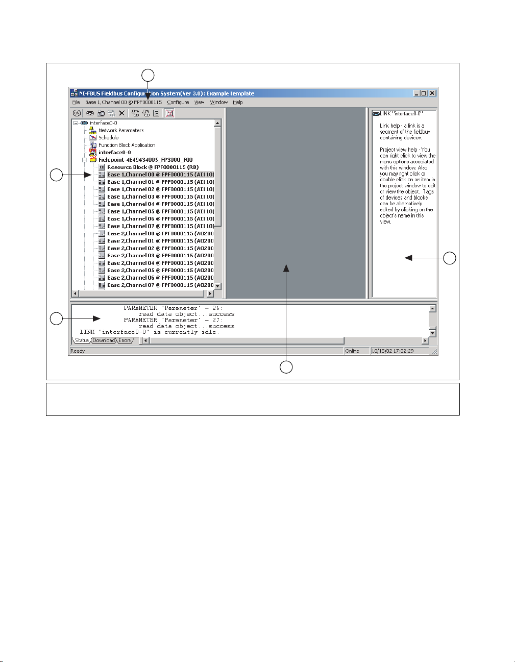
Configurator main window are shown in the following figure.
© National Instruments Corporation 1-1 NI-FBUS Configurator User Manual
Page 14
Chapter 1 NI-FBUS Configurator Overview
1
2
3
5
4
1 Object Menu (changes based on object
selected in configuration tree)
2 Configuration Tree
3 Status Window
4 Middle Frame
5 Help Window
At the upper-right corner of the screen, you may see two sets of resize
buttons. The outer set of buttons controls the NI-FBUS Configurator,
and the inner set controls whatever window is currently active in the middle
frame. To see other windows in the middle frame, you may need to
minimize the active window in the middle frame.
Configuration Tree
The configuration tree, which appears to the left of the middle frame,
displays the configurable objects of the link(s) connected to the
NI-FBUS Configurator. When you select an object in the configuration
tree, its own menu appears as the main menu bar Object menu item. You
also can view the items on this menu by right-clicking the object.
NI-FBUS Configurator User Manual 1-2 ni.com
Page 15
Note It is normal for objects to go invalid briefly during the initial bus scan or when
changing the device address. This is because the device suspends communication while
setting the address.
Help Window
Chapter 1 NI-FBUS Configurator Overview
To configure or view an object settings, double-click its icon in the
configuration tree.
You can click the Show/Hide Transducers and Device IDs button to
toggle between showing or hiding the transducer blocks and device IDs in
the configuration tree.
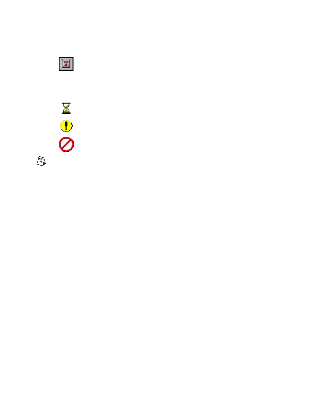
During the initial bus scan, the following state icons sometimes overlap the
configuration tree icons:
• Updating—This icon appears when the NI-FBUS Configurator is
reading or writing to the object.
• Error—This icon appears when the NI-FBUS Configurator detects or
encounters an error with the object.
• Invalid—This icon appears when the indicated object is not responding
to the NI-FBUS Configurator scan.
The help window, which appears to the right of the middle frame, displays
help information. To view help information for a particular topic, move the
mouse cursor over the relevant object or parameter. Some objects require
you to click the object to view the help. To toggle between showing or
hiding the help window, select Window»Help Window.
Status Window
The status window, which appears below the middle frame, displays the
current status of the NI-FBUS Configurator. The status window contains
three tabs. To toggle between showing or hiding the status window, select
Window»Status Window.
Status Tab
The Status tab shows live updates of what the NI-FBUS Configurator does
on the Fieldbus. The Status tab automatically appears on top when you
start the NI-FBUS Configurator. The Status tab displays the steps that the
NI-FBUS Configurator takes to accomplish a task when you read, write,
scan, or download data to the bus.
© National Instruments Corporation 1-3 NI-FBUS Configurator User Manual
Page 16

Chapter 1 NI-FBUS Configurator Overview
Download Tab
The Download tab shows all the status information for the last
configuration download to the bus. The NI-FBUS Configurator retains this
information until the next download. The Download tab automatically
appears on top when you begin to download your configuration. The status
information on the Download tab can also be read in the log/notes window.
The Download tab is updated only when a configuration is downloaded to
the bus.
Errors Tab
The Errors tab displays all recent I/O errors, project configuration errors,
and warnings in the current project. To fix an error, double-click the error
to open the window showing the cause of the error. For a list of possible
errors, refer to Appendix A, Error Messages and Warnings.
Use the drop-down list attached to the upper-left corner of the Errors tab
to filter the types of errors shown. The All Errors selection shows all I/O
and project errors, and the Project Errors selection shows only project
errors.
When you download your configuration, the NI-FBUS Configurator
checks for errors in your project. If you have a project error, the
NI-FBUS Configurator warns you and allows you to cancel the download.
The NI-FBUS Configurator automatically regenerates error information
each time you change the project. However, you can force the
NI-FBUS Configurator to revalidate the project by clicking the Check
Project for Errors toolbar button.
Middle Frame
The contents of the middle frame are determined by what you choose to
open there. Double-clicking certain items in the configuration tree causes a
corresponding window to open in the middle frame. The items in the
configuration tree that open a window in the middle frame are Function
Block Application, Schedule, Log/Notes, or any device.
Double-clicking a second item in the configuration tree opens another
window on top of the first window in the middle frame. To retrieve the first
window, you should minimize, restore, or close the second window using
the resize buttons shown in the following figure.
NI-FBUS Configurator User Manual 1-4 ni.com
Page 17
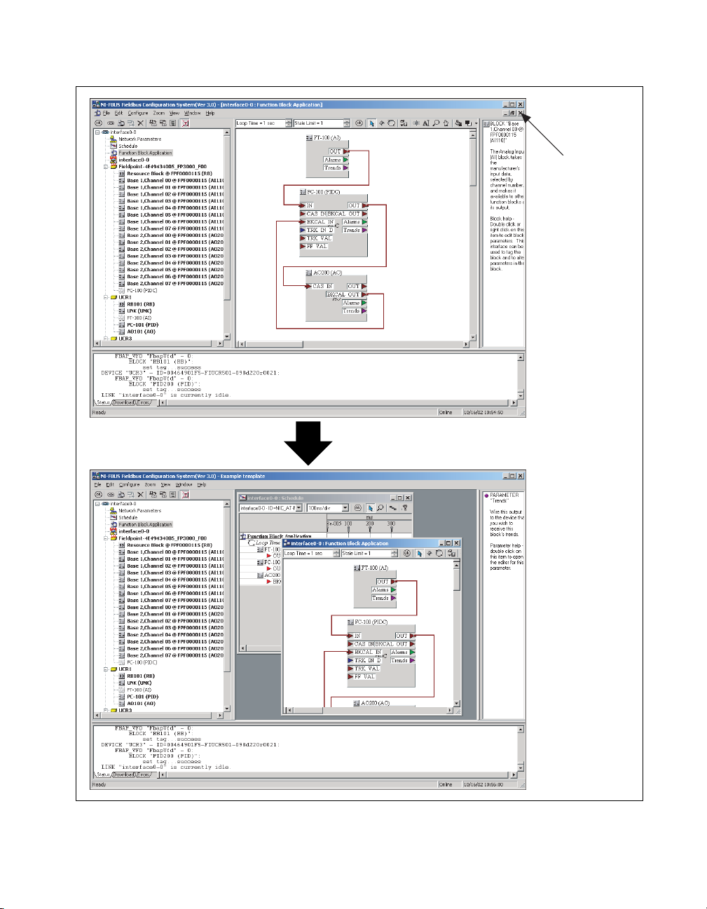
Chapter 1 NI-FBUS Configurator Overview
Use these
buttons to
view additional
windows
© National Instruments Corporation 1-5 NI-FBUS Configurator User Manual
Page 18

Chapter 1 NI-FBUS Configurator Overview
Function Block Application Editor Window
The Function Block Application Editor is the graphical interface you use to
create your Foundation Fieldbus control strategy (also known as the block
diagram) in the NI-FBUS Configurator.
You can open the Function Block Application Editor by double-clicking the
Function Block Application icon in the configuration tree. The Function
Block Application Editor appears in the middle frame of the NI-FBUS
Configurator. You can minimize and maximize this window using the
resize buttons in the upper-right corner. When this window is maximized,
the resize buttons appear under the main window resize buttons, above the
help window.
To connect blocks, use the Wiring tool. For help using this tool, refer to the
Wiring Blocks Manually section of Chapter 2, Using the NI-FBUS
Configurator.
To switch between the pointer, wiring, and loop tools in the Function Block
Application Editor window, press the <Tab> key. To switch between the
pointer and the wiring tool, press the spacebar.
You can drag and drop block or device icons from one window into another.
This is especially helpful when dragging function blocks from the
configuration tree into the Function Block Application Editor window.
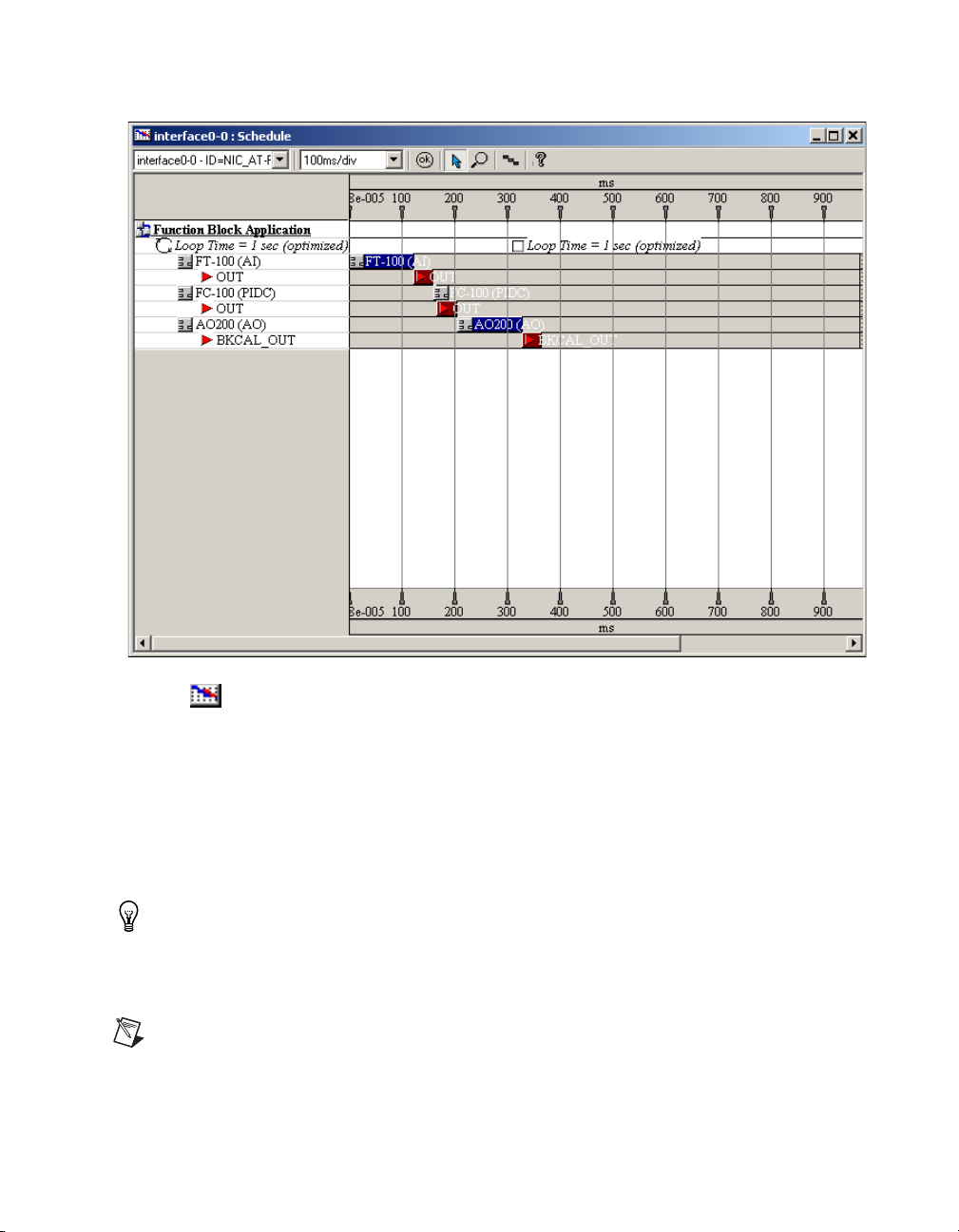
Schedule Window
The NI-FBUS Configurator combines the link active schedule and function
block schedules into one diagram, as shown in the following figure.
NI-FBUS Configurator User Manual 1-6 ni.com
Page 19
Chapter 1 NI-FBUS Configurator Overview
To view or edit the link active schedule, double-click the Schedule icon in
the configuration tree. The schedule window appears in the middle frame.
In the schedule window, a key to the scheduled objects appears on the left.
The timing diagram on the right displays the execution times of the function
blocks, and when data is transmitted on the bus. The blue bars on the screen
correspond to the function block execution times and the red bars
correspond to the data transmission times, which consist of LAS
notification time and transmission time.
Tip With only one device, you will not see data transmission since there are no parameters
that need to be transmitted to other devices. Also, for some fast devices (such as the
FP-3000), the blue block execution bars are so short that they are entirely hidden behind
the block icons themselves.
Note An optimized schedule can show that the transmission time overlaps the end of
function block execution. This is because the transmission time includes the time that the
LAS uses to tell the device to publish the data.
© National Instruments Corporation 1-7 NI-FBUS Configurator User Manual
Page 20
Chapter 1 NI-FBUS Configurator Overview
To change the execution time for a loop, click the execution time next to the
loop icon and type in the new time.
Device Window
The device window shows the device ID and address of the host device
or field device you select. From this window, you can view and change
advanced parameters. You can view the values in hex or decimal
representation.
You can open the device window in the following ways:
• Double-click the Host icon to open the device window for a host
device, which is the device that hosts the NI-FBUS Configurator
(the PC).
• Double-click the Device icon to open the device window for a field
device. The icon is followed by the device tag and its unique serial
identifier.
• Double-click the HSE/H1 Linking Device icon to open the device
window for a linking device. The icon is followed by the device tag and
its unique serial identifier.
Tip The Host device only occurs in the H1 segment, and the HSE/H1 Linking Device
only occurs in the HSE segment.
• This icon represents the H1 segment.
• This icon represents the HSE segment.
Network Parameters Window
The network parameters window lets you change the low-level (advanced)
configuration parameters for the link. To open the network parameters
window, double-click the Network Parameters icon in the configuration
tree. The network parameters window appears floating over the main
window.
Caution This feature is disabled in the HSE segment. Do not modify these parameters
without good reason. If you must modify parameters for certain devices, the device
manufacturer will recommend settings. Modifying these parameters can have an adverse
affect on data throughput rates. If settings are incorrectly modified, some devices may
disappear off the bus.
NI-FBUS Configurator User Manual 1-8 ni.com
Page 21
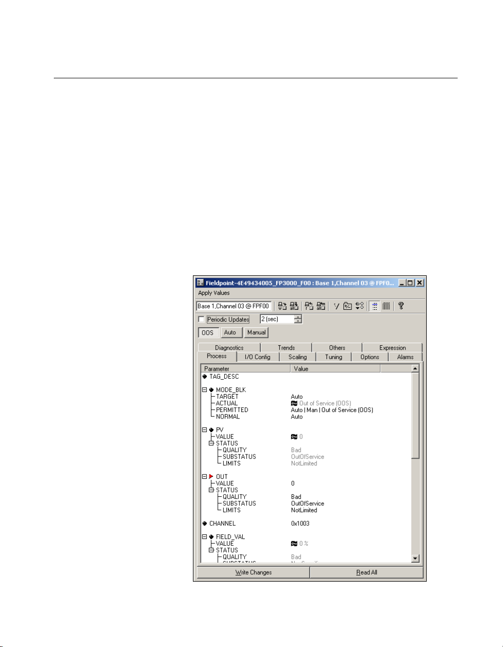
Block Configuration Window
Each function block in your application has a block configuration window
that you can use to change block parameters and other settings. When you
read or write data in the block configuration window, the Status tab in the
status window shows the status of the transactions.
To open the block configuration window for a block, do one of the
following:
• Double-click the name of the function block under the appropriate
device in the configuration tree.
• Double-click a function block in the Function Block Application
Editor window.
The block configuration window appears floating over the main window.
A block configuration window is shown in following figure.
Chapter 1 NI-FBUS Configurator Overview
© National Instruments Corporation 1-9 NI-FBUS Configurator User Manual
Page 22

Chapter 1 NI-FBUS Configurator Overview
Changing Parameter Settings
You can change parameter settings either by clicking the desired field and
typing the new value or by selecting the new value from a pull-down menu,
if provided. For more information, refer to the Editing Block Parameters
section of Chapter 2, Using the NI-FBUS Configurator.
Yellow highlighting in the block configuration window indicates that a
parameter setting has been changed and does not match the parameter value
stored in the device.
Block Configuration Window Icons
As shown in the previous figure, an icon to the left of each parameter name
color-codes and symbolically represents the class of the parameter.
Table 1-1 describes the classes of the parameters.
Table 1-1. Block Configuration Window Icons
Shape Color Description
Circle Green—Alarms Represents contained
Light blue—Tuning
Black—Others
parameters. Contained
parameters cannot be linked
to other parameters; they are
contained in the block.
Right arrow Red Represents output that can be
sent to another block.
Left arrow Blue Represents input that can be
obtained from another block.
Block Configuration Window Tabs
The block configuration window groups the parameters by functional
category. For example, parameters related to alarms appear on the
Alarms tab, and parameters related to tuning appear on the Tuning tab.
Uncategorized parameters appear on the Others tab. Some parameters
appear on multiple tabs. The tabs and their contents that you see will vary,
depending on the type of block you select.
You also can customize the tabs of the block configuration window. You
can add or delete tabs, change the order in which they appear in the window,
and add or remove any block parameters from an individual tab. For more
NI-FBUS Configurator User Manual 1-10 ni.com
Page 23

information, refer to the Categorizing Block Parameters section of
Chapter 2, Using the NI-FBUS Configurator.
Note When you customize a tab of the block configuration window, that customization
applies to all blocks of the same type, even in other projects.
Block Configuration Window Units
Some information in the block configuration window is presented in time,
however units are not explicitly shown. The units are 1/32 of a millisecond.
For example, if
736 by 32 to get the execution time of 23.8 milliseconds.
Execution Time is listed as 736, you should divide
Chapter 1 NI-FBUS Configurator Overview
© National Instruments Corporation 1-11 NI-FBUS Configurator User Manual
Page 24

Using the NI-FBUS Configurator
Start the NI-FBUS Configurator and NIFB Process
1. Install and configure your software and any Foundation Fieldbus
interfaces, as instructed in your getting started manual.
2. Install device descriptions, as instructed in your getting started manual.
3. Install and wire your Foundation Fieldbus device(s), as instructed in
the documentation that came with your device(s).
4. Select Start»Programs»National Instruments»NI-FBUS»
NI-FBUS Configurator to start the NI-FBUS Configurator and when
prompted, click Yes to start NIFB.EXE.
or
Select Start»Programs»National Instruments»NI-FBUS»
NI-FBUS Communication Manager to start the NIFB process,
then select Start»Programs»National Instruments»NI-FBUS»
NI-FBUS Configurator. Refer to your getting started manual for
more information about the NIFB process.
2
Create a New Project
1. When you start the NI-FBUS Configurator, the Start Up dialog box
appears automatically. If you want to create a new project at any other
time, select File»New.
Tip Close any open projects before opening or creating another. The multiple window
structure of the NI-FBUS Configurator quickly becomes confusing with multiple open
projects.
To hi d e the Start-up dialog box the next time you launch the NI-FBUS Configurator,
check Don't display this dialog again. To reveal the Start-up dialog box, select
Show New-Open Dialog at Start-up in the General page of the preferences dialog under
View»Preferences.
© National Instruments Corporation 2-1 NI-FBUS Configurator User Manual
Page 25
Chapter 2 Using the NI-FBUS Configurator
2. In the Start Up dialog box, each configured interface will appear.
Select the link(s) (ports on your Foundation Fieldbus interface) you
want to include in your project in the Added Link(s) checklist.
3. Select the type of project to create. Usually, this will be online.
4. Click OK.
The NI-FBUS Configurator scans the Foundation Fieldbus network and
checks addresses and object tags. If a device is missing either an address or
a tag, the NI-FBUS Configurator assigns one. If the NI-FBUS Configurator
detects duplicate tags, it renames the device or block, appending a numeric
identifier to the original device or block tag.
After you complete the preceding steps, the configuration tree appears,
displaying all the Fieldbus objects on the link or links you chose in step 3.
During the initial bus scan, the following state icons sometimes overlap the
configuration tree icons:
• Updating—This icon appears when the NI-FBUS Configurator is
reading or writing to the object.
• Error—This icon appears when the NI-FBUS Configurator detects or
encounters an error with the object.
• Invalid—This icon appears when the indicated object is not responding
to the NI-FBUS Configurator scan.
Note It is normal for objects to go invalid briefly during the initial bus scan or when
changing the device address. This is because the device suspends communication while
setting its address.
Open an Existing Project
To open an existing project, complete the following steps.
1. When you start the NI-FBUS Configurator, the Start Up dialog box
appears automatically. If you want to open an existing project at any
other time, select File»Open, browse to the file you want to edit, and
click Open.
2. In the Start-up dialog box, the recently accessed files appear in the
bottom listbox.
3. Select the Open an Existing Project option.
4. Choose the file item in the listbox, click the OK button, or double-click
the file item to open it directly.
NI-FBUS Configurator User Manual 2-2 ni.com
Page 26
5. To open other files, double-click More Files... in the listbox.
Upload Project Configuration
Using the Upload Project button (or selecting Configure»Upload
Configuration), you can cause the NI-FBUS Configurator to read a
configuration from a device that has already been configured and overwrite
the currently open project with that information. To prevent overwriting an
existing project, close all projects, then select File»New before uploading
a configuration. The function block parameters, schedules, linkages for
publisher/subscriber, alarms, and trends will be uploaded and placed in the
project. Note that the LAS schedule is not uploaded. The LAS schedule will
be created from the list of linkages and function block schedules by the
NI-FBUS Configurator’s usual scheduling algorithm. When the upload is
complete, the project can be modified, saved, or downloaded just as if you
had created it manually.
Set Device Addresses
The NI-FBUS Configurator automatically attempts to set addresses for the
devices it detects. Information on manually setting device addresses is
provided in case you want to change the addresses assigned by the
NI-FBUS Configurator when the device is initially brought on the bus.
Chapter 2 Using the NI-FBUS Configurator
Note The HSE device disables this operation for its IP address, and the host device
disables this operation for its constant address. In addition, be aware that devices may
disappear off the bus while their addresses are being set.
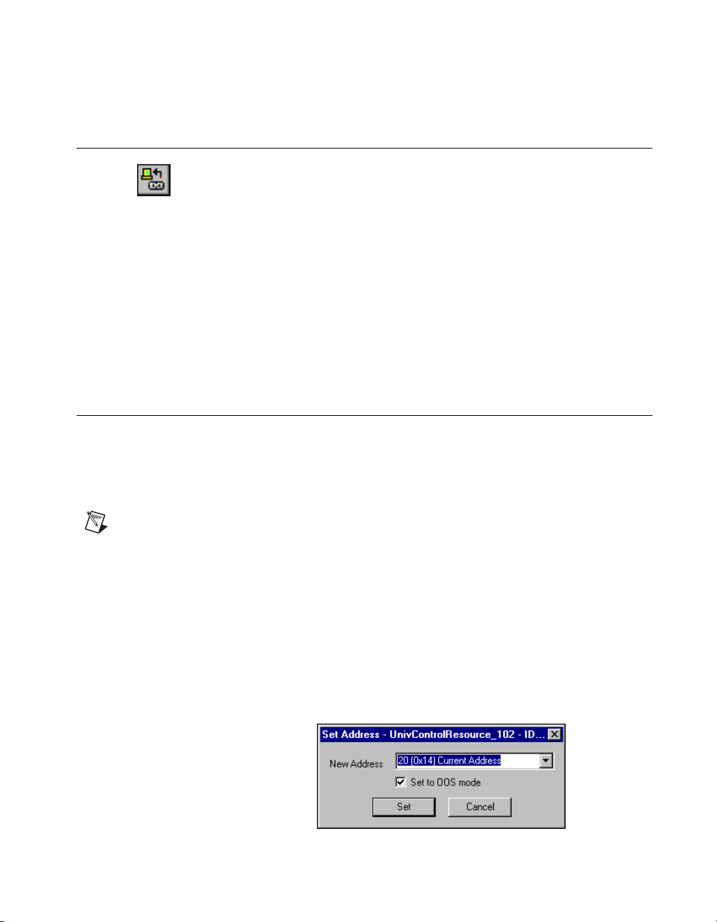
Complete the following steps to set the device address.
1. In the configuration tree, right-click the device whose address you
want to set and select Set Address. The Set Address dialog box
appears.
2. In the New Address field, select the desired address from the
drop-down list, as shown in the following figure.
© National Instruments Corporation 2-3 NI-FBUS Configurator User Manual
Page 27

Chapter 2 Using the NI-FBUS Configurator
3. Check the Set to OOS Mode checkbox. Doing so sets the block to out
of service (
current control system.
Caution When you set the device address, the device loses all linkage and
communication configuration information and loses control of the process. You should
not change a device address after you have configured and are running your process.
4. Click the Set button.
The NI-FBUS Configurator sets the device resource block to
mode before setting the new address. If the device does not go to
mode, the NI-FBUS Configurator notifies you and you must determine
whether to continue to set the address.
5. After you successfully set the address, you can set the resource block
to the desired mode.
If you need to expand the range of available addresses shown in the New
Address field, use the network parameters window to modify the number
of polled addresses.
OOS) mode, which prevents the device from operating in its
OOS
OOS
Function Block Instantiation and Deletion
The NI-FBUS Configurator detects whether a given device supports
function block instantiation (creation) and deletion. If a device supports
instantiation and deletion, Instantiate new block appears in the device
object menu. This menu can be accessed by right-clicking the device, or
from the menu bar when that device is selected. When you select
Instantiate new block, a dialog box appears that shows the available block
types for this device, as read from the device description. You may choose
the block type and the number of blocks of that type to instantiate. To delete
a block from a device which supports deletion, click in the block and press
the <Delete> key.
Note Most devices do not support instantiation and deletion of function blocks. For these
devices, all the available function blocks are pre-programmed and appear automatically in
the configuration tree under the device.
NI-FBUS Configurator User Manual 2-4 ni.com
Page 28
Set Device or Block Tags
Note If you have multiple host machines, setting a device or block tag may affect how
other host machines on an operating network access a device.
1. There are three ways to change a tag.
• In the configuration tree, right-click the device or block whose tag
you want to change and select Set Tag.
• Select the object menu item from the main menu bar and select
Set Tag.
• Double-click the device or block in the configuration tree to
launch the block configuration window. Then, click the Device
Tag field in the block configuration window.
2. In the New Tag field, type the tag you want to assign.
3. Make sure the Set to OOS Mode checkbox is selected.
Caution The host device does not permit this operation because it keeps in constant
communication. The HSE/H1 linking device also does not permit this operation because
it contains the H1 host device. Be aware that when you set the device tag, the device loses
all linkage and communication configuration information and loses control of the process.
You should not change device tags after you have configured your process.
Chapter 2 Using the NI-FBUS Configurator
4. Click the Set button. The NI-FBUS Configurator sets the block or
device to
does not go to
OOS mode before setting the new tag. If the device or block
OOS mode, the NI-FBUS Configurator notifies you and
you must determine whether to continue to set the tag. You should not
try to set the tag without putting the device in
Note It may take a few minutes for the tag to set.
OOS mode.
5. After you successfully set the tag, double-click the block icon to
launch the block configuration window.
6. On the Process tab, change the block from
mode (usually
MODE_BLK parameter. For a description of modes, refer to the Function
Auto) by selecting the desired Target mode from the
OOS mode to a desired
Block Modes section.
© National Instruments Corporation 2-5 NI-FBUS Configurator User Manual
Page 29

Chapter 2 Using the NI-FBUS Configurator
Function Block Modes
The most common operational modes for function blocks on devices are
Automatic (
(
OOS).
• In Automatic mode, the block is running under its normal automatic
control, using a local setpoint value in the normal block algorithm to
determine the output value.
• In Cascade mode, the block is receiving its setpoint value from another
function block for use in the normal block algorithm to determine the
output value. A linkage object makes the connection between the two
blocks. The linkage object is created implicitly when you wire the
output of one function block to the input of another as described in the
Create and Edit Function Block Applications section. For example,
a PID function block receives its setpoints from an upstream block.
• In Out Of Service mode, the block is not running at all. Normally, this
mode is used during block configuration. Some devices require that the
function block be in Out Of Service mode when changing certain
parameters.
• In Manual mode, the block output is not being calculated by the normal
block algorithm. The operator writes the output of the block directly.
Auto), Cascade (Cas), Manual (Man), and Out Of Service
The MODE_BLK Parameter
The MODE_BLK parameter for a function block is the parameter that
contains information on the modes of the block. It has four fields:
ACTUAL, PERMITTED, and NORMAL. PERMITTED and NORMAL are defined
by the device manufacturer.
•
PERMITTED contains a list of all allowable modes for that block.
•
NORMAL is the mode the device manufacturer expects the block to be
in during normal operation.
•
ACTUAL is the current operating mode of the function block on the
device.
•
TARGET is a field that is writable by the user. Writing this field tells the
device to change to the specified mode. The device will attempt to
change the mode. If it is successful, the
reflect the
NI-FBUS Configurator User Manual 2-6 ni.com
TARGET mode.
ACTUAL mode changes to
TARGET,
Page 30
Note If the block is not currently scheduled, it will always remain in OOS mode, regardless
of any writes to the
Application Editor window and downloading the project to the device. Refer to the Add
Blocks to the Function Block Application section and the Download a Project
Configuration section for more information.
TARGET field. A block is scheduled by placing it in a Function Block
For more information on all the allowable modes, refer to the MODE_BLK
(Diagnostic, Process) parameter description of Chapter 4, Parameters.
Configure Block Parameters
Categorizing Block Parameters
The NI-FBUS Configurator lets you customize the parameter
categorization. You can add or delete custom tabs on the block
configuration window.
All custom changes that you make will be saved on this computer, and
associated with this block type, so all blocks of this type in all projects will
use your custom setup.
Chapter 2 Using the NI-FBUS Configurator
If you do not want to change the default categorization, skip to the Editing
Block Parameters section.
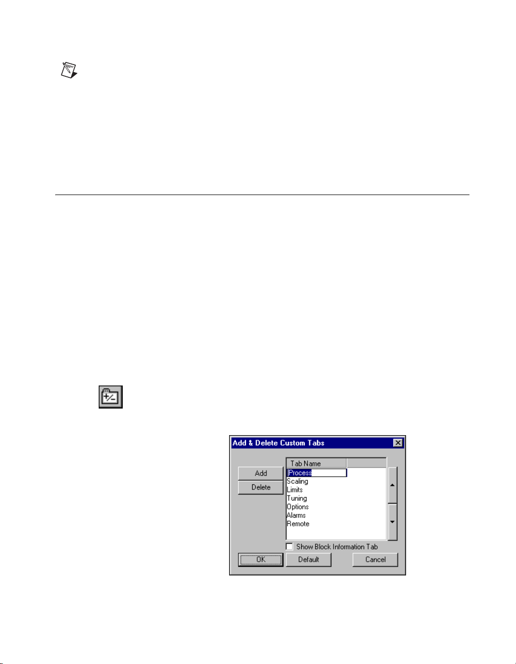
Adding Tabs
1. Click the Add or Delete Custom Tab button in the block
configuration window toolbar. The Add & Delete Custom Tabs
dialog box appears.
2. Click the section where you want to add the tab.
© National Instruments Corporation 2-7 NI-FBUS Configurator User Manual
Page 31

Chapter 2 Using the NI-FBUS Configurator
3. Click the Add button. Click the newly created blank field and type the
name of the new tab.
4. The Block Information tab contains additional read-only information
on each block, such as execution time. Checking the Show Block
Information Tab checkbox will add this tab to your view.
5. Click the OK button to generate the new tab.
On the new tab in the block configuration window, right-click and
select Customize Parameters. Follow the steps in the Customizing
Parameters on a Tab section to configure the parameters for your
new tab.
Customizing Parameters on a Tab
You can customize parameters on a tab by using the Customize
Parameters button. Check the boxes next to the parameters you want
to show on this tab, or uncheck the boxes to remove the parameters from
this tab.
Removing Tabs
To remove a tab from the block configuration window, complete the
following steps:
1. Click the Add or Delete Custom Tab button in the block
configuration window toolbar. The Add & Delete Custom Tabs
dialog box appears.
2. In the Add & Delete Custom Tabs dialog box, click the name of the
tab that you want to remove.
3. Click the Delete button.
4. Click OK.
Modify Block Configuration Window View
You may need to resize the block configuration window to view all buttons
and parameters.
To update the screen, click the Simple Verify button. In the dialog box that
appears, click Verify, then click Done.
To add space between parameter listings, click the Spaced View button.
NI-FBUS Configurator User Manual 2-8 ni.com
Page 32

To display the Parameter, Va lu e, Type & Range, and Help columns, click
the Detailed View button. To return to displaying only the Parameter and
Val ue columns, click the Detailed View button again.
Editing Block Parameters
The default tab groupings in the block configuration window are by
functions. Parameters with a plus sign beside them are records or arrays
(structures) that contain more than one entry. To expand the record or array,
click the plus sign, or to collapse the structure, click the minus sign. The
sub-elements of a record are called fields.
The drop-down box for editing enumerated types on blocks is sized
according to the width of the Value column. You may need to resize the
Value column to view the entire entry in a drop-down box.
Chapter 4, Parameters, includes complete descriptions of the parameters
and their values.
To edit a block parameter value, complete the following steps:
1. Double-click in a function block to open the block configuration
window.
2. By default, records are expanded. If for some reason they are
collapsed, click the plus sign to see the values of the record or array
parameters.
3. Use the cursor to select the parameter value you want to change.
In many cases, you can select the desired setting from a drop-down
menu, or type in the new value. If a parameter value is grayed out,
it is read-only and you cannot change it. After you change a parameter
value, an asterisk (*) appears by the parameter name and the field turns
yellow.
4. To make your changes effective immediately, click the Write changes
button on the block configuration window toolbar. If the device accepts
the new setting, the asterisk and yellow color will clear. If the device
does not accept the new setting, you are probably trying to write a
setting that is invalid for your device. Refer to the help information for
that parameter or your device documentation to identify valid settings.
Chapter 2 Using the NI-FBUS Configurator
Tip If you decide that you do not want to write the changed value to the device, you can
undo your change to the block configuration window by reading the parameter value stored
in the device as described in the Manually Update Block Parameters section.
© National Instruments Corporation 2-9 NI-FBUS Configurator User Manual
Page 33

Chapter 2 Using the NI-FBUS Configurator
5. If you do not click the Write changes button, you can make all your
changes take effect when downloading the configuration by checking
the Write Contained Block Parameters checkbox.
You also can click the Write All button to write all parameters, including
changed block tags, to the block on the device.
Note Some devices will require that you set their mode to OOS mode before writing certain
parameters. A dialog box will appear to inform you of this if you attempt to write such a
parameter in any other mode.
Updating Block Parameters Values
You can update block parameter values in the block configuration window
manually or automatically, as described in the following sections.
Manually Update Block Parameters
To update one particular block parameter value manually, select the
parameter and click the Read Selected button in the block configuration
window toolbar.
To update all the block parameter values, click the Read All button.
Automatically Update Block Parameters
To set the NI-FBUS Configurator to update the block parameter values
periodically, complete the following steps:
1. At the top of the block configuration window, check the Periodic
Updates checkbox. When this box is checked, the NI-FBUS
Configurator periodically checks the bus for any changes in values for
the parameters and refreshes the values in the window.
An icon at the upper-left corner of the block configuration window
blinks green when you select the Periodic Updates checkbox.
2. Select the poll rate from the drop-down list next to the Periodic
Updates checkbox. The NI-FBUS Configurator will update all block
parameter values at that rate.
3. An icon at the upper-left corner of the block configuration window
blinks green to indicate you selected Periodic Updates.
Note If you select a fast update rate, the reads from the bus might not be able to occur at
that rate due to bus traffic, especially if you are already running a process.
NI-FBUS Configurator User Manual 2-10 ni.com
Page 34

Chapter 2 Using the NI-FBUS Configurator
Create and Edit Function Block Applications
Function blocks contain an algorithm and multiple parameters to control a
process. The names of input and output parameters of a function block are
displayed on the block diagram, as shown in the following figure.
The pointers on the outside of the parameters show the data flow direction
of that parameter. By default, the block tag is at the top, the inputs are on
the left, and the outputs are on the right.
You can resize the block and move the block’s tag relative to the block.
Add Blocks to the Function Block Application
1. To open the Function Block Application Editor window, double-click
the Function Block Application icon in the configuration tree.
2. Drag blocks from the configuration tree to the Function Block
Application Editor until all the blocks you want to use are in the
Function Block Application Editor.
Tip You can drag host devices from the configuration tree into the Function Block
Application Editor. Dragging host devices allows you to configure alarms and trends,
as described in the Configuring Alarms section and the Configuring Trends section.
You also can add blocks by completing the following steps.
1. Right-click in the background of the Function Block Application
Editor or click the Block button in the toolbar of the Function Block
Application Editor.
2. Select the device or interface from the menu that appears, and then
select the block you want to place on the screen from the menu of
function blocks.
© National Instruments Corporation 2-11 NI-FBUS Configurator User Manual
Page 35

Chapter 2 Using the NI-FBUS Configurator
Note You can use a function block in a Function Block Application Editor window only
once. After the block has been dragged over, it will be grayed out on the menu and in the
configuration tree. To use one block’s output as inputs to multiple downstream blocks, wire
the output to both locations. To use one block’s output in multiple loops, refer to the
Defining Loops section.
The following figure shows how the Function Block Application Editor
looks with function blocks dragged onto it.
Connecting Blocks
To send data from one block to another, you must connect the outputs and
inputs. You can wire blocks manually or use a template. The help window
on the right side of the screen describes the input and output parameters and
how they can be connected.
All the necessary arrangements for broadcasting data over the bus are
automatically generated when you wire the function blocks together.
When you later download your project to the bus, this scheduling and
linkage information will be downloaded to all the link masters on the link.
Wiring Blocks Manually
To wire blocks manually, complete the following steps:
1. Click the Wiring tool on the Function Block Application Editor
toolbar.
2. Click one terminal you want to connect.
NI-FBUS Configurator User Manual 2-12 ni.com
Page 36

Chapter 2 Using the NI-FBUS Configurator
Tip You do not have to connect points in any particular order. You can start at the input
and wire to the output, or vice-versa.
3. To tack down the wire at different points, click in the background of
the Function Block Application Editor window.
Tip To toggle the direction of the connection you are dragging, press the spacebar
while wiring.
Tip To zoom in and out, click the magnifying glass icon. To zoom in, drag a rectangle
around the area you want to enlarge. To zoom out, right-click the background of the
Function Block Application Editor window. You also can select different zoom settings
from the Zoom menu.
4. Click the terminal to which you want to wire.
When you click the Wiring tool, the NI-FBUS Configurator performs type
checking and highlights valid inputs and outputs when you move the cursor
over them. For instance, it will not allow you to wire an analog output to a
discrete input.
The following figure shows the
wired to the
BKCAL IN input of the PID block.
BKCAL OUT output of the AO block being
© National Instruments Corporation 2-13 NI-FBUS Configurator User Manual
Page 37

Chapter 2 Using the NI-FBUS Configurator
Checking for Function Block Application Errors
Click the Check Project for Errors button in the Function Block
Application Editor window to perform error checking, regenerate the
schedule of the application, and remove bad wires.
Customizing Your Function Block Application
Click the Text button to type additional information about the application
and change text in fields.
Click the Fill button to fill objects on the screen with a color.
Click the Fill Color button to select a color to be used with the Fill tool.
Using Templates
Templates are pre-defined, pre-wired control loops that you can drop into
the Function Block Application Editor to use as a model for your function
block application. Templates can help you by providing the wiring for
common control strategies, such as PID loops. You also can create your
own templates to reduce time required for configuring multiple “copies” of
your own strategies.
Tip Templates store parameter values as well as wiring connections, saving you the
time-consuming operation of configuring function block parameters when you have
multiple copies of the same type of control strategy.
The NI-FBUS Configurator includes the following templates:
• PID Feedback Control
• Manual Control with PV Indication
• PD Feedback Control
• Track Feedforward Control
• Cascade Control
• Ratio Control
•Override Control
National Instruments-defined templates are provided for wiring use only;
the values in those templates will be overridden by your function block
settings. The values stored in user-defined templates will be applied or
not applied, at your discretion, when you use the template. It is not
NI-FBUS Configurator User Manual 2-14 ni.com
Page 38

Chapter 2 Using the NI-FBUS Configurator
recommended that you accept the template values for templates you did not
create; the parameter settings may not be appropriate for your device(s).
Inserting Templates
To access templates, do one of the following:
• Right-click the background of the Function Block Application Editor
and select the desired template from FBAP Templates.
• Select File»Open Template.
A dialog box appears asking how to apply the template parameter values to
the function block that will eventually replace the template. You can choose
one of four different options:
• Click the No button to keep the function block’s current values. This
will ignore any values stored in the template. If you did not create this
template with parameter setting appropriate for the device(s) you plan
to use in it, this is the appropriate option.
• Uncheck the Use Template CHANNEL values? checkbox and click
the Yes, use values button to change the parameter values of the
function blocks used to fill the template to match the template
parameters (except the
set up a PID loop for one set of input and output devices and would like
to use the same loop with the same settings for other sets of identical
input and output devices. In this case, you would save your initial PID
loop as a template. Then, you would insert the template, uncheck the
Use Template CHANNEL values? checkbox, and choose Yes, use
values.
In this case, any function block used to fill the template will take on the
saved parameters, except it will keep its own
(that is, device input or output channel that is set to control). Refer to
the Creating Templates section for more information on creating
templates.
• Check the Use Template CHANNEL values? checkbox and choose
Yes, use values to change the function block parameter values to
match all the template parameters, including the
• Click the Decide Later button to do nothing now, but ask the same
question for each individual function block when you actually fill the
template.
CHANNEL parameter). This is useful if you have
CHANNEL parameters
CHANNEL parameters.
Tip If you select the Decide Later option, you can later browse the template parameter
values by right-clicking the template block outline and choosing Open, or by
double-clicking the block.
© National Instruments Corporation 2-15 NI-FBUS Configurator User Manual
Page 39

Chapter 2 Using the NI-FBUS Configurator
While the template is highlighted in the Function Block Application Editor,
you can drag it to the desired location.
Tip Moving the mouse just outside of the Function Block Application Editor window
while dragging blocks will cause it to scroll.
An example of a template, both when initially placed and when filled, is
shown in the following figure. The template on the left illustrates how a
template appears when initially placed, and the template on the right
illustrates how it looks after it has been filled in.
NI-FBUS Configurator User Manual 2-16 ni.com
Page 40

Chapter 2 Using the NI-FBUS Configurator
When templates are initially placed, the template blocks are grayed out.
This is because you have not assigned a function block to the template
block. To assign a function block to the template block, complete the
following steps:
1. Double-click the template block to view all the blocks that match this
block type in your project.
2. Select the desired block from the list that appears.
You must replace all the template blocks with function blocks from your
project. The Errors tab lists errors warning you of unassigned templates.
Creating Templates
After you have set up the function block parameters and connections for the
first unit, you can save that setup as a template for later use. If you want to
save only part of your function block application as a template, select that
part (drag the pointer around the desired blocks and wires OR use the
Control key while clicking the desired blocks and wires). With the Function
Block Application Editor window open, select File»Save Template. You
can choose to save only selected items or the entire Function Block
Application. By default, the NI-FBUS Configurator saves all templates in
the
\fcs\templates directory under your installation of NI-FBUS. If a
template is in that directory, it automatically appears as an available
template in the template menu.
Export Function Block Application Image
You can export the image of configured function block application
as a bitmap file.With the Function Block Application Editor window open,
select File»Export Fbap Image.
Defining Loops
A loop is a group of connected function blocks that execute at a specified
rate. You can define multiple loops in one Function Block Application.
The following figure shows an example of two separate loops running at the
same rate. Loops running at the same rate can be placed in a Function Block
Application without using a loop structure.
© National Instruments Corporation 2-17 NI-FBUS Configurator User Manual
Page 41

Chapter 2 Using the NI-FBUS Configurator
Defining Multiple Loops Running at Different Rates
The loop execution time shown on the Function Block Application Editor
toolbar is the default execution time for all function blocks on the window
not isolated in a loop structure. You can use the loop structure to isolate a
group of function blocks to run at a different execution rate than the rate on
the Function Block Application Editor toolbar.
For example, in the following figure, the AI and PID blocks to the left are
one loop and execute at a rate of once every second, as shown in the toolbar.
The AI-PID-AO loop to the right executes once every 500 ms, as shown at
the top of the loop structure.
NI-FBUS Configurator User Manual 2-18 ni.com
Page 42

Chapter 2 Using the NI-FBUS Configurator
To create a loop structure, complete the following steps:
1. Click the Loop tool on the Function Block Application Editor toolbar.
2. Click the desired location for one corner of the loop and drag the loop
around the blocks you want to include in the loop.
3. To change the loop execution time, double-click the box at the upper
left of the loop, and type the new time.
© National Instruments Corporation 2-19 NI-FBUS Configurator User Manual
Page 43

Chapter 2 Using the NI-FBUS Configurator
Determining Function Block Execution Time
Because function blocks must execute serially, there is a trade-off between
how many PID loops you can run and how fast you can run them. The
maximum execution time for each block (that is, the worst-case execution
time) is specified by the device manufacturer. To view the maximum
execution time for a block, complete the following steps.
1. If you have not already done so, select View»Preferences and click
the Block View tab.
2. Select the Show Block Information checkbox, and click OK.
Now when you double-click on a function block, a new tab called
Block Information will appear.
Look at the parameter
for the function block. If the number is a hexadecimal number, you can
change it to decimal by right-clicking and unchecking Hexadecimal Data.
The decimal value of this parameter is the execution time in 1/32 ms,
as required by the Foundation Fieldbus specification (that is, dividing this
number by 32 will give the maximum execution time, in milliseconds).
For example, the maximum execution time for a National Instruments
FP-3000 AI-110 block (with firmware revision 2) is listed as 192. Dividing
this by 32 gives 6 ms maximum execution time.
Changing the Block Execution Order
To change the execution order of the blocks, complete the following steps:
1. In the Function Block Application Editor, click the Execution Order
button. Numbers appear on the blocks, indicating their current order,
as shown in the following figure.
EXECUTION_TIME on the Block Information tab
NI-FBUS Configurator User Manual 2-20 ni.com
Page 44

Chapter 2 Using the NI-FBUS Configurator
2. Click the blocks in the order that you want them to execute.
3. When you are done, click in the background of the Function Block
Application Editor or select another tool. The change will be reflected
in the schedule. For more information, refer to the View and Edit a
Schedule section.
Setting the Stale Limit
Click the Stale Limit field to adjust the number of consecutive duplicate
values that a function block accepts before it labels the input data as stale
(old data).
© National Instruments Corporation 2-21 NI-FBUS Configurator User Manual
Page 45

Chapter 2 Using the NI-FBUS Configurator
Using Menus and Methods
The NI-FBUS Configurator supports user methods, which are a sub-set of
the Foundation Fieldbus Menus and Methods specification.
User methods are the methods you explicitly invoke from the NI-FBUS
Configurator. Typically this would be a method that is called “Set up
device” or “Calibrate valve”—something that represents a specific task you
want to perform.
If you double-click a function block in the configuration tree and the block
has menus and methods associated with it, a menu bar appears above the
block configuration window toolbar and the Methods tab appears in the
block configuration window.
The first menu item in the block configuration window is normally Apply
values, which shows up for all blocks. Any additional menus defined by the
device description will appear to the right of this menu. These menus can
contain parameter names or the names of methods, which can be invoked
by selecting them. If there are any methods detected in the device
description that are not already on a menu, a menu titled
shown, with an entry for each method.
Methods will be
If you select a parameter name from the menu, an edit window for that
parameter will appear. To invoke a method, select it from the menu bar.
The block configuration window will switch to the Methods tab, which
displays all output from the method. In addition, when the method requires
you to enter input, you will be prompted to type it in a box in the Methods
tab. Methods will run until they encounter an error or complete. Error
information is also displayed in the Methods tab. You cannot close the
block configuration window while a method is still running.
Configuring Alarms
You can configure a device, such as an interface in a PC, to receive alarms
generated by function blocks.
1. Drag the configuration tree icon for the device or interface to which
you want to send the alarm to the Function Block Application Editor,
if you have not done so already.
2. Either wire the Alarms output of the block that you want to generate
an alarm to the device you want to receive the alarm, or check the
Receive All Alarms box, if the device has one. The following figure
shows an example of a configured alarm.
NI-FBUS Configurator User Manual 2-22 ni.com
Page 46

3. Double-click the function block that you want to generate the alarm.
The block configuration window appears.
4. In the block configuration window, click the Alarms tab to view or
change alarm information, such as the high and low limits of an alarm
condition, alarm priorities, and so on.
Configuring Trends
You can configure a device, such as an interface in a PC, to receive trends
from function blocks.
1. Drag the configuration tree icon for the device or interface to which
you want to send the trend to the Function Block Application Editor,
if you have not done so already.
2. Either wire the Tre nd s output of the block to the device you want to
receive the trend, or check the Receive All Trends box, if the device
has one. The following figure shows an example of a configured trend.
Chapter 2 Using the NI-FBUS Configurator
3. Double-click the function block from which you want to send a trend.
The block configuration window appears.
4. In the block configuration window, click the Trends tab.
5. Check the Tre nd column checkbox next to the parameter you want
to trend.
© National Instruments Corporation 2-23 NI-FBUS Configurator User Manual
Page 47

Chapter 2 Using the NI-FBUS Configurator
6. Set the sample Interval of the trend in loops/sample. The interval
should be a multiple of any loop macrocycle time in which this block
is involved. For example, if the interval is 2 loops/sample, and the loop
macrocycle time is 1 s, the trend will acquire a value every 2 s.
7. Set the Sample Type. Select Instant or Average from the Sample
Type drop-down list. Instant trends the actual value. Average trends
all samples.
Note If you want to view trends on a host computer, that computer must have software.
The NI-FBUS Configurator does not have trend-viewing functionality.
View and Edit a Schedule
The NI-FBUS Configurator automatically determines the execution order
and timing of the schedule based on your control strategy, network and
device factors, and the loop execution rate you choose. The NI-FBUS
Configurator also automatically optimizes the schedule.
The Link Active Scheduler (LAS) is a device that dictates both scheduled
and unscheduled communication according to the schedule downloaded to
it. The Primary LAS field on the schedule window displays the name of
the device that is the primary LAS for the system.
Change the Link Active Schedule
You can change the schedule by completing the following steps:
1. Double-click the Schedule icon in the configuration tree.
The schedule window appears.
2. Click the Scale field to display or change the time and divisions on the
timing diagram.
3. Use the cursor to drag the function blocks in the schedule as desired.
Dragging bars in the schedule shuts off the automatic optimization.
If you want to reoptimize, click the Optimize Schedule button on the
schedule window toolbar.
4. During the time between scheduled and unscheduled communications,
the LAS allows unscheduled communications to occur. Unscheduled
communications are always secondary to scheduled communications.
The ratio of scheduled to unscheduled time can have an affect on data
throughput rates.
5. To verify the schedule, click the Errors button in the schedule window.
NI-FBUS Configurator User Manual 2-24 ni.com
Page 48

Tip To zoom in and out, click the magnifying glass icon in the schedule window.
Tip With only one device, you will not see data transmission since there are no parameters
that need to be transmitted to other devices. Also, for some fast devices (such as the
FP-3000), the blue blocks representing execution times are so short that they are entirely
hidden behind the block icons.
Note An optimized schedule can show that the transmission time overlaps the end time
for the function block because the transmission time includes the time that the LAS uses
to tell the device to send the data.
Multiple Loop Representation
The following figure shows how the NI-FBUS Configurator displays
multiple loops in the schedule window.
Chapter 2 Using the NI-FBUS Configurator
The loops are separated by white dividers. If you would like to lock the
current schedule for a given loop, check the Loop Time checkbox shown
above the colored bars. This will prevent you and the NI-FBUS
Configurator from changing the schedule until you uncheck the box.
© National Instruments Corporation 2-25 NI-FBUS Configurator User Manual
Page 49

Chapter 2 Using the NI-FBUS Configurator
Set Network Parameters
To change network parameters such as the Link Active Scheduler (LAS)
and primary time master, double-click the Network Parameters icon in
the configuration tree.
The Network Parameters dialog box appears. This dialog box lists all
devices capable of being link master for the link. Every device you select
in this dialog box receives the Link Active Schedule when you download
your configuration. Thus, if the primary LAS is unavailable, one of these
devices will step in and continue executing the Link Active Schedule.
This is how the Foundation Fieldbus implements redundancy.
Advanced link settings control the interaction of devices over the network.
They are set on a port-by-port basis.
Caution This feature is disabled in the HSE segment. Do not modify advanced parameters
without good reason. If you must modify parameters for certain devices, the device
manufacturer will recommend settings. Modifying these parameters can have an adverse
affect on data throughput rates. If settings are incorrectly modified, some devices may
disappear off the bus.
To revert to the default network parameters, double-click Network
Parameters. Click the Link Settings tab. Press the Press to See Suggested
Values pushbutton. The next window shows the original settings.
Change Language
At the device manufacturer’s discretion, names and help strings can be
provided in multiple languages.
1. Select View»Preferences»General tab.
2. In the DD Language Codes field, enter the ISO standard two-letter
language abbreviation.
Save a Project Configuration
To save a configuration, select File»Save. This saves the entire project,
including the configuration tree, Function Block Application, schedule,
and notes/log.
NI-FBUS Configurator User Manual 2-26 ni.com
Page 50

Download a Project Configuration
Up to this point, the only information sent to the devices has been the
parameters written from the block information window. Before function
blocks will execute on the device, the rest of the configuration must be
downloaded to the devices. Function block linkages must be downloaded
to allow dataflow from one block to another. Also, the schedules for
function block execution and communication have not yet been provided to
the devices. When you download a configuration, the NI-FBUS
Configurator sends the following information over the bus:
• Communication schedule for the LAS
• Function block execution schedule for devices
• Function block linkages
• Alarm configuration
• Trend configuration
• Static parameters
Complete the following steps to download your project configuration.
1. Click the Download Project button in the configuration tree toolbar or
select Configure»Download Configuration. The Download
Configuration dialog box appears.
2. Select the configuration object to download.
3. If you have not done so already, click the Link Masters button to set
link masters to receive the primary Link Active Scheduler, the primary
time master of the link, and the Link Active Schedule. The Network
Parameters dialog box appears.
4. (Optional) Check the appropriate checkboxes for the download
options. Refer to the Download Options section for more information.
In general, you should use Clear Devices and Automatic Mode
Handling on all downloads.
5. To download your configuration changes to the network, click the
Download button. The Download Status progress bar shows what
percentage of the configuration is complete.
While downloading, the NI-FBUS Configurator displays and updates
the Download tab in the status window. It shows what device is
currently being configured, its settings, and whether it was
successfully configured.
6. If you did not check the Automatic Mode Handling checkbox, click
the Set All Targets to OOS button to switch the function blocks to
Chapter 2 Using the NI-FBUS Configurator
© National Instruments Corporation 2-27 NI-FBUS Configurator User Manual
Page 51

Chapter 2 Using the NI-FBUS Configurator
OOS mode. After the configuration downloads, you must set the blocks
back to their normal mode of operation to begin operating.
Download Options
There are several options in the download configuration dialog box for
downloading a configuration.
Write Contained Block Parameters
Write Contained Block Parameters writes all contained parameters
(parameters that are internal to the function block, such as the scaling
and alarm limit settings) from the block configuration windows. This is
especially useful if you are changing parameters in multiple function
blocks and do not want to take the time to write them block by block.
Note Per the Foundation Fieldbus specification, some contained parameters have default
values that are not legal values. This is done to encourage users to change these parameters
to values appropriate for their process. Often, device manufacturers will allow their devices
to operate with uninitialized parameter values, but any attempts to rewrite the uninitialized
value to a parameter will result in an error. As a result, using Write Contained Block
Parameters generates errors if any parameters are left uninitialized. Such errors can be
cleared by writing a legal value to the parameter or by reading into the NI-FBUS
Configurator the value from the device. Generally, such errors are non-fatal and the
download can continue successfully.
Clear Devices
Clear Devices clears the existing configuration in the devices before
downloading. It is good practice to use this option. Using this feature
ensures that the linkages you see in the Function Block Application Editor
window are the only linkages in the device. Otherwise, linkages from a
previous download may persist.
Automatic Mode Handling
Automatic Mode Handling automatically takes the blocks OOS as needed
during the download process and returns them to their normal modes of
operations (as read from
configuration is downloaded. This is a time-saving and convenience
feature. If this option is not checked, you will be prompted to take the
blocks to
after the download completes.
NI-FBUS Configurator User Manual 2-28 ni.com
OOS as needed and will have to set them back to NORMAL by hand
MODE_BLK.NORMAL for each block) after the
Page 52

If you do not select Automatic Mode Handling, the NI-FBUS
Configurator shows a table of all the block modes at the start of
configuration. You have the ability to change any of the modes from this
table, or to set them all to
The table appears again at the end of configuration, and allows you to set
the modes by hand, or click the Set All to Normal button to put all the
blocks into their normal modes. Note that the modes you have selected will
not be written to the bus until you click the Continue button.
Verify and Diff
This option causes the NI-FBUS Configurator to upload the actual
configuration from the devices after a download. It will then compare
the uploaded information to the configuration file in the NI-FBUS
Configurator. Refer to the Compare Two Configurations section for
instructions. This will report any differences between the configuration file
and the actual configuration of the devices. It is useful to compare a
configuration file to the bus in cases that the exact configuration on the bus
is unknown or to verify that the devices accepted all assignments.
Bringing a Block Online
If you did not select Automatic Mode Handling during the download
process, you will have to manually change the function blocks back to their
normal mode of operation.
1. Go to the
TARGET to Auto. Wait a few seconds and reread the MODE_BLK
parameter. The
the parameters on the Diagnostics tab to identify the problem.
2. Go to the
in and set the
3. Reread the
If it does not, examine the parameters on the Diagnostics tab
to identify the problem, or refer to your device documentation.
Chapter 2 Using the NI-FBUS Configurator
OOS using the Set All Targets to OOS button.
MODE_BLK parameter of the resource block and set the
ACTUAL field should go to Auto. If it does not, examine
MODE_BLK parameter of the function block you are interested
TARGET to Auto.
MODE_BLK parameter. The ACTUAL field should go to Auto.
Once the block goes to
© National Instruments Corporation 2-29 NI-FBUS Configurator User Manual
NORMAL mode, it is executing on the device.
Page 53

Chapter 2 Using the NI-FBUS Configurator
Monitoring Parameters
After downloading your configuration, you can display a graphical
representation of the updates to input, parameters, and mode parameters
of function blocks.
1. On the Function Block Application Editor toolbar, click the Monitor
button, or select Configure»Monitor. This option is available only
when the Function Block Application Editor is active.
2. In the monitor window, select the types of items you want the
NI-FBUS Configurator to monitor and display.
3. Modify the update rate as desired.
4. Click the Start Monitoring button to monitor the application.
The mode box for a block will be outlined in red if the actual mode for the
block does not match the target mode, which assists in quickly diagnosing
system problems.
Verify a Configuration
Quick Verification
You can perform a quick check to verify that the parameters on the bus
match those in the project for a particular link, device or function block.
1. Right-click the desired object in the configuration tree and select
Simple Verify Configuration.
2. Click the Verify button. The NI-FBUS Configurator compares the
project settings to the actual settings for the selected object and
displays the result in the Result field.
Caution Selecting Upload Changes modifies the currently open project to match the
devices. It is not possible to undo this modification.
3. If the object settings in the device do not match the project settings,
you can click the Upload Changes button to upload the actual device
settings to the project.
4. Click the Done button.
NI-FBUS Configurator User Manual 2-30 ni.com
Page 54

Compare Two Configurations
You can upload your current bus configuration and compare it against a
currently open, saved project. To do so, click the Verify and Diff button in
the configuration tree toolbar. You also can select Configure»Verify and
Diff Configuration.
To filter the resulting report, select the desired boxes in the Filter Options
menu.
With Verify and Diff, the NI-FBUS Configurator creates a difference report
between the contents of your currently loaded project and the bus. The
difference report includes device parameters, function block parameters,
function block schedules, function block application linkages, and alarm
and trend connections. When the difference report is completed, any errors
that occurred will first be reported. If any errors are reported, the related
portions of the difference report may be incomplete due to the errors. The
report will be displayed in its own window as a tree with branches that can
be expanded by clicking the “+”. The report is color coded on each line,
with yellow representing items that are “new” (items that appear on the bus,
but not in the current project). Blue represents items that are “missing”
(items that appear in the project, but not on the bus). Orange represents
values that differ between the project and the bus.
Chapter 2 Using the NI-FBUS Configurator
Check for Errors
Click the Check Project for Errors button in the configuration tree to
check for errors in the project.
Add An Additional Function Block Application
Click the Add New FBAP button to add another Function Block
Application Editor window to the project. To change the name of the
second Function Block Application Editor window, right-click in the
configuration tree and select Set Tag.
© National Instruments Corporation 2-31 NI-FBUS Configurator User Manual
Page 55

Chapter 2 Using the NI-FBUS Configurator
Replace Devices
Device settings (parameters, tags, and linkages) can be transferred to
another device, whether the original device is functioning or not. Complete
the following steps to transfer device settings to a replacement field device.
1. Connect the new device to bus.
2. From the Configure menu, select Replace Devices or right-click the
device to be replaced and select Replace Devices. The original device
you selected will appear in the Missing Device field.
3. In the Replacement Device field, select the new device from the
drop-down list to replace the Missing Device.
4. After you select the desired devices, click the OK button.
5. Download the configuration with the Clear Devices checkbox
checked.
The NI-FBUS Configurator replaces the Missing Device with the
Replacement Device. When you download your changes, the original
device configuration, including linkages, tags, and parameter values,
is written to the Replacement Device.
Reset a Device to Factory Defaults
You can clear a field device so that it is reset to a state appropriate for
shipping. To do so, right-click the device name in the configuration tree and
select Set to Factory Defaults from the menu that appears.
The NI-FBUS Configurator clears the device and function block tags,
along with the device address. In addition, it clears all communication
information in the device.
Change Device Type
You can change the type of a device so that it acts as either a basic device
or a master device. To do so, right-click the device name in the
configuration tree and select Change Device Type from the menu that
appears. Alternately, you can click the Change Device Type to accomplish
the same thing.
Note This feature only takes effect on the H1 device.
NI-FBUS Configurator User Manual 2-32 ni.com
Page 56

Export & Import Parameters
You can batch-edit parameters using the Export & Import Parameters
feature. It allows you to export all object parameters to a file, for example
link, device, block, and so on, as well as import and change all updated
parameter values.
To batch-edit parameters using the Export & Import Parameters feature,
complete the following steps as necessary.
1. Create a new project or open an existing project. Wait until all devices
in the project are at a normal state.
2. Right-click the tree-item, or object, with the parameters you want to
export in the Configuration Tree, and choose Export Parameters.
3. Check the options you prefer and input the correct file name in the
Save as dialog. Click the Save button to export them as a
csv-format file.
• Export Trends—Click this checkbox to export the trends.
• Export MIB—Click this checkbox to export the MIB parameters.
• Export Readonly Parameters—Click this checkbox to export
the read-only parameters.
• Export Detailed Information—Click this checkbox to export
detailed information including data type, help, and so on.
• Customize Parameters—Click this checkbox to select a custom
set of parameters you want to export.
4. Open the exported file using a spreadsheet program to edit the value
column.
5. Right-click the tree-item, or object, with the parameters you want to
import in the Configuration Tree, and choose Import Parameters.
6. Check the options you prefer and input the correct file name in the
Open dialog. Click the Open button to import them as a csv-format
file.
• Import Trends—Click this checkbox to import the trends.
• Import MIB—Click this checkbox to import the MIB
parameters.
• Write Changes—Click this checkbox to write the changes after
import.
• Customize Parameters—Click this checkbox to select a custom
set of parameters you want to import.
Chapter 2 Using the NI-FBUS Configurator
© National Instruments Corporation 2-33 NI-FBUS Configurator User Manual
Page 57

Chapter 2 Using the NI-FBUS Configurator
Note Only the value field in the csv file can be changed. Any other changes may result in
an unrecognized format which cannot be imported and might cause unpredictable errors.
To avoid a comma in a field being considered as the delimited character, replace it with an
asterisk.
Set Preferences
To set your preferences in the NI-FBUS Configurator, select
View»Preferences. The Preferences dialog box appears, containing the
following tabs: Fonts, Block View, General, and Links.
Descriptions of these tabs follow:
• Fonts—Use this tab to change the font types and sizes on the display.
• Block View—Use this tab to configure the default view for
parameters:
– Show Spaced View—Click this checkbox to add space between
– Show Detailed View—Click this checkbox to show additional
– Show Block Information—Click this checkbox to show the
– Use Descriptive Labels on Parameters—Click this checkbox to
• General—Use this tab to select which windows appear when you start
the NI-FBUS Configurator.
• Links—Use this tab to change the software key, as described in the
Changing the Software Key section.
parameters.
type and help strings for the view.
Block Information tab, which contains additional read-only
information on each block, such as execution time.
show descriptive information about parameters in the block
configuration window.
Changing the Software Key
The NI-FBUS Configurator, by default, is licensed for use on one machine
with up to four Fieldbus links. If you would like to use more than four links
(ports on your boards), you need a link upgrade for each link in excess of
four. To purchase additional licenses, contact National Instruments at
ni.com/fieldbus to obtain an order form for link upgrade(s).
850283-0 Part number for a one-link upgrade of the
NI-FBUS Configurator.
NI-FBUS Configurator User Manual 2-34 ni.com
Page 58

Chapter 2 Using the NI-FBUS Configurator
The current software key can be found under Help»About FCS. You will
need to provide the software serial number and the current software key
when ordering. If you have not previously purchased any link upgrades,
your key will be blank.
After you obtain a new key, complete the following steps to change the key.
1. Select View»Preferences. The Preferences dialog box appears.
2. Click the Links tab.
3. On the Links tab, click the Show About Dialog button. The About
dialog box appears.
4. Click the Set SW Key button, enter the new key, and click the OK
button. Click the OK button to close the About dialog box.
The number of Links Allowed on the Links tab changes based on the
new software key.
5. Click the OK button to close the Preferences dialog box.
You can print your configured project in the form of text, graphical
diagrams, and text explanations of the diagrams.
To print your project, select File»Print. From the Print dialog box, you can
select what you want to print.
• Entire Configuration—Prints the entire configuration
• Specific Configuration Items—Lets you select specific items from
the configuration tree to print.
• Print Minimum Amount of Configuration Information—Prints
only the minimum amount of information necessary to describe the
printed items. If you check this item, the NI-FBUS Configurator prints
only the function blocks that are used in a function block application
of the project and does not print unused blocks.
• Print Graphical Diagrams—Prints the function block application
and graphical representation of the schedule.
• Print Text Interpretations of Graphical Diagrams—Prints a text
version of the function block application and schedule.
• Page Format—Lets you select printing styles for the graphical
schematics, page titles, and numbering.
© National Instruments Corporation 2-35 NI-FBUS Configurator User Manual
Page 59

NI-FBUS Configurator Tutorials
These tutorials will give you first-hand experience with the NI-FBUS
Configurator.
Before you begin these tutorials, make sure you have successfully installed
all Fieldbus hardware and software and have properly imported the device
descriptions for the devices you want to use.
In these tutorials, you will learn about the following types of control
applications:
• Basic connections to AI and AO signals
• PID control
Tutorial 1: Connect to Network and Hardware
1. Launch the NI-FBUS Configurator by selecting Start»Programs»
National Instruments»NI-FBUS»NI-FBUS Configurator.
2. A dialog box appears informing you that NIFB.EXE has not been
launched and asking if you want to launch it now. Select YES. It takes
a few moments for NIFB.EXE to launch and for the NI-FBUS
Configurator to load.
3. In the Add Links dialog box that appears, select Interface0-0, and
click OK.
3
The NI-FBUS Configurator automatically detects all valid devices
connected to the network. If the connected devices are registered by the
Fieldbus Foundation as compliant devices and the device description files
have been imported, the NI-FBUS Configurator detects both the device and
the function blocks contained within the device. This process can take a few
minutes. When complete, the configuration tree will display all devices and
function blocks connected to your link.
© National Instruments Corporation 3-1 NI-FBUS Configurator User Manual
Page 60

Chapter 3 NI-FBUS Configurator Tutorials
Tutorial 2: Create Basic Connections to AI and AO Blocks
1. Double-click Function Block Application in the configuration tree.
This opens a blank window to the right of the configuration tree,
referred to as the Function Block Application Editor.
2. Drag one of each of the following types of function blocks from the
configuration tree to the Function Block Application Editor window.
• AI block
• AO block
3. Use the wiring tool to connect data together to pass the data value from
one function block to the next. Connect the AI and AO modules
together, as shown in the following figure. Use the pointer tool to
arrange the blocks or nudge wires to make the Function Block
Application Editor diagram look more organized. The Zoom menu has
several options to make the code within the Function Block
Application Editor more manageable.
4. At this point, you could download the configuration so that the
function blocks can begin executing. However, if the device is
controlling a real-world signal, it is generally better to set the
parameters appropriately before downloading to avoid unexpected
output values resulting from unconfigured parameters. The function
blocks will not go into
to execute by placing them in the Function Block Application Editor
window and downloading. If you would like to download the
configuration now, proceed to Step 8.
5. Fine-tune your application by adjusting the scaling. For the AI block,
you will set as many as three types of scaling—
OUT_SCALE, and L_TYPE. For more information about scaling, refer
to the Scaling Parameters section of Chapter 4, Parameters.
6. To change the scaling parameters, double-click the AI function block.
NI-FBUS Configurator User Manual 3-2 ni.com
Auto mode until after they have been scheduled
XD_SCALE,
Page 61

Chapter 3 NI-FBUS Configurator Tutorials
7. In the block configuration window, select the Scaling tab.
8. Confirm the scaling parameters in particular and check that the other
parameters are reasonable.
9. To change a parameter, place your mouse over the existing value and
click. Then, enter values appropriate for your device, as shown in the
following example.
XD_SCALE
EU_100 50
EU_0 –50
Units_Index mV
Decimal 3
OUT_SCALE
EU_100 400
EU_0 –100
Units_Index °C
Decimal 3
L_TYPEindirect
Note
Selecting an L_TYPE of direct results in no further scaling of the transducer value
(that is,
which case one of the indirect
OUT_SCALE is ignored). Normally, some type of output scaling is desirable, in
L_TYPES should be chosen. Refer to the L_TYPE (Scaling)
parameter description of Chapter 4, Parameters, for more information.
10. When you are ready to write all the new values, click the Write
Changes button at the bottom of the window.
If you have already downloaded the configuration, you might get a
warning telling you that the block is in the wrong mode for the request.
This is because some devices allow certain parameters to be written
only in
button. Allow a few seconds for the device to get into
OOS mode. Acknowledge the warning and click the OOS
OOS mode before
clicking Write Changes again. After the changes have been written,
change the block back to its original mode. Another common cause for
warnings when writing changes is trying to write an invalid value to a
parameter. Devices will refuse values that are out of range. To correct
this problem, note the parameter that caused the warning and change it
to an appropriate value.
© National Instruments Corporation 3-3 NI-FBUS Configurator User Manual
Page 62

Chapter 3 NI-FBUS Configurator Tutorials
11. Modify the scaling of the AO module. Double-click the AO function
block. Scaling for the AO block is similar to that of the AI block, only
in the reverse direction.
to the
are seen on the bus.
PV_SCALE
XD_SCALE
L_TYPEindirect
12. Adjust the macrocycle of your configuration. The macrocycle is the
least common multiple of all the loop times on a given link. To edit the
schedule, double-click the Schedule icon from the configuration tree.
If you are using a fast device, you might be able to decrease the Loop
Time to .1 second for this configuration. If you decrease the
macrocycle too much, a warning will appear on the Errors tab.
13. Download your configuration by clicking the Download Project
button.
In the download configuration window that appears, select Clear
Devices and Automatic Mode Handling.
Click the Download button when you are ready to download your
configuration. Downloading can take several minutes to complete.
When finished, a dialog box appears informing you that the download
is complete.
14. Test your configuration.
a. Click the Monitoring Mode button in the Function Block
b. In the dialog box that appears, select Monitor Block Outputs,
c. Click Start Monitoring.
PV_SCALE and PV for an AO block correspond
OUT_SCALE and OUT of the AI block—they are the values that
EU_100 400
EU_0 –100
Units_Index °C
Decimal 3
EU_100 50
EU_0 –50
Units_Index mV
Decimal 3
Application Editor window.
Monitor Wired Parameters, and set the rate to two seconds.
NI-FBUS Configurator User Manual 3-4 ni.com
Page 63

Chapter 3 NI-FBUS Configurator Tutorials
You also can monitor the configuration using the block configuration
window for any individual function block. Observe the values and
changes in the parameters. Check the Periodic Updates box to cause
the parameters to be read at the specified rate when the block is
running.
Tutorial 3: PID Control of a Simulated Process
This tutorial assumes you have already gone through Tutorial 2, which
describes how to modify function blocks, write parameters, and test a
configuration.
1. If necessary (that is, if your device supports function block
instantiation), create a PID function block.
a. Right-click the device in the configuration tree and select
Instantiate New Block.
b. Select PID Block and click OK.
c. Right-click the new tag and select Set Tag. Change the name of
the tag to something like
2. Open the Function Block Application Editor window.
3. Create a PID Feedback control application using the control templates
that come with the NI-FBUS Configurator.
a. Right-click in an empty area of the Function Block Application
Editor window.
b. Select FBAP Templates»PID Feedback Control. A dialog box
asks if you want to use the parameters saved in the template. Since
this is a generic template, the function block parameters are
probably more suitable than the template parameters. Choose No.
This operation places a PID template on the Function Block
Application Editor window. Notice the blocks are grayed
out—a visual indication that the blocks are merely shells.
4. Assign function blocks to fill in the template blocks.
a. Right-click an AI template block, highlight Replace With,
and select an AI function block. This block will provide the
process value to the PID block.
b. Right-click the AO template block, highlight Replace With,
and select an AO function block. This block is the output that will
be controlled by the PID block.
c. Right-click the PID template block, highlight Replace With,
and select a PID function block.
FP-PID.
© National Instruments Corporation 3-5 NI-FBUS Configurator User Manual
Page 64

Chapter 3 NI-FBUS Configurator Tutorials
5. In the PID block configuration window, select the Tuning tab. Enter
parameters appropriate for your process, as shown in the following
example.
GAIN 10
RESET 3.5 sec
BAL_TIME 0 sec
6. Set the PID scaling parameters. The PV_SCALE of the PID block
(which tells the PID the range of its
OUT_SCALE of the AI block (the range of the value that the AI is
passing to the PID). Likewise, the
(the range of the value that the PID is passing to the AO) should match
the
CAS_IN parameter).
PV_SCALE
OUT_SCALE
7. If desired, use a second AI block to specify the setpoint of the PID.
a. Drag another AI block onto your Function Block Application
b. Connect the
IN parameter) should match the
OUT_SCALE of the PID block
PV_SCALE of the AO block (which gives the AO the range of its
EU_100 400
EU_0 -100
Units_Index °C
Decimal 3
EU_100 400
EU_0 -100
Units_Index °C
Decimal 3
Editor window.
OUT of the new AI block to the CAS_IN of the PID
block. The
PV_SCALE of the PID block. Adjust the AI and PID parameters as
OUT_SCALE of the new AI block should match the
needed. An example of how the final Function Block Application
Editor window should look is shown in the following figure.
NI-FBUS Configurator User Manual 3-6 ni.com
Page 65

Chapter 3 NI-FBUS Configurator Tutorials
8. If you have not done so already, decrease the macrocycle so that the
loop is more responsive.
9. Download this new configuration and test by changing the setpoint
through the second AI block and observing the
SP (setpoint) and PV
(process value) parameters of the PID function block. You may want
to confirm the modes of each of the blocks for proper operation. If any
of the modes are incorrectly set, first try to use the mode buttons within
the function block configuration windows.
The proper modes should be as follows.
•First AI—
Auto
• Second AI—Auto
•PID—Cas
•AO—Cas
© National Instruments Corporation 3-7 NI-FBUS Configurator User Manual
Page 66

Parameters
This chapter is divided into two parts. The first part explains which
parameters you might need to modify, grouped by functionality.
The second part of the chapter lists parameters and their descriptions
alphabetically.
Alarming Parameters
Alarming parameters let you configure alarms and events. Collectively,
alarms and events are referred to as alerts. You use alert notifiers to
communicate the condition to other devices.
ACK_OPTION DV_HI_PRI LIM_NOTIFY
ALARM_HYS DV_LO_ALM LO_ALM
ALARM_SUM DV_LO_LIM LO_LIM
4
Table 4-1. Alarming Parameters
ALERT_KEY DV_LO_PRI LO_LO_ALM
BLOCK_ALM HI_ALM LO_LO_LIM
CONFIRM_TIME HI_HI_ALM LO_LO_PRI
DISC_ALM HI_HI_LIM LO_PRI
DISC_LIM HI_HI_PRI MAX_NOTIFY
DISC_PRI HI_LIM WRITE_ALM
DV_HI_ALM HI_PRI WRITE_PRI
DV_HI_LIM
© National Instruments Corporation 4-1 NI-FBUS Configurator User Manual
— —
Page 67

Chapter 4 Parameters
Diagnostic Parameters
Diagnostic parameters help you find problems in the operation of the
device. They also provide general information about the device and its
capabilities.
BLOCK_ALM MEMORY_SIZE
BLOCK_ERR MIN_CYCLE_TIME
DD_RESOURCE MODE_BLK
DD_REV NV_CYCLE_T
DEV_REV RESTART
DEV_TYPE RS_STATE
FEATURE_SEL/FEATURES ST_REV
FREE_SPACE TAG_DESC
FREE_TIME UPDATE_EVT
Table 4-2. Diagnostic Parameters
MANUFAC_ID —
Faultstate Parameters
Foundation Fieldbus output function blocks (AO, DO, and CDO) support a
faultstate to deal with the case where the control of the output block has
been lost while the block is in Cascade mode. If the block is in Cascade
mode, and
the
Use Value option is set in the
in
FSTATE_VAL as its output value. If the option is not set, it holds the value
it had at the time the input went bad until the cascade can be reestablished.
The faultstate is a predefined state that outputs will go to if certain
conditions are met. For example, if the valve analog output block loses
communication with the block that is giving it information, it can be set to
close automatically.
NI-FBUS Configurator User Manual 4-2 ni.com
CAS_IN has a bad quality for longer than the time specified in
FSTATE_TIME parameter, the block enters faultstate. If the Faultstate
IO_OPTS parameter, the block uses the value
Page 68

CLR_FSTATE FSTATE_VAL_D
FAULT_STATE SET_FSTATE
FSTATE_TIME STATUS_OPTS
FSTATE_VAL
Scaling Parameters
The scaling parameters differ depending on the type of function block.
For example, scaling on an AI will be different from scaling on an DI.
For an Analog Input (AI) block, the most important scaling parameters are
as follows.
•
L_TYPE—The linearization type used in taking the physical transducer
value to the block output.
•
XD_SCALE—Used to take values from the physical transducer for the
I/O channel to a percent of scale. This percent of scale value is called
FIELD_VAL.
•
OUT_SCALE—Used in combination with L_TYPE to take the percent of
scale to an output value. This output value is called
Chapter 4 Parameters
Table 4-3. Faultstate Parameters
OUT.
The following diagrams will assist you in determining the parameters you
need to change to obtain the correct scaling for AI, AO, or PID blocks. Each
box indicates the application of the parameter it contains.
© National Instruments Corporation 4-3 NI-FBUS Configurator User Manual
Page 69

Chapter 4 Parameters
Range:
What it Does:
Sample Settings:
Calculations:
FIELD_VAL =
Transducer Value
XD_SCALE
XD_SCALE 0 to 100%
The transducer
in the device
produces some
physical signal
such as Volts,
Amps, etc.
XD_SCALE specifies the
transducer scaling (field
range) of the physical
signal. From this information,
the physical signal value is
converted to a percentage
of the field range.
For example, if the physical
signal can range from –50 mV
to +50 mV, you would enter
the following:
_
XD_SCALE
EU_100
EU_0
UNITS_INDEX
DECIMAL
(transducer_value – XD_SCALE.EU0)
XD_SCALE.EU100 – XD_SCALE.EU0
FIELD_VAL
OUT_SCALE
Dependent on L_TYPE and OUT_SCALE
OUT_SCALE specifies the scaling
from FIELD_VAL (% of scale) to
output units. It is used in conjunction
with L_TYPE. The type of output
scaling is specified by L_TYPE.
The options are no scaling (direct),
linear scaling (indirect), or square
root scaling (indirect square root).
For example, if –50 mV at the
transducer corresponds to a
physical temperature of –100 °C,
+50 mV corresponds to 400 °C,
and the scaling should be linear,
you would enter the following:
50
–50
mV
3
_
OUT_SCALE
EU_100
EU_0
UNITS_INDEX
DECIMAL
L_TYPE
OUT
400
–100
°C
3
Indirect
OUT
OUT
= transducer_value
Direct
= * (OUT_SCALE.EU100 – OUT_SCALE.EU0) + OUT_SCALE.EU0
Indirect
FIELD_VAL
100
OUT
Indirect Square Root
=
FIELD_VAL
100
* (OUT_SCALE.EU100 – OUT_SCALE.EU0) + OUT_SCALE.EU0
Figure 4-1. AI Scaling Procedure
NI-FBUS Configurator User Manual 4-4 ni.com
Page 70

RCAS_IN
or
CAS_IN
SP_RATE_DN
SP_RATE_UP
SP_HI_LIM
SP_LO_LIM
SP (the limited input)
Chapter 4 Parameters
Limiting (if enabled)
FSTATE_TIME
FSTATE_VAL
PV_SCALE
FIELD_VAL (% of scale)
XD_SCALE
Transducer Value
Figure 4-2. AO Scaling Procedure
Fault State Behavior (if enabled)
PV_SCALE specifies the scaling from
process units to FIELD_VAL (% of scale)
Transducer produces some
physical signal in Volts, Amps, etc.
© National Instruments Corporation 4-5 NI-FBUS Configurator User Manual
Page 71

Chapter 4 Parameters
BYPASS (if enabled
in CONTROL_OPTS,
the switch flips)
FF_VAL
FF_SCALE
FF_GAIN
Output
Tracking
PV_FTIME
Filter
PV_SCALE
PV in %
of Scale
Control
TRK_VAL
TRK_SCALE
IN
PV
GAIN
RESET
BAL_TIME
RATE
Feed Forward
(if enabled)
OUT_HI_LIM
OUT_LO_LIM
SP_RATE_DN
SP_RATE_UP
SP_HI_LIM
SP_LO_LIM
+
Adjustment
% of Scale
OUT_SCALE
Engineering Value
CAS_IN
SP
PV_SCALE
SP in %
of Scale
BKCAL_IN
Limiting
(if enabled)
Limiting
(if enabled)
Note: FF_VAL is an external
value, proportional to
disturbance in the control
loop. This value will
be converted to percent
of output scale using
FF_SCALE. The percent
of scale value will be
multiplied by FF_GAIN
and added to the control
output if feed forward
is enabled.
Adjustment to
prevent reset
windup and to
initialize the
control loop.
TRK_IN_D
(If enabled in
CONTROL_OPTS,
the switch flips)
OUT
Figure 4-3. PID Scaling Procedure
NI-FBUS Configurator User Manual 4-6 ni.com
Page 72

I/O Parameters
Chapter 4 Parameters
Table 4-4. Scaling Parameters
BYPASS I/O_OPTS READBACK
CONTROL_OPTS L_TYPE READBACK_D
FF_GAIN LOW_CUT SEL_1 through SEL_3
FF_SCALE OUT SEL_TYPE
FF_VAL OUT_SCALE TRK_IN_D
FIELD_VAL PV TRK_SCALE
FIELD_VAL_D PV_FTIME TRK_VAL
IN PV_SCALE XD_SCALE
IN_1 — —
I/O parameters are related to the physical I/O. The I/O parameters are as
follows.
CHANNEL
HARD_TYPES
IO_OPTS
LOW_CUT
Limiting Parameters
Limiting is to prevent a calculated value (from a PID block, for example)
from rising above or dropping below a certain value.
Table 4-5. Limiting Parameters
BKCAL_HYS SP_LO_LIM
OUT_HI_LIM SP_RATE_DN
OUT_LO_LIM SP_RATE_UP
SP_HI_LIM STATUS_OPTS
© National Instruments Corporation 4-7 NI-FBUS Configurator User Manual
Page 73

Chapter 4 Parameters
Mode Shedding Parameters
Mode shedding parameters handle communication failures with a host.
For remote modes in which the cascade input is periodically written by a
host application, Foundation Fieldbus provides mode shedding to handle
failure of the host application. For the
are two timeout parameters in the resource block:
SHED_ROUT. If the block is in a remote mode and the block input being used
(
RCAS_IN or ROUT_IN) is not updated within the timeout period, the block
sheds to a higher priority mode. The action taken by the block when mode
shedding occurs is defined by the
table below. The shed condition ends when the host writes the remote input
parameter. If a normal return shed option is selected, the block attempts to
enter the original remote mode. If a no return shed option is selected, the
target mode is changed at the time the block sheds mode, and the block does
not attempt to enter the original lower priority mode when the shed
condition ends.
Table 4-6. Mode Shedding Parameters
RCAS_IN SHED_OPT
RCas mode and ROut modes, there
SHED_RCAS and
SHED_OPT parameter, as described in the
RCAS_IN_D SHED_RCAS
ROUT_IN SHED_ROUT
Option Parameters
Table 4-7. Option Parameters
CLR_FSTATE SET_FSTATE
CONTROL_OPTS SHED_OPT
FAULT_STATE SIMULATE
FEATURE_SEL/FEATURES SIMULATE_D
FSTATE_TIME SP_HI_LIM
FSTATE_VAL SP_LO_LIM
FSTATE_VAL_D SP_RATE_DN
GRANT_DENY SP_RATE_UP
NI-FBUS Configurator User Manual 4-8 ni.com
Page 74

Table 4-7. Option Parameters (Continued)
IO_OPTS STATUS_OPTS
LOW_CUT WRITE_LOCK
RESTART WRITE_PRI
Parameters That Must Be Initialized
Some parameters must be initialized to a legal value before the
configuration can be downloaded without errors. This is because some
parameters are considered too important to allow a user to overlook
them.You must enter a legal value for these parameters.
ALERT_KEY
L_TYPE
Process Parameters
Table 4-8. Process Parameters
Chapter 4 Parameters
BKCAL_IN OUT_STATE
BKCAL_OUT PV
BKCAL_OUT_D PV_D
CAS_IN PV_STATE
CAS_IN_D RCAS_IN
CHANNEL RCAS_IN_D
FF_VAL RCAS_OUT
FIELD_VAL RCAS_OUT_D
FIELD_VAL_D ROUT_IN
FREE_SPACE ROUT_OUT
FREE_TIME RS_STATE
HARD_TYPES SEL_1 through SEL_3
IN SEL_TYPE
IN_1 SP
© National Instruments Corporation 4-9 NI-FBUS Configurator User Manual
Page 75

Chapter 4 Parameters
MIN_CYCLE_T SP_D
MODE_BLK TEST_RW
OUT XD_STATE
OUT_D —
Tuning Parameters
Tuning parameters let you adjust the control settings.
BAL_TIME IN_1
BIAS LOW_CUT
BYPASS OUT
CYCLE_SEL PV
CYCLE_TYPE PV_FTIME
Table 4-8. Process Parameters (Continued)
Table 4-9. Tuning Parameters
FF_GAIN RA_FTIME
FF_VAL RATE
FIELD_VAL READBACK
FIELD_VAL_D READBACK_D
GAIN RESET
IN SEL_1 through SEL_3
Parameter Descriptions
ACK_OPTION (Alarming)
Allows alarms to be automatically acknowledged by the block with no
outside intervention. This is useful if you are not interested in
acknowledging certain alarms from a block.
NI-FBUS Configurator User Manual 4-10 ni.com
Page 76

ALARM_HYS (Alarming)
The amount a value must move off an alarm limit, in percent of scale,
for the alarm to be considered clear. This helps prevent alarms from
constantly toggling on and off when the process value is near the
configured alarm limit.
ALARM_SUM (Alarming)
A summary of the status of alarms in the block. Allows alarms to be
disabled.
ALERT_KEY (Alarming)
A user-assigned identification number reported in alarm messages from the
block that allows HMI applications to sort and filter alarms and events.
This parameter is set for each function block to indicate which physical unit
the function block is associated with.
BAL_TIME (Tuning)
Time, in seconds, for the bias or ratio to change from the internal working
value to the operator set value. Also, the time constant used by the integral
term of the PID to obtain balance when the output is limited and the block
is in
Auto, Cas, or RCas mode.
Chapter 4 Parameters
BIAS (Tuning)
The bias value, in engineering units, used to calculate the function block
output.
BKCAL_HYS (Limiting)
The amount the block output value must move off a limit, in percent of
scale, for the limit status to be turned off.
BKCAL_IN (Limiting, Process)
Will be linked to a downstream block’s BKCAL_OUT or SELECT_OUT
parameter. This is used to initialize a control loop through cascade
initialization. Cascade initialization allows smooth transfer for a control
block from manual to automatic mode. To bypass cascade initialization,
this parameter can be left unwired and manually set to a status of
non-cascade
© National Instruments Corporation 4-11 NI-FBUS Configurator User Manual
.
Good,
Page 77

Chapter 4 Parameters
BKCAL_OUT (Process)
A back-calculation value published to the BKCAL_IN of an upstream block
in a control loop. The
current output. Before a cascade loop is initialized, the upstream block can
use this value to smoothly transfer to loop control.
BKCAL_OUT parameter has the value of the block’s
BKCAL_OUT_D (Process)
An output value published to an upstream discrete block. The upstream
block can use this value to smoothly transfer to loop control.
BLOCK_ALM (Alarming, Diagnostic)
An alarm parameter used to report error conditions detected within the
block, such as block Out of Service.
BLOCK_ERR (Diagnostic)
A list of error conditions for hardware and software components associated
with the block.
Table 4-10. Error Codes
Error Code Code Description
Other 0x0001 Undefined block error condition.
Block Configuration Error 0x0002 The block has detected an error in its
configuration. This usually indicates a
static parameter has been left uninitialized.
Link Configuration Error 0x0004 The logical connection between this block
and another block is misconfigured.
Simulate Active 0x0008 For I/O function blocks, this indicates that
simulation is enabled. For the resource
block, this indicates that the simulate
jumper has been set, allowing simulation to
be enabled in other blocks.
Local Override 0x0010 The block has locally overridden the output
value. This can be the result of an interlock
or faultstate.
Device Faultstate Set 0x0020 The block faultstate behavior is active.
NI-FBUS Configurator User Manual 4-12 ni.com
Page 78

Chapter 4 Parameters
Table 4-10. Error Codes (Continued)
Error Code Code Description
Device Needs Maintenance Soon 0x0040 The device is reporting performance
degradation that will soon require
maintenance.
Input Failure/BAD PV Status 0x0080 Either the input transducer channel has
reported a failure, or the input parameter
from an upstream block has reported a
failure. For an AI block, this could be
caused by an open circuit being detected on
the FP-AI-100 input module.
Output Failure 0x0100 The output transducer channel has reported
a failure. For an AO block, this could
indicate that the FP-AO-200 cannot drive
the current request, perhaps due to an open
circuit.
Memory Failure 0x0200 The storage for nonvolatile and static
parameters was corrupted.
Lost Static Data 0x0400 The device was unable to restore the values
of static parameters after a restart.
Lost NV Data 0x0800 The device was unable to restore the values
of nonvolatile parameters after a restart.
Readback Check Failed 0x1000 The value read back from the output
channel does not match the value the
output channel was set to.
Device Needs Maintenance Now 0x2000 The device needs to be maintained now.
Power-Up 0x4000 The device has just powered up.
Out of Service 0x8000 The block is currently out of service.
BYPASS (Scaling, Tuning)
Allows the normal control algorithm to be bypassed. If control is bypassed,
the PID uses its setpoint value in percent of scale as its output value and
does not attempt to do any PID control.
Note The CONTROL_OPTS Bypass Enable option must be selected.
© National Instruments Corporation 4-13 NI-FBUS Configurator User Manual
Page 79

Chapter 4 Parameters
CAS_IN (Process)
A remote setpoint value. If used, will be linked to an output of an upstream
block. In some blocks, may be left unlinked, and a local setpoint value
(typically SP) will be used instead.
CAS_IN_D (Process)
A remote setpoint value. If used, will be linked to an output of an upstream
block. In some blocks, may be left unlinked, and a local setpoint value
(typically
SP_D) will be used instead.
CHANNEL (I/O, Process)
Used by I/O function blocks to select a physical I/O channel. This mapping
is defined by the manufacturer. In the FP-3000, this parameter is
automatically updated when the
FIELDPOINT_CHANNEL parameters are modified.
CLR_FSTATE (Faultstate, Option)
Writing Clear to this parameter causes the device-wide faultstate to be
cleared and output blocks to resume normal execution. Also refer to the
SET_FSTATE and FAULT_STATE parameters.
FIELDPOINT_MODULE and
CONFIRM_TIME (Alarming)
The lower bound on the time the device waits to send alert report messages
if no confirmation is received from a host.
CONTROL_OPTS (Option, Scaling)
A list of options used to adjust the way control blocks, such as the PID
block, operate.
Table 4-11. Control Options
Options Description
Bypass Enable If set, lets you set the BYPASS parameter and bypass the
algorithm’s control.
SP-PV Track in Man Causes the setpoint to track the process variable in Man.
SP-PV Track in ROut Causes the setpoint to track the process variable in ROut.
SP-PV Track in LO or IMan Causes the setpoint to track the process variable in LO or IMan.
NI-FBUS Configurator User Manual 4-14 ni.com
Page 80

Chapter 4 Parameters
Table 4-11. Control Options (Continued)
Options Description
SP Track Retained Target Causes the setpoint to track the input value of the retained
target of the block. The retained target of the block is the
lowest priority mode set in the target mode field of the
MODE_BLK parameter of the block. For example, if the RCas
bit is set in the target mode, the setpoint tracks
Direct Acting Defines the relationship between changes to the PV and
RCAS_IN.
changes to the output. For example, consider a case with a
fixed
SP while the process variable varies. When Direct
Acting
control block output value to be increased. When
Acting
is set, an increase in the process variable causes the
Direct
is clear, an increase in the process variable causes the
control block output value to be decreased.
Track Enable Enables external tracking. If Track Enable is true, and
TRK_IN_D is true, TRK_VAL overwrites the value at the output
of the block except when
Track in Manual Enables tracking in Manual mode.
Man is the target mode.
Use PV for BKCAL_OUT When set, uses the process variable as the value for
BKCAL_OUT, instead of the setpoint.
Obey SP Limits if Cas or
RCas
When set, confines the setpoint to values within SP_HI_LIM
and
SP_LO_LIM, even when the setpoint comes from another
function block.
No OUT Limits in Man Unused in FieldPoint.
CYCLE_SEL (Tuning)
Identifies the block execution methods available. Unused in National
Instruments FP-3000.
CYCLE_TYPE (Tuning)
Used to select the block execution method. Unused in National
Instruments FP-3000.
DD_RESOURCE (Diagnostic)
Unused in FieldPoint.
© National Instruments Corporation 4-15 NI-FBUS Configurator User Manual
Page 81

Chapter 4 Parameters
DD_REV (Diagnostic)
The revision of the device description used by the device.
DEV_REV (Diagnostic)
The revision of the device.
DEV_TYPE (Diagnostic)
The manufacturer’s model number for the device.
DISC_ALM (Alarming)
The current state of the discrete alarm, along with a time and date stamp.
DISC_LIM (Alarming)
The discrete input state in which an alarm should be generated.
DISC_PRI (Alarming)
Priority of the discrete alarm.
DV_HI_ALM (Alarming)
The current state of the deviation high alarm, along with a time and date
stamp.
DV_HI_LIM (Alarming)
The deviation limit between the PID block setpoint and process value,
in engineering units, beyond which the deviation high alarm is considered
active.
DV_HI_PRI (Alarming)
The priority of the deviation high alarm.
DV_LO_ALM (Alarming)
The current state of the deviation low alarm, along with a time and date
stamp.
NI-FBUS Configurator User Manual 4-16 ni.com
Page 82

DV_LO_LIM (Alarming)
The deviation limit between the PID block setpoint and process value,
in engineering units, beyond which the deviation low alarm is considered
active.
DV_LO_PRI (Alarming)
The priority of the deviation low alarm.
FAULT_STATE (Faultstate, Option)
The current status of the device faultstate. It can be set and cleared with
SET_FSTATE and CLR_FSTATE. If it is set, all output blocks in the device
initiate their own faultstate behavior.
FEATURE_SEL/FEATURES (Diagnostic, Option)
The FEATURES parameter lists features supported by the device. Use the
FEATURE_SEL parameter to manually enable and disable the supported
features listed in the
Table 4-12. Feature Parameter Options
FEATURES parameter.
Chapter 4 Parameters
Option Description
Unicode The device supports strings in Unicode format. The FP-3000 does
not support this feature.
Reports The device supports event report messages for alarming. If this
feature is not selected in the
FEATURE_SEL parameter, the
FP-3000 continues to detect alarms and events, but does not report
them over the bus. In this case, the host must poll the alarm
parameters to detect alarm conditions as they change.
Faultstate The device supports Faultstate behavior for output blocks.
Soft Write Lock The device supports locking of configuration of parameters with
the
WRITE_LOCK parameter in the resource block. With this
feature selected and the
WRITE_LOCK parameter written to Set,
writes to all static configuration parameters are disallowed.
Hard Write Lock The device supports locking of configuration parameters. For the
FP-3000, a switch on the back of the device must also be set.
If
Hard Write Lock is enabled, the switch disallows writes to all
configuration parameters in the device, including
© National Instruments Corporation 4-17 NI-FBUS Configurator User Manual
FEATURE_SEL.
Page 83

Chapter 4 Parameters
Table 4-12. Feature Parameter Options (Continued)
Option Description
Out Readback The device provides a way for the action of output transducers to
be verified through a readback. The FP-3000 does not support this
feature.
Direct Write The device provides a manufacturer-specific way to directly write
to I/O channels. The FP-3000 does not support this feature.
FF_GAIN (Scaling, Tuning)
The gain by which the feed-forward input is multiplied before it is added to
the output value of the control block.
FF_SCALE (Scaling)
The scaling parameter used by the feed-forward value of the block.
FF_VAL (Process, Scaling, Tuning)
The feed-forward value.
FIELD_VAL (Process, Scaling, Tuning)
The value from the input channel, in percent of scale.
FIELD_VAL_D (Process, Scaling, Tuning)
The value from the discrete input channel.
FREE_SPACE (Diagnostic, Process)
The percentage of memory available on the device. This can be used when
instantiating (creating) blocks to determine the remaining capacity of the
FP-3000. This value will be zero in preconfigured devices since they do not
allow user configuration.
FREE_TIME (Diagnostic, Process)
Percentage of block processing time that is available to process additional
blocks. Unused in FieldPoint.
NI-FBUS Configurator User Manual 4-18 ni.com
Page 84

FSTATE_TIME (Faultstate, Option)
Time (in seconds) to delay from the detection of loss of communications
with the host for the output block remotes setpoint until the enaction of the
fault state output.
FSTATE_VAL (Faultstate, Option)
The setpoint value to be used on failure.
Note The I/O option Failsafe to value must be selected.
FSTATE_VAL_D (Faultstate, Option)
The discrete setpoint value to be used on failure.
Note The I/O option Failsafe to value must be selected.
GAIN (Tuning)
The gain constant used by the PID in calculating the proportional
component of the output.
Chapter 4 Parameters
GRANT_DENY (Option)
Allows HMI applications to determine access privileges for block
parameters.
Note The device does not use this parameter to restrict parameter access itself. It is only
for the benefit of host applications.
HARD_TYPES (I/O, Process)
A list of available channel types. As I/O modules are inserted and removed
from the FP-3000 bank, bits in this field change to reflect the presence or
absence of types of I/O channels.
Table 4-13. Hard Types
Bitmask Description
Analog Input This bit is set if the FP-3000 has analog input
channels available.
Analog Output This bit is set if the FP-3000 has analog output
channels available.
© National Instruments Corporation 4-19 NI-FBUS Configurator User Manual
Page 85

Chapter 4 Parameters
Table 4-13. Hard Types (Continued)
Bitmask Description
Discrete Input This bit is set if the FP-3000 has discrete input
channels available.
Discrete Output This bit is set if the FP-3000 has discrete output
channels available.
HI_ALM (Alarming)
The current state of the high alarm, along with a time and date stamp.
HI_HI_ALM (Alarming)
The current state of the high-high alarm, along with a time and date stamp.
HI_HI_LIM (Alarming)
The limit, in PV units, beyond which the high-high limit alarm is
considered active.
HI_HI_PRI (Alarming)
The priority of the high-high limit alarm.
HI_LIM (Alarming)
The limit, in PV units, beyond which the high limit alarm is considered
active.
HI_PRI (Alarming)
The priority of the high limit alarm.
IN (Process, Scaling, Tuning)
The primary input of the block.
IN_1 (Process, Scaling, Tuning)
The secondary input of the block.
IO_OPTS (I/O, Options, Scaling)
A bitmask used to adjust the way I/O blocks (AI, DI, AO, and DO) operate.
NI-FBUS Configurator User Manual 4-20 ni.com
Page 86

Chapter 4 Parameters
Table 4-14. Operation Bitmasks
Bitmask Description
Invert In discrete blocks, this maps a physical state of
Discret_State_0 to Discret_State_1 and maps
every other physical transducer state to
Discret_State_0.
SP-PV Track in Man Causes the setpoint to track the process variable in Man.
SP-PV Track in LO or IMan Causes the setpoint to track the process variable in LO or
IMan.
SP Track Retained Target Causes the setpoint to track the input value of the retained
target of the block. The retained target of the block is the
lowest priority mode set in the target mode field of the
MODE_BLK parameter of the block. For example, if the
RCas bit is set in the target mode, the setpoint tracks
RCAS_IN.
Increase to Close Remaps the block’s scaling so that as the input increases,
the output decreases.
Faultstate to Value When set, the block faultstate behavior sets the output
value to the value in
FSTATE_VAL. When clear, the block
faultstate behavior leaves the output value at its current
setting.
Use Faultstate Value on
Restart
When set, causes the output value of output blocks to
go to faultstate value immediately after a device restart.
When clear, uses the value in nonvolatile memory.
Target to Man if Faultstate
Active
Use PV for BKCAL_OUT When set, uses the process variable as the value for
Low Cutoff When set, enables the AI low cutoff parameter.
When set, sets the target mode of the block to manual
mode when faultstate goes active.
BKCAL_OUT, instead of the setpoint.
ITK_VER
The version of the Interoperability Test Kit with which this device was
tested.
© National Instruments Corporation 4-21 NI-FBUS Configurator User Manual
Page 87

Chapter 4 Parameters
L_TYPE (Scaling)
The linearization type. This parameter affects the way the value from the
transducer is linearized in the analog input block before it is presented as
the block output. In all cases, the
FIELD_VAL parameter behaves as
follows:
FIELD_VAL = 100 * (transducer_value – XD_SCALE.EU0) /
(XD_SCALE.EU100 – XD_SCALE.EU0)
FIELD_VAL
can be simply described as the percentage of span reading
from the transducer, and therefore its units are percent.
Table 4-15. Linearization Types
Type Description
Direct The block output is directly taken from the transducer value:
OUT = transducer_value
Indirect The block output is scaled according to OUT_SCALE from the value
in
FIELD_VAL:
OUT = OUT_SCALE.EU0 + ((FIELD_VAL/100) *
(OUT_SCALE.EU100 – OUT_SCALE.EU0))
Indirect Square Root The block output is scaled according to OUT_SCALE from the value
in
FIELD_VAL. Before the field value is rescaled, the square root is
taken.
OUT = OUT_SCALE.EU0 + (SQRT(FIELD_VAL / 100) *
(OUT_SCALE.EU100 – OUT_SCALE.EU0))
Uninitialized An invalid setting. The device reports a configuration error with an
Uninitalized
L_TYPE.
LIM_NOTIFY (Alarming)
A limit on the number of unconfirmed alarm/event notification messages
the device can have active at once. This must be less than or equal
to
MAX_NOTIFY.
LO_ALM (Alarming)
The current state of the low alarm, along with a time and date stamp.
NI-FBUS Configurator User Manual 4-22 ni.com
Page 88

LO_LIM (Alarming)
The limit, in PV units, beyond which the low limit alarm is considered
active.
LO_LO_ALM (Alarming)
The current state of the low-low alarm, along with a time and date stamp.
LO_LO_LIM (Alarming)
The limit, in PV units, beyond which the low-low limit alarm is considered
active.
LO_LO_PRI (Alarming)
The priority of the low-low limit alarm.
LO_PRI (Alarming)
The priority of the low limit alarm.
LOW_CUT (I/O, Option, Scaling, Tuning)
With an L_TYPE of Indirect Square Root, this can be used to establish a
floor (in percent of scale) for values from the transducer. Values below this
floor are considered to be zero. This feature must first be enabled by setting
Low Cutoff in the IO_OPTS parameter.
Chapter 4 Parameters
Note The IO_Opts parameter Low Cutoff must be enabled.
MANUFAC_ID (Diagnostic)
The ID of the manufacturer of the device. For National Instruments
devices, it is 0x4E4943. The parameters
DEV_REV, and DD_REV are used in combination for a host tool to locate the
Device Description for this device.
MANUFAC_ID, DEV_TYPE,
MAX_NOTIFY (Alarming)
The maximum number of unconfirmed alarm/event notification messages
the device supports.
MEMORY_SIZE (Diagnostic)
Unused by FieldPoint.
© National Instruments Corporation 4-23 NI-FBUS Configurator User Manual
Page 89

Chapter 4 Parameters
MIN_CYCLE_T (Diagnostic, Process)
The length of the shortest macrocycle the device supports.
MODE_BLK (Diagnostic, Process)
Sets the operational and permitted modes of the block. The following table
describes the operational and permitted modes of the block.
Table 4-16. Field Modes
Field Mode Description
TARGET The desired mode of operation of the block. This field is writable. Several
bits may be set in this field, and typically, the highest priority bit that is set
will be considered to be the target mode.
ACTUAL A bit reflecting the current state of operation of the block. This is a
read-only field. Only one bit will be set at a time by the block.
mode is a function of the target mode and the current conditions in which
the block is executing. Several conditions (such as cascade initialization or
fault state conditions) can cause the
TARGET mode.
OOS is the highest priority bit.
ACTUAL
ACTUAL mode to differ from the
PERMITTED A bitmask indicating which modes are permitted target modes and which
are not. This field is writable. This could be used by the plant operator to
disallow certain modes the block would normally be permitted to have as a
TARGET mode.
NORMAL Not used by the block. This can be used by an operator to store the normal
mode of operation for the block in normal plant operations. This field is
writable. Used by the NI-FBUS Configurator to set the
download when the
Table 4-17. Operational Modes
Automatic Mode Handling feature is in effect.
TARGET mode after
Operational Mode Description
Out of Service (OOS) The block is out of service, block execution is suspended, and all
output parameters take a status of
Bad::OutOfService.
Initialization Manual (IMan) The block is in the process of initializing a cascade. This is used
for upstream (control) blocks when they are initializing for
smooth transfer into
TARGET mode, but it is a valid ACTUAL mode.
Automatic mode. This is not a valid
NI-FBUS Configurator User Manual 4-24 ni.com
Page 90

Chapter 4 Parameters
Table 4-17. Operational Modes (Continued)
Operational Mode Description
Local Override (LO) Faultstate or an interlock is active and causing the output value
of the block to be overridden. This is not a valid
but is a valid
Manual (Man) The output value of the block is set by the user.
Automatic (Auto) The output value of the block is set by the block algorithm,
and the block is using a local value for its setpoint.
Cascade (Cas) The setpoint for the block is taken from the CAS_IN parameter,
which is typically connected to the output of another block. This
mode cannot be entered before cascade initialization takes place.
When Cascade is desired as a
set in the target.
Remote Cascade (RCas) Like Cascade mode, in Remote Cascade mode the setpoint of the
block comes from an outside data source. Unlike Cascade mode,
in Remote Cascade mode the setpoint is sourced from the
RCAS_IN parameter, which is written by a host application
and not another function block.
ACTUAL mode.
TARGET mode, the Auto bit is also
TARGET mode,
Remote Output (ROut) Remote Output mode is analogous to Remote Cascade mode,
except that the remote host application directly sets the output of
the block and not the setpoint. In the case of an analog output
block, this bypasses setpoint rate and absolute limiting.
NV_CYCLE_T (Diagnostic)
The regular time interval, in milliseconds, at which nonvolatile parameters
are committed to nonvolatile storage. A value of zero means that the
parameters are never written to nonvolatile memory. Note that nonvolatile
parameters are stored to nonvolatile memory when they are changed by a
user over the network. The
changes caused by the device itself are stored to nonvolatile memory.
NV_CYCLE_T parameter sets the rate at which
OUT (Process, Scaling, Tuning)
The current output value of the block.
OUT_D (Process)
The current output value of a discrete block.
© National Instruments Corporation 4-25 NI-FBUS Configurator User Manual
Page 91

Chapter 4 Parameters
OUT_HI_LIM (Limiting)
A limit for the maximum output value from a block in modes other than
manual.
OUT_LO_LIM (Limiting)
A limit for the minimum output value from a block in modes other than
manual.
OUT_SCALE (Scaling)
The scaling parameter used for the output parameter.
Table 4-18. OUT_SCALE Parameter
Subfield Meaning
EU_100 Engineering units value at 100 percent of scale.
EU_0 Engineering units value at zero percent of scale.
UNIT_INDEX Actual engineering units code (such as mA).
DECIMAL Number of digits a host shows to the right of the decimal for display
purposes (not used by the NI-FBUS Configurator).
OUT_STATE (Process)
Index to the text description of the discrete output state.
PV (Process, Scaling, Tuning)
The process value, or primary value for this block. For AI and control
blocks such as PID, this represents a measurement of the state of the
process (such as temperature or level). For AO blocks, the process value is
the current setpoint of the block.
PV_D (Process)
The process value, or primary value for this block. For DI and discrete
control blocks, this represents a measurement of the discrete state of the
process. For DO blocks, the process value is the current discrete setpoint
of the block.
NI-FBUS Configurator User Manual 4-26 ni.com
Page 92

PV_FTIME (Scaling, Tuning)
The filter time, in seconds, used in input blocks. For analog blocks, it is
the time constant for a low pass exponential filter used to damp out rapid
oscillations in the input value before using it as the process variable. For
discrete blocks, it is the time the PV must remain constant after a change
for the change to be reported.
PV_SCALE (Scaling)
The scaling parameter used by the process variable of the block. Converts
from percent of scale to a process variable in engineering units. Contains
the same subfields as
PV_STATE (Process)
Index to the text describing the state of a discrete PV.
RA_FTIME (Tuning)
The filter time constant, in seconds, for the value to be used in the ratio.
RATE (Tuning)
The time constant for the derivative component of the PID block. A zero
disables the derivative term. The units are seconds.
Chapter 4 Parameters
OUT_SCALE.
RCAS_IN (Mode Shedding, Process)
The cascade input for a control or output block set by a remote host. This is
propagated to the setpoint of the block when it is in
is in
RCas mode and this parameter is not updated in SHED_RCAS time (a
parameter in the resource block), the block enters mode shedding. Mode
shedding allows the block to degrade from
priority mode.
RCas mode. If the block
RCas mode into some higher
RCAS_IN_D (Mode Shedding, Process)
The discrete cascade input for a control or output block set by a remote
host. This is propagated to the setpoint of the block when it is in
mode. If the block is in
SHED_RCAS time (a parameter in the resource block), the block enters
mode shedding. Mode shedding allows the block to degrade from
mode into some higher priority mode.
© National Instruments Corporation 4-27 NI-FBUS Configurator User Manual
RCas mode and this parameter is not updated in
RCas
RCas
Page 93

Chapter 4 Parameters
RCAS_OUT (Process)
The back calculation output used by the supervisory host when establishing
a Remote cascade loop.
RCAS_OUT_D (Process)
The discrete back calculation output used by the supervisory host when
establishing a Remote cascade loop.
READBACK (Scaling, Tuning)
The valve or actuator position read back from the transducer, in transducer
units.
READBACK_D (Scaling, Tuning)
The transducer state for the actual discrete valve or actuator position.
RESET (Tuning)
The time constant for the integral component of the PID block. It is
measured in seconds per repeat (so larger values have less effect, and
effectively disables the integral term).
INF
RESTART (Diagnostic, Option)
Allows the user to restart the device remotely.
Caution Using Restart to Defaults causes all your configured parameters in the
FP-3000 to revert to their factory default settings.
Table 4-19. Restart Values
Va lu e Behavior
Restart Resource Restarts the device.
Restart to Defaults Restarts the device, restoring all parameter values to default values.
Restart Processor Restarts the device as if the power was cycled.
NI-FBUS Configurator User Manual 4-28 ni.com
Page 94

ROUT_IN (Mode Shedding, Process)
The cascade input set by a remote host. This is propagated to the output of
the block when it is in
parameter is not updated in
block), the block enters mode shedding. Mode shedding allows the block
to degrade from
ROut mode. If the block is in ROut mode and this
SHED_ROUT time (a parameter in the resource
ROut mode into some higher priority mode.
ROUT_OUT (Process)
This is the back calculation output used by the host when trying to establish
a remote output loop. While the loop is being established, it is the current
value of the output channel and can be used by the host to initialize for
smooth transfer of control.
RS_STATE (Diagnostic, Process)
The current state of the device.
Table 4-20. Device States
State Meaning
Start/Restart The device has just started a restart cycle.
Chapter 4 Parameters
Initialization The device is performing startup diagnostics.
Failure A hardware failure has been detected.
On-Line Linking The device is online and waiting for new parameter linkages to be
established.
On-Line The device is online and in service.
Standby The device is online, but currently out of service.
SEL_1 through SEL_3 (Process, Scaling, Tuning)
Input values for the selector.
SEL_TYPE (Scaling)
Defines the selector action—High, Medium, or Low.
SET_FSTATE (Faultstate, Option)
Allows the user to set the device faultstate to active. This, in turn, forces all
output blocks into their own faultstate behavior.
© National Instruments Corporation 4-29 NI-FBUS Configurator User Manual
Page 95

Chapter 4 Parameters
SHED_OPT (Mode Shedding, Option)
Controls the way blocks enter mode shedding. Each option listed below has
a companion
the target mode of the device to the shed mode and prevent the device from
re-entering
Shed Mode Behavior
Normal Shed The block sheds into the next higher-priority mode set in the permitted
mode field of
Shed to Auto The block sheds into automatic mode.
Shed to Manual The block sheds into manual mode.
Shed to Retained The block sheds to the next higher priority mode set in the target mode
field of
No Return option. The No Return shedding options change
RCas or ROut mode after the shed condition has ended.
Table 4-21. Shed Conditions
MODE_BLK.
MODE_BLK.
SHED_RCAS (Mode Shedding)
The shed time for the RCAS_IN parameter. If the block is in RCas mode and
the
RCAS_IN parameter has not been updated in SHED_RCAS time, the
block performs mode shedding as determined by the
SHED_OPT parameter.
SHED_ROUT (Mode Shedding)
The shed time for the ROUT_IN parameter. If the block is in RCas mode and
the
ROUT_IN parameter has not been updated in SHED_RCAS time, the
block performs mode shedding as determined by the
SHED_OPT parameter.
SIMULATE (Option)
Used to bypass the physical I/O channel and allow the block to operate
normally, using a simulated I/O channel.
Note For this feature to be enabled on an FP-3000, you must set a switch on the back of
the device. To see how to configure the switch, refer to the FP-3000 manual.
SIMULATE_D (Option)
Used to bypass the physical I/O channel and allow the block to operate
normally, using a simulated discrete I/O channel.
NI-FBUS Configurator User Manual 4-30 ni.com
Page 96

Note For this feature to be enabled on an FP-3000, you must set a switch on the back of
the device. To see how to configure the switch, refer to the FP-3000 manual.
SP (Process)
The analog setpoint.
SP_D (Process)
The discrete setpoint.
SP_HI_LIM (Limiting, Option)
The upper limit on an operator-entered setpoint for the block. If the
operator enters a setpoint that exceeds this value, the setpoint is considered
to be
SP_HI_LIM with a status that indicates that it is limited.
SP_LO_LIM (Limiting, Option)
The lower limit on an operator-entered setpoint of the block. If the operator
enters a setpoint below this value, the setpoint is considered to be
SP_LO_LIM with a status that indicates that it is limited.
Chapter 4 Parameters
SP_RATE_DN (Limiting, Option)
In Auto mode, the rate, in PV units per second, the setpoint can be moved
downwards. If the setpoint moves faster than
as if the setpoint is moving downwards at the maximum rate with a status
bit that indicates that it is limited. If set to zero, the set point is used
immediately.
SP_RATE_DN, the block acts
SP_RATE_UP (Limiting, Option)
In Auto mode, the rate, in PV units per second, the setpoint can be moved
upwards. If the setpoint moves faster than
if the setpoint is moving upwards at the maximum rate with a status bit that
indicates that it is limited. If set to zero, the set point is used immediately.
SP_RATE_UP, the block acts as
ST_REV (Diagnostic)
ST_REV is incremented by one each time a static parameter is modified.
© National Instruments Corporation 4-31 NI-FBUS Configurator User Manual
Page 97

Chapter 4 Parameters
STATUS_OPTS (Faultstate, Limiting, Option)
A collection of options that affect the status behavior of the block.
Table 4-22. Status Options
Option Meaning
IFS if Bad IN Set the status of the block output to initiate faultstate if the
IN parameter goes bad.
IFS if Bad CAS_IN Set the status of the block output to initiate faultstate if the
CAS_IN parameter goes bad.
Use Uncertain as Good If set, blocks will treat the Uncertain status on an input
parameter as if it were a
status is treated as
Propagate Failure Forward If the status of the IN parameter of the block is
Bad::Device_Failure or Bad::Sensor_Failure, the
failure will be propagated to the
will be generated.
Propagate Failure Backward If the status at BKCAL_IN or from the physical I/O channel
is bad, the failure will be propagated to the
parameter. No alarm will be generated.
Good status. If clear, Uncertain
Bad.
OUT parameter. No alarm
BKCAL_OUT
Target to Manual if Bad IN Set the target mode of the block to Man if the IN parameter
has a bad status.
Uncertain if Limited For input or calculation blocks, the output status will be set
to
Uncertain if the transducer or calculated value is
limited (that is, at its high or low limit).
Bad if Limited Set the output status to Bad if the transducer value is limited
(that is, at its high or low limit).
Uncertain if Manual Mode Set the output status to Uncertain if the block is in Man
mode.
Do Not Select if Not Auto
Mode
Set the output status to Do Not Select if the block is not
in an actual mode of
Auto, Cas, or RCas and not initializing.
This is useful for blocks upstream of the selector block.
Do Not Select if Not Cas
Mode
Set the output status to Do Not Select if the block is not
in an actual mode of
Cas or RCas and is not initializing. This
is useful for blocks connected to a selector block.
NI-FBUS Configurator User Manual 4-32 ni.com
Page 98

STRATEGY
Used to identify groupings of blocks. Not used by the block itself.
TAG_DESC (Diagnostic)
User description for the purpose of the block.
TEST_RW (Process)
Unused by the block algorithm. Used to test interoperability of reads and
writes of different parameter types.
TRK_IN_D (Scaling)
Used to enable tracking of the output value to TRK_VAL. When this is
enabled, the output value of the block takes on the value specified in
TRK_VAL.
TRK_SCALE (Scaling)
The scaling parameter used for the value specified by TRK_VAL.
Chapter 4 Parameters
TRK_VAL (Scaling)
The value the block will track when tracking is enabled by TRK_IN_D.
UPDATE_EVT (Diagnostic)
The current state of the update event, along with a time and date stamp.
This event is issued whenever a static parameter is changed and
incremented. The index information for the parameter that changed and the
new value of
ST_REV is included in the alert.
ST_REV is
WRITE_ALM (Alarming)
State of the alert generated if WRITE_LOCK is cleared, along with a time and
date stamp.
WRITE_LOCK (Option)
The software write lock for the device. When this is set to true, writes to all
configuration parameters of all blocks are disallowed. The
block alarm is active when writes are allowed and clear when they are
disallowed.
© National Instruments Corporation 4-33 NI-FBUS Configurator User Manual
WRITE_ALM
Page 99

Chapter 4 Parameters
WRITE_PRI (Alarming, Option)
The priority of the write alarm.
XD_SCALE (Scaling)
The scaling parameter used to interpret values from the physical I/O
channel. This is used to translate from a physical transducer value to a
percent of scale.
Table 4-23. Scaling Parameter Values
Subfield Meaning
EU_100 Engineering units value at 100 percent of scale.
EU_0 Engineering units value at zero percent of scale.
UNIT_INDEX Actual engineering units code (such as mA).
DECIMAL Number of digits a host shows to the right of the decimal for display
purposes. (Not used by the NI-FBUS Configurator.)
XD_STATE (Process)
Index to the text description of the transducer state.
NI-FBUS Configurator User Manual 4-34 ni.com
Page 100

Error Messages and Warnings
This appendix lists error messages you might receive while using the
NI-FBUS Configurator and describes the error messages.
Error Messages
If you receive an error message while using the NI-FBUS Configurator,
refer to this section for a description of the error and possible solutions.
NIF_ERR_ALARM_ACKNOWLEDGED
The alarm has already been acknowledged.
NIF_ERR_BAD_ARGUMENT
The value you gave is not of the correct data type.
NIF_ERR_BAD_DEVICE_DATA
The device returned inconsistent information.
A
NIF_ERR_BUF_TOO_SMALL
The buffer does not contain enough entries to hold all the information for
the blocks. If you receive this error, buffer entries that you allocated did not
contain valid block information when the call returned.
NIF_ERR_COMM_ERROR
An error occurred when NI-FBUS tried to communicate with the device.
NIF_ERR_CONFIG_ERROR
Some configuration information, such as Windows registry information or
network configuration information, is incorrect.
NIF_ERR_DATA_NEVER_WRITABLE
The specified object is read-only.
© National Instruments Corporation A-1 NI-FBUS Configurator User Manual
 Loading...