

National Instruments NI cRIO-905x, NI cRIO-9053, NI cRIO-9054, NI cRIO-9056, NI cRIO-9057 User Manual
Page 1
USER MANUAL
NI cRIO-905x
Embedded CompactRIO Controller with Real-Time Processor and
Reconfigurable FPGA
This document describes the features of the cRIO-905x and contains information about
mounting and operating the device.
In this document, the NI cRIO-9053, NI cRIO-9054, NI cRIO-9056, NI cRIO-9057 are
referred to collectively as cRIO-905x.
Page 2

Contents
Configuring the cRIO-905x...................................................................................................... 2
Connecting the cRIO-905x to the Host Computer Using USB........................................ 3
Connecting the cRIO-905x to the Host Computer or Network Using Ethernet............... 4
Configuring Startup Options.............................................................................................4
cRIO-905x Features.................................................................................................................. 6
Ports and Connectors........................................................................................................ 6
Buttons............................................................................................................................ 10
LEDs................................................................................................................................11
Chassis Grounding Screw............................................................................................... 14
Internal Real-Time Clock................................................................................................14
Digital Routing................................................................................................................14
Clock Routing................................................................................................................. 15
Synchronization Across a Network.................................................................................16
Battery.............................................................................................................................18
File System......................................................................................................................18
Mounting the Controller..........................................................................................................19
Alternative Mounting Configurations.............................................................................20
Mounting Requirements..................................................................................................20
Dimensions......................................................................................................................21
Front Mounting on a Flat Surface................................................................................... 23
Rear Mounting on a Flat Surface.................................................................................... 25
Mounting the Controller on a Panel ...............................................................................27
Mounting on a DIN Rail ................................................................................................ 31
Mounting on a Rack........................................................................................................33
Mounting the Device on a Desktop.................................................................................33
Choosing Your Programming Mode....................................................................................... 37
Analog Input with NI-DAQmx....................................................................................... 38
Analog Output with NI-DAQmx.................................................................................... 44
Digital Input/Output with NI-DAQmx........................................................................... 50
PFI with NI-DAQmx...................................................................................................... 62
Counters with NI-DAQmx..............................................................................................63
Counter Input Applications.............................................................................................68
Counter Output Applications.......................................................................................... 87
Counter Timing Signals.................................................................................................. 95
Worldwide Support and Services.......................................................................................... 100
Configuring the cRIO-905x
You can connect the cRIO-905x to a host computer or network and configure the startup
options using the USB 2.0 Type-C Device Port with Console Out or the RJ-45 Gigabit
Ethernet port 0.
Tip Refer to the NI cRIO-905x Getting Started Guide for basic configuration
instructions and information about connecting to a host computer using the USB 2.0
2 | ni.com | NI cRIO-905x User Manual
Page 3
Type-C Device Port with Console Out. NI recommends using the USB 2.0 Type-C
Device Port with Console Out for configuration, debugging, and maintenance.
Connecting the cRIO-905x to the Host Computer Using USB
Complete the following steps to connect the cRIO-905x to the host computer using the USB
2.0 Type-C Device Port with Console Out.
1. Power on the host computer.
2. Connect the cRIO-905x to the host computer using the USB Type C to Type A cable
(included in kit), inserting the USB Type-C connector into the USB 2.0 Type-C Device
Port with Console Out.
3. Connect the other end of the USB cable (Type-A) to the host computer.
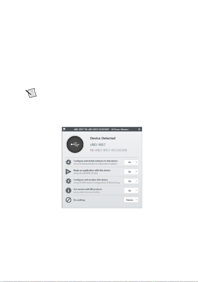
Note The device driver software automatically detects the cRIO-905x. If the
device driver software does not detect the cRIO-905x, verify that you installed
the appropriate NI software in the correct order on the host computer as
described in Installing Software on the Host Computer in the NI cRIO-905x
Getting Started Guide.
4. Select Configure and install software to this device.
NI cRIO-905x User Manual | © National Instruments | 3
Page 4
Connecting the cRIO-905x to the Host Computer or Network Using Ethernet
Complete the following steps to connect the cRIO-905x to a host computer or Ethernet
network using the RJ-45 Gigabit Ethernet port 0. NI recommends using the RJ-45 Gigabit
Ethernet port 0 for communication with deployed systems.
Note If your controller has the RJ-45 Gigabit Ethernet port 1, you can configure
that port in Measurement & Automation Explorer (MAX) under the Network
Settings tab.
1. Power on the host computer or Ethernet hub.
2. Connect the RJ-45 Gigabit Ethernet port 0 on the cRIO-905x to the host computer or
Ethernet hub using a standard Category 5 (CAT-5) or better shielded, twisted-pair
Ethernet cable.
Notice To prevent data loss and to maintain the integrity of your Ethernet
installation, do not use a cable longer than 100 m (328 ft).
The cRIO-905x attempts to initiate a DHCP network connection the first time you
connect using Ethernet. The cRIO-905x connects to the network with a link-local IP
address with the form 169.254.x.x if it is unable to initiate a DHCP connection.
Finding the cRIO-905x on the Network (DHCP)
Complete the following steps to find the cRIO-905x on a network using DHCP.
1. Disable secondary network interfaces on the host computer, such as a wireless access
card on a laptop.
2. Ensure that any anti-virus and firewall software running on the host computer allows
connections to the host computer.
Note MAX uses UDP on port 44525. Refer to the documentation of your
firewall software for information about configuring the firewall to allow
communication through this port.
3. Launch MAX on the host computer.
4. Expand Remote Systems in the configuration tree and locate your system.
Tip MAX lists the system under the model number followed by the serial
number, such as NI-cRIO-905x-1856AAA.
Tip If you do not see the cRIO-905x under Remote Systems, use the
Troubleshoot Remote System Discovery utility to walk through
troubleshooting steps.
Configuring Startup Options
Complete the following steps to configure the cRIO-905x startup options in MAX.
1. In MAX, expand your system under Remote Systems.
2. Select the Startup Settings tab to configure the startup settings.
4 | ni.com | NI cRIO-905x User Manual
Page 5
cRIO-905x Startup Options
You can configure the following cRIO-905x startup options.
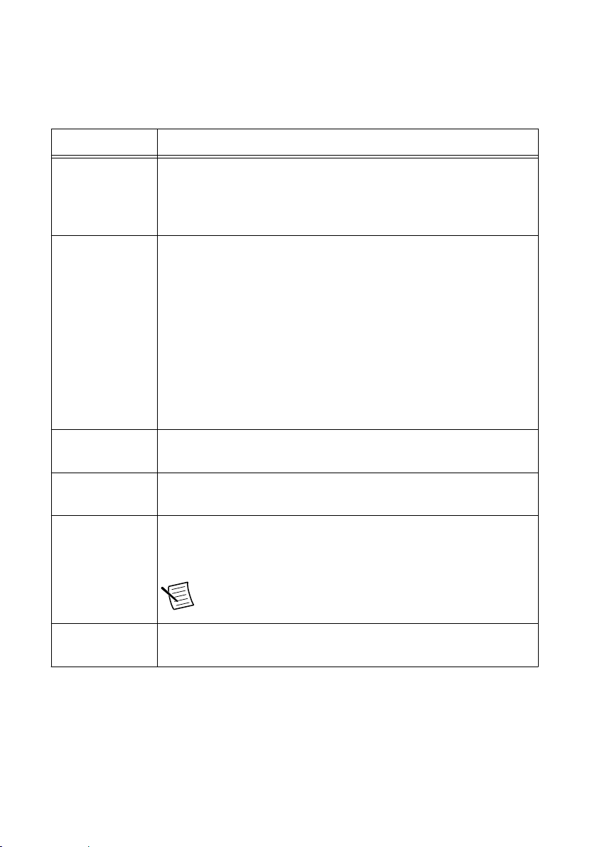
Table 1. cRIO-905x Startup Options
Startup Option Description
Force Safe Mode Rebooting the cRIO-905x with this setting on starts the cRIO-905x
without launching LabVIEW Real-Time or any startup applications. In
safe mode, the cRIO-905x launches only the services necessary for
updating configuration and installing software.
Enable Console
Out
Disable RT
Startup App
Disable FPGA
Startup App
Enable Secure
Shell (SSH)
Logins
LabVIEW Project
Access
Rebooting the cRIO-905x with this setting on redirects the console
output to the USB 2.0 Type-C Device Port with Console Out. You can
use a serial-port terminal program to read the IP address and firmware
version of the cRIO-905x. Make sure that the serial-port terminal
program is configured to the following settings:
• 115,200 bits per second
• Eight data bits
• No parity
• One stop bit
• No flow control
Rebooting the cRIO-905x with this setting on prevents any LabVIEW
startup applications from running.
Rebooting the cRIO-905x with this setting on prevents autoloading of
any FPGA application.
Rebooting the cRIO-905x with this setting on starts sshd on the
cRIO-905x. Starting sshd enables logins over SSH, an encrypted
communication protocol.
Note Visit ni.com/info and enter the Info Code openssh
for more information about SSH.
Rebooting the cRIO-905x with this setting on enables you to add the
target to a LabVIEW project.
NI cRIO-905x User Manual | © National Instruments | 5
Page 6
cRIO-905x Features
1
2
3
4
5
6
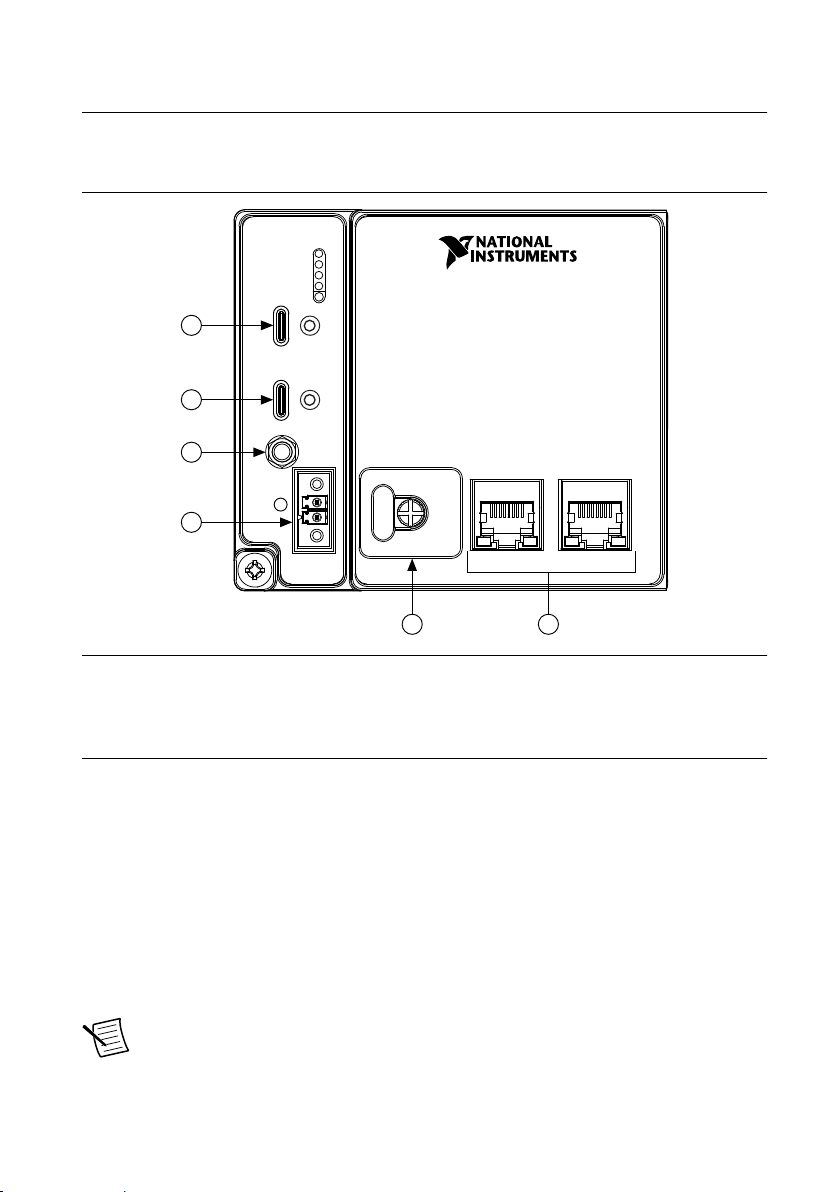
Ports and Connectors
Figure 1. cRIO-905x Ports and Connectors
1. USB 2.0 Type-C Device Port with Console Out
2. USB 3.1 Type-C Host Port
3. PFI 0
4. Power Connector
5. SD Association MicroSD Card Removable
Storage
6. RJ-45 Gigabit Ethernet Ports (one or two,
depending on the model)
USB 2.0 Type-C Device Port with Console Out
When operating a device, use this port to connect the cRIO-905x to a host PC. The USB
device functionality provides an alternate method to connect the controller to a host PC for
configuration, application deployment, debugging, and maintenance.
Console Out over USB requires a virtual COM port driver on the host PC. This driver installs
with CompactRIO 18.1 or later.
You must enable Console Out on the cRIO-905x in Measurement & Automation Explorer
(MAX) or by booting the controller into Safe Mode.
Note This port cannot be accessed by the user application when the Console Out
startup option is enabled.
6 | ni.com | NI cRIO-905x User Manual
Page 7
USB 3.1 Type-C Host Port
V
C
The USB host port on the cRIO-905x support common USB mass-storage devices such as
USB Flash drives, USB-to-IDE adapters, keyboards, mice, and USB cameras.
The following NI USB Type-C adapters are available for the cRIO-905x.
Table 2. NI USB Type-C Adapters for cRIO-905x
Cable Length Part Number
USB Cable with Retention, Type-C Male to Type-A Female, USB
0.5 m 143555-0R5
3.1, 3A
The following NI cables with retention are available for use with the cRIO-905x.
Table 3. NI USB Cables with Retention
Cable Length Part Number
0.3 m 143556-0R3
USB Cable with Retention, Type-C Male to Type-C Male, USB 3.1,
3A
1 m 143556-01
2 m 143556-02
PFI 0
The Programmable Function Interface (PFI) terminal is a SMB connector. You can configure
the PFI terminal as a timing input or timing output signal for AI, AO, DI, DO, or counter/timer
functions.
Note The PFI 0 terminal can only be used while the module is in the Real Time
programmatic mode. For more information about programming modes, refer to
Choosing Your Programming Mode.
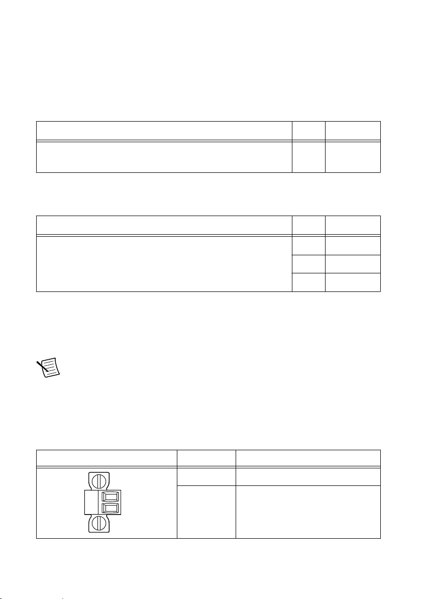
Power Connector
The cRIO-905x has a power connector to which you can connect a power supply.
Table 4. Power Connector Pinout
Pinout Pin Description
V Power input
C Common
NI cRIO-905x User Manual | © National Instruments | 7
Page 8
The cRIO-905x has reverse-voltage protection.
The following NI power supplies and accessories are available for use with the cRIO-905x.
Table 5. Power Supplies
Accessory Part Number
NI PS-10 Desktop Power Supply, 24 V DC, 5 A, 100-120/200-240 V AC
782698-01
Input
NI PS-14 Industrial Power Supply, 24 to 28 V DC, 3.3 A, 100-240 V AC
783167-01
Input
NI PS-15 Industrial Power Supply, 24 to 28 V DC, 5 A, 100/230 V AC Input 781093-01
NI PS-16 Industrial Power Supply, 24 to 28 V DC, 10 A, 115/230 V AC Input 781094-01
NI PS-17 Industrial Power Supply, 24 to 28 V DC, 20 A, 85-276 V AC Input 781095-01
Table 6. Power Accessories
Accessory Part Number
2-Position Screw Terminal Power Connector for cRIO-905x (Qty 4) 786902-01
NI 9971 Backshell for 2-Position Connector Block (Qty 4) 196375-01
MicroSD Card Removable Storage
The cRIO-905x has a microSD card slot that reads from and writes to microSD cards. The slot
supports microSD card interface speeds up to UHS-I DDR50.
Notice Using microSD cards that are not approved by NI might invalidate
specifications and result in unreliable performance.
The following accessories are available for use with the cRIO-905x.
Table 7. MicroSD Storage Accessories
Accessory Capacity Part Number
Industrial microSD card, -40 °C to 85 °C, UHS-I 16 GB 786913-01
MicroSD card slot cover (x3) — 786901-01
8 | ni.com | NI cRIO-905x User Manual
Page 9
MicroSD Card Slot Cover
1
2
3
4
5
6
7
8
You must use the microSD card slot cover to protect the microSD card in hazardous locations.
Do not remove a microSD card while the SD IN USE LED is flashing or solid because file
corruption may result.
Note Screw the slot cover closed completely. Tighten the captive screws to a
maximum torque of 0.75 N · m (6.7 lb · in.) using a #1 Phillips screwdriver. Do not
overtighten.
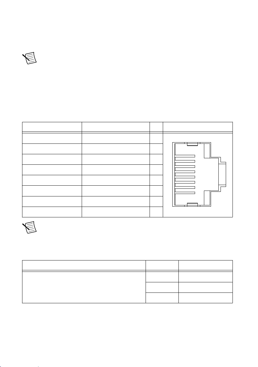
RJ-45 Gigabit Ethernet Port
The cRIO-905x will have one or two tri-speed RJ-45 Gigabit Ethernet ports. By default, the
Ethernet port is enabled and configured to obtain an IP address automatically. The Ethernet
port can be configured in MAX.
Table 8. RJ-45 Gigabit Ethernet Port Pinout
Fast Ethernet Signal Gigabit Ethernet Signal Pin Pinout
TX+ TX_A+ 1
TX- TX_A- 2
RX+ RX_B+ 3
No Connect TX_C+ 4
No Connect TX_C- 5
RX- RX_B- 6
No Connect RX_D+ 7
No Connect RX_D- 8
Note The Ethernet port performs automatic crossover configuration so you do not
need to use a crossover cable to connect to a host computer.
The following NI Ethernet cables are available for use with the cRIO-905x.
Table 9. RJ-45 Gigabit Ethernet Cables
Cables Length Part Number
2 m 151733-02
CAT-5E Ethernet Cable, shielded
5 m 151733-05
10 m 151733-10
NI cRIO-905x User Manual | © National Instruments | 9
Page 10
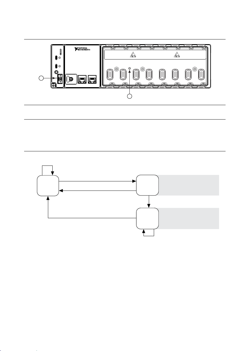
Buttons
1 2 3
4 5 6 7 8
1
2
Press and hold RESET button for ≥ 5 s
Press and hold RESET button for < 5 s
Run Mode
Safe Mode
Press and hold RESET button for < 5 s
Press and hold RESET button for ≥ 5 s
Press and hold
RESET button for ≥ 5 s
Press and hold
RESET button for < 5 s
• Console Out enabled
• Network settings reset
• RT Startup App disabled
• FPGA Startup App disabled
• Console Out enabled
• RT Startup App disabled
• FPGA Startup App disabled
Safe Mode
Figure 2. cRIO-905x Buttons
1. RESET Button
2. CMOS Reset Button
RESET Button
Press the RESET button to reset the processor in the same manner as cycling power.
Figure 3. Reset Button Behavior
For more information about using the RESET button for network troubleshooting, see
Troubleshooting Network Connectivity.
Troubleshooting Network Connectivity
You can use the RESET button to troubleshoot network connectivity.
Complete the following steps to reset the network adapters to default settings.
1. Hold the RESET button for 5 seconds, and then release it to boot the controller in safe
mode and enable Console Out.
2. Hold the RESET button again for 5 seconds to boot the controller into safe mode, enable
Console Out, and reset network adapters to default settings.
10 | ni.com | NI cRIO-905x User Manual
Page 11
CMOS Reset Button
1
2
3
4
5
6
The cRIO-905x has a CMOS reset button that you can use to reset the CMOS and the BIOS.
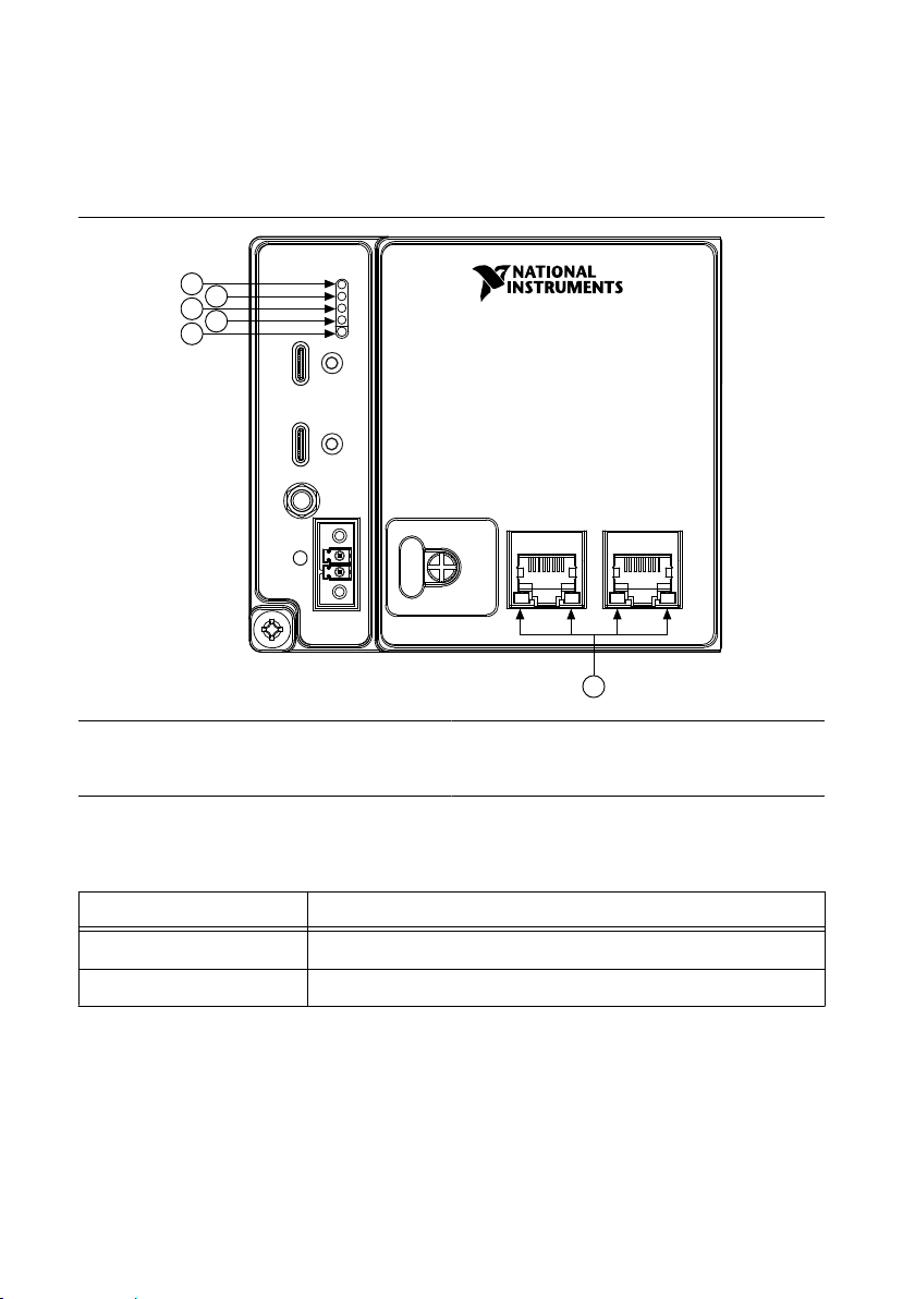
LEDs
Figure 4. cRIO-905x Front Panel LEDs
1. POWER LED
2. STATUS LED
3. SD IN USE LED
4. USER1 LED
5. USER FPGA1 LED
6. Gigabit Ethernet LEDs
POWER LED Indicators
LED Pattern Indication
Solid The cRIO-905x is powered on.
Off The cRIO-905x is powered off.
Table 10. POWER LED Indicators
NI cRIO-905x User Manual | © National Instruments | 11
Page 12

STATUS LED Indicators
Table 11. STATUS LED Indicators
LED Pattern Indication
Blinks twice and
pauses
Blinks three times
and pauses
Blinks four times
and pauses
Continuously blinks The cRIO-905x has not booted into NI Linux Real-Time. The
On momentarily The cRIO-905x is booting. No action required.
Off The cRIO-905x is in run mode. Software is installed and the operating
The cRIO-905x is in safe mode. Software is not installed, which is the
factory default state, or software has been improperly installed on the
cRIO-905x. An error can occur when an attempt to upgrade the
software is interrupted. Reinstall software on the cRIO-905x. Refer to
the Measurement & Automation Explorer (MAX) Help for information
about installing software on the cRIO-905x.
The cRIO-905x is in user-directed safe mode, or the cRIO-905x is in
install mode to indicate that software is currently being installed. This
pattern may also indicate that the user has forced the cRIO-905x to
boot into safe mode by pressing the reset button for longer than five
seconds or by enabling safe mode in MAX. Refer to the Measurement
& Automation Explorer (MAX) Help for information about safe mode.
The cRIO-905x is in safe mode. The software has crashed twice
without rebooting or cycling power between crashes.
cRIO-905x either booted into an unsupported operating system, was
interrupted during the boot process, or detected an unrecoverable
software error. If the problem persists, contact NI for support.
system is running.
User LEDs
You can define the behavior of the USER1 LED and the USER FPGA1 LED to meet the needs
of your application.
12 | ni.com | NI cRIO-905x User Manual
Page 13
Table 12. User LEDs
LED LED Color Description
USER1 Green Use LabVIEW Real-Time to define the USER1 LED with the
RT LEDs VI. For more information about the RT LEDs VI, refer
to the LabVIEW Help.
USER
FPGA1
Green Use the LabVIEW FPGA Module and NI-RIO Device Drivers
software to define the USER FPGA1 LED. Use the USER
FPGA1 LED to help debug your application or retrieve
application status. Refer to the LabVIEW Help for information
about programming this LED.
SD IN USE LED Indicators
Table 13. SD IN USE LED Indicators
LED Pattern Indication
Solid A microSD card is present and mounted.
Off No microSD card is present.
Ethernet LED Indicators
Table 14. Ethernet LED Indicators
LED LED Color LED Pattern Indication
ACT/LINK — Off LAN link not established
Green Solid LAN link established
Flashing Activity on LAN
10/100/1000 Yellow Solid 1,000 Mb/s data rate selected
Green Solid 100 Mb/s data rate selected
— Off 10 Mb/s data rate selected
NI cRIO-905x User Manual | © National Instruments | 13
Page 14
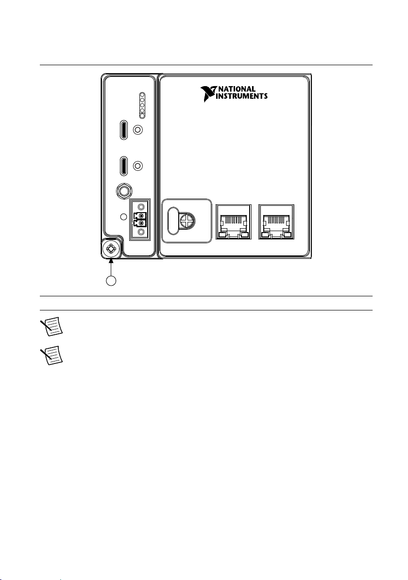
Chassis Grounding Screw
1
Figure 5. cRIO-905x Chassis Grounding Screw
1. Chassis Grounding Screw
Note For information about grounding the cRIO-905x, see Grounding the
Controller in the NI cRIO-905x Getting Started Guide.
Note For more information about ground connections, visit ni.com/info and enter
the Info Code emcground.
Internal Real-Time Clock
The cRIO-905x contains an internal real-time clock that maintains system time when the
cRIO-905x is powered off. The system clock of the cRIO-905x is synchronized with the
internal real-time clock at startup. You can set the real-time clock using the BIOS setup utility
or MAX, or you can set the real-time clock programmatically using LabVIEW.
Refer to the model specifications on ni.com/manuals for the real-time clock accuracy
specifications.
Digital Routing
The digital routing circuitry of the cRIO-905x manages the flow of data between the bus
interface and the acquisition and generation sub-systems when programming C Series modules
in Real-Time (NI-DAQmx) mode. The subsystems include analog input, analog output, digital
14 | ni.com | NI cRIO-905x User Manual
Page 15
I/O, and counters. The digital routing circuitry uses FIFOs (if present) in each sub-system to
Onboard
100 MHz
Oscillator
Clock
Generator
DAQ ASIC
RIO FPGA
cRIO Trigger Bus
80 MHz Timebase
20 MHz Timebase
100 kHz Timebase
13.1072 MHz Timebase
12.8 MHz Timebase
10 MHz Timebase
40 MHz Onboard Clock
÷200
13.1072 MHz Carrier Clock
12.8 MHz Carrier Clock
10 MHz Carrier Clock
÷2
÷4
ensure efficient data movement.
Note When programming C Series modules in FPGA mode, the flow of data
between the modules and the bus interface is programmed using LabVIEW FPGA.
The digital routing circuitry also routes timing and control signals. The acquisition and
generation sub-systems use these signals to manage and synchronize acquisitions and
generations. These signals can come from the following sources:
• C Series modules programmed in Real-Time (NI-DAQmx) mode
• User input through the PFI terminals using parallel digital C Series modules or the
cRIO-905x PFI 0 terminal
• FPGA or DAQ ASIC using the cRIO trigger bus to share hardware triggers and signals
between the LabVIEW FPGA and DAQmx applications
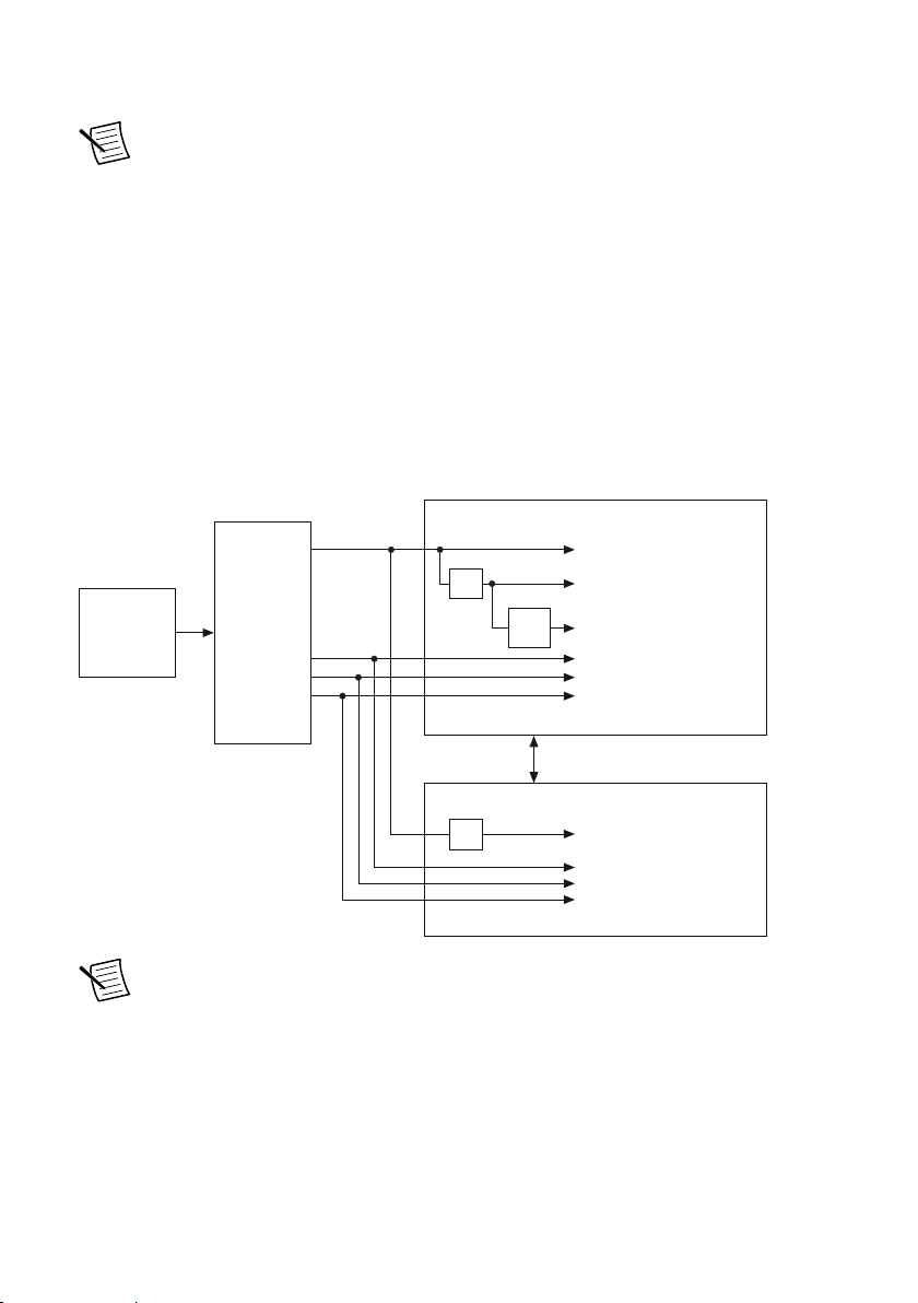
Clock Routing
The following figure shows the clock routing circuitry of the cRIO-905x.
Figure 6. Clock Routing Circuitry of the cRIO-905x
Note When switching between programming modes, you may notice the terms
timebase and clock used interchangeably. This is due to the DAQ ASIC and the RIO
FPGA using different terminology for timing and clock mechanisms. The
documentation will use the term based on the programming mode discussed.
80 MHz Timebase
When programming C Series modules in Real-Time (NI-DAQmx) mode, the 80 MHz
timebase can function as the source input to the 32-bit general-purpose counter/timers. The
80 MHz timebase is generated from the onboard oscillator.
NI cRIO-905x User Manual | © National Instruments | 15
Page 16

20 MHz and 100 kHz Timebases
When programming C Series modules in Real-Time (NI-DAQmx) mode, the 20 MHz and
100 kHz timebases can be used to generate many of the analog input and analog output timing
signals. These timebases can also function as the source input to the 32-bit general-purpose
counter/timers. The 20 MHz and 100 kHz timebases are generated by dividing down the
80 MHz timebase, as shown in the previous figure.
40 MHz Onboard Clock
When programming C Series modules in FPGA mode, the 40 MHz onboard clock is used as
the top-level clock for your LabVIEW FPGA application and C Series module IO nodes. The
40 MHz onboard clock can be used to clock single-cycle timed loops. Derived clocks of
varying frequency can be generated from the 40 MHz onboard clock. The 40 MHz onboard
clock is phase aligned with the incoming 80 MHz clock.
13.1072 MHz, 12.8 MHz, and 10 MHz Timebases and Carrier Clocks
When programming C Series modules in Real-Time (NI-DAQmx) mode, the 13.1072 MHz,
12.8 MHz, and 10 MHz timebases can be used to generate many of the analog input and
analog output timing signals. These timebases can also function as the source input to the 32bit general-purpose counter/timers. The 13.1072 MHz, 12.8 MHz, and 10 MHz timebases are
generated directly from the onboard clock generator.
When programming C Series modules in FPGA mode, the 13.1072 MHz, 12.8 MHz, and
10 MHz carrier clocks can be used as the master clock for C Series analog input and analog
output modules. The 13.1072 MHz, 12.8 MHz, and 10 MHz carrier clocks are available as IO
Nodes in LabVIEW FPGA applications and can be used to correlate the onboard clocks with
self-timed C Series modules containing free-running clocks.
Synchronization Across a Network
Internal Timebase
The onboard 100 MHz oscillator automatically synchronizes to other network-synchronized
devices that are part of the local IEEE 802.1AS or IEEE 1588-2008 subnet, depending on the
active time reference that is being used on the controller.
The 80 MHz, 40 MHz, 20 MHz, 100 kHz, 13.1072 MHz, 12.8 MHz, and 10 MHz timebases
are derived from the onboard oscillator and are synchronized to it. Therefore, the timebases are
also synchronized to other network-synchronized timebases on the IEEE 802.1AS or
IEEE 1588-2008 subnet. This enables analog input, analog output, digital I/O, and counter/
timers to be synchronized to other chassis across a distributed network.
When programming C Series modules in FPGA mode, the Time Synchronization IO Nodes
can be used to synchronize the LabVIEW FPGA application to other network-synchronized
devices.
16 | ni.com | NI cRIO-905x User Manual
Page 17

Network-based Synchronization
IEEE 1588, also known as the precision time protocol (PTP), is an Ethernet-based
synchronization method designed for cabled, local networks. The PTP protocol provides a
fault tolerant method of synchronizing all participating clocks to the highest quality clock in
the network. This method of synchronization between networked devices uses packet-based
communication and is possible over the long distances allowed for each Ethernet link, without
signal propagation impact. IEEE 1588 has many different profiles, such as
IEEE 802.1AS-2011, each of which use different features. Because the profiles are not
interoperable with each other, make sure it is known which profile is implemented on the
device. For devices on the network to synchronize with each other using IEEE 1588, all
devices must be compatible with the desired IEEE 1588 profile and must all be connected
within the selected IEEE 1588 profile-compliant network infrastructure.
The cRIO-905x controllers are compatible with both the IEEE 802.1AS-2011 profile and the
IEEE 1588-2008 (1588v2) Delay Request-Response profile. However, each network port must
be configured individually to the specific profile required for the network.
Differences Between IEEE 802.1AS-2011 and IEEE 1588-2008
IEEE 802.1AS-2011, also known as the generalized precision time protocol (gPTP), is a
profile of IEEE 1588. A cRIO-905x controller can be configured to use either the
IEEE 802.1AS-2011 profile or the IEEE 1588-2008 profile by configuring the port’s time
reference. If a user does not explicitly specify which time reference to use a cRIO-905x
controller will default to use the IEEE 802.1AS-2011 profile. There are some differences
between the IEEE 802.1AS-2011 profile and the IEEE 1588-2008 profile which are called out
below:
• IEEE 802.1AS-2011 assumes all communication between devices is done on the OSI
layer 2, while IEEE 1588-2008 can support various layer 2 and layer 3-4 communication
methods. The IEEE 1588-2008 profile National Instruments implements on the
cRIO-905x only supports layer 3-4 communication methods. Operating on the layer 2
yields better performance for the IEEE 802.1AS-2011.
• IEEE 802.1AS-2011 only communicates gPTP information directly with other
IEEE 802.1AS devices within a system. Therefore, there must be IEEE 802.1AS-2011
support along the entire path from one IEEE 802.1AS-2011 device to another. With
IEEE 1588-2008, it is possible to use non-IEEE 1588-2008 switches between two
IEEE 1588-2008 devices. The benefit of having IEEE 802.1AS-2011 support along the
entire path is a faster performance and lower jitter compared to IEEE 1588-2008.
• With IEEE 802.1AS-2011 there are only two types of time-aware systems: time-aware
end stations and time-aware bridges. Whereas with IEEE 1588-2008, there are the
following: ordinary clock, boundary clock, end-to-end transparent clock and a time-aware
bridges. Based on these factors, IEEE 802.1AS-2011 can reduce complexity and
configuration challenges compared to IEEE 1588-2008. A cRIO-905x controller acts as a
time-aware end station for both protocols.
NI cRIO-905x User Manual | © National Instruments | 17
Page 18

IEEE 1588 External Switch Requirements
To take advantage of the network synchronization features of the cRIO-905x controllers,
ensure that your network infrastructure meets certain requirements depending on which
IEEE 1588 profile is implemented for your application:
• IEEE 802.1AS-2011 support—Automatically enables timebase synchronization and
enables the use of time-based triggers and timestamping between devices across the
network. Synchronization performance will meet NI product specifications.
• IEEE 1588-2008 support—Enables timebase synchronization and enables the use of timebased triggers and timestamping between devices across the network. Synchronization
performance will vary and may not meet NI product specifications. As a default
configuration for IEEE 1588-2008, NI supports the IEEE 1588 Delay Request-Response
profile, using the UDP over IP transport (layer 3-4).
Battery
The cRIO-905x contains a lithium cell battery that stores the system clock information when
the cRIO-905x is powered off. There is only a slight drain on the battery when power is
applied to the cRIO-905x power connector. The rate at which the battery drains when power is
disconnected depends on the ambient storage temperature. For longer battery life, store the
cRIO-905x at a cooler temperature and apply power to the power connector. Refer to the
specifications on ni.com/manuals for the expected battery lifetime.
The battery is not user-replaceable. If you need to replace the battery, contact NI. Refer to the
controller specifications on ni.com/manuals for information about battery disposal.
File System
LabVIEW mounts USB devices and microSD cards to the media/sdx1 directory and creates
symbolic links /u, /v, /w, or /x to the media mount point, starting with /u if it is available.
To prevent any file corruption to external storage devices, verify that any file IO operations
with the specific drive finish before removing the device. Refer to the LabVIEW Help for more
information.
The file system of the cRIO-905x follows conventions established for UNIX-style operating
systems. Other LabVIEW Real-Time targets follow Microsoft Windows-style conventions. In
order to facilitate the porting of applications from those targets, this target supports the
Windows-style /C home directory. This path is bound to the UNIX-style directory /home/
lvuser.
Various LabVIEW Real-Time system files which would be accessible from C: (or /C) on
other LabVIEW Real-Time targets are found in different locations on this target.
UNIX-style file systems support the concept of a symbolic link, which allows access to a file
using an alternative file path. For example, it is possible to link /C/ni-rt/system, where
dynamic libraries are deployed on other LabVIEW Real-Time targets, to /usr/local/lib,
where they are stored on the cRIO-905x, if the application requires this.
For more information, visit ni.com/info and enter the Info Code RT_Paths.
18 | ni.com | NI cRIO-905x User Manual
Page 19
Mounting the Controller
3
4
1
2
To obtain the maximum ambient temperature, you must mount the cRIO-905x in the reference
mounting configuration shown in the following image. Mounting the cRIO-905x in the
reference mounting configuration ensures that your system will operate correctly across the
full operating temperature range and provide optimal C Series module accuracy. Observe the
following guidelines to mount the cRIO-905x in the reference mounting configuration.
Figure 7. System Mounting Configuration
NI cRIO-905x User Manual | © National Instruments | 19
Page 20
1
Vertical mounting orientation.
2
3
4
1 2 3
4 5 6 7 8
25.4 mm
(1.00 in.)
Mounting substrate options:
• Mount the cRIO-905x directly to a metallic surface that is at least 1.6 mm
(0.062 in.) thick and extends a minimum of 101.6 mm (4 in.) beyond all edges of
the device.
• Use the NI Panel Mounting Kit to mount the cRIO-905x to a metallic surface that is
at least 1.6 mm (0.062 in.) thick and extends a minimum of 101.6 mm (4 in.)
beyond all edges of the device.
Observe the minimum spacing dimensions in the Mounting Requirements section.
Allow space for cabling clearance according to the Mounting Requirements section.
Tip Before mounting the controller, record the serial number from the side of the
cRIO-905x so that you can identify the cRIO-905x in MAX. You will be unable to
read the serial number after you mount the controller.
Alternative Mounting Configurations
The maximum operating temperature may be reduced for any mounting configuration other
than the reference mounting configuration. A 10 °C (18 °F) reduction in maximum operating
temperature is sufficient for most alternate mounting configurations. Follow the guidelines
above for all mounting configurations. The published accuracy specifications, although not
guaranteed for alternate mounting configurations, may be met depending on the system power
and the thermal performance of the alternate mounting configuration. Contact NI for further
details regarding the impact of common alternate mounting configurations on maximum
operating temperature and module accuracy.
Contact NI for further details regarding the system impact of common alternative mounting
configurations.
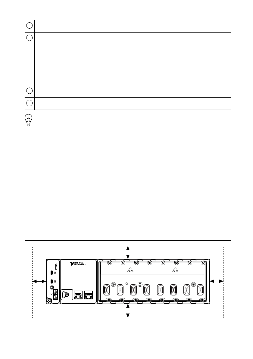
Mounting Requirements
Figure 8. Minimum Spacing Dimensions
20 | ni.com | NI cRIO-905x User Manual
Page 21
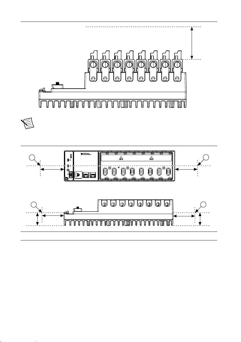
Figure 9. Cabling Clearance
1 2 3
4 5 6 7 8
38.1 mm
(1.50 in.)
63.5 mm
(2.50 in.)
63.5 mm
(2.50 in.)
38.1 mm
(1.50 in.)
63.5 mm
(2.50 in.)
63.5 mm
(2.50 in.)
1
1
1
1
Note The various connector types on C Series modules require different cabling
clearances. For a complete list of cabling clearances for C Series modules, visit
ni.com/info and enter the Info Code crioconn.
Figure 10. Ambient Temperature Measurement Location
1. Measure the ambient temperature here.
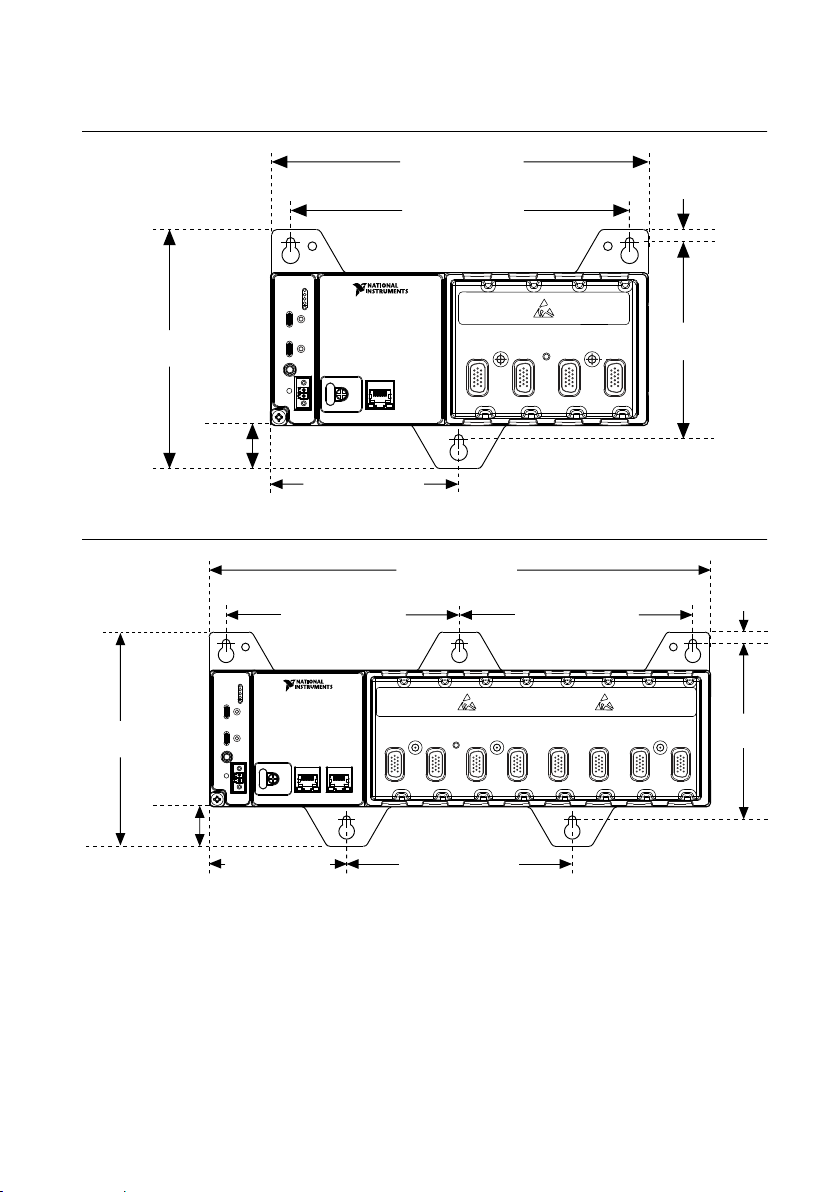
Dimensions
The following dimensional drawings apply to all cRIO-905x controllers. For detailed
dimensional drawings and 3D models, visit ni.com/dimensions and search for the model
number.
NI cRIO-905x User Manual | © National Instruments | 21
Page 22
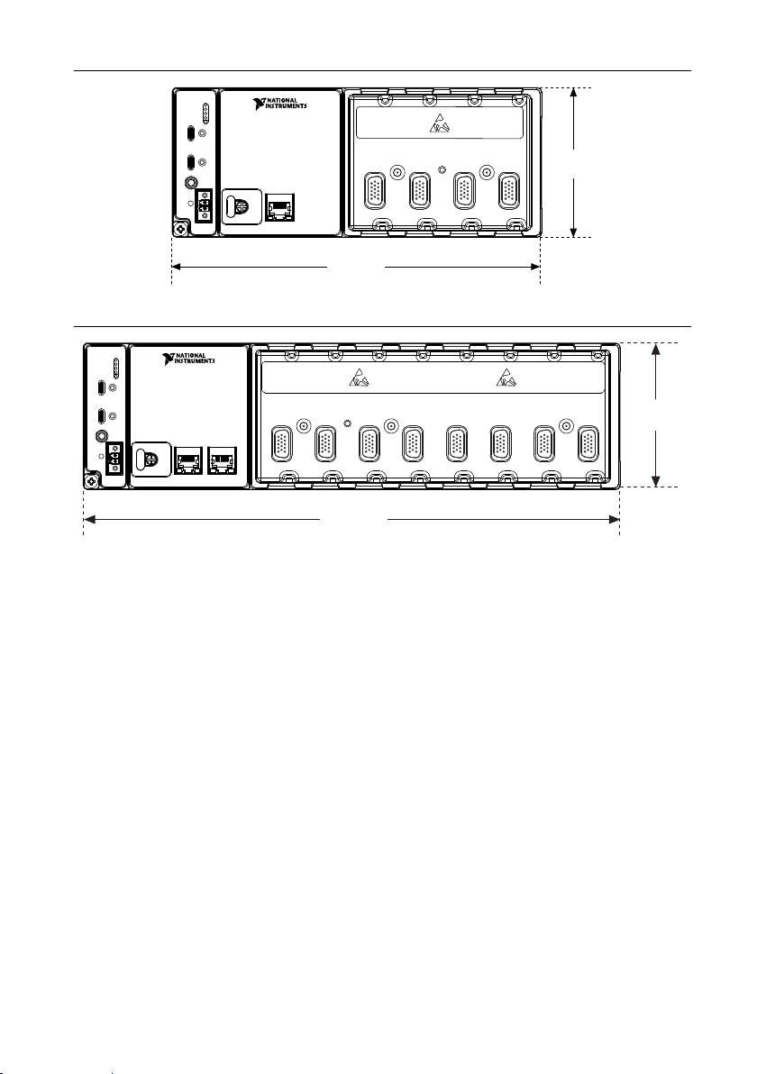
Figure 11. cRIO-905x 4-slot Controller Front Dimensions
1 2 3
4
221.40 mm
(8.72 in.)
89.61 mm
(3.528 in.)
1 2 3
4 5 6 7 8
328.64 mm
(12.938 in.)
89.61 mm
(3.528 in.)
Figure 12. cRIO-905x 8-slot Controller Front Dimensions
22 | ni.com | NI cRIO-905x User Manual
Page 23
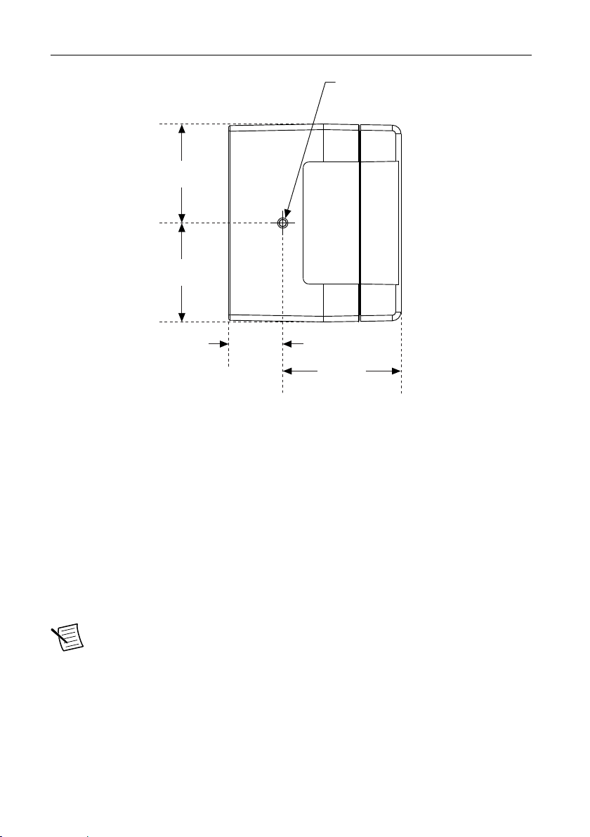
Figure 13. cRIO-905x Side Dimensions
44.81 mm
(1.764 in.)
44.81 mm
(1.764 in.)
53.52 mm
(2.107 in.)
24.35 mm
(0.959 in.)
M4 x 0.7 Thread
5.00 mm (0.20 in.)
Max Insertion Depth
Front Mounting on a Flat Surface
What to Use
• cRIO-905x
• M4 screws, user-provided, length dependent on application
– x2 for 4-slot models
– x3 for 8-slot models
What to Do
Complete the following steps to front mount the cRIO-905x directly on a flat, rigid surface
using the mounting holes.
Note NI recommends surface mounting your system in environments with high
shock and vibration.
NI cRIO-905x User Manual | © National Instruments | 23
Page 24
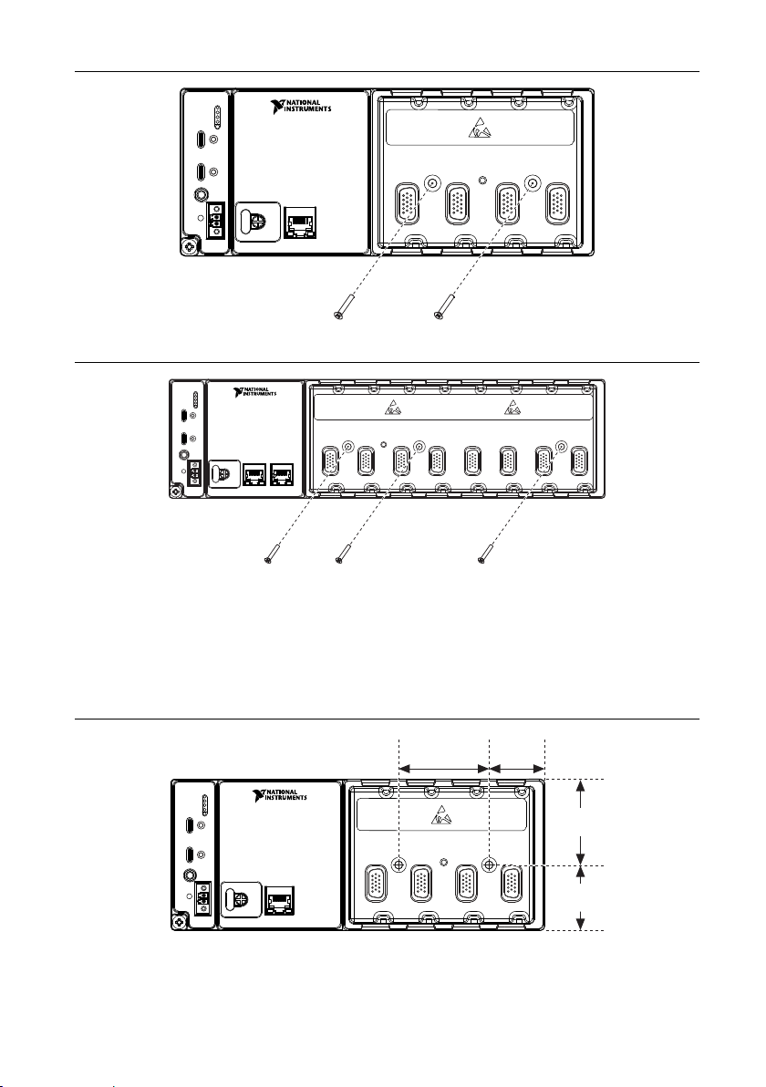
Figure 14. Front Mounting the 4-slot cRIO-905x Directly on a Flat Surface
1 2 3
4
1 2 3
4 5 6 7 8
1 2 3
4
41.1 mm
(1.62 in.)
47.0 mm
(1.85 in.)
47.2 mm
(1.86 in.)
30.6 mm
(1.20 in.)
Figure 15. Front Mounting the 8-slot cRIO-905x Directly on a Flat Surface
1. Prepare the surface for mounting the cRIO-905x using the Surface Mounting Dimensions.
2. Align the cRIO-905x on the surface.
3. Fasten the cRIO-905x to the surface using the M4 screws appropriate for the surface.
Surface Mounting Front Dimensions
Figure 16. 4-slot cRIO-905x Front Dimensions
24 | ni.com | NI cRIO-905x User Manual
Page 25
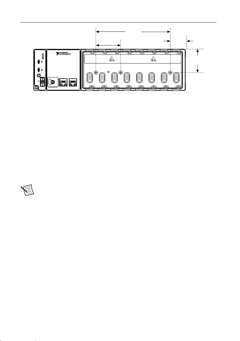
Figure 17. 8-slot cRIO-905x Front Dimensions
1 2 3
4 5 6 7 8
47.2 mm
(1.86 in.)
141.7 mm
(5.58 in.)
30.8 mm
(1.21 in.)
47.0 mm
(1.85 in.)
Rear Mounting on a Flat Surface
What to Use
• cRIO-905x
• M4 screws, user provided, which must not exceed 8 mm of insertion into the cRIO-905x
– x4 for 4-slot models
– x6 for 8-slot models
What to Do
Complete the following steps to rear mount the cRIO-905x directly on a flat, rigid surface
using the mounting holes.
Note NI recommends surface mounting your system in environments with high
shock and vibration.
NI cRIO-905x User Manual | © National Instruments | 25
Page 26
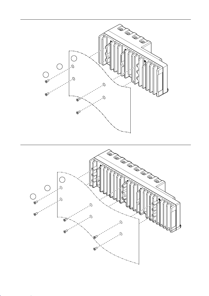
Figure 18. Rear Mounting the 4-slot cRIO-905x Directly on a Flat Surface
1
2
3
1
2
3
Figure 19. Rear Mounting the 8-slot cRIO-905x Directly on a Flat Surface
26 | ni.com | NI cRIO-905x User Manual
Page 27
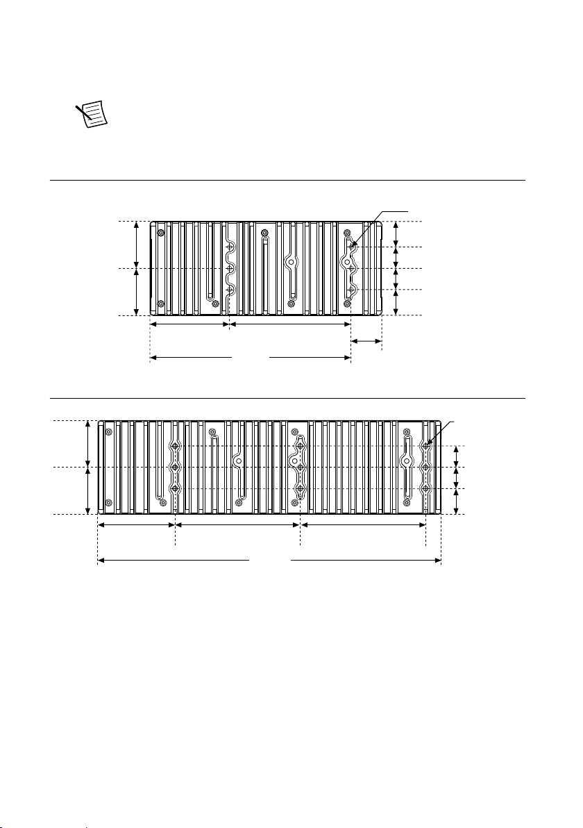
1. Prepare the surface for mounting the cRIO-905x using the Surface Mounting Dimensions.
6x M4 x 0.7
8.0 mm (0.315 in.)
Max Insertion Depth
38.79 mm
(1.527 in.)
24.48 mm
(0.964 in.)
24.49 mm
(0.964 in.)
20.33 mm
(0.800 in.)
20.32 mm
(0.800 in.)
50.82 mm
(2.001 in.)
75.89 mm
(2.988 in.)
116.54 mm
(4.588 in.)
221.4 mm
(8.72 in.)
29 mm
(1.142 in.)
328.6 mm
(12.94 in.)
120 mm
(4.72 in.)
24.5 mm
(0.96 in.)
20.3 mm
(0.80 in.)
20.3 mm
(0.80 in.)
9x M4 x 0.7
8.0 mm (0.32 in.)
Max Insertion Depth
38.8 mm
(1.52 in.)
50.8 mm
(2.00 in.)
73.8 mm
(2.91 in.)
120 mm
(4.72 in.)
2. Align the cRIO-905x on the surface.
3. Fasten the cRIO-905x to the surface using the M4 screws appropriate for the surface.
Note Screws must not exceed 8 mm of insertion into the cRIO-905x. Tighten
the screws to a torque of 1.3 N · m (11.5 lb · in.).
Surface Mounting Rear Dimensions
Figure 20. 4-slot cRIO-905x Rear Dimensions
Figure 21. 8-slot cRIO-905x Rear Dimensions
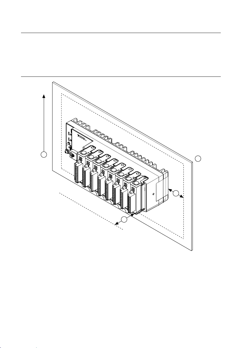
Mounting the Controller on a Panel
What to Use
• cRIO-905x
• Screwdriver, Phillips #2
NI cRIO-905x User Manual | © National Instruments | 27
Page 28
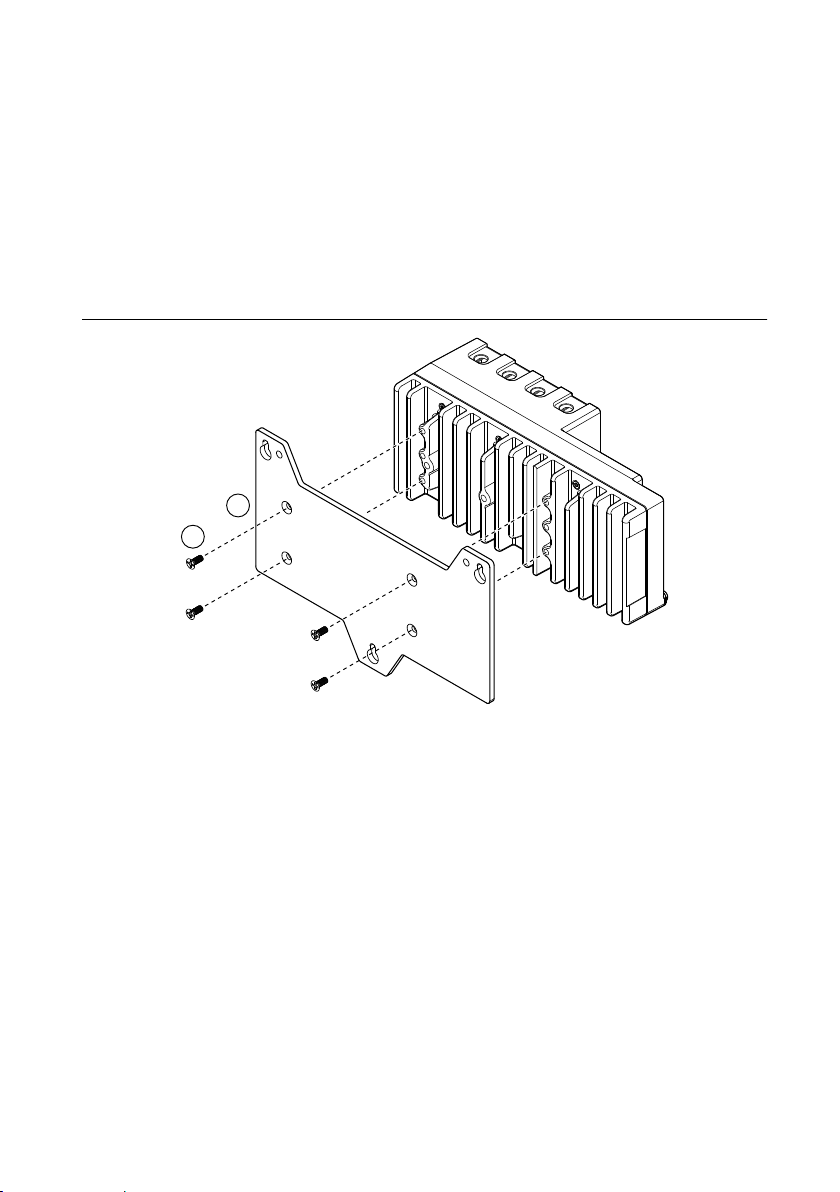
• NI panel mounting kit for 4-slot controllers, 157253-01
1
2
– Panel mounting plate
– M4 x 10 screws (x4)
• NI panel mounting kit for 8-slot controllers, 157267-01
– Panel mounting plate
– M4 x 10 screws (x6)
What to Do
Complete the following steps to mount the cRIO-905x on a panel.
Figure 22. Mounting the 4-slot cRIO-905x on a Panel
28 | ni.com | NI cRIO-905x User Manual
Page 29
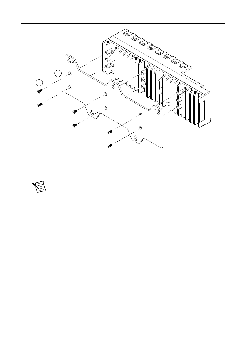
Figure 23. Mounting the 8-slot cRIO-905x on a Panel
1
2
1. Align the cRIO-905x and the panel mounting plate.
2. Fasten the panel mounting plate to the cRIO-905x using the screwdriver and M4 x 10
screws.
Note You must use the screws provided with the NI panel mounting kit
because they are the correct depth and thread for the panel mounting plate.
Tighten the screws to a torque of 1.3 N · m (11.5 lb · in.).
3. Fasten the panel mounting plate to the surface using the screwdriver and screws that are
appropriate for the surface. The maximum screw size is M5 or number 10.
NI cRIO-905x User Manual | © National Instruments | 29
Page 30
Panel Mounting Dimensions
108.8 mm (4.26 in.)
217.7 mm (8.57 in.)
199.4 mm (7.85 in.)
138.9 mm
(5.47 in.)
114.3 mm
(4.50 in.)
7.2 mm
(0.29 in.)
25.4 mm
(1.00 in.)
1 2 3
4
89.9 mm (3.54 in.)
147.3 mm (5.80 in.)
327 mm (12.88 in.)
152.4 mm (6.00 in.) 152.4 mm (6.00 in.)
138.9 mm
(5.47 in.)
114.3 mm
(4.50 in.)
7.2 mm
(0.29 in.)
25.4 mm
(1.00 in.)
1 2 3
4 5 6 7 8
Figure 24. 4-slot cRIO-905x Panel Mounting Dimensions
Figure 25. 8-slot cRIO-905x Panel Mounting Dimensions
30 | ni.com | NI cRIO-905x User Manual
Page 31

Mounting on a DIN Rail
1
2
What to Use
• cRIO-905x
• Screwdriver, Phillips #2
• NI DIN rail mounting kit
– 4-slot models - 157254-01
• DIN rail clip
• M4 x 10 screws (x2)
– 8-slot models - 157268-01
• DIN rail clip
• M4 x 10 screws (x3)
What to Do
Complete the following steps to mount the cRIO-905x on a standard 35-mm DIN rail.
Figure 26. Mounting the 4-slot cRIO-905x on a DIN Rail
NI cRIO-905x User Manual | © National Instruments | 31
Page 32

Figure 27. Mounting the 8-slot cRIO-905x on a DIN Rail
1
2
1
2
1. Align the DIN rail clip with the mounting holes on the rear of the cRIO-905x.
2. Fasten the DIN rail clip to the cRIO-905x using the screwdriver and M4 x 10 screws.
Note You must use the screws provided with the NI DIN rail kit because they
are the correct depth and thread for the DIN rail clip. Tighten the screws to a
torque of 1.3 N · m (11.5 lb · in.).
Clipping the Controller on a DIN Rail
Figure 28. Clipping the Controller on a DIN Rail
1. Latch the spring side (top) of the DIN clip onto the top edge of the DIN rail.
2. Press down firmly to compress the spring until the clip locks in place on the DIN rail.
Note Ensure that no C Series modules are in the controller before removing it from
the DIN rail.
32 | ni.com | NI cRIO-905x User Manual
Page 33

Mounting on a Rack
2 3
1
You can use the following rack mount kits to mount the controller and other DIN railmountable equipment on a standard 482.6 mm (19 in.) rack.
• Industrial Rack Mount Kit, 786411-01
• NI Rack-Mounting Kit, 781989-01
Note You must use the appropriate NI DIN rail mounting kit for your model in
addition to a rack-mounting kit.
Mounting the Device on a Desktop
What to Use
• cRIO-905x
• Screwdriver, Phillips #1
• Screwdriver, Phillips #2
• Screwdriver, Torx T10
• NI desktop mounting kit, 779473-01
Figure 29. Components of the NI Desktop Mount Kit
1. Desktop mounting brackets (x2)
2. Adapter bracket
3. M3 x 35 screws (x2)
What to Do
Complete the following steps to mount the cRIO-905x on a desktop.
NI cRIO-905x User Manual | © National Instruments | 33
Page 34

Figure 30. Mounting the 4-Slot cRIO-905x on a Desktop
1
4
4
3
3
2
34 | ni.com | NI cRIO-905x User Manual
Page 35

Figure 31. Mounting the 8-Slot cRIO-905x on a Desktop
1
3
4
4
3
2
1. Use the Torx T10 screwdriver to remove the two screws from the back of the chassis on
the controller side.
2. Use the #1 Phillips screwdriver and the two M3 x 35 screws to attach the adapter bracket
to the chassis.
3. Align the desktop mounting brackets with the mounting holes at the end of the chassis
and on the adapter bracket.
4. Use a #2 Phillips screwdriver to tighten the captive screw on the end bracket.
NI cRIO-905x User Manual | © National Instruments | 35
Page 36

Desktop Mounting Dimensions
1 2 3
4
17.2 mm
(0.68 in.)
39.1 mm
(1.54 in.)
22.9 mm
(1.14 in.)
1 2 3
4 5 6 7 8
17.2 mm
(0.68 in.)
39.1 mm
(1.54 in.)
22.9 mm
(1.14 in.)
127.0 mm
(5.00 in.)
130.0 mm
(5.12 in.)
Figure 32. 4 Slot cRIO-905x Desktop Mounting Front Dimensions
Figure 33. 8 Slot cRIO-905x Desktop Mounting Front Dimensions
Figure 34. cRIO-905x Desktop Mounting Side Dimensions
36 | ni.com | NI cRIO-905x User Manual
Page 37

Choosing Your Programming Mode
The cRIO-905x supports three programming modes on a per slot basis.
RealTime
RealTime
Scan
Enables you to use C Series modules directly from LabVIEW Real-Time,
using NI DAQmx.
C Series modules appear under the Real-Time Resources item in the MAX
Project Explorer window and I/O channels appear as I/O variables under
the modules. To use I/O variables, you drag and drop them from the
Project Explorer window to LabVIEW Real-Time VIs.
Use this mode to make the C Series module behave like it is in a
CompactDAQ controller, using the Real-Time NI-DAQmx and NI-XNET
drivers to communicate, and access the four counter/timers and the PFI
trigger connector on the controller.
Enables you to use C Series modules directly from LabVIEW Real-Time,
using I/O variables.
C Series modules that you use in Scan Interface mode appear under the
Real-Time Scan Resources item in the MAX Project Explorer window
and I/O channels appear as I/O variables under the modules. To use I/O
variables, you drag and drop them from the Project Explorer window to
LabVIEW Real-Time VIs.
In this mode, you do not need to do any LabVIEW FPGA development.
LabVIEW programs the FPGA for you with a fixed FPGA bitfile that
communicates with all the C Series modules that RT Scan mode supports.
LabVIEW also sends C Series data to the Real-Time host to be displayed
in I/O variables. Real-Time Scan mode also enables you to dynamically
detect which types of C Series modules are plugged into chassis slots.
FPGA Enables you to use C Series modules from LabVIEW FPGA VIs.
C Series modules appear directly under the FPGA Target item in the
MAX Project Explorer window and I/O channels appear as FPGA I/O
items under the FPGA Target. To access the I/O channels, you either
configure FPGA I/O Nodes in a LabVIEW FPGA VI or drag and drop the
I/O channels from the Project Explorer window to a LabVIEW FPGA VI
block diagram.
Use this mode to add more flexibility, customization, timing, and
synchronization to your applications. To use the CompactRIO system in
FPGA mode, you must either have the LabVIEW FPGA Module installed
on the host computer, or have access to a compiled bitfile that you can
download to the FPGA. In either case, you use the Open FPGA VI
Reference function in a LabVIEW Real-Time VI to access the FPGA VI
or bitfile.
NI cRIO-905x User Manual | © National Instruments | 37
Page 38

Table 15. Supported Programming Modes for Popular Tasks
Task Real-Time Real-Time Scan FPGA
Control rates up to 1 kHz ■ ■
Control rates between 1 kHz and 2.5 kHz
(application dependent)
Control rates over 2.5 kHz ■
High-speed waveform acquisition ■ ■
Note Some C Series modules can only be used in certain programming modes. For
module-specific software support information, visit ni.com/info and enter the Info
Code swsupport.
To learn more about using the cRIO-905x in Real-Time mode, refer to the following sections:
• Analog Input with NI-DAQmx
• Analog Output with NI-DAQmx
• Digital Input/Output with NI-DAQmx
• PFI with NI-DAQmx
• Counters with NI-DAQmx
■ ■ ■
Analog Input with NI-DAQmx
To perform analog input measurements, install a supported analog input C Series module into
any slot on the cRIO controller and set the programming mode to Real-Time (NI-DAQmx)
mode. The measurement specifications, such as number of channels, channel configuration,
sample rate, and gain, are determined by the type of C Series module used. For more
information and wiring diagrams, refer to the documentation included with your C Series
modules.
The cRIO controller has eight input timing engines, which means that up to eight hardwaretimed analog input tasks can be running at a time on the controller. An analog input task can
include channels from multiple analog input modules. However, channels from a single
module cannot be used in multiple tasks.
Multiple timing engines allow the cRIO controller to run up to eight analog input tasks
simultaneously, each using independent timing and triggering configurations. The eight timing
engines are it0, it1,…it7.
Hardware-Timed Single Point (HWTSP) Mode
In HWTSP mode, samples are acquired or generated continuously using hardware timing and
no buffer. You must use the sample clock or change detection timing types. No other timing
types are supported.
Use HWTSP mode if you need to know if a loop executes in a given amount of time, such as
in a control application. Because there is no buffer, if you use HWTSP mode, ensure that reads
38 | ni.com | NI cRIO-905x User Manual
Page 39

or writes execute fast enough to keep up with hardware timing. If a read or write executes late,
it returns a warning.
Note DSA modules do not support HWTSP mode.
Analog Input Triggering Signal
A trigger is a signal that causes an action, such as starting or stopping the acquisition of data.
When you configure a trigger, you must decide how you want to produce the trigger and the
action you want the trigger to cause. The cRIO controller supports internal software triggering,
external digital triggering, analog triggering, and internal time triggering.
Three triggers are available: Start Trigger, Reference Trigger, and Pause Trigger. An analog or
digital signal can initiate these three trigger actions. C Series Parallel digital input modules and
the controller’s integrated PFI trigger line can be used in any controller slot to supply a digital
trigger. To find your module triggering options, refer to the documentation included with your
C Series modules. For more information about using digital modules for triggering, refer to the
Digital Input/Output with NI-DAQmx section.
Refer to the AI Start Trigger Signal, AI Reference Trigger Signal, and AI Pause Trigger Signal
sections for more information about the analog input trigger signals.
Analog Input Timing Signals
The cRIO controller features the following analog input timing signals:
• AI Sample Clock Signal*
• AI Sample Clock Timebase Signal
• AI Start Trigger Signal*
• AI Reference Trigger Signal*
• AI Pause Trigger Signal*
Signals with an * support digital filtering. Refer to the PFI Filters section for more
information.
Refer to the AI Convert Clock Signal Behavior For Analog Input Modules section for more
information about AI Convert Clock signals and the cRIO controller.
AI Sample Clock Signal
A sample consists of one reading from each channel in the AI task. Sample Clock signals the
start of a sample of all analog input channels in the task. The sample clock can be generated
from external or internal sources as shown in the figure below.
NI cRIO-905x User Manual | © National Instruments | 39
Page 40

Figure 35. AI Sample Clock Timing Options
Programmable
Clock
Divider
Sample Clock
Timebase
PFI
Analog Comparison Event
Ctr n Internal Output
AI Sample
Clock
Sigma-Delta Module Internal Output
Analog Comparison
Event
80 MHz Timebase
20 MHz Timebase
PFI
13.1072 MHz Timebase
12.8 MHz Timebase
10 MHz Timebase
100 kHz Timebase
Routing the Sample Clock to an Output Terminal
You can route Sample Clock to any output PFI terminal. Sample Clock is an active high pulse
by default.
AI Sample Clock Timebase Signal
The AI Sample Clock Timebase signal is divided down to provide a source for Sample Clock.
AI Sample Clock Timebase can be generated from external or internal sources. AI Sample
Clock Timebase is not available as an output from the controller.
AI Start Trigger Signal
Use the Start Trigger signal to begin a measurement acquisition which consists of one or more
samples. Once the acquisition begins, configure the acquisition to stop in one of the following
ways:
• When a certain number of points has been sampled (in finite mode)
• After a hardware reference trigger (in finite mode)
• With a software command (in continuous mode)
An acquisition that uses a start trigger (but not a reference trigger) is sometimes referred to as
a posttriggered acquisition. That is, samples are measured only after the trigger.
When you are using an internal sample clock, you can specify a default delay from the start
trigger to the first sample.
Using a Digital Source
To use the Start Trigger signal with a digital source, specify a source and a rising or falling
edge. Use the following signals as the source:
• Any PFI terminal
• Counter n Internal Output
40 | ni.com | NI cRIO-905x User Manual
Page 41

The source also can be one of several other internal signals on your cRIO controller. Refer to
the "Device Routing in MAX" topic in the NI-DAQmx Help or the LabVIEW Help for more
information.
Using an Analog Source
Some C Series modules can generate a trigger based on an analog signal. In NI-DAQmx, this
is called the Analog Comparison Event. When you use an analog trigger source for Start
Trigger, the acquisition begins on the first rising edge of the Analog Comparison Event signal.
Routing AI Start Trigger to an Output Terminal
You can route the Start Trigger signal to any output PFI terminal. The output is an active high
pulse.
Using a Time Source
To use the Start Trigger signal with a time source, configure a specific time in NI-DAQmx.
Refer to the "Timestamps" and "Time Triggering" topics in the NI-DAQmx Help for more
information on accessing time-based features in the NI-DAQmx API.
AI Reference Trigger Signal
Use a reference trigger to stop a measurement acquisition. To use a reference trigger, specify a
buffer of finite size and a number of pretrigger samples (samples that occur before the
reference trigger). The number of posttrigger samples (samples that occur after the reference
trigger) desired is the buffer size minus the number of pretrigger samples.
Once the acquisition begins, the cRIO controller writes samples to the buffer. After the cRIO
controller captures the specified number of pretrigger samples, the cRIO controller begins to
look for the reference trigger condition. If the reference trigger condition occurs before the
cRIO controller captures the specified number of pretrigger samples, the controller ignores the
condition.
If the buffer becomes full, the cRIO controller continuously discards the oldest samples in the
buffer to make space for the next sample. This data can be accessed (with some limitations)
before the cRIO controller discards it. Refer to the Can a Pretriggered Acquisition be
Continuous? document for more information. To access this document, go to ni.com/info and
enter the Info Code rdcanq.
When the reference trigger occurs, the cRIO controller continues to write samples to the buffer
until the buffer contains the number of posttrigger samples desired. The figure below shows
the final buffer.
NI cRIO-905x User Manual | © National Instruments | 41
Page 42

Figure 36. Reference Trigger Final Buffer
Reference Trigger
Pretrigger Samples
Complete Buffer
Posttrigger Samples
Using a Digital Source
To use a reference trigger with a digital source, specify a source and a rising or falling edge.
Either PFI or one of several internal signals on the cRIO controller can provide the source.
Refer to the "Device Routing in MAX" topic in the NI-DAQmx Help or the LabVIEW Help for
more information.
Using an Analog Source
Some C Series modules can generate a trigger based on an analog signal. In NI-DAQmx, this
is called the Analog Comparison Event.
When you use an analog trigger source, the acquisition stops on the first rising or falling edge
of the Analog Comparison Event signal, depending on the trigger properties.
Routing the Reference Trigger Signal to an Output Terminal
You can route a reference trigger to any output PFI terminal. Reference Trigger is active high
by default.
AI Pause Trigger Signal
You can use the Pause Trigger to pause and resume a measurement acquisition. The internal
sample clock pauses while the external trigger signal is active and resumes when the signal is
inactive. You can program the active level of the pause trigger to be high or low.
Using a Digital Source
To use the Pause Trigger, specify a source and a polarity. The source can be either from PFI or
one of several other internal signals on your cRIO controller. Refer to the "Device Routing in
MAX" topic in the NI-DAQmx Help or the LabVIEW Help for more information.
Using an Analog Source
Some C Series modules can generate a trigger based on an analog signal. In NI-DAQmx, this
is called the Analog Comparison Event.
42 | ni.com | NI cRIO-905x User Manual
Page 43

When you use an analog trigger source, the internal sample clock pauses when the Analog
Comparison Event signal is low and resumes when the signal goes high (or vice versa).
Note Pause triggers are only sensitive to the level of the source, not the edge.
AI Convert Clock Signal Behavior For Analog Input Modules
Refer to the Scanned Modules, Simultaneous Sample-and-Hold Modules, Delta-Sigma
Modules, and Slow Sample Rate Modules sections for information about the AI Convert Clock
signal and C Series analog input modules.
Scanned Modules
Scanned C Series analog input modules contain a single A/D converter and a multiplexer to
select between multiple input channels. When the module interface receives a Sample Clock
pulse, it begins generating a Convert Clock for each scanned module in the current task. Each
Convert Clock signals the acquisition of a single channel from that module. The Convert
Clock rate depends on the module being used, the number of channels used on that module,
and the system Sample Clock rate.
The driver chooses the fastest conversion rate possible based on the speed of the A/D
converter for each module and adds 10 µs of padding between each channel to allow for
adequate settling time. This scheme enables the channels to approximate simultaneous
sampling. If the AI Sample Clock rate is too fast to allow for 10 µs of padding, NI-DAQmx
selects a conversion rate that spaces the AI Convert Clock pulses evenly throughout the
sample. NI-DAQmx uses the same amount of padding for all the modules in the task. To
explicitly specify the conversion rate, use the ActiveDevs and AI Convert Clock Rate
properties using the DAQmx Timing property node or functions.
Simultaneous Sample-and-Hold Modules
Simultaneous sample-and-hold (SSH) C Series analog input modules contain multiple A/D
converters or circuitry that allows all the input channels to be sampled at the same time. These
modules sample their inputs on every Sample Clock pulse.
Delta-Sigma Modules
Delta-sigma C Series analog input modules function much like SSH modules, but use A/D
converters that require a high-frequency oversample clock to produce accurate, synchronized
data. Some delta-sigma modules in the cRIO controller automatically share a single
oversample clock to synchronize data from all the modules that support an external
oversample clock timebase when they all share the same task. (DSA modules are an example).
The oversample clock is used as the AI Sample Clock Timebase. The cRIO controller supplies
10 MHz, 12.8 MHz, and 13.1072 MHz timebases from which software automatically selects
based on the modules in the task. When delta-sigma modules with different oversample clock
frequencies are used in an analog input task, the AI Sample Clock Timebase can use any of the
NI cRIO-905x User Manual | © National Instruments | 43
Page 44

available frequencies; by default, the fastest available is used. The sample rate of all modules
in the task is an integer divisor of the frequency of the AI Sample Clock Timebase.
When one or more delta-sigma modules are in an analog input task, the delta-sigma modules
also provide the signal used as the AI Sample Clock. This signal is used to cause A/D
conversion for other modules in the system, just as the AI Sample Clock does when a deltasigma module is not being used.
When delta-sigma modules are in an AI task, the controller automatically issues a
synchronization pulse to each delta-sigma module so that their ADCs are reset at the same
time. Because of the filtering used in delta-sigma A/D converters, these modules usually
exhibit a fixed input delay relative to non-delta-sigma modules in the system. This input delay
is specified in the C Series module documentation.
When channels from delta-sigma C Series modules are included in a multi-chassis task, please
ensure that the first channel in your channel list is from a delta-sigma module.
Note DSA modules do not support HWTSP mode.
Slow Sample Rate Modules
Some C Series analog input modules are specifically designed for measuring signals that vary
slowly, such as temperature. Because of their slow rate, it is not appropriate for these modules
to constrain the AI Sample Clock to operate at or slower than their maximum rate. When using
such a module in the cRIO controller mixed with a non-slow sample module in the same task,
exceeding the maximum sampling rate of the slow sample module results in the most recently
acquired sample being read multiple times. In this scenario, the first sample of a hardwaretimed acquisition with a slow sampled C Series module is sampled when the task is
committed.
For more information about which C Series modules are compatible with the cRIO controller,
go to ni.com/info and enter the Info Code rdcdaq.
Getting Started with AI Applications in Software
You can use the cRIO controller in the following analog input applications:
• Single-point acquisition
• Hardware-Timed Single Point acquisition
• Finite acquisition
• Continuous acquisition
For more information about programming analog input applications and triggers in software,
refer to the NI-DAQmx Help or the LabVIEW Help for more information.
Analog Output with NI-DAQmx
To generate analog output, install an analog output C Series module in any slot on the cRIO
controller. The generation specifications, such as the number of channels, channel
44 | ni.com | NI cRIO-905x User Manual
Page 45

configuration, update rate, and output range, are determined by the type of C Series module
used. For more information, refer to the documentation included with your C Series module(s).
The cRIO controller has eight output timing engines, which means that up to eight hardwaretimed analog output tasks can be running at a time on the controller. On a single analog output
C Series module, you can assign any number of channels to either a hardware-timed task or a
software-timed (single-point) task. However, you cannot assign some channels to a hardwaretimed task and other channels (on the same module) to a software-timed task.
Multiple timing engines allow the cRIO controller to run up to eight analog output tasks
simultaneously, each using independent timing and triggering configurations. The eight timing
engines are ot0, ot1,… ot7.
Analog Output Data Generation Methods
When performing an analog output operation, you either can perform software-timed
generations or hardware-timed generations.
Software-Timed Generations
With a software-timed generation, software controls the rate at which data is generated.
Software sends a separate command to the hardware to initiate each DAC conversion. In NIDAQmx, software-timed generations are referred to as on-demand timing. Software-timed
generations are also referred to as immediate or static operations. They are typically used for
writing out a single value, such as a constant DC voltage.
The following considerations apply to software-timed generations:
• If any AO channel on a module is used in a hardware-timed (waveform) task, no channels
on that module can be used in a software-timed task
• You can configure software-timed generations to simultaneously update
• Only one simultaneous update task can run at a time
• A hardware-timed AO task and a simultaneous update AO task cannot run at the same
time
Hardware-Timed Generations
With a hardware-timed generation, a digital hardware signal controls the rate of the generation.
This signal can be generated internally on the controller or provided externally.
Hardware-timed generations have several advantages over software-timed acquisitions:
• The time between samples can be much shorter
• The timing between samples is deterministic
• Hardware-timed acquisitions can use hardware triggering
Hardware-Timed Single Point (HWTSP) Mode
In HWTSP mode, samples are acquired or generated continuously using hardware timing and
no buffer. You must use the sample clock or change detection timing types. No other timing
types are supported.
NI cRIO-905x User Manual | © National Instruments | 45
Page 46

Use HWTSP mode if you need to know if a loop executes in a given amount of time, such as
in a control application. Because there is no buffer, if you use HWTSP mode, ensure that reads
or writes execute fast enough to keep up with hardware timing. If a read or write executes late,
it returns a warning.
Note DSA modules do not support HWTSP mode.
Buffered Analog Input
A buffer is a temporary storage in computer memory for generated samples. In a buffered
generation, data is moved from a host buffer to the cRIO controller onboard FIFO before it is
written to the C Series modules.
One property of buffered I/O operations is sample mode. The sample mode can be either finite
or continuous:
• Finite—Finite sample mode generation refers to the generation of a specific,
predetermined number of data samples. After the specified number of samples is written
out, the generation stops.
• Continuous—Continuous generation refers to the generation of an unspecified number of
samples. Instead of generating a set number of data samples and stopping, a continuous
generation continues until you stop the operation. There are three different continuous
generation modes that control how the data is written. These modes are regeneration,
onboard regeneration, and non-regeneration:
– In regeneration mode, you define a buffer in host memory. The data from the buffer
is continually downloaded to the FIFO to be written out. New data can be written to
the host buffer at any time without disrupting the output. There is no limitation on
the number of waveform channels supported by regeneration mode.
– With onboard regeneration, the entire buffer is downloaded to the FIFO and
regenerated from there. After the data is downloaded, new data cannot be written to
the FIFO. To use onboard regeneration, the entire buffer must fit within the FIFO
size. The advantage of using onboard regeneration is that it does not require
communication with the main host memory once the operation is started, which
prevents problems that may occur due to excessive bus traffic or operating system
latency. There is a limit of 16 waveform channels for onboard regeneration.
– With non-regeneration, old data is not repeated. New data must continually be
written to the buffer. If the program does not write new data to the buffer at a fast
enough rate to keep up with the generation, the buffer underflows and causes an
error. There is no limitation on the number of waveform channels supported by nonregeneration.
Analog Output Triggering Signals
A trigger is a signal that causes an action, such as starting or stopping the acquisition of data.
When you configure a trigger, you must decide how you want to produce the trigger and the
46 | ni.com | NI cRIO-905x User Manual
Page 47

action you want the trigger to cause. The cRIO controller supports internal software triggering,
Programmable
Clock
Divider
AO Sample Clock
Timebase
PFI
Analog Comparison Event
Ctr n Internal Output
Sample
Clock
Analog Comparison
Event
80 MHz Timebase
20 MHz Timebase
PFI
13.1072 MHz Timebase
12.8 MHz Timebase
10 MHz Timebase
100 kHz Timebase
external digital triggering, analog triggering, and internal time triggering.
Analog output supports two different triggering actions: AO Start Trigger and AO Pause
Trigger. An analog or digital signal can initiate these actions. C Series parallel digital input
modules and the controller’s integrated PFI trigger line can be used in any controller slot to
supply a digital trigger. An analog trigger can be supplied by some C Series analog modules.
Refer to the AO Start Trigger Signal and AO Pause Trigger Signal sections for more
information about the analog output trigger signals.
Analog Output Timing Signals
The cRIO controller features the following AO (waveform generation) timing signals:
• AO Sample Clock Signal*
• AO Sample Clock Timebase Signal
• AO Start Trigger Signal*
• AO Pause Trigger Signal*
Signals with an * support digital filtering. Refer to the PFI Filters section for more
information.
AO Sample Clock Signal
The AO sample clock signals when all the analog output channels in the task update. AO
Sample Clock can be generated from external or internal sources as shown in the figure below.
Figure 37. Analog Output Timing Options
Routing AO Sample Clock to an Output Terminal
You can route AO Sample Clock to any output PFI terminal. AO Sample Clock is active high
by default.
NI cRIO-905x User Manual | © National Instruments | 47
Page 48

AO Sample Clock Timebase Signal
The AO Sample Clock Timebase signal is divided down to provide a source for AO Sample
Clock. AO Sample Clock Timebase can be generated from external or internal sources, and is
not available as an output from the controller.
Delta-Sigma Modules
The oversample clock is used as the AO Sample Clock Timebase. The cRIO controller
supplies 10 MHz, 12.8 MHz, and 13.1072 MHz timebases. When delta-sigma modules with
different oversample clock frequencies are used in an analog output task, the AO Sample
Clock Timebase can use any of the available frequencies; by default, the fastest available is
used. The update rate of all modules in the task is an integer divisor of the frequency of the
AO Sample Clock Timebase.
Note DSA modules do not support HWTSP mode.
AO Start Trigger Signal
Use the AO Start Trigger signal to initiate a waveform generation. If you do not use triggers,
you can begin a generation with a software command. If you are using an internal sample
clock, you can specify a delay from the start trigger to the first sample. For more information,
refer to the NI-DAQmx Help.
Using a Digital Source
To use AO Start Trigger, specify a source and a rising or falling edge. The source can be one
of the following signals:
• A pulse initiated by host software
• Any PFI terminal
• AI Reference Trigger
• AI Start Trigger
The source also can be one of several internal signals on the cRIO controller. Refer to the
"Device Routing in MAX" topic in the NI-DAQmx Help or the LabVIEW Help for more
information.
You also can specify whether the waveform generation begins on the rising edge or falling
edge of AO Start Trigger.
Routing AO Start Trigger Signal to an Output Terminal
You can route AO Start Trigger to any output PFI terminal. The output is an active high pulse.
Using a Time Source
To use the Start Trigger signal with a time source, configure a specific time in NI-DAQmx.
Refer to the "Timestamps" and "Time Triggering" topics in the NI-DAQmx Help for more
information on accessing time-based features in the NI-DAQmx API.
48 | ni.com | NI cRIO-905x User Manual
Page 49

AO Pause Trigger Signal
Pause Trigger
Sample Clock
Pause Trigger
Sample Clock
Use the AO Pause Trigger signal to mask off samples in a DAQ sequence. When AO Pause
Trigger is active, no samples occur, but AO Pause Trigger does not stop a sample that is in
progress. The pause does not take effect until the beginning of the next sample.
When you generate analog output signals, the generation pauses as soon as the pause trigger is
asserted. If the source of the sample clock is the onboard clock, the generation resumes as soon
as the pause trigger is deasserted, as shown in the following figure.
Figure 38. AO Pause Trigger with the Onboard Clock Source
If you are using any signal other than the onboard clock as the source of the sample clock, the
generation resumes as soon as the pause trigger is deasserted and another edge of the sample
clock is received, as shown in the following figure.
Figure 39. AO Pause Trigger with Other Signal Source
Using a Digital Source
To use AO Pause Trigger, specify a source and a polarity. The source can be a PFI signal or
one of several other internal signals on the cRIO controller.
You also can specify whether the samples are paused when AO Pause Trigger is at a logic high
or low level. Refer to the "Device Routing in MAX" topic in the NI-DAQmx Help or the
LabVIEW Help for more information.
Minimizing Glitches on the Output Signal
When you use a DAC to generate a waveform, you may observe glitches on the output signal.
These glitches are normal; when a DAC switches from one voltage to another, it produces
glitches due to released charges. The largest glitches occur when the most significant bit of the
DAC code changes. You can build a lowpass deglitching filter to remove some of these
glitches, depending on the frequency and nature of the output signal. Go to ni.com/support for
more information about minimizing glitches.
NI cRIO-905x User Manual | © National Instruments | 49
Page 50

Getting Started with AO Applications in Software
You can use the cRIO controller in the following analog output applications:
• Single-point (on-demand) generation
• Hardware-Timed Single Point generation
• Finite generation
• Continuous generation
• Waveform generation
For more information about programming analog output applications and triggers in software,
refer to NI-DAQmx Help or to the LabVIEW Help.
Digital Input/Output with NI-DAQmx
To use digital I/O, install a digital C Series module into any slot on the cRIO controller. The
I/O specifications, such as number of lines, logic levels, update rate, and line direction, are
determined by the type of C Series module used. For more information, refer to the
documentation included with your C Series module(s).
Serial DIO versus Parallel DIO Modules
Serial digital modules have more than eight lines of digital input/output. They can be used in
any controller slot and can perform the following tasks:
• Software-timed and hardware-timed digital input/output tasks
Parallel digital modules can be used in any controller slot and can perform the following tasks:
• Software-timed and hardware-timed digital input/output tasks
• Counter/timer tasks (can be used in up to two slots)
• Accessing PFI signal tasks (can be used in up to two slots)
• Filter digital input signals
Software-timed and hardware-timed digital input/output tasks have the following restrictions:
• You cannot use parallel and serial modules together on the same hardware-timed task.
• You cannot use serial modules for triggering.
• You cannot do both static and timed tasks at the same time on a single serial module.
• You can only do hardware timing in one direction at a time on a serial bidirectional
module.
To determine the capability of digital modules supported by the controller, refer to the
Software Support for CompactRIO, CompactDAQ, Single-Board RIO, R Series, and EtherCAT
document by going to ni.com/info and entering the Info Code rdcdaq.
Static DIO
Each of the DIO lines can be used as a static DI or DO line. You can use static DIO lines to
monitor or control digital signals on some C Series modules. Each DIO line can be
50 | ni.com | NI cRIO-905x User Manual
Page 51

individually configured as a digital input (DI) or digital output (DO), if the C Series module
being used allows such configuration.
All samples of static DI lines and updates of static DO lines are software-timed.
Digital Input
You can acquire digital waveforms using either parallel or serial digital modules. The DI
waveform acquisition FIFO stores the digital samples. The cRIO controller samples the DIO
lines on each rising or falling edge of the DI Sample Clock signal.
Multiple input timing engines allow the cRIO controller to run up to eight hardware-timed
digital input tasks simultaneously, each using independent timing and triggering
configurations. The eight input timing engines are it0, it1,…it7. All eight of the input timing
engines are shared between analog input and digital input tasks, allowing up to 8 hardwaretimed input tasks.
Hardware-Timed Single Point (HWTSP) Mode
In HWTSP mode, samples are acquired or generated continuously using hardware timing and
no buffer. You must use the sample clock or change detection timing types. No other timing
types are supported.
Use HWTSP mode if you need to know if a loop executes in a given amount of time, such as
in a control application. Because there is no buffer, if you use HWTSP mode, ensure that reads
or writes execute fast enough to keep up with hardware timing. If a read or write executes late,
it returns a warning.
Note DSA modules do not support HWTSP mode.
Digital Input Triggering Signals
A trigger is a signal that causes an action, such as starting or stopping the acquisition of data.
When you configure a trigger, you must decide how you want to produce the trigger and the
action you want the trigger to cause. The cRIO controller supports internal software triggering,
external digital triggering, analog triggering, and internal time triggering.
Three triggers are available: Start Trigger, Reference Trigger, and Pause Trigger. An analog or
digital trigger can initiate these three trigger actions. C Series parallel digital input modules
and the controller’s integrated PFI trigger line can be used in any controller slot to supply a
digital trigger. To find your module triggering options, refer to the documentation included
with your C Series modules. For more information about using analog modules for triggering,
refer to the Analog Input Triggering Signal and Analog Output Triggering Signals sections.
Refer to the DI Start Trigger Signal, DI Reference Trigger Signal, and DI Pause Trigger
Signal sections in Digital Input Timing Signals for more information about the digital input
trigger signals.
NI cRIO-905x User Manual | © National Instruments | 51
Page 52

Digital Input Timing Signals
Programmable
Clock
Divider
DI Sample Clock
Timebase
PFI
Analog Comparison Event
Ctr n Internal Output
Sample
Clock
Sigma-Delta Module Internal Output
Analog Comparison
Event
80 MHz Timebase
20 MHz Timebase
PFI
13.1072 MHz Timebase
12.8 MHz Timebase
10 MHz Timebase
100 kHz Timebase
The cRIO controller features the following digital input timing signals:
• DI Sample Clock Signal*
• DI Sample Clock Timebase Signal
• DI Start Trigger Signal*
• DI Reference Trigger Signal*
• DI Pause Trigger Signal*
Signals with an * support digital filtering. Refer to the PFI Filters section for more
information.
DI Sample Clock Signal
Use the DI Sample Clock signal to sample digital I/O on any slot using parallel digital
modules, and store the result in the DI waveform acquisition FIFO. If the cRIO controller
receives a DI Sample Clock signal when the FIFO is full, it reports an overflow error to the
host software.
A sample consists of one reading from each channel in the DI task. DI Sample Clock signals
the start of a sample of all digital input channels in the task. DI Sample Clock can be generated
from external or internal sources as shown in the following figure.
Figure 40. DI Sample Clock Timing Options
Routing DI Sample Clock to an Output Terminal
You can route DI Sample Clock to any output PFI terminal.
DI Sample Clock Timebase Signal
The DI Sample Clock Timebase signal is divided down to provide a source for DI Sample
Clock. DI Sample Clock Timebase can be generated from external or internal sources. DI
Sample Clock Timebase is not available as an output from the controller.
52 | ni.com | NI cRIO-905x User Manual
Page 53

Using an Internal Source
To use DI Sample Clock with an internal source, specify the signal source and the polarity of
the signal. Use the following signals as the source:
• it Sample Clock
• ot Sample Clock
• Counter n Internal Output
• Frequency Output
• DI Change Detection Output
Several other internal signals can be routed to DI Sample Clock. Refer to the "Device Routing
in MAX" topic in the NI-DAQmx Help or the LabVIEW Help for more information.
Using an External Source
You can route the following signals as DI Sample Clock:
• Any PFI terminal
• Analog Comparison Event (an analog trigger)
You can sample data on the rising or falling edge of DI Sample Clock.
Routing DI Sample Clock to an Output Terminal
You can route DI Sample Clock to any output PFI terminal. The PFI circuitry inverts the
polarity of DI Sample Clock before driving the PFI terminal.
DI Start Trigger Signal
Use the DI Start Trigger signal to begin a measurement acquisition. A measurement
acquisition consists of one or more samples. If you do not use triggers, begin a measurement
with a software command. Once the acquisition begins, configure the acquisition to stop in one
of the following ways:
• When a certain number of points has been sampled (in finite mode)
• After a hardware reference trigger (in finite mode)
• With a software command (in continuous mode)
An acquisition that uses a start trigger (but not a reference trigger) is sometimes referred to as
a posttriggered acquisition. That is, samples are measured only after the trigger.
When you are using an internal sample clock, you can specify a delay from the start trigger to
the first sample.
Using a Time Source
To use the Start Trigger signal with a time source, configure a specific time in NI-DAQmx.
Refer to the "Timestamps" and "Time Triggering" topics in the NI-DAQmx Help for more
information on accessing time-based features in the NI-DAQmx API.
NI cRIO-905x User Manual | © National Instruments | 53
Page 54

Using a Digital Source
Reference Trigger
Pretrigger Samples
Complete Buffer
Posttrigger Samples
To use DI Start Trigger with a digital source, specify a source and a rising or falling edge. Use
the following signals as the source:
• Any PFI terminal
• Counter n Internal Output
The source also can be one of several other internal signals on the cRIO controller. Refer to the
"Device Routing in MAX" topic in the NI-DAQmx Help or the LabVIEW Help for more
information.
Routing DI Start Trigger to an Output Terminal
You can route DI Start Trigger to any output PFI terminal. The output is an active high pulse.
DI Reference Trigger Signal
Use a reference trigger signal to stop a measurement acquisition. To use a reference trigger,
specify a buffer of finite size and a number of pretrigger samples (samples that occur before
the reference trigger). The number of posttrigger samples (samples that occur after the
reference trigger) desired is the buffer size minus the number of pretrigger samples.
Once the acquisition begins, the cRIO controller writes samples to the buffer. After the cRIO
controller captures the specified number of pretrigger samples, the controller begins to look for
the reference trigger condition. If the reference trigger condition occurs before the cRIO
controller captures the specified number of pretrigger samples, the controller ignores the
condition.
If the buffer becomes full, the cRIO controller continuously discards the oldest samples in the
buffer to make space for the next sample. This data can be accessed (with some limitations)
before the cRIO controller discards it. Refer to the Can a Pretriggered Acquisition be
Continuous? document for more information. To access this document, go to ni.com/info and
enter the Info Code rdcanq.
When the reference trigger occurs, the cRIO controller continues to write samples to the buffer
until the buffer contains the number of posttrigger samples desired. The figure below shows
the final buffer.
54 | ni.com | NI cRIO-905x User Manual
Figure 41. Reference Trigger Final Buffer
Page 55

Using a Digital Source
To use DI Reference Trigger with a digital source, specify a source and a rising or falling edge.
Either PFI or one of several internal signals on the cRIO controller can provide the source.
Refer to the "Device Routing in MAX" topic in the NI-DAQmx Help or the LabVIEW Help for
more information.
Routing DI Reference Trigger Signal to an Output Terminal
You can route DI Reference Trigger to any output PFI terminal. Reference Trigger is active
high by default.
DI Pause Trigger Signal
You can use the DI Pause Trigger signal to pause and resume a measurement acquisition. The
internal sample clock pauses while the external trigger signal is active and resumes when the
signal is inactive. You can program the active level of the pause trigger to be high or low.
Using a Digital Source
To use DI Pause Trigger, specify a source and a polarity. The source can be either from PFI or
one of several other internal signals on your cRIO controller. Refer to the "Device Routing in
MAX" topic in the NI-DAQmx Help or the LabVIEW Help for more information.
Digital Input Filters
When performing a hardware timed task, you can enable a programmable debouncing filter on
the digital input lines of a parallel DIO module. All lines on a module must share the same
filter configuration. When the filter is enabled, the controller samples the inputs with a userconfigured Filter Clock derived from the controller timebase. This is used to determine
whether a pulse is propagated to the rest of the system. However, the filter also introduces
jitter onto the input signal.
In NI-DAQmx, the filter is programmed by setting the minimum pulse width, Tp1, that will
pass the filter, and is selectable in 25 ns increments. The appropriate Filter Clock is selected by
the driver. Pulses of length less than 1/2 Tp will be rejected, and the filtering behavior of
lengths between 1/2 Tp and 1 Tp are not defined because they depend on the phase of the
Filter Clock relative to the input signal.
The figure below shows an example of low-to-high transitions of the input signal. High-to-low
transitions work similarly.
Assume that an input terminal has been low for a long time. The input terminal then changes
from low to high, but glitches several times. When the filter clock has sampled the signal high
on consecutive rising edges, the low-to-high transition is propagated to the rest of the circuit.
1
Tp is a nominal value; the accuracy of the controller timebase and I/O distortion will affect this
value.
NI cRIO-905x User Manual | © National Instruments | 55
Page 56

Figure 42. Filter Example
Digital Input P0.x
Filter Clock
Filtered Input
1 1 21 1 21
Getting Started with DI Applications in Software
You can use the cRIO controller in the following digital input applications:
• Single-point acquisition
• Hardware-Timed Single Point acquisition
• Finite acquisition
• Continuous acquisition
For more information about programming digital input applications and triggers in software,
refer to the NI-DAQmx Help or the LabVIEW Help for more information.
Change Detection Event
The Change Detection Event is the signal generated when a change on the rising or falling
edge lines is detected by the change detection task.
Routing Change Detection Event to an Output Terminal
You can route ChangeDetectionEvent to any output PFI terminal.
Change Detection Acquisition
You can configure lines on parallel digital modules to detect rising or falling edges. When one
or more of these lines sees the edge specified for that line, the cRIO controller samples all the
lines in the task. The rising and falling edge lines do not necessarily have to be in the task.
Change detection acquisitions can only be buffered:
• Buffered Change Detection Acquisition—A buffer is a temporary storage in computer
Digital Output
To generate digital output, install a digital output C Series module in any slot on the cRIO
controller. The generation specifications, such as the number of channels, channel
configuration, update rate, and output range, are determined by the type of C Series module
used. For more information, refer to the documentation included with your C Series module(s).
With parallel digital output modules (formerly known as hardware-timed modules), you can do
multiple software-timed tasks on a single module, as well as mix hardware-timed and
56 | ni.com | NI cRIO-905x User Manual
memory for acquired samples. In a buffered acquisition, data is stored in the cRIO
controller onboard FIFO then transferred to a PC buffer. Buffered acquisitions typically
allow for much faster transfer rates than nonbuffered acquisitions because data
accumulates and is transferred in blocks, rather than one sample at a time.
Page 57

software-timed digital output tasks on a single module. On serial digital output modules
(formerly known as static digital output modules), you cannot mix hardware-timed and
software-timed tasks, but you can run multiple software-timed tasks.
You may have a hardware-timed task or a software-timed task include channels from multiple
modules, but a hardware-timed task may not include a mix of channels from both parallel and
serial modules. Multiple timing engines allow the cRIO controller to run up to eight hardwaretimed digital output tasks simultaneously, each using independent timing and triggering
configurations. The eight output timing engines are ot0, ot1,…ot7. All eight of the output
timing engines are shared between analog output and digital output tasks, allowing up to 8
hardware-timed output tasks.
Digital Output Data Generation Methods
When performing a digital output operation, you either can perform software-timed
generations or hardware-timed generations.
Software-Timed Generations
With a software-timed generation, software controls the rate at which data is generated.
Software sends a separate command to the hardware to initiate each digital generation. In NIDAQmx, software-timed generations are referred to as on-demand timing. Software-timed
generations are also referred to as immediate or static operations. They are typically used for
writing out a single value.
For software-timed generations, if any DO channel on a serial digital module is used in a
hardware-timed task, no channels on that module can be used in a software-timed task.
Hardware-Timed Generations
With a hardware-timed generation, a digital hardware signal controls the rate of the generation.
This signal can be generated internally on the controller or provided externally.
Hardware-timed generations have several advantages over software-timed acquisitions:
• The time between samples can be much shorter.
• The timing between samples is deterministic.
• Hardware-timed acquisitions can use hardware triggering.
Hardware-Timed Single Point (HWTSP) Mode
In HWTSP mode, samples are acquired or generated continuously using hardware timing and
no buffer. You must use the sample clock or change detection timing types. No other timing
types are supported.
Use HWTSP mode if you need to know if a loop executes in a given amount of time, such as
in a control application. Because there is no buffer, if you use HWTSP mode, ensure that reads
or writes execute fast enough to keep up with hardware timing. If a read or write executes late,
it returns a warning.
NI cRIO-905x User Manual | © National Instruments | 57
Page 58

Buffered Digital Output
A buffer is a temporary storage in computer memory for generated samples. In a buffered
generation, data is moved from a host buffer to the cRIO controller onboard FIFO before it is
written to the C Series module(s).
One property of buffered I/O operations is sample mode. The sample mode can be either finite
or continuous:
• Finite—Finite sample mode generation refers to the generation of a specific,
predetermined number of data samples. After the specified number of samples is written
out, the generation stops.
• Continuous—Continuous generation refers to the generation of an unspecified number of
samples. Instead of generating a set number of data samples and stopping, a continuous
generation continues until you stop the operation. There are three different continuous
generation modes that control how the data is written. These modes are regeneration,
onboard regeneration, and non-regeneration:
– In regeneration mode, you define a buffer in host memory. The data from the buffer
is continually downloaded to the FIFO to be written out. New data can be written to
the host buffer at any time without disrupting the output.
– With onboard regeneration, the entire buffer is downloaded to the FIFO and
regenerated from there. After the data is downloaded, new data cannot be written to
the FIFO. To use onboard regeneration, the entire buffer must fit within the FIFO
size. The advantage of using onboard regeneration is that it does not require
communication with the main host memory once the operation is started, which
prevents problems that may occur due to excessive bus traffic or operating system
latency.
Note Install parallel DO modules in slots 1 through 4 to maximize
accessible FIFO size because using a module in slots 5 through 8 will
reduce the accessible FIFO size.
– With non-regeneration, old data is not repeated. New data must continually be
written to the buffer. If the program does not write new data to the buffer at a fast
enough rate to keep up with the generation, the buffer underflows and causes an
error.
Digital Output Triggering Signals
A trigger is a signal that causes an action, such as starting or stopping the acquisition of data.
When you configure a trigger, you must decide how you want to produce the trigger and the
action you want the trigger to cause. The cRIO controller supports internal software triggering,
external digital triggering, analog triggering, and internal time triggering.
Digital output supports two different triggering actions: DO Start Trigger and DO Pause
Trigger. A digital or analog trigger can initiate these actions. Any PFI terminal can supply a
digital trigger, and some C Series analog modules can supply an analog trigger. For more
information, refer to the documentation included with your C Series module(s).
58 | ni.com | NI cRIO-905x User Manual
Page 59

Refer to the DO Start Trigger Signal and DO Pause Trigger Signal sections in Digital Output
Programmable
Clock
Divider
DO Sample Clock
Timebase
PFI
Analog Comparison Event
Ctr n Internal Output
DO Sample
Clock
Analog Comparison
Event
80 MHz Timebase
20 MHz Timebase
PFI
13.1072 MHz Timebase
12.8 MHz Timebase
10 MHz Timebase
100 kHz Timebase
Timing Signals for more information about the digital output trigger signals.
Digital Output Timing Signals
The cRIO controller features the following DO timing signals:
• DO Sample Clock Signal*
• DO Sample Clock Timebase Signal
• DO Start Trigger Signal*
• DO Pause Trigger Signal*
Signals with an * support digital filtering. Refer to the PFI Filters section for more
information.
DO Sample Clock Signal
The DO Sample Clock signals when all the digital output channels in the task update. DO
Sample Clock can be generated from external or internal sources as shown in the image below.
Figure 43. Digital Output Timing Options
Routing DO Sample Clock to an Output Terminal
You can route DO Sample Clock to any output PFI terminal. DO Sample Clock is active high
by default.
DO Sample Clock Timebase Signal
The DO Sample Clock Timebase signal is divided down to provide a source for DO Sample
Clock. DO Sample Clock Timebase can be generated from external or internal sources and is
not available as an output from the controller.
NI cRIO-905x User Manual | © National Instruments | 59
Page 60

DO Start Trigger Signal
Use the DO Start Trigger signal to initiate a waveform generation. If you do not use triggers,
you can begin a generation with a software command. If you are using an internal sample
clock, you can specify a delay from the start trigger to the first sample. For more information,
refer to the NI-DAQmx Help.
Using a Time Source
To use the Start Trigger signal with a time source, configure a specific time in NI-DAQmx.
Refer to the "Timestamps" and "Time Triggering" topics in the NI-DAQmx Help for more
information on accessing time-based features in the NI-DAQmx API.
Using a Digital Source
To use DO Start Trigger, specify a source and a rising or falling edge. The source can be one
of the following signals:
• A pulse initiated by host software
• Any PFI terminal
• AI Reference Trigger
• AI Start Trigger
The source also can be one of several internal signals on the cRIO controller. Refer to the
"Device Routing in MAX" topic in the NI-DAQmx Help or the LabVIEW Help for more
information.
You also can specify whether the waveform generation begins on the rising edge or falling
edge of DO Start Trigger.
Routing DO Start Trigger Signal to an Output Terminal
You can route DO Start Trigger to any output PFI terminal. The output is an active high pulse.
DO Pause Trigger Signal
Use the DO Pause Trigger signal to mask off samples in a DAQ sequence. When DO Pause
Trigger is active, no samples occur, but DO Pause Trigger does not stop a sample that is in
progress. The pause does not take effect until the beginning of the next sample.
When you generate digital output signals, the generation pauses as soon as the pause trigger is
asserted. If the source of the sample clock is the onboard clock, the generation resumes as soon
as the pause trigger is deasserted, as shown in the figure below.
60 | ni.com | NI cRIO-905x User Manual
Page 61

Figure 44. DO Pause Trigger with the Onboard Clock Source
Pause Trigger
Sample Clock
Pause Trigger
Sample Clock
If you are using any signal other than the onboard clock as the source of the sample clock, the
generation resumes as soon as the pause trigger is deasserted and another edge of the sample
clock is received, as shown in the figure below.
Figure 45. DO Pause Trigger with Other Signal Source
Using a Digital Source
To use DO Pause Trigger, specify a source and a polarity. The source can be a PFI signal or
one of several other internal signals on the cRIO controller.
You also can specify whether the samples are paused when DO Pause Trigger is at a logic high
or low level. Refer to the "Device Routing in MAX" topic in the NI-DAQmx Help or the
LabVIEW Help for more information.
Getting Started with DO Applications in Software
You can use the cRIO controller in the following digital output applications:
• Single-point (on-demand) generation
• Hardware-Timed Single Point generation
• Finite generation
• Continuous generation
For more information about programming digital output applications and triggers in software,
refer to the NI-DAQmx Help or to the LabVIEW Help.
Digital Input/Output Configuration for NI 9401
When you change the configuration of lines on a NI 9401 digital module between input and
output, NI-DAQmx temporarily reserves all of the lines on the module for communication to
send the module a line configuration command. For this reason, you must reserve the task in
advance through the DAQmx Control Task before any task has started. If another task or route
NI cRIO-905x User Manual | © National Instruments | 61
Page 62

is actively using the module, to avoid interfering with the other task, NI-DAQmx generates an
error instead of sending the line configuration command. During the line configuration
command, the output lines are maintained without glitching.
PFI with NI-DAQmx
You can configure channels of a parallel digital module as Programmable Function Interface
(PFI) terminals. The cRIO controller also provides one terminal for PFI. Up to two digital
modules can be used to access PFI terminals in a single controller
You can configure each PFI individually as the following:
• Timing input signal for AI, AO, DI, DO, or counter/timer functions
• Timing output signal from AI, AO, DI, DO, or counter/timer functions
PFI Filters
You can enable a programmable debouncing filter on each PFI signal. When the filter is
enabled, the controller samples the inputs with a user-configured Filter Clock derived from the
controller timebase. This is used to determine whether a pulse is propagated to the rest of the
circuit.
However, the filter also introduces jitter onto the PFI signal.
The following is an example of low-to-high transitions of the input signal. High-to-low
transitions work similarly.
Assume that an input terminal has been low for a long time. The input terminal then changes
from low to high, but glitches several times. When the Filter Clock has sampled the signal
high on N consecutive edges, the low-to-high transition is propagated to the rest of the circuit.
The value of N depends on the filter setting, as shown in the following table.
Table 16. Selectable PFI Filter Settings
Filter Setting Filter Clock Jitter
Min Pulse
Width* to Pass
Max Pulse Width*
to Not Pass
112.5 ns (short) 80 MHz 12.5 ns 112.5 ns 100 ns
6.4 μs (medium) 80 MHz 12.5 ns 6.4 μs 6.3875 μs
2.56 ms (high) 100 kHz 10 μs 2.56 ms 2.55 ms
Custom User-configurable 1 Filter Clock
period
T
user
T
user
- (1 Filter
Clock period)
* Pulse widths are nominal values; the accuracy of the controller timebase and I/O distortion
will affect these values.
On power up, the filters are disabled. The figure below shows an example of a low-to-high
transition on an input that has a custom filter set to N = 5.
62 | ni.com | NI cRIO-905x User Manual
Page 63

Figure 46. PFI Filter Example
1 2 31 4 1 2 3 4 5
PFI Terminal
Filtered input goes
high when terminal
is sampled high on
five consecutive filter
clocks.
Filter Clock
Filtered Input
Counter 0
Counter 0 Source (Counter 0 Timebase)
Counter 0 Aux
Counter 0 HW Arm
Counter 0 A
Counter 0 B (Counter 0 Up_Down)
Counter 0 Z
Counter 0 Gate
Counter 0 Internal Output
Counter 0 TC
Input Selection Muxes
Frequency Generator
Frequency Output Timebase
Freq Out
Input Selection Muxes
Embedded Ctr0
FIFO
Counter 0 Sample Clock
Counters with NI-DAQmx
The cRIO controller has four general-purpose 32-bit counter/timers and one frequency
generator. The general-purpose counter/timers can be used for many measurement and pulse
generation applications. The figure below shows the cRIO controller Counter 0 and the
frequency generator. All four counters on the cRIO controller are identical.
Figure 47. Controller Counter 0 and Frequency Generator
Counters have eight input signals, although in most applications only a few inputs are used.
For information about connecting counter signals, refer to the Default Counter/Timer Routing
section.
Each counter has a FIFO that can be used for buffered acquisition and generation. Each
counter also contains an embedded counter (Embedded Ctrn) for use in what are traditionally
two-counter measurements and generations. The embedded counters cannot be programmed
independent of the main counter; signals from the embedded counters are not routable.
NI cRIO-905x User Manual | © National Instruments | 63
Page 64

Counter Timing Engine
Unlike analog input, analog output, digital input, and digital output, the cRIO controller
counters do not have the ability to divide down a timebase to produce an internal counter
sample clock. For sample clocked operations, an external signal must be provided to supply a
clock source. The source can be any of the following signals:
• AI Sample Clock
• AI Start Trigger
• AI Reference Trigger
• AO Sample Clock
• DI Sample Clock
• DI Start Trigger
• DO Sample Clock
• CTR n Internal Output
• Freq Out
• PFI
• Change Detection Event
• Analog Comparison Event
Not all timed counter operations require a sample clock. For example, a simple buffered pulse
width measurement latches in data on each edge of a pulse. For this measurement, the
measured signal determines when data is latched in. These operations are referred to as
implicit timed operations. However, many of the same measurements can be clocked at an
interval with a sample clock. These are referred to as sample clocked operations. The
following table shows the different options for the different measurements.
Table 17. Counter Timing Measurements
Measurement Implicit Timing Support Sample Clocked Timing
Support
Buffered Edge Count No Yes
Buffered Pulse Width Yes Yes
Buffered Pulse Yes Yes
Buffered Semi-Period Yes No
Buffered Frequency Yes Yes
Buffered Period Yes Yes
64 | ni.com | NI cRIO-905x User Manual
Page 65

Table 17. Counter Timing Measurements (Continued)
Measurement Implicit Timing Support Sample Clocked Timing
Support
Buffered Position No Yes
Buffered Two-Signal Edge Separation Yes Yes
Counter Triggering
Counters support three different triggering actions:
• Arm Start Trigger—To begin any counter input or output function, you must first enable,
or arm, the counter. Software can arm a counter or configure counters to be armed on a
hardware signal. Software calls this hardware signal the Arm Start Trigger. Internally,
software routes the Arm Start Trigger to the Counter n HW Arm input of the counter.
For counter output operations, you can use it in addition to the start and pause triggers.
For counter input operations, you can use the arm start trigger to have start trigger-like
behavior. The arm start trigger can be used for synchronizing multiple counter input and
output tasks.
When using an arm start trigger, the arm start trigger source is routed to the Counter n
HW Arm signal.
• Start Trigger—You can use the start trigger for counter output functions. You can
configure a start trigger to begin a finite or continuous pulse generation. After a
continuous generation has triggered, the pulses continue to generate until you stop the
operation in software. For finite generations, the specified number of pulses is generated
and the generation stops unless you use the retriggerable attribute. When you use this
attribute, subsequent start triggers cause the generation to restart.
When using a start trigger, the start trigger source is routed to the Counter n Gate signal
input of the counter. Possible triggers for counter output operations are a hardware signal.
For counter input functions, you can use the arm start trigger to have start trigger-like
behavior.
• Pause Trigger—You can use pause triggers in edge counting and continuous pulse
generation applications. For edge counting acquisitions, the counter stops counting edges
while the external trigger signal is low and resumes when the signal goes high or vice
versa.
For continuous pulse generations, the counter stops generating pulses while the external
trigger signal is low and resumes when the signal goes high or vice versa.
When using a pause trigger, the pause trigger source is routed to the Counter n Gate
signal input of the counter.
NI cRIO-905x User Manual | © National Instruments | 65
Page 66

Default Counter/Timer Routing
External Signal
Counter Value
Prescaler Rollover
(Used as Source
by Counter)
0 1
Counter/timer signals are available to parallel digital I/O C Series modules. To determine the
signal routing options for modules installed in your system, refer to the Device Routes tab in
MAX.
You can use these defaults or select other sources and destinations for the counter/timer signals
in NI-DAQmx. Refer to "Connecting Counter Signals" in the NI-DAQmx Help or the
LabVIEW Help for more information about how to connect your signals for common counter
measurements and generations. Refer to "Physical Channels" in the NI-DAQmx Help or the
LabVIEW Help for a list of default PFI lines for counter functions.
Other Counter Features
The following sections list the other counter features available on the cRIO controller.
• Cascading Counters
• Prescaling
• Synchronization Modes
Cascading Counters
You can internally route the Counter n Internal Output and Counter n TC signals of each
counter to the Gate inputs of the other counter. By cascading two counters together, you can
effectively create a 64-bit counter. By cascading counters, you also can enable other
applications. For example, to improve the accuracy of frequency measurements, use reciprocal
frequency measurement, as described in the Large Range of Frequencies with Two Counters
section.
Prescaling
Prescaling allows the counter to count a signal that is faster than the maximum timebase of the
counter. The cRIO controller offers 8X and 2X prescaling on each counter. Prescaling can be
disabled. Each prescaler consists of a small, simple counter that counts to eight (or two) and
rolls over. This counter can run faster than the larger counters, which simply count the
rollovers of this smaller counter. Thus, the prescaler acts as a frequency divider on the Source
and puts out a frequency that is one-eighth (or one-half) of what it is accepting as shown in the
figure below.
66 | ni.com | NI cRIO-905x User Manual
Figure 48. Prescaling
Page 67

Prescaling is intended to be used for frequency measurement where the measurement is made
80 MHz Source
Synchronize Count
Source
Delayed Source
Synchronize
Count
on a continuous, repetitive signal. The prescaling counter cannot be read; therefore, you cannot
determine how many edges have occurred since the previous rollover. Prescaling can be used
for event counting provided it is acceptable to have an error of up to seven (or one) ticks.
Prescaling can be used when the counter Source is an external signal. Prescaling is not
available if the counter Source is one of the internal timebases (80 MHz Timebase, 20 MHz
Timebase, or 100 kHz Timebase).
Synchronization Modes
The 32-bit counter counts up or down synchronously with the Source signal. The Gate signal
and other counter inputs are asynchronous to the Source signal, so the cRIO controller
synchronizes these signals before presenting them to the internal counter.
Depending on how you configure your controller, the cRIO controller uses one of two
synchronization methods:
• 80 MHz Source Mode
• External or Internal Source Less than 20 MHz
80 MHz Source Mode
In 80 MHz source mode, the controller synchronizes signals on the rising edge of the source,
and counts on the third rising edge of the source. Edges are pipelined so no counts are lost, as
shown in the figure below.
Figure 49. 80 MHz Source Mode
External or Internal Source Less than 20 MHz
With an external or internal source less than 20 MHz, the module generates a delayed Source
signal by delaying the Source signal by several nanoseconds. The controller synchronizes
signals on the rising edge of the delayed Source signal, and counts on the following rising
edge of the source, as shown in the figure below.
Figure 50. External or Internal Source Less than 20 MHz
NI cRIO-905x User Manual | © National Instruments | 67
Page 68

Counter Input Applications
Counter Armed
SOURCE
Counter Value 10 5432
The following sections list the various counter input applications available on the cRIO
controller:
• Counting Edges
• Pulse-Width Measurement
• Pulse Measurement
• Semi-Period Measurement
• Frequency Measurement
• Period Measurement
• Position Measurement
• Two-Signal Edge-Separation Measurement
Counting Edges
In edge counting applications, the counter counts edges on its Source after the counter is
armed. You can configure the counter to count rising or falling edges on its Source input. You
also can control the direction of counting (up or down), as described in the Controlling the
Direction of Counting section. The counter values can be read on demand or with a sample
clock.
Refer to the following sections for more information about edge counting options:
• Single Point (On-Demand) Edge Counting
• Buffered (Sample Clock) Edge Counting
Single Point (On-Demand) Edge Counting
With single point (on-demand) edge counting, the counter counts the number of edges on the
Source input after the counter is armed. On-demand refers to the fact that software can read
the counter contents at any time without disturbing the counting process. The following figure
shows an example of single point edge counting.
You also can use a pause trigger to pause (or gate) the counter. When the pause trigger is
active, the counter ignores edges on its Source input. When the pause trigger is inactive, the
counter counts edges normally.
68 | ni.com | NI cRIO-905x User Manual
Figure 51. Single Point (On-Demand) Edge Counting
Page 69

You can route the pause trigger to the Gate input of the counter. You can configure the counter
Counter Armed
SOURCE
Pause Trigger
(Pause When Low)
Counter Value
10 0 5432
3
6
3
Counter Armed
SOURCE
Sample Clock
(Sample on Rising Edge)
Counter Value
Buffer
10 763 4 52
to pause counting when the pause trigger is high or when it is low. The following figure shows
an example of on-demand edge counting with a pause trigger.
Figure 52. Single Point (On-Demand) Edge Counting with Pause Trigger
Buffered (Sample Clock) Edge Counting
With buffered edge counting (edge counting using a sample clock), the counter counts the
number of edges on the Source input after the counter is armed. The value of the counter is
sampled on each active edge of a sample clock and stored in the FIFO. The sampled values
will be transferred to host memory using a high-speed data stream.
The count values returned are the cumulative counts since the counter armed event. That is,
the sample clock does not reset the counter. You can configure the counter to sample on the
rising or falling edge of the sample clock.
The following figure shows an example of buffered edge counting. Notice that counting begins
when the counter is armed, which occurs before the first active edge on Sample Clock.
Figure 53. Buffered (Sample Clock) Edge Counting
Controlling the Direction of Counting
In edge counting applications, the counter can count up or down. You can configure the
counter to do the following:
• Always count up
• Always count down
• Count up when the Counter 0 B input is high; count down when it is low
For information about connecting counter signals, refer to the Default Counter/Timer Routing
section.
NI cRIO-905x User Manual | © National Instruments | 69
Page 70

Pulse-Width Measurement
SOURCE
GATE
Counter Value
Latched Value
10
2
2
In pulse-width measurements, the counter measures the width of a pulse on its Gate input
signal. You can configure the counter to measure the width of high pulses or low pulses on the
Gate signal.
You can route an internal or external periodic clock signal (with a known period) to the Source
input of the counter. The counter counts the number of rising (or falling) edges on the Source
signal while the pulse on the Gate signal is active.
You can calculate the pulse width by multiplying the period of the Source signal by the
number of edges returned by the counter.
A pulse-width measurement will be accurate even if the counter is armed while a pulse train is
in progress. If a counter is armed while the pulse is in the active state, it will wait for the next
transition to the active state to begin the measurement.
Refer to the following sections for more information about cRIO controller pulse-width
measurement options:
• Single Pulse-Width Measurement
• Implicit Buffered Pulse-Width Measurement
• Sample Clocked Buffered Pulse-Width Measurement
Single Pulse-Width Measurement
With single pulse-width measurement, the counter counts the number of edges on the Source
input while the Gate input remains active. When the Gate input goes inactive, the counter
stores the count in the FIFO and ignores other edges on the Gate and Source inputs. Software
then reads the stored count.
The following figure shows an example of a single pulse-width measurement.
Figure 54. Single Pulse-Width Measurement
Implicit Buffered Pulse-Width Measurement
An implicit buffered pulse-width measurement is similar to single pulse-width measurement,
but buffered pulse-width measurement takes measurements over multiple pulses.
70 | ni.com | NI cRIO-905x User Manual
Page 71

The counter counts the number of edges on the Source input while the Gate input remains
SOURCE
GATE
Counter Value
Buffer
10 3
3 2
212
3
3
2
Pulse
Source
Sample Clock
2
3
4 2
4
3
2
2
4
Buffer
active. On each trailing edge of the Gate signal, the counter stores the count in the counter
FIFO. The sampled values will be transferred to host memory using a high-speed data stream.
The following figure shows an example of an implicit buffered pulse-width measurement.
Figure 55. Implicit Buffered Pulse-Width Measurement
Sample Clocked Buffered Pulse-Width Measurement
A sample clocked buffered pulse-width measurement is similar to single pulse-width
measurement, but buffered pulse-width measurement takes measurements over multiple pulses
correlated to a sample clock.
The counter counts the number of edges on the Source input while the Gate input remains
active. On each sample clock edge, the counter stores the count in the FIFO of the last pulse
width to complete. The sampled values will be transferred to host memory using a high-speed
data stream.
The following figure shows an example of a sample clocked buffered pulse-width
measurement.
Figure 56. Sample Clocked Buffered Pulse-Width Measurement
Note If a pulse does not occur between sample clocks, an overrun error occurs.
For information about connecting counter signals, refer to the Default Counter/Timer Routing
section.
NI cRIO-905x User Manual | © National Instruments | 71
Page 72

Pulse Measurement
Counter Armed
Gate
Source
H L
7 10
7
10
Latched
Value
9876543215 64321
In pulse measurements, the counter measures the high and low time of a pulse on its Gate
input signal after the counter is armed. A pulse is defined in terms of its high and low time,
high and low ticks or frequency and duty cycle. This is similar to the pulse-width
measurement, except that the inactive pulse is measured as well.
You can route an internal or external periodic clock signal (with a known period) to the Source
input of the counter. The counter counts the number of rising (or falling) edges occurring on
the Source input between two edges of the Gate signal.
You can calculate the high and low time of the Gate input by multiplying the period of the
Source signal by the number of edges returned by the counter.
Refer to the following sections for more information about cRIO controller pulse measurement
options:
• Single Pulse Measurement
• Implicit Buffered Pulse Measurement
• Sample Clocked Buffered Pulse Measurement
Single Pulse Measurement
Single (on-demand) pulse measurement is equivalent to two single pulse-width measurements
on the high (H) and low (L) ticks of a pulse, as shown in the figure below.
Figure 57. Single (On-Demand) Pulse Measurement
Implicit Buffered Pulse Measurement
In an implicit buffered pulse measurement, on each edge of the Gate signal, the counter stores
the count in the FIFO. The sampled values will be transferred to host memory using a highspeed data stream.
The counter begins counting when it is armed. The arm usually occurs between edges on the
Gate input but the counting does not start until the desired edge. You can select whether to
read the high pulse or low pulse first using the StartingEdge property in NI-DAQmx.
The figure below shows an example of an implicit buffered pulse measurement.
72 | ni.com | NI cRIO-905x User Manual
Page 73

Figure 58. Implicit Buffered Pulse Measurement
Gate
Source
H L
4 2
H L
4
2
4 4
6
2
2
2
H L
4
2
4
4
6
2
H L
4 2
4
4
Buffer
Counter Armed
Counter
Armed
Gate
Source
H L
2
2
H L
2 2
3
3
Sample
Clock
S1
S2
Buffer
2
2
3
3
Sample Clocked Buffered Pulse Measurement
A sample clocked buffered pulse measurement is similar to single pulse measurement, but a
buffered pulse measurement takes measurements over multiple pulses correlated to a sample
clock.
The counter performs a pulse measurement on the Gate. On each sample clock edge, the
counter stores the high and low ticks in the FIFO of the last pulse to complete. The sampled
values will be transferred to host memory using a high-speed data stream.
The figure below shows an example of a sample clocked buffered pulse measurement.
Figure 59. Sample Clocked Buffered Pulse Measurement
Note If a pulse does not occur between sample clocks, an overrun error occurs.
For information about connecting counter signals, refer to the Default Counter/Timer Routing
section.
Semi-Period Measurement
In semi-period measurements, the counter measures a semi-period on its Gate input signal
after the counter is armed. A semi-period is the time between any two consecutive edges on
the Gate input.
NI cRIO-905x User Manual | © National Instruments | 73
Page 74

You can route an internal or external periodic clock signal (with a known period) to the Source
1
2
3
1
3
3
SOURCE
GATE
Counter Value
Buffer
1 3
2
2
1 1
13
12
0
Counter
Armed
Starting
Edge
input of the counter. The counter counts the number of rising (or falling) edges occurring on
the Source input between two edges of the Gate signal.
You can calculate the semi-period of the Gate input by multiplying the period of the Source
signal by the number of edges returned by the counter.
Refer to the following sections for more information about semi-period measurement options:
• Single Semi-Period Measurement
• Implicit Buffered Semi-Period Measurement
Refer to the Pulse versus Semi-Period Measurements section for information about the
differences between semi-period measurement and pulse measurement.
Single Semi-Period Measurement
Single semi-period measurement is equivalent to single pulse-width measurement.
Implicit Buffered Semi-Period Measurement
In implicit buffered semi-period measurements, on each edge of the Gate signal, the counter
stores the count in the FIFO. The sampled values will be transferred to host memory using a
high-speed data stream.
The counter begins counting when it is armed. The arm usually occurs between edges on the
Gate input. You can select whether to read the first active low or active high semi-period using
the CI.SemiPeriod.StartingEdge property in NI-DAQmx.
The following figure shows an example of an implicit buffered semi-period measurement.
Figure 60. Implicit Buffered Semi-Period Measurement
For information about connecting counter signals, refer to the Default Counter/Timer Routing
section.
Pulse versus Semi-Period Measurements
In hardware, pulse measurement and semi-period are the same measurement. Both measure the
high and low times of a pulse. The functional difference between the two measurements is
how the data is returned. In a semi-period measurement, each high or low time is considered
74 | ni.com | NI cRIO-905x User Manual
Page 75

one point of data and returned in units of seconds or ticks. In a pulse measurement, each pair
fx
fk
Gate
Source
1 2 3 … N
Single Period
Measurement
…
Period of fx =
N
Frequency of fx =
N
Interval Measured
fk
fk
fk
fx
of high and low times is considered one point of data and returned as a paired sample in units
of frequency and duty cycle, high and low time or high and low ticks. When reading data, 10
points in a semi-period measurement will get an array of five high times and five low times.
When you read 10 points in a pulse measurement, you get an array of 10 pairs of high and low
times.
Also, pulse measurements support sample clock timing while semi-period measurements do
not.
Frequency Measurement
You can use the counters to measure frequency in several different ways. Refer to the
following sections for information about cRIO controller frequency measurement options:
• Low Frequency with One Counter
• High Frequency with Two Counters
• Large Range of Frequencies with Two Counters
• Sample Clocked Buffered Frequency Measurement
For more information about choosing the best frequency measurement option, refer to the
Choosing a Method for Measuring Frequency and Which Method is Best? sections.
Low Frequency with One Counter
For low frequency measurements with one counter, you measure one period of your signal
using a known timebase.
You can route the signal to measure (fx) to the Gate of a counter. You can route a known
timebase (fk) to the Source of the counter. The known timebase can be an onboard timebase,
such as 80 MHz Timebase, 20 MHz Timebase, or 100 kHz Timebase, or any other signal with
a known rate.
You can configure the counter to measure one period of the gate signal. The frequency of fx is
the inverse of the period. The following figure illustrates this method.
Figure 61. Low Frequency with One Counter
NI cRIO-905x User Manual | © National Instruments | 75
Page 76

High Frequency with Two Counters
Pulse
fx
Pulse
fx
Gate
Source
1 2 … N
Pulse-Width
Measurement
T =
N
fx
Frequency of fx =
T
Width of
Pulse
N
Width of Pulse (T)
For high frequency measurements with two counters, you measure one pulse of a known width
using your signal and derive the frequency of your signal from the result.
Note Counter 0 is always paired with Counter 1. Counter 2 is always paired with
Counter 3.
In this method, you route a pulse of known duration (T) to the Gate of a counter. You can
generate the pulse using a second counter. You also can generate the pulse externally and
connect it to a PFI terminal. You only need to use one counter if you generate the pulse
externally.
Route the signal to measure (fx) to the Source of the counter. Configure the counter for a single
pulse-width measurement. If you measure the width of pulse T to be N periods of fx, the
frequency of fx is N/T.
The image below illustrates this method. Another option is to measure the width of a known
period instead of a known pulse.
Figure 62. High Frequency with Two Counters
Large Range of Frequencies with Two Counters
By using two counters, you can accurately measure a signal that might be high or low
frequency. This technique is called reciprocal frequency measurement. When measuring a
large range of frequencies with two counters, you generate a long pulse using the signal to
measure. You then measure the long pulse with a known timebase. The cRIO controller can
measure this long pulse more accurately than the faster input signal.
Note Counter 0 is always paired with Counter 1. Counter 2 is always paired with
Counter 3.
You can route the signal to measure to the Source input of Counter 0, as shown in the
following figure. Assume this signal to measure has frequency fx. NI-DAQmx automatically
configures Counter 0 to generate a single pulse that is the width of N periods of the source
input signal.
76 | ni.com | NI cRIO-905x User Manual
Page 77

Figure 63. Large Range of Frequencies with Two Counters
Source Out
Counter 0
Source
Gate
Out
Counter 1
Signal to
Measure (fx)
Signal of Known
Frequency (fk)
CTR_0_SOURCE
(Signal to Measure)
CTR_0_OUT
(CTR_1_GATE)
CTR_1_SOURCE
Interval
to Measure
0 1 2 3 … N
Next, route the Counter 0 Internal Output signal to the Gate input of Counter 1. You can route
a signal of known frequency (fk) to the Counter 1 Source input. Configure Counter 1 to
perform a single pulse-width measurement. Suppose the result is that the pulse width is J
periods of the fk clock.
From Counter 0, the length of the pulse is N/fx. From Counter 1, the length of the same pulse
is J/fk. Therefore, the frequency of fx is given by fx = fk * (N/J).
Sample Clocked Buffered Frequency Measurement
Sample clocked buffered point frequency measurements can either be a single frequency
measurement or an average between sample clocks. Use CI.Freq.EnableAveraging to set the
behavior. For buffered frequency, the default is True.
A sample clocked buffered frequency measurement with CI.Freq.EnableAveraging set to
True uses the embedded counter and a sample clock to perform a frequency measurement. For
each sample clock period, the embedded counter counts the signal to measure (fx) and the
primary counter counts the internal time-base of a known frequency (fk). Suppose T1 is the
number of ticks of the unknown signal counted between sample clocks and T2 is the number
of ticks counted of the known timebase as shown in the following figure. The frequency
measured is fx = fk * (T1/T2).
NI cRIO-905x User Manual | © National Instruments | 77
Page 78

Figure 64. Sample Clocked Buffered Frequency Measurement (Averaging)
Gate
(fx)
Source
(fk)
Sample
Clock
Counter Armed
S1 S2 S3
T1 T2
1
6
T1 T2
1 7
2 10
T1 T2
1
7
2
10
1
6
Buffer
1 2 1
6 10 6
Gate
Source
Sample
Clock
Counter Armed
Latched
Values
6
6 4 6
4
6
4
6
6
When CI.Freq.EnableAveraging is set to False, the frequency measurement returns the
frequency of the pulse just before the sample clock. This single measurement is a single
frequency measurement and is not an average between clocks as shown in the following
figure.
Figure 65. Sample Clocked Buffered Frequency Measurement (Non-Averaging)
With sample clocked frequency measurements, ensure that the frequency to measure is twice
as fast as the sample clock to prevent a measurement overflow.
Choosing a Method for Measuring Frequency
The best method to measure frequency depends on several factors including the expected
frequency of the signal to measure, the desired accuracy, how many counters are available, and
how long the measurement can take. For all frequency measurement methods, assume the
following:
fx is the frequency to be measured if no error
fk is the known source or gate frequency
Measurement Time (T) is the time it takes to measure a single sample
78 | ni.com | NI cRIO-905x User Manual
Page 79

Divide down (N) is the integer to divide down measured frequency, only used in large
range two counters
fs is the sample clock rate, only used in sample clocked frequency
measurements
Here is how these variables apply to each method, summarized in the table below.
• One counter—With one counter measurements, a known timebase is used for the source
frequency (fk). The measurement time is the period of the frequency to be measured, or
1/fx.
• Two counter high frequency—With the two counter high frequency method, the second
counter provides a known measurement time. The gate frequency equals 1/measurement
time.
• Two counter large range—The two counter larger range measurement is the same as a
one counter measurement, but now the user has an integer divide down of the signal. An
internal timebase is still used for the source frequency (fk), but the divide down means
that the measurement time is the period of the divided down signal, or N/fx where N is the
divide down.
• Sample clocked—For sample clocked frequency measurements, a known timebase is
counted for the source frequency (fk). The measurement time is the period of the sample
clock (fs).
Table 18. Frequency Measurement Methods
Variable Sample Clocked One Counter Two Counters
fk Known timebase Known
timebase
Measurement
time
Max.
frequency
error
Max. error %
fx ×
fk ×
fk ×
fs
fx
1
fx
fs
fx
fx
fs
− 1
− 1
fx ×
1
fx
fk − fx
fx
fk − fx
Note Accuracy equations do not take clock stability into account. Refer to the
specifications document for your chassis for information about clock stability.
NI cRIO-905x User Manual | © National Instruments | 79
fx
High
Frequency
1
gating period
gating period
fk
fk
fx
Large Range
Known timebase
N
fx
fx ×
fx
N × fk − fx
fx
N × fk − fx
Page 80

Which Method Is Best?
This depends on the frequency to be measured, the rate at which you want to monitor the
frequency and the accuracy you desire. Take for example, measuring a 50 kHz signal.
Assuming that the measurement times for the sample clocked (with averaging) and two
counter frequency measurements are configured the same, the following table summarizes the
results.
Table 19. 50 kHz Frequency Measurement Methods
Variable Sample Clocked One Counter Two Counters
High Frequency Large Range
fx 50,000 50,000 50,000 50,000
fk 80 M 80 M 1,000 80 M
Measurement time (ms) 1 .02 1 1
N — — — —
Max. frequency error
.638 31.27 1,000 .625
(Hz)
Max. error % .00128 .0625 2 .00125
From this, you can see that while the measurement time for one counter is shorter, the
accuracy is best in the sample clocked and two counter large range measurements. For another
example, the following table shows the results for 5 MHz.
Table 20. 5 MHz Frequency Measurement Methods
Variable Sample Clocked One Counter Two Counters
High Frequency Large Range
fx 5 M 5 M 5 M 5 M
fk 80 M 80 M 1,000 80 M
Measurement time (ms 1 .0002 1 1
N — — — 5,000
Max. frequency error
62.51 333 k 1,000 62.50
(Hz)
Max. error % .00125 6.67 .02 .00125
Again, the measurement time for the one counter measurement is lowest but the accuracy is
lower. Note that the accuracy and measurement time of the sample clocked and two counter
80 | ni.com | NI cRIO-905x User Manual
Page 81

large range are almost the same. The advantage of the sample clocked method is that even
when the frequency to measure changes, the measurement time does not and error percentage
varies little. For example, if you configured a large range two-counter measurement to use a
divide down of 50 for a 50 k signal, then you would get the accuracy measurement time and
accuracy listed in the 50 kHz Frequency Measurement Methods table. But if your signal
ramped up to 5 M, then with a divide down of 50, your measurement time is 0.01 ms, but your
error is now 0.125%. The error with a sample clocked frequency measurement is not as
dependent on the measured frequency so at 50 k and 5 M with a measurement time of 1 ms the
error percentage is still close to 0.00125%. One of the disadvantages of a sample clocked
frequency measurement is that the frequency to be measured must be at least twice the sample
clock rate to ensure that a full period of the frequency to be measured occurs between sample
clocks.
• Low frequency measurements with one counter is a good method for many applications.
However, the accuracy of the measurement decreases as the frequency increases.
• High frequency measurements with two counters is accurate for high frequency signals.
However, the accuracy decreases as the frequency of the signal to measure decreases. At
very low frequencies, this method may be too inaccurate for your application. Another
disadvantage of this method is that it requires two counters (if you cannot provide an
external signal of known width). An advantage of high frequency measurements with two
counters is that the measurement completes in a known amount of time.
• Measuring a large range of frequencies with two counters measures high and low
frequency signals accurately. However, it requires two counters, and it has a variable
sample time and variable error % dependent on the input signal.
The following table summarizes some of the differences in methods of measuring frequency.
Table 21. 5 MHz Frequency Measurement Methods
Method Comparison Sample Clocked
(Averaged)
Number of counters
1 1 1 or 2 2
used
Number of
1 1 1 1
measurements returned
Measures high
Good Poor Good Good
frequency signals
accurately
Measures low frequency
Good Good Good Poor
signals accurately
One Counter Two Counters
High Frequency Large
Range
NI cRIO-905x User Manual | © National Instruments | 81
Page 82

For information about connecting counter signals, refer to the Default Counter/Timer Routing
section.
Period Measurement
In period measurements, the counter measures a period on its Gate input signal after the
counter is armed. You can configure the counter to measure the period between two rising
edges or two falling edges of the Gate input signal.
You can route an internal or external periodic clock signal (with a known period) to the Source
input of the counter. The counter counts the number of rising (or falling) edges occurring on
the Source input between the two active edges of the Gate signal.
You can calculate the period of the Gate input by multiplying the period of the Source signal
by the number of edges returned by the counter.
Period measurements return the inverse results of frequency measurements. Refer to the
Frequency Measurement section for more information.
Position Measurement
You can use the counters to perform position measurements with quadrature encoders or twopulse encoders. You can measure angular position with X1, X2, and X4 angular encoders.
Linear position can be measured with two-pulse encoders. You can choose to do either a single
point (on-demand) position measurement or a buffered (sample clock) position measurement.
You must arm a counter to begin position measurements.
Refer to the following sections for more information about the cRIO controller position
measurement options:
• Measurements Using Quadrature Encoders
• Measurements Using Two Pulse Encoders
• Buffered (Sample Clock) Position Measurement
Measurements Using Quadrature Encoders
The counters can perform measurements of quadrature encoders that use X1, X2, or X4
encoding. A quadrature encoder can have up to three channels—channels A, B, and Z.
• X1 Encoding—When channel A leads channel B in a quadrature cycle, the counter
increments. When channel B leads channel A in a quadrature cycle, the counter
decrements. The amount of increments and decrements per cycle depends on the type of
encoding—X1, X2, or X4.
The following figure shows a quadrature cycle and the resulting increments and
decrements for X1 encoding. When channel A leads channel B, the increment occurs on
the rising edge of channel A. When channel B leads channel A, the decrement occurs on
the falling edge of channel A.
82 | ni.com | NI cRIO-905x User Manual
Page 83

Figure 66. X1 Encoding
Ch A
Ch B
Counter Value
7 7 6 5
5
6
Ch A
Ch B
Counter Value
5 6 8
9
7 5
6
897
Ch A
Ch B
Counter Value 5 6 8 9 10 1011 1112 1213 137 568 79
• X2 Encoding—The same behavior holds for X2 encoding except the counter increments
or decrements on each edge of channel A, depending on which channel leads the other.
Each cycle results in two increments or decrements, as shown in the following figure.
Figure 67. X2 Encoding
• X4 Encoding—Similarly, the counter increments or decrements on each edge of channels
A and B for X4 encoding. Whether the counter increments or decrements depends on
which channel leads the other. Each cycle results in four increments or decrements, as
shown in the following figure.
Figure 68. X4 Encoding
Channel Z Behavior
Some quadrature encoders have a third channel, channel Z, which is also referred to as the
index channel. A high level on channel Z causes the counter to be reloaded with a specified
value in a specified phase of the quadrature cycle. You can program this reload to occur in any
one of the four phases in a quadrature cycle.
Channel Z behavior—when it goes high and how long it stays high—differs with quadrature
encoder designs. You must refer to the documentation for your quadrature encoder to obtain
timing of channel Z with respect to channels A and B. You must then ensure that channel Z is
high during at least a portion of the phase you specify for reload. For instance, in the image
below, channel Z is never high when channel A is high and channel B is low. Thus, the reload
must occur in some other phase.
In the following figure, the reload phase is when both channel A and channel B are low. The
reload occurs when this phase is true and channel Z is high. Incrementing and decrementing
takes priority over reloading. Thus, when the channel B goes low to enter the reload phase, the
increment occurs first. The reload occurs within one maximum timebase period after the
NI cRIO-905x User Manual | © National Instruments | 83
Page 84

reload phase becomes true. After the reload occurs, the counter continues to count as before.
Ch A
Ch B
Counter Value
5
6
A = 0
B = 0
Z = 1
Ch Z
Max Timebase
8
9
0 217 43
Ch A
Ch B
Counter Value
2 3 54 34 4
The figure below illustrates channel Z reload with X4 decoding.
Figure 69. Channel Z Reload with X4 Decoding
Measurements Using Two Pulse Encoders
The counter supports two pulse encoders that have two channels—channels A and B.
The counter increments on each rising edge of channel A. The counter decrements on each
rising edge of channel B, as shown in the following figure.
Figure 70. Measurements Using Two Pulse Encoders
For information about connecting counter signals, refer to the Default Counter/Timer Routing
section.
Buffered (Sample Clock) Position Measurement
With buffered position measurement (position measurement using a sample clock), the counter
increments based on the encoding used after the counter is armed. The value of the counter is
sampled on each active edge of a sample clock. The sampled values will be transferred to host
memory using a high-speed data stream. The count values returned are the cumulative counts
since the counter armed event; that is, the sample clock does not reset the counter. You can
route the counter sample clock to the Gate input of the counter. You can configure the counter
to sample on the rising or falling edge of the sample clock.
The figure below shows an example of a buffered X1 position measurement.
84 | ni.com | NI cRIO-905x User Manual
Page 85

Figure 71. Buffered Position Measurement
1
3
1
Ch A
Ch B
310 2 4
Count
Buffer
Sample Clock
(Sample on Rising Edge)
Counter
Armed
Two-Signal Edge-Separation Measurement
Two-signal edge-separation measurement is similar to pulse-width measurement, except that
there are two measurement signals—Aux and Gate. An active edge on the Aux input starts the
counting and an active edge on the Gate input stops the counting. You must arm a counter to
begin a two edge separation measurement.
After the counter has been armed and an active edge occurs on the Aux input, the counter
counts the number of rising (or falling) edges on the Source. The counter ignores additional
edges on the Aux input.
The counter stops counting upon receiving an active edge on the Gate input. The counter
stores the count in the FIFO.
You can configure the rising or falling edge of the Aux input to be the active edge. You can
configure the rising or falling edge of the Gate input to be the active edge.
Use this type of measurement to count events or measure the time that occurs between edges
on two signals. This type of measurement is sometimes referred to as start/stop trigger
measurement, second gate measurement, or A-to-B measurement.
Refer to the following sections for more information about the cRIO controller edgeseparation measurement options:
• Single Two-Signal Edge-Separation Measurement
• Implicit Buffered Two-Signal Edge-Separation Measurement
• Sample Clocked Buffered Two-Signal Separation Measurement
Single Two-Signal Edge-Separation Measurement
With single two-signal edge-separation measurement, the counter counts the number of rising
(or falling) edges on the Source input occurring between an active edge of the Gate signal and
an active edge of the Aux signal. The counter then stores the count in the FIFO and ignores
other edges on its inputs. Software then reads the stored count.
The following figure shows an example of a single two-signal edge-separation measurement.
NI cRIO-905x User Manual | © National Instruments | 85
Page 86

Figure 72. Single Two-Signal Edge-Separation Measurement
AUX
Counter
Armed
8
0 0 0 1 2 3 4 5 6 7 8 80 8
Measured Interval
GATE
SOURCE
Counter Value
Latched Value
SOURCE
Counter Value
Buffer
AUX
GATE
1 2 3 1 2 3 1 2 3
3
3
3
3
3
3
Implicit Buffered Two-Signal Edge-Separation Measurement
Implicit buffered and single two-signal edge-separation measurements are similar, but implicit
buffered measurement measures multiple intervals.
The counter counts the number of rising (or falling) edges on the Source input occurring
between an active edge of the Gate signal and an active edge of the Aux signal. The counter
then stores the count in the FIFO. On the next active edge of the Gate signal, the counter
begins another measurement. The sampled values will be transferred to host memory using a
high-speed data stream.
The following figure shows an example of an implicit buffered two-signal edge-separation
measurement.
Figure 73. Implicit Buffered Two-Signal Edge-Separation Measurement
Sample Clocked Buffered Two-Signal Separation Measurement
A sample clocked buffered two-signal separation measurement is similar to single two-signal
separation measurement, but buffered two-signal separation measurement takes measurements
over multiple intervals correlated to a sample clock. The counter counts the number of rising
(or falling) edges on the Source input occurring between an active edge of the Gate signal and
an active edge of the Aux signal. The counter then stores the count in the FIFO on a sample
clock edge. On the next active edge of the Gate signal, the counter begins another
measurement. The sampled values will be transferred to host memory using a high-speed data
stream.
86 | ni.com | NI cRIO-905x User Manual
Page 87

The figure below shows an example of a sample clocked buffered two-signal separation
SOURCE
Counter Value
Buffer
AUX
GATE
1 2 3 1 2 3 1 2 3
3 3
3
Sample
Clock
measurement.
Figure 74. Sample Clocked Buffered Two-Signal Separation Measurement
Note If an active edge on the Gate and an active edge on the Aux does not occur
between sample clocks, an overrun error occurs.
For information about connecting counter signals, refer to the Default Counter/Timer Routing
section.
Counter Output Applications
The following sections list the various counter output applications available on the cRIO
controller:
• Simple Pulse Generation
• Pulse Train Generation
• Frequency Generation
• Frequency Division
• Pulse Generation for ETS
Simple Pulse Generation
Refer to the following sections for more information about the cRIO controller simple pulse
generation options:
• Single Pulse Generation
• Single Pulse Generation with Start Trigger
Single Pulse Generation
The counter can output a single pulse. The pulse appears on the Counter n Internal Output
signal of the counter.
You can specify a delay from when the counter is armed to the beginning of the pulse. The
delay is measured in terms of a number of active edges of the Source input.
NI cRIO-905x User Manual | © National Instruments | 87
Page 88

You can specify a pulse width. The pulse width is also measured in terms of a number of
SOURCE
OUT
Counter Armed
SOURCE
GATE
(Start Trigger)
OUT
active edges of the Source input. You also can specify the active edge of the Source input
(rising or falling).
The following figure shows a generation of a pulse with a pulse delay of four and a pulse
width of three (using the rising edge of Source).
Figure 75. Single Pulse Generation
Single Pulse Generation with Start Trigger
The counter can output a single pulse in response to one pulse on a hardware Start Trigger
signal. The pulse appears on the Counter n Internal Output signal of the counter.
You can specify a delay from the Start Trigger to the beginning of the pulse. You also can
specify the pulse width. The delay is measured in terms of a number of active edges of the
Source input.
You can specify a pulse width. The pulse width is also measured in terms of a number of
active edges of the Source input. You can also specify the active edge of the Source input
(rising and falling).
The following figure shows a generation of a pulse with a pulse delay of four and a pulse
width of three (using the rising edge of Source).
Figure 76. Single Pulse Generation with Start Trigger
Pulse Train Generation
Refer to the following sections for more information about the cRIO controller pulse train
generation options:
• Finite Pulse Train Generation
• Retriggerable Pulse or Pulse Train Generation
• Continuous Pulse Train Generation
• Buffered Pulse Train Generation
88 | ni.com | NI cRIO-905x User Manual
Page 89

• Finite Implicit Buffered Pulse Train Generation
Enablex
Source
Ctrx
Counter Armed
• Continuous Buffered Implicit Pulse Train Generation
• Finite Buffered Sample Clocked Pulse Train Generation
• Continuous Buffered Sample Clocked Pulse Train Generation
Finite Pulse Train Generation
This function generates a train of pulses with programmable frequency and duty cycle for a
predetermined number of pulses. With cRIO controller counters, the primary counter generates
the specified pulse train and the embedded counter counts the pulses generated by the primary
counter. When the embedded counter reaches the specified tick count, it generates a trigger
that stops the primary counter generation.
Figure 77. Finite Pulse Train Generation: Four Ticks Initial Delay, Four Pulses
Retriggerable Pulse or Pulse Train Generation
The counter can output a single pulse or multiple pulses in response to each pulse on a
hardware Start Trigger signal. The generated pulses appear on the Counter n Internal Output
signal of the counter.
You can route the Start Trigger signal to the Gate input of the counter. You can specify a delay
from the Start Trigger to the beginning of each pulse. You also can specify the pulse width.
The delay and pulse width are measured in terms of a number of active edges of the Source
input. The initial delay can be applied to only the first trigger or to all triggers using the
CO.EnableInitalDelayOnRetrigger property. The default for a single pulse is True, while the
default for finite pulse trains is False.
The counter ignores the Gate input while a pulse generation is in progress. After the pulse
generation is finished, the counter waits for another Start Trigger signal to begin another pulse
generation. For retriggered pulse generation, pause triggers are not allowed since the pause
trigger also uses the gate input.
The figure below shows a generation of two pulses with a pulse delay of five and a pulse width
of three (using the rising edge of Source) with CO.EnableInitalDelayOnRetrigger set to the
default True.
NI cRIO-905x User Manual | © National Instruments | 89
Page 90

Figure 78. Retriggerable Single Pulse Generation with Initial Delay on Retrigger
SOURCE
GATE
(Start Trigger)
OUT
5 3 5 3
Counter
Load Values
4 3 2 1 0 2 1 0 4 3 2 1 0 2 1 0
SOURCE
GATE
(Start Trigger)
OUT
5 3 2 3
Counter
Load Values
4 3 2 1 0 2 1 0 4 3 2 1 0 2 1 0
The figure below shows the same pulse train with CO.EnableInitalDelayOnRetrigger set to
the default False.
Figure 79. Retriggerable Single Pulse Generation False
Note The minimum time between the trigger and the first active edge is two ticks
of the source.
For information about connecting counter signals, refer to the Default Counter/Timer Routing
section.
Continuous Pulse Train Generation
This function generates a train of pulses with programmable frequency and duty cycle. The
pulses appear on the Counter n Internal Output signal of the counter.
You can specify a delay from when the counter is armed to the beginning of the pulse train.
The delay is measured in terms of a number of active edges of the Source input.
You specify the high and low pulse widths of the output signal. The pulse widths are also
measured in terms of a number of active edges of the Source input. You also can specify the
active edge of the Source input (rising or falling).
The counter can begin the pulse train generation as soon as the counter is armed, or in
response to a hardware Start Trigger. You can route the Start Trigger to the Gate input of the
counter.
You also can use the Gate input of the counter as a Pause Trigger (if it is not used as a Start
Trigger). The counter pauses pulse generation when the Pause Trigger is active.
90 | ni.com | NI cRIO-905x User Manual
Page 91

The figure below shows a continuous pulse train generation (using the rising edge of Source).
SOURCE
OUT
Counter Armed
Figure 80. Continuous Pulse Train Generation
Continuous pulse train generation is sometimes called frequency division. If the high and low
pulse widths of the output signal are M and N periods, then the frequency of the Counter n
Internal Output signal is equal to the frequency of the Source input divided by M + N.
For information about connecting counter signals, refer to the Default Counter/Timer Routing
section.
Buffered Pulse Train Generation
The cRIO controller counters can use the FIFO to perform a buffered pulse train generation.
This pulse train can use implicit timing or sample clock timing. When using implicit timing,
the pulse idle time and active time changes with each sample you write. With sample clocked
timing, each sample you write updates the idle time and active time of your generation on each
sample clock edge. Idle time and active time can also be defined in terms of frequency and
duty cycle or idle ticks and active ticks.
Note On buffered implicit pulse trains, the pulse specifications in the DAQmx
Create Counter Output Channel are ignored so that you generate the number of
pulses defined in the multipoint write. On buffered sample clock pulse trains, the
pulse specifications in the DAQmx Create Counter Output Channel are generated
after the counters starts and before the first sample clock so that you generate the
number of updates defined in the multipoint write.
Finite Implicit Buffered Pulse Train Generation
This function generates a predetermined number of pulses with variable idle and active times.
Each point you write generates a single pulse. The number of pairs of idle and active times
(pulse specifications) you write determines the number of pulses generated. All points are
generated back to back to create a user defined pulse train.
The following table and figure detail a finite implicit generation of three samples.
NI cRIO-905x User Manual | © National Instruments | 91
Page 92

Table 22. Finite Implicit Buffered Pulse Train Generation
SOURCE
OUT
Counter Armed
2
2 3 4 2
2
Sample Idle Ticks Active Ticks
1 2 2
2 3 4
3 2 2
Figure 81. Finite Implicit Buffered Pulse Train Generation
Continuous Buffered Implicit Pulse Train Generation
This function generates a continuous train of pulses with variable idle and active times. Instead
of generating a set number of data samples and stopping, a continuous generation continues
until you stop the operation. Each point you write generates a single pulse. All points are
generated back to back to create a user defined pulse train.
Finite Buffered Sample Clocked Pulse Train Generation
This function generates a predetermined number of pulse train updates. Each point you write
defines pulse specifications that are updated with each sample clock. When a sample clock
occurs, the current pulse (idle followed by active) finishes generation and the next pulse
updates with the next sample specifications.
Note When the last sample is generated, the pulse train continues to generate with
these specifications until the task is stopped.
The following table and figure detail a finite sample clocked generation of three samples
where the pulse specifications from the create channel are two ticks idle, two ticks active, and
three ticks initial delay.
Table 23. Finite Buffered Sample Clocked Pulse Train Generation
Sample Idle Ticks Active Ticks
1 3 3
2 2 2
3 3 3
92 | ni.com | NI cRIO-905x User Manual
Page 93

Figure 82. Finite Buffered Sample Clocked Pulse Train Generation
Source
Out
Counter Armed
Sample
Clock
Counter
Load Values
2 1 0 1 0 1 0 1 2 1 0 2 1 00 2 1 0 2 1 0 1 0 0 2 1 0 2 11 0
3 2 2 2 3 3 3 3 2 3 32
There are several different methods of continuous generation that control what data is written.
These methods are regeneration, FIFO regeneration, and non-regeneration modes.
Regeneration is the repetition of the data that is already in the buffer.
Standard regeneration is when data from the PC buffer is continually downloaded to the FIFO
to be written out. New data can be written to the PC buffer at any time without disrupting the
output. With FIFO regeneration, the entire buffer is downloaded to the FIFO and regenerated
from there. Once the data is downloaded, new data cannot be written to the FIFO. To use FIFO
regeneration, the entire buffer must fit within the FIFO size. The advantage of using FIFO
regeneration is that it does not require communication with the main host memory once the
operation is started, thereby preventing any problems that may occur due to excessive bus
traffic.
With non-regeneration, old data is not repeated. New data must be continually written to the
buffer. If the program does not write new data to the buffer at a fast enough rate to keep up
with the generation, the buffer underflows and causes an error.
Continuous Buffered Sample Clocked Pulse Train Generation
This function generates a continuous train of pulses with variable idle and active times. Instead
of generating a set number of data samples and stopping, a continuous generation continues
until you stop the operation. Each point you write specifies pulse specifications that are
updated with each sample clock. When a sample clock occurs, the current pulse finishes
generation and the next pulse uses the next sample specifications.
Frequency Generation
You can generate a frequency by using a counter in pulse train generation mode or by using
the frequency generator circuit, as described in the Using the Frequency Generator section.
Using the Frequency Generator
The frequency generator can output a square wave at many different frequencies. The
frequency generator is independent of the four general-purpose 32-bit counter/timer modules
on the cRIO controller.
The following figure shows a block diagram of the frequency generator.
NI cRIO-905x User Manual | © National Instruments | 93
Page 94

Figure 83. Frequency Generator Block Diagram
100 kHz Timebase
20 MHz Timebase
Frequency
Output
Timebase
FREQ OUT
Divisor
(1–16)
Frequency Generator
÷ 2
Frequency
Output
Timebase
FREQ OUT
(Divisor = 5)
The frequency generator generates the Frequency Output signal. The Frequency Output signal
is the Frequency Output Timebase divided by a number you select from 1 to 16. The
Frequency Output Timebase can be either the 20 MHz Timebase, the 20 MHz Timebase
divided by 2, or the 100 kHz Timebase.
The duty cycle of Frequency Output is 50% if the divider is either 1 or an even number. For an
odd divider, suppose the divider is set to D. In this case, Frequency Output is low for (D + 1)/2
cycles and high for (D - 1)/2 cycles of the Frequency Output Timebase.
The following figure shows the output waveform of the frequency generator when the divider
is set to 5.
Figure 84. Frequency Generator Output Waveform
Frequency Output can be routed out to any PFI terminal. All PFI terminals are set to highimpedance at startup. The FREQ OUT signal also can be routed to many internal timing
signals.
In software, program the frequency generator as you would program one of the counters for
pulse train generation.
For information about connecting counter signals, refer to the Default Counter/Timer Routing
section.
Frequency Division
The counters can generate a signal with a frequency that is a fraction of an input signal. This
function is equivalent to continuous pulse train generation. Refer to the Continuous Pulse
Train Generation section for detailed information.
For information about connecting counter signals, refer to the Default Counter/Timer Routing
section.
94 | ni.com | NI cRIO-905x User Manual
Page 95

Pulse Generation for ETS
OUT
D1 D2 = D1 + DD D3 = D1 + 2DD
GATE
In the equivalent time sampling (ETS) application, the counter produces a pulse on the output
a specified delay after an active edge on Gate. After each active edge on Gate, the counter
cumulatively increments the delay between the Gate and the pulse on the output by a specified
amount. Thus, the delay between the Gate and the pulse produced successively increases.
The increase in the delay value can be between 0 and 255. For instance, if you specify the
increment to be 10, the delay between the active Gate edge and the pulse on the output
increases by 10 every time a new pulse is generated.
Suppose you program your counter to generate pulses with a delay of 100 and pulse width of
200 each time it receives a trigger. Furthermore, suppose you specify the delay increment to be
10. On the first trigger, your pulse delay will be 100, on the second it will be 110, on the third
it will be 120; the process will repeat in this manner until the counter is disarmed. The counter
ignores any Gate edge that is received while the pulse triggered by the previous Gate edge is in
progress.
The waveform thus produced at the counter’s output can be used to provide timing for
undersampling applications where a digitizing system can sample repetitive waveforms that
are higher in frequency than the Nyquist frequency of the system. The following figure shows
an example of pulse generation for ETS; the delay from the trigger to the pulse increases after
each subsequent Gate active edge.
Figure 85. Pulse Generation for ETS
For information about connecting counter signals, refer to the Default Counter/Timer Routing
section.
Counter Timing Signals
The cRIO controller features the following counter timing signals:
• Counter n Source Signal
• Counter n Gate Signal
• Counter n Aux Signal
• Counter n A, Counter n B, and Counter n Z Signals
• Counter n Up_Down Signal
• Counter n HW Arm Signal
• Counter n Sample Clock Signal
NI cRIO-905x User Manual | © National Instruments | 95
Page 96

• Counter n Internal Output and Counter n TC Signals
• Frequency Output Signal
In this section, n refers to the cRIO controller Counter 0, 1, 2, or 3. For example, Counter n
Source refers to four signals—Counter 0 Source (the source input to Counter 0), Counter 1
Source (the source input to Counter 1), Counter 2 Source (the source input to Counter 2), or
Counter 3 Source (the source input to Counter 3).
Note Note All counter timing signals can be filtered. Refer to the PFI Filters
section for more information.
Counter n Source Signal
The selected edge of the Counter n Source signal increments and decrements the counter value
depending on the application the counter is performing. The following table lists how this
terminal is used in various applications.
Table 24. Counter Applications and Counter n Source
Application Purpose of Source Terminal
Pulse Generation Counter Timebase
One Counter Time Measurements Counter Timebase
Two Counter Time Measurements Input Terminal
Non-Buffered Edge Counting Input Terminal
Buffered Edge Counting Input Terminal
Two-Edge Separation Counter Timebase
Routing a Signal to Counter n Source
Each counter has independent input selectors for the Counter n Source signal. Any of the
following signals can be routed to the Counter n Source input:
• 80 MHz Timebase
• 20 MHz Timebase
• 13.1072 MHz Timebase
• 12.8 MHz Timebase
• 10 MHz Timebase
• 100 kHz Timebase
• Any PFI terminal
• Analog Comparison Event
• Change Detection Event
In addition, TC or Gate from a counter can be routed to a different counter source.
96 | ni.com | NI cRIO-905x User Manual
Page 97

Some of these options may not be available in some driver software. Refer to the "Device
Routing in MAX" topic in the NI-DAQmx Help or the LabVIEW Help for more information
about available routing options.
Routing Counter n Source to an Output Terminal
You can route Counter n Source out to any PFI terminal.
Counter n Gate Signal
The Counter n Gate signal can perform many different operations depending on the application
including starting and stopping the counter, and saving the counter contents.
Routing a Signal to Counter n Gate
Each counter has independent input selectors for the Counter n Gate signal. Any of the
following signals can be routed to the Counter n Gate input:
• Any PFI terminal
• AI Reference Trigger
• AI Start Trigger
• AO Sample Clock
• DI Sample Clock
• DI Reference Trigger
• DO Sample Clock
• Change Detection Event
• Analog Comparison Event
In addition, a counter’s Internal Output or Source can be routed to a different counter’s gate.
Some of these options may not be available in some driver software. Refer to the "Device
Routing in MAX" topic in the NI-DAQmx Help or the LabVIEW Help for more information
about available routing options.
Routing Counter n Gate to an Output Terminal
You can route Counter n Gate out to any PFI terminal.
Counter n Aux Signal
The Counter n Aux signal indicates the first edge in a two-signal edge-separation
measurement.
Routing a Signal to Counter n Aux
Each counter has independent input selectors for the Counter n Aux signal. Any of the
following signals can be routed to the Counter n Aux input:
• Any PFI terminal
• AI Reference Trigger
• AI Start Trigger
NI cRIO-905x User Manual | © National Instruments | 97
Page 98

• Analog Comparison Event
• Change Detection Event
In addition, a counter’s Internal Output, Gate or Source can be routed to a different counter’s
Aux. A counter’s own gate can also be routed to its Aux input.
Some of these options may not be available in some driver software. Refer to the "Device
Routing in MAX" topic in the NI-DAQmx Help or the LabVIEW Help for more information
about available routing options.
Counter n A, Counter n B, and Counter n Z Signals
Counter n B can control the direction of counting in edge counting applications. Use the A, B,
and Z inputs to each counter when measuring quadrature encoders or measuring two pulse
encoders.
Routing Signals to A, B, and Z Counter Inputs
Each counter has independent input selectors for each of the A, B, and Z inputs. Any of the
following signals can be routed to each input:
• Any PFI terminal
• Analog Comparison Event
Routing Counter n Z Signal to an Output Terminal
You can route Counter n Z out to any PFI terminal.
Counter n Up_Down Signal
Counter n Up_Down is another name for the Counter n B signal.
Counter n HW Arm Signal
The Counter n HW Arm signal enables a counter to begin an input or output function.
To begin any counter input or output function, you must first enable, or arm, the counter. In
some applications, such as a buffered edge count, the counter begins counting when it is
armed. In other applications, such as single pulse-width measurement, the counter begins
waiting for the Gate signal when it is armed. Counter output operations can use the arm signal
in addition to a start trigger.
Software can arm a counter or configure counters to be armed on a hardware signal. Software
calls this hardware signal the Arm Start Trigger. Internally, software routes the Arm Start
Trigger to the Counter n HW Arm input of the counter.
Routing Signals to Counter n HW Arm Input
Any of the following signals can be routed to the Counter n HW Arm input:
• Any PFI terminal
• AI Reference Trigger
• AI Start Trigger
98 | ni.com | NI cRIO-905x User Manual
Page 99

• Analog Comparison Event
• Change Detection Event
A counter’s Internal Output can be routed to a different counter’s HW Arm.
Some of these options may not be available in some driver software. Refer to the "Device
Routing in MAX" topic in the NI-DAQmx Help or the LabVIEW Help for more information
about available routing options.
Counter n Sample Clock Signal
Use the Counter n Sample Clock (CtrnSampleClock) signal to perform sample clocked
acquisitions and generations.
You can specify an internal or external source for Counter n Sample Clock. You also can
specify whether the measurement sample begins on the rising edge or falling edge of Counter
n Sample Clock.
If the cRIO controller receives a Counter n Sample Clock when the FIFO is full, it reports an
overflow error to the host software.
Using an Internal Source
To use Counter n Sample Clock with an internal source, specify the signal source and the
polarity of the signal. The source can be any of the following signals:
• DI Sample Clock
• DO Sample Clock
• AI Sample Clock
• AI Convert Clock
• AO Sample Clock
• DI Change Detection output
Several other internal signals can be routed to Counter n Sample Clock through internal routes.
Refer to "Device Routing in MAX" in the NI-DAQmx Help or the LabVIEW Help for more
information.
Using an External Source
You can route any of the following signals as Counter n Sample Clock:
• Any PFI terminal
• Analog Comparison Event
You can sample data on the rising or falling edge of Counter n Sample Clock.
Routing Counter n Sample Clock to an Output Terminal
You can route Counter n Sample Clock out to any PFI terminal. The PFI circuitry inverts the
polarity of Counter n Sample Clock before driving the PFI terminal.
NI cRIO-905x User Manual | © National Instruments | 99
Page 100

Counter n Internal Output and Counter n TC Signals
The Counter n Internal Output signal changes in response to Counter n TC.
The two software-selectable output options are pulse output on TC and toggle output on TC.
The output polarity is software-selectable for both options.
With pulse or pulse train generation tasks, the counter drives the pulse(s) on the Counter n
Internal Output signal. The Counter n Internal Output signal can be internally routed to be a
counter/timer input or an “external” source for AI, AO, DI, or DO timing signals.
Routing Counter n Internal Output to an Output Terminal
You can route Counter n Internal Output to any PFI terminal.
Frequency Output Signal
The Frequency Output (FREQ OUT) signal is the output of the frequency output generator.
Routing Frequency Output to a Terminal
You can route Frequency Output to any PFI terminal.
Worldwide Support and Services
The NI website is your complete resource for technical support. At ni.com/support, you have
access to everything from troubleshooting and application development self-help resources to
email and phone assistance from NI Application Engineers.
Visit ni.com/services for information about the services NI offers.
Visit ni.com/register to register your NI product. Product registration facilitates technical
support and ensures that you receive important information updates from NI.
NI corporate headquarters is located at 11500 North Mopac Expressway, Austin, Texas,
78759-3504. NI also has offices located around the world. For support in the United States,
create your service request at ni.com/support or dial 1 866 ASK MYNI (275 6964). For
support outside the United States, visit the Worldwide Offices section of ni.com/niglobal to
access the branch office websites, which provide up-to-date contact information.
Information is subject to change without notice. Refer to the NI Trademarks and Logo Guidelines at ni.com/trademarks for
information on NI trademarks. Other product and company names mentioned herein are trademarks or trade names of their
respective companies. For patents covering NI products/technology, refer to the appropriate location: Help»Patents in your
software, the patents.txt file on your media, or the National Instruments Patent Notice at ni.com/patents. You can find
information about end-user license agreements (EULAs) and third-party legal notices in the readme file for your NI product. Refer
to the Export Compliance Information at ni.com/legal/export-compliance for the NI global trade compliance policy and how
to obtain relevant HTS codes, ECCNs, and other import/export data. NI MAKES NO EXPRESS OR IMPLIED WARRANTIES AS
TO THE ACCURACY OF THE INFORMATION CONTAINED HEREIN AND SHALL NOT BE LIABLE FOR ANY ERRORS. U.S.
Government Customers: The data contained in this manual was developed at private expense and is subject to the applicable
limited rights and restricted data rights as set forth in FAR 52.227-14, DFAR 252.227-7014, and DFAR 252.227-7015.
© 2018 National Instruments. All rights reserved.
377693B-01 October 29, 2018
 Loading...